EP3514385A1 - Compressor - Google Patents
Compressor Download PDFInfo
- Publication number
- EP3514385A1 EP3514385A1 EP18770271.7A EP18770271A EP3514385A1 EP 3514385 A1 EP3514385 A1 EP 3514385A1 EP 18770271 A EP18770271 A EP 18770271A EP 3514385 A1 EP3514385 A1 EP 3514385A1
- Authority
- EP
- European Patent Office
- Prior art keywords
- discharge
- valve body
- seating plate
- base portion
- discharge port
- Prior art date
- Legal status (The legal status is an assumption and is not a legal conclusion. Google has not performed a legal analysis and makes no representation as to the accuracy of the status listed.)
- Granted
Links
Images


Classifications
-
- F—MECHANICAL ENGINEERING; LIGHTING; HEATING; WEAPONS; BLASTING
- F04—POSITIVE - DISPLACEMENT MACHINES FOR LIQUIDS; PUMPS FOR LIQUIDS OR ELASTIC FLUIDS
- F04B—POSITIVE-DISPLACEMENT MACHINES FOR LIQUIDS; PUMPS
- F04B39/00—Component parts, details, or accessories, of pumps or pumping systems specially adapted for elastic fluids, not otherwise provided for in, or of interest apart from, groups F04B25/00 - F04B37/00
- F04B39/10—Adaptations or arrangements of distribution members
- F04B39/1073—Adaptations or arrangements of distribution members the members being reed valves
-
- F—MECHANICAL ENGINEERING; LIGHTING; HEATING; WEAPONS; BLASTING
- F04—POSITIVE - DISPLACEMENT MACHINES FOR LIQUIDS; PUMPS FOR LIQUIDS OR ELASTIC FLUIDS
- F04C—ROTARY-PISTON, OR OSCILLATING-PISTON, POSITIVE-DISPLACEMENT MACHINES FOR LIQUIDS; ROTARY-PISTON, OR OSCILLATING-PISTON, POSITIVE-DISPLACEMENT PUMPS
- F04C29/00—Component parts, details or accessories of pumps or pumping installations, not provided for in groups F04C18/00 - F04C28/00
- F04C29/12—Arrangements for admission or discharge of the working fluid, e.g. constructional features of the inlet or outlet
- F04C29/124—Arrangements for admission or discharge of the working fluid, e.g. constructional features of the inlet or outlet with inlet and outlet valves specially adapted for rotary or oscillating piston pumps
-
- F—MECHANICAL ENGINEERING; LIGHTING; HEATING; WEAPONS; BLASTING
- F04—POSITIVE - DISPLACEMENT MACHINES FOR LIQUIDS; PUMPS FOR LIQUIDS OR ELASTIC FLUIDS
- F04B—POSITIVE-DISPLACEMENT MACHINES FOR LIQUIDS; PUMPS
- F04B39/00—Component parts, details, or accessories, of pumps or pumping systems specially adapted for elastic fluids, not otherwise provided for in, or of interest apart from, groups F04B25/00 - F04B37/00
- F04B39/14—Provisions for readily assembling or disassembling
-
- F—MECHANICAL ENGINEERING; LIGHTING; HEATING; WEAPONS; BLASTING
- F04—POSITIVE - DISPLACEMENT MACHINES FOR LIQUIDS; PUMPS FOR LIQUIDS OR ELASTIC FLUIDS
- F04C—ROTARY-PISTON, OR OSCILLATING-PISTON, POSITIVE-DISPLACEMENT MACHINES FOR LIQUIDS; ROTARY-PISTON, OR OSCILLATING-PISTON, POSITIVE-DISPLACEMENT PUMPS
- F04C18/00—Rotary-piston pumps specially adapted for elastic fluids
- F04C18/02—Rotary-piston pumps specially adapted for elastic fluids of arcuate-engagement type, i.e. with circular translatory movement of co-operating members, each member having the same number of teeth or tooth-equivalents
- F04C18/0207—Rotary-piston pumps specially adapted for elastic fluids of arcuate-engagement type, i.e. with circular translatory movement of co-operating members, each member having the same number of teeth or tooth-equivalents both members having co-operating elements in spiral form
- F04C18/0215—Rotary-piston pumps specially adapted for elastic fluids of arcuate-engagement type, i.e. with circular translatory movement of co-operating members, each member having the same number of teeth or tooth-equivalents both members having co-operating elements in spiral form where only one member is moving
-
- F—MECHANICAL ENGINEERING; LIGHTING; HEATING; WEAPONS; BLASTING
- F04—POSITIVE - DISPLACEMENT MACHINES FOR LIQUIDS; PUMPS FOR LIQUIDS OR ELASTIC FLUIDS
- F04C—ROTARY-PISTON, OR OSCILLATING-PISTON, POSITIVE-DISPLACEMENT MACHINES FOR LIQUIDS; ROTARY-PISTON, OR OSCILLATING-PISTON, POSITIVE-DISPLACEMENT PUMPS
- F04C23/00—Combinations of two or more pumps, each being of rotary-piston or oscillating-piston type, specially adapted for elastic fluids; Pumping installations specially adapted for elastic fluids; Multi-stage pumps specially adapted for elastic fluids
- F04C23/008—Hermetic pumps
-
- F—MECHANICAL ENGINEERING; LIGHTING; HEATING; WEAPONS; BLASTING
- F04—POSITIVE - DISPLACEMENT MACHINES FOR LIQUIDS; PUMPS FOR LIQUIDS OR ELASTIC FLUIDS
- F04C—ROTARY-PISTON, OR OSCILLATING-PISTON, POSITIVE-DISPLACEMENT MACHINES FOR LIQUIDS; ROTARY-PISTON, OR OSCILLATING-PISTON, POSITIVE-DISPLACEMENT PUMPS
- F04C29/00—Component parts, details or accessories of pumps or pumping installations, not provided for in groups F04C18/00 - F04C28/00
- F04C29/12—Arrangements for admission or discharge of the working fluid, e.g. constructional features of the inlet or outlet
- F04C29/124—Arrangements for admission or discharge of the working fluid, e.g. constructional features of the inlet or outlet with inlet and outlet valves specially adapted for rotary or oscillating piston pumps
- F04C29/126—Arrangements for admission or discharge of the working fluid, e.g. constructional features of the inlet or outlet with inlet and outlet valves specially adapted for rotary or oscillating piston pumps of the non-return type
- F04C29/128—Arrangements for admission or discharge of the working fluid, e.g. constructional features of the inlet or outlet with inlet and outlet valves specially adapted for rotary or oscillating piston pumps of the non-return type of the elastic type, e.g. reed valves
-
- F—MECHANICAL ENGINEERING; LIGHTING; HEATING; WEAPONS; BLASTING
- F04—POSITIVE - DISPLACEMENT MACHINES FOR LIQUIDS; PUMPS FOR LIQUIDS OR ELASTIC FLUIDS
- F04B—POSITIVE-DISPLACEMENT MACHINES FOR LIQUIDS; PUMPS
- F04B53/00—Component parts, details or accessories not provided for in, or of interest apart from, groups F04B1/00 - F04B23/00 or F04B39/00 - F04B47/00
- F04B53/10—Valves; Arrangement of valves
- F04B53/1037—Flap valves
- F04B53/1047—Flap valves the valve being formed by one or more flexible elements
- F04B53/105—Flap valves the valve being formed by one or more flexible elements one flexible element oscillating around a fixed point
-
- F—MECHANICAL ENGINEERING; LIGHTING; HEATING; WEAPONS; BLASTING
- F04—POSITIVE - DISPLACEMENT MACHINES FOR LIQUIDS; PUMPS FOR LIQUIDS OR ELASTIC FLUIDS
- F04B—POSITIVE-DISPLACEMENT MACHINES FOR LIQUIDS; PUMPS
- F04B53/00—Component parts, details or accessories not provided for in, or of interest apart from, groups F04B1/00 - F04B23/00 or F04B39/00 - F04B47/00
- F04B53/10—Valves; Arrangement of valves
- F04B53/1087—Valve seats
-
- F—MECHANICAL ENGINEERING; LIGHTING; HEATING; WEAPONS; BLASTING
- F04—POSITIVE - DISPLACEMENT MACHINES FOR LIQUIDS; PUMPS FOR LIQUIDS OR ELASTIC FLUIDS
- F04C—ROTARY-PISTON, OR OSCILLATING-PISTON, POSITIVE-DISPLACEMENT MACHINES FOR LIQUIDS; ROTARY-PISTON, OR OSCILLATING-PISTON, POSITIVE-DISPLACEMENT PUMPS
- F04C2210/00—Fluid
- F04C2210/26—Refrigerants with particular properties, e.g. HFC-134a
-
- F—MECHANICAL ENGINEERING; LIGHTING; HEATING; WEAPONS; BLASTING
- F05—INDEXING SCHEMES RELATING TO ENGINES OR PUMPS IN VARIOUS SUBCLASSES OF CLASSES F01-F04
- F05B—INDEXING SCHEME RELATING TO WIND, SPRING, WEIGHT, INERTIA OR LIKE MOTORS, TO MACHINES OR ENGINES FOR LIQUIDS COVERED BY SUBCLASSES F03B, F03D AND F03G
- F05B2210/00—Working fluid
- F05B2210/10—Kind or type
- F05B2210/14—Refrigerants with particular properties, e.g. HFC-134a
Definitions
- the present invention relates to a compressor.
- a compressor for compressing a fluid such as a refrigerant is provided in an air conditioner, a chiller, or the like.
- a discharge valve mechanism in which a reed valve or the like is used, is provided between a compression side on which a refrigerant is compressed and a discharge side on which the compressed refrigerant is discharged.
- a refrigerant compressor of PTL 1 is configured such that a refrigerant compressed by a compression element on a compression side is discharged from a discharge port including a discharge valve mechanism to a discharge side.
- the discharge port is provided by penetrating a main bearing or the like, which separates the compression side from the discharge side, and the discharge port can be opened and closed by a valve seat and a valve body, which are provided on the discharge side.
- valve body of a discharge valve repeatedly abuts against the valve seat and opens and closes the discharge port in such a refrigerant compressor of the PTL 1, impact fretting wear is prevented by making the hardness of the valve seat of the discharge port provided on the discharge side higher than that of the discharge port.
- valve body or the valve seat is likely to be damaged, for example, when a differential pressure between the compression side and the discharge side is made high, when an opening and closing speed is made high, or when the compressor is operated under more severe conditions.
- valve seat is integrally formed with another part, it is not easy to reinforce or replace. Even when the valve seat is formed and pressed in another member as in PTL 1, a position shift, floating, deformation, or the like is likely to occur at the time of use, and thus it is not easy to secure sufficient compressing performance.
- the present invention is devised in order to solve the problems, and an object thereof is to provide a compressor that can prevent damage even when the compressor is operated under more severe conditions and can secure compressing performance.
- a compressor including a base portion that separates a compression side from a discharge side, a discharge port that penetrates the base portion, a valve body having one end, which is fixed to the base portion, and the other end, which opposes the base portion to close the discharge port, in which the other end elastically deforms to open the discharge port when a pressure of the compression side becomes higher than a pressure of the discharge side, and a seating plate that supports the valve body by being disposed between the base portion and the valve body and abutting against a surface of the valve body on a base portion side.
- the seating plate is made of a material harder than the base portion, and has a through-hole corresponding to the discharge port and a plurality of fixing portions to the base portion, which are provided at positions on both sides of an extension direction with respect to a center of the through-hole.
- the seating plate that is made of a material harder than the base portion is disposed between the base portion and the valve body, and abuts against and supports the surface of the valve body on the base portion side. For this reason, the valve body does not directly abut against the base portion at the time of opening and closing, and thus damage to the base portion can be prevented.
- the seating plate which is another member disposed between the base portion and the valve body, is fixed to the base portion at the fixing portions on both sides of the extension direction of the seating plate with respect to the center of the through-hole corresponding to the discharge port. For this reason, the seating plate can be easily mounted onto the base portion. In addition, it is possible to avoid that the seating plate shifts a position thereof, floats, deforms, leaves a gap, or the like with respect to the base portion due to a pressure of a compressed fluid, vibration which occurs at the time of opening and closing of the valve body or the like.
- the seating plate may be fixed to the base portion along with the one end of the valve body at at least one of the fixing portions.
- the seating plate is fixed to the base portion along with the one end of the valve body, a fixed position and fixing means of the seating plate can be shared with the one end of the valve body, and thus a structure can be simplified.
- the through-hole of the seating plate may be formed to be larger than a discharge opening of the discharge port, and may be provided to surround the discharge opening from an outer peripheral side.
- the through-hole of the seating plate is larger than the discharge opening of the discharge port, it is possible to avoid that the discharge opening of the discharge port is closed even slightly by the seating plate due to a manufacturing error of the seating plate, a position shift at the time of attaching the seating plate, backlash of the seating plate at the time of operating the compressor, or the like, and it is possible to suppress a pressure loss in the discharge opening when discharging a compressed fluid.
- the through-hole of the seating plate may be formed to be smaller than a discharge opening of the discharge port, and may be provided to be surrounded by the discharge opening from an outer peripheral side.
- the through-hole of the seating plate is formed to be smaller than the discharge opening of the discharge port, an opening area of the discharge port on the compression side can be made large, and the opening area can be made smaller than the seating plate on the discharge side of the discharge port. For this reason, a sufficient opening area can be easily secured on the compression side, and a pressure loss, which occurs when a compressed fluid is introduced into the discharge port, can be suppressed.
- a structure in which such an opening area changes in a discharge direction in two steps can be easily realized by using the seating plate.
- valve body Since an area closed by the valve body can be made small in a state where a large opening area of the discharge port is secured, the occurrence of deformation in which the valve body gets into the through-hole can be made unlikely when the through-hole is closed by the valve body, and thus sealability between the valve body and a vicinity of the through-hole can be improved.
- the strength of the seating plate and the strength of the valve body can be improved since the through-hole of the seating plate can be made small.
- a seal member may be mounted between the seating plate and the base portion to annularly surround the discharge port.
- the seal member gets rid of a gap between the seating plate and the base portion.
- the through-hole may have a chamfer portion in an edge portion on a valve body side.
- the through-hole has the chamfer portion on the valve body side, it is possible to avoid that the valve body becomes damaged when the valve body is seated on the seating plate. Since an opening area of the discharge opening can be gradually increased toward the discharge side, a pressure loss of a fluid at the time of discharge can be reduced.
- the compressor A of the embodiment is configured by including a housing 1, an electric motor 2 provided inside the housing 1, and a scroll compression mechanism 3, which is equally provided inside the housing 1 and compresses a fluid, such as a refrigerant, by the driving of the electric motor 2.
- the housing 1 includes a cylindrical housing main body 1a, an upper cover 1b that closes an opening in an upper end of the housing main body 1a, and a lower cover 1c that closes an opening in a lower end of the housing main body 1a.
- a suction pipe 4 for supplying a fluid, such as a refrigerant, into the housing 1 from an accumulator (not shown) or the like is provided in the housing 1, in particular, in a side surface of the housing main body 1a.
- a discharge pipe 5 for discharging a fluid compressed by the scroll compression mechanism 3 to the outside is provided in the upper cover 1b.
- the electric motor 2 includes a stator 6 and a rotor 7, power is supplied from a power supply to the stator 6, and the rotor 7 rotates about an axis O1 extending in a vertical direction S1.
- a rotary shaft 8 is integrally attached to the rotor 7 such that an axis O1 direction matches the vertical direction S1.
- the rotary shaft 8 is provided such that an upper end and a lower end thereof in the axis O1 direction are pivotally supported by an upper bearing 10 and a lower bearing 11 respectively and the rotary shaft rotates about the axis O1 along with the rotation of the rotor 7.
- Each of the upper bearing 10 and the lower bearing 11 is provided to be integrally fixed to the housing main body 1a.
- An eccentric pin 12 is integrally provided on an upper end portion of the rotary shaft 8 such that an axis O2 thereof matches the vertical direction S1 and is eccentric (offset) with respect to the axis O1 of the rotary shaft 8.
- the scroll compression mechanism 3 includes a fixed scroll 15 (base portion), an orbiting scroll 16 that is caused to revolve and orbit eccentrically with respect to the fixed scroll 15 by the electric motor 2, and a discharge cover 17 (base portion).
- the fixed scroll 15 includes a disk-shaped end plate 15a and a fixed wrap 15b that protrudes downwards from a lower surface of the end plate 15a and is provided in a spiral shape.
- the fixed scroll 15 is fixedly provided by being bonded to the upper bearing 10 with a bolt or the like and thereby being fixed inside the housing 1.
- the orbiting scroll 16 is formed by including a disk-shaped end plate 16a and an orbiting wrap 16b that protrudes upwards from an upper surface of the end plate 16a and is fixedly provided in a spiral shape.
- the orbiting wrap 16b of the orbiting scroll 16 is accommodated in the fixed wrap 15b of the fixed scroll 15.
- a boss 20 is integrally provided on a lower surface of the end plate 16a of the orbiting scroll 16, and the eccentric pin 12 is fitted to the boss 20.
- the orbiting scroll 16 is provided such that the orbiting scroll is eccentrically connected to the rotary shaft 8, follows the rotation about the axis O1 of the rotary shaft 8, and rotates (revolves) with an eccentric distance from the axis (shaft center) O1 of the rotary shaft 8 as a radius.
- the orbiting scroll 16 revolves instead of spinning.
- the fixed scroll 15 and the orbiting scroll 16 cause the fixed wrap 15b and the orbiting wrap 16b to be meshed so as to vertically overlap each other.
- the fixed scroll 15 and the orbiting scroll 16 are eccentric with respect to each other by a predetermined amount, the fixed wrap 15b and the orbiting wrap 16b are meshed with each other with a 180 degree phase shift, and the fixed wrap 15b and the orbiting wrap 16b are in contact with each other at a plurality of places according to a rotation angle of the orbiting scroll 16.
- a compression chamber 21 that compresses a fluid, such as a refrigerant.
- the scroll compression mechanism 3 of the embodiment is configured such that the compression chamber 21 is formed to be point symmetric with respect to a center portion of a spiral of the fixed wrap 15b and the orbiting wrap 16b, and a fluid is compressed most at the center portion of the spiral by gradually transitioning to an inner peripheral side while decreasing a volume thereof according to orbiting motion of the orbiting scroll 16.
- a discharge port 15c which penetrates the end plate 15a and communicates with a vertical space, is provided in the end plate 15a of the fixed scroll 15 at a position corresponding to a center portion of the compression chamber 21, and a discharge valve mechanism C is configured on an upper surface side of the discharge port 15c.
- the discharge valve mechanism C is a mechanism that opens and closes a discharge opening 15d of the discharge port 15c according to a pressure difference between an intermediate chamber 19, which is between the fixed scroll 15 and the discharge cover 17, and the compression chamber 21.
- the discharge cover 17 is fixedly provided above the fixed scroll 15, and separates and divides the inside of the housing 1 into a space on a lower portion side, to which is connected the suction pipe 4, and the intermediate chamber 19, and a discharge chamber 22 that is an upper portion side to which the discharge pipe 5 is connected.
- a discharge port 17c which penetrates the discharge cover 17 and communicates with the vertical space, is provided in the discharge cover 17, and a discharge valve mechanism B is configured on an upper surface side of the discharge port 17c.
- the discharge valve mechanism B is a mechanism that opens and closes a discharge opening 17d of the discharge port 17c according to a pressure difference between the intermediate chamber 19 and the discharge chamber 22.
- each of the discharge valve mechanism B and the discharge valve mechanism C includes the discharge port 15c or 17c that penetrates the end plate 15a of the fixed scroll 15 or the discharge cover 17, a valve seat 15e or 17e that is provided on the end plate 15a of the fixed scroll 15 or an upper surface of the discharge cover 17, a valve body 25 that opposes and closes the discharge opening 15d or 17d of the discharge port 15c or 17c, a seating plate 28 that is disposed between the end plate 15a of the fixed scroll 15 or the discharge cover 17 and the valve body 25, and a retainer 26 that is disposed such that the retainer overlaps the valve body 25 and the discharge opening 17d from above.
- valve seats 15e and 17e are directly formed on an upper surface of the end plate 15a of the fixed scroll 15 and the upper surface of the discharge cover 17, respectively.
- Each of the valve seats 15e and 17e has a surface shape corresponding to a surface shape of the valve body 25 that the valve seat opposes, and is formed in a planar shape substantially over the entire region that opposes the valve body 25 in the embodiment.
- the end plate 15a, the valve seat 15e, the discharge cover 17, and the valve seat 17e are made of, for example, cast iron.
- the valve body 25 is, for example, a reed valve made of stainless steel, one end 25a thereof is fixed to the end plate 15a of the fixed scroll 15 or the upper surface of the discharge cover 17. The other end 25b thereof closes the discharge port 15c or 17c in a state of opposing and abutting against the valve seat 15e or 17e.
- the valve body 25 is formed to be able to elastically deform with the one end 25a fixed to the end plate 15a of the fixed scroll 15 or the upper surface of the discharge cover 17 as fulcrum.
- the seating plate 28 is made of a material such as a metal harder than the end plate 15a of the fixed scroll 15 or the discharge cover 17 (for example, carbon tool steel (SK material) or the like). Both surfaces of the seating plate 28 are formed in a planar shape. One surface abuts against and supports a surface of the valve body 25 on one side, and the other surface abuts against and is airtightly in close contact with the valve seat 15e or 17e.
- SK material carbon tool steel
- the seating plate 28 has a through-hole 28a corresponding to the discharge port 15c or 17c and a plurality of fixing portions 28b and 28c of the end plate 15a of the fixed scroll 15 or the discharge cover 17, which are provided at positions on both sides with respect to the center of the through-hole 28a.
- the fixing portions 28b and 28c are holes that penetrate the seating plate 28.
- a position of a center P1 of one fixing portion 28b is disposed on an opposite side to a center P3 with a straight line 04 that passes through a center P2 of the through-hole 28a and is orthogonal to a line 03, which links the center P3 of the other fixing portion 28c and the center P2 of the through-hole 28a together, interposed therebetween. That is, the fixing portion 28b and the fixing portion 28c are disposed on both sides of an extension direction of the seating plate 28 with the center P2 of the through-hole 28a interposed therebetween.
- the seating plate 28 On the seating plate 28, the center P2 of the through-hole 28a and the center P3 of the fixing portion 28c are disposed on the line 03 in a straight line, and the position of the center P1 of the fixing portion 28b is not disposed on the line 03. Accordingly, the seating plate 28 has an L-shape in top view.
- one fixing portion 28c is fixed to one end 25a of the valve body 25 and the end plate 15a of the fixed scroll 15 or the discharge cover 17.
- the through-hole 28a of the seating plate 28 may be formed to be larger than the discharge opening 15d or 17d of the discharge port 15c or 17c in the embodiment.
- the through-hole 28a is formed to be a size larger than the discharge opening 15d or 17d such that the through-hole 28a and the discharge opening 15d or 17d are concentrically provided and the through-hole 28a surrounds the discharge opening 15d or 17d from an outer peripheral side.
- a chamfer portion 28e may be provided in an edge portion of the through-hole 28a on a valve body 25 side in the embodiment.
- the chamfer portion 28e is a surface inclined radially inner side of the through-hole 28a toward the end plate 15a or the discharge cover 17.
- the chamfer portion 28e is formed from the edge portion of the through-hole 28a on the valve body 25 side to a middle position in the extension direction of the through-hole 28a.
- the chamfer portion 28e may be formed by machining the edge portion of the through-hole 28a, or press-sag formed when punching out the through-hole 28a may be set as the chamfer portion 28e at it is.
- a seal member 28d may be mounted between the seating plate 28 and the end plate 15a of the fixed scroll 15 or the discharge cover 17 to annularly surround the discharge port 15c or 17c, in the embodiment.
- the seal member 28d is a gasket, an O-ring, or the like.
- the retainer 26 is provided such that one end side thereof is fixed and supported by the discharge cover 17 and is inclined upwards toward the other end side thereof so as to overlap the valve body 25 and the discharge opening 17d from above.
- the retainer 26 restricts a lifted amount at each position when the valve body 25 elastically deforms and is lifted up due to a pressure difference since the retainer is formed to be inclined from the one end side to the other end side.
- the seating plate 28, the valve body 25, and the retainer 26 are tightened together and fixed to the end plate 15a of the fixed scroll 15 or the discharge cover 17 at the same position on one side.
- the compressed fluid is in turn discharged from the discharge pipe 5 and becomes available for use.
- the valve body 25 does not directly abut against the end plate 15a of the fixed scroll 15 or the discharge cover 17 at the time of opening and closing. Accordingly, it is possible to reliably prevent the valve seat 15e or 17e provided in the end plate 15a of the fixed scroll 15 or the discharge cover 17 from being damaged by a shock which occurs at the time of opening and closing of the valve body 25.
- the seating plate 28, which is another member disposed between the end plate 15a of the fixed scroll 15 or the discharge cover 17 and the valve body 25, is fixed to the end plate 15a of the fixed scroll 15 or the discharge cover 17 by the plurality of fixing portions 28b and 28c provided at positions on both sides of the extension direction of the seating plate 28 with the center P2 of the through-hole 28a corresponding to the discharge port 15c or 17c interposed therebetween.
- the seating plate 28 can be easily mounted onto the end plate 15a of the fixed scroll 15 or the discharge cover 17.
- the seating plate 28 shifts a position thereof, floats, deforms, leaves a gap, or the like with respect to the valve seat 15e or 17e due to a pressure of a compressed fluid released from the discharge port 15c or 17c, vibration which occurs at the time of opening and closing of the valve body 25, or the like.
- the compressing performance of the compressor A can be easily secured even under severe use conditions (operation conditions in a state where a rotation speed is high, or the like) while damage to the valve seat 15e or 17e is prevented.
- the seating plate 28 is fixed at one fixing portion 28b to the end plate 15a of the fixed scroll 15 or the discharge cover 17 along with the one end 25a of the valve body 25, a fixed position and fixing means of the seating plate 28 can be shared with the one end 25a of the valve body 25, and thus a structure can be simplified.
- the through-hole 28a of the seating plate 28 may be formed to be larger than the discharge opening 15d or 17d of the discharge port 15c or 17c in the compressor A of the embodiment.
- the chamfer portion 28e may be provided in the seating plate 28 in the compressor A of the embodiment.
- the valve body 25 when the valve body 25 is seated on the seating plate 28, it is possible to avoid that the valve body 25 becomes damaged. Since an opening area of the discharge opening 15d or 17d can be gradually increased toward a discharge side, a pressure loss of a fluid at the time of discharge can be reduced.
- the seal member 28d may be mounted between the seating plate 28 and the end plate 15a of the fixed scroll 15 or the discharge cover 17 to annularly surround the discharge port 15c or 17c, in the compressor A of the embodiment. In this case, it is possible to prevent a compressed fluid from leaking from a portion between the seating plate 28 and the end plate 15a of the fixed scroll 15 or the discharge cover 17, and it is possible to easily secure the compressing performance of the compressor A.
- a recessed portion 15f or 17f which corresponds to the shape of the seating plate 28 and has a depth that is the same as a thickness of the seating plate 28, may be formed in the end plate 15a or the discharge cover 17.
- the seating plate 28 is fitted in the recessed portion 15f or 17f. In this case, it is possible to further avoid a position shift of the seating plate 28 with respect to the end plate 15a or the discharge cover 17.
- the through-hole 28a of the seating plate 28 may be formed to be smaller than the discharge opening 15d or 17d of the discharge port 15c or 17c.
- the through-hole 28a and the discharge opening 15d or 17d are coaxially provided, and the through-hole 28a is provided to be surrounded by the discharge opening 15d or 17d from the outer peripheral side.
- the through-hole 28a of the seating plate 28 is formed to be smaller than the discharge opening 15d or 17d, the opening area of the discharge port 15c or 17c on a compression side can be made large, and the opening area can be made smaller than the seating plate 28 on the discharge side of the discharge port.
- a sufficient opening area can be easily secured on the compression side, and a pressure loss, which occurs when a compressed fluid is introduced into the discharge port 15c or 17c, can be suppressed.
- a structure in which such an opening area changes in a discharge direction in two steps can be easily realized by using the seating plate 28. Since an area closed by the valve body 25 can be made small in a state where a large opening area of the discharge port 15c or 17c is secured on the compression side, the occurrence of deformation in which the valve body 25 gets into the through-hole 28a can be made unlikely when the through-hole 28a is closed by the valve body 25, and thus sealability between the valve body 25 and a vicinity of the through-hole 28a can be improved. In addition, the strength of the seating plate 28 and the strength of the valve body 25 can be improved since the through-hole 28a of the seating plate 28 can be made small.
- each of the centers P1, P2, and P3 is arranged in a straight line shape on a seating plate 38, and the seating plate 38 may be in a straight line shape instead of being in an L-shape. That is, the shape of the seating plate is not particularly limited. It is sufficient that the fixing portions are provided on both sides of the extension direction of the seating plate with at least the center P2 of the through-hole 28a interposed therebetween.
- the holes may be long holes, elliptical holes, square holes, or the like.
- compressor A has been described as a scroll compressor in the description above, each of the configurations described above may be applied to a rotary compressor or other compressors.
- the present invention is applicable to a compressor.
Landscapes
- Engineering & Computer Science (AREA)
- Mechanical Engineering (AREA)
- General Engineering & Computer Science (AREA)
- Applications Or Details Of Rotary Compressors (AREA)
- Rotary Pumps (AREA)
- Compressor (AREA)
Abstract
Description
- The present invention relates to a compressor.
- This application claims priority from Japanese Patent Application No.
2017-055712 filed on March 22, 2017 - A compressor for compressing a fluid such as a refrigerant is provided in an air conditioner, a chiller, or the like. Herein, in a scroll compressor, a rotary compressor, and like, which are one type of a compressor, a discharge valve mechanism, in which a reed valve or the like is used, is provided between a compression side on which a refrigerant is compressed and a discharge side on which the compressed refrigerant is discharged.
- For example, a refrigerant compressor of
PTL 1 is configured such that a refrigerant compressed by a compression element on a compression side is discharged from a discharge port including a discharge valve mechanism to a discharge side. In the refrigerant compressor, the discharge port is provided by penetrating a main bearing or the like, which separates the compression side from the discharge side, and the discharge port can be opened and closed by a valve seat and a valve body, which are provided on the discharge side. - Since the valve body of a discharge valve repeatedly abuts against the valve seat and opens and closes the discharge port in such a refrigerant compressor of the
PTL 1, impact fretting wear is prevented by making the hardness of the valve seat of the discharge port provided on the discharge side higher than that of the discharge port. - [PTL 1] Japanese Unexamined Patent Application Publication No.
2001-99066 - However, in the compressor of the related art in which the valve seat is provided in the discharge port, the valve body or the valve seat is likely to be damaged, for example, when a differential pressure between the compression side and the discharge side is made high, when an opening and closing speed is made high, or when the compressor is operated under more severe conditions. In addition, since the valve seat is integrally formed with another part, it is not easy to reinforce or replace. Even when the valve seat is formed and pressed in another member as in
PTL 1, a position shift, floating, deformation, or the like is likely to occur at the time of use, and thus it is not easy to secure sufficient compressing performance. - The present invention is devised in order to solve the problems, and an object thereof is to provide a compressor that can prevent damage even when the compressor is operated under more severe conditions and can secure compressing performance.
- According to an aspect of the present invention, in order to solve the problems, there is provided a compressor including a base portion that separates a compression side from a discharge side, a discharge port that penetrates the base portion, a valve body having one end, which is fixed to the base portion, and the other end, which opposes the base portion to close the discharge port, in which the other end elastically deforms to open the discharge port when a pressure of the compression side becomes higher than a pressure of the discharge side, and a seating plate that supports the valve body by being disposed between the base portion and the valve body and abutting against a surface of the valve body on a base portion side. The seating plate is made of a material harder than the base portion, and has a through-hole corresponding to the discharge port and a plurality of fixing portions to the base portion, which are provided at positions on both sides of an extension direction with respect to a center of the through-hole.
- According to the present invention, the seating plate that is made of a material harder than the base portion is disposed between the base portion and the valve body, and abuts against and supports the surface of the valve body on the base portion side. For this reason, the valve body does not directly abut against the base portion at the time of opening and closing, and thus damage to the base portion can be prevented.
- In addition, the seating plate, which is another member disposed between the base portion and the valve body, is fixed to the base portion at the fixing portions on both sides of the extension direction of the seating plate with respect to the center of the through-hole corresponding to the discharge port. For this reason, the seating plate can be easily mounted onto the base portion. In addition, it is possible to avoid that the seating plate shifts a position thereof, floats, deforms, leaves a gap, or the like with respect to the base portion due to a pressure of a compressed fluid, vibration which occurs at the time of opening and closing of the valve body or the like.
- In addition, in the compressor according to the aspect of the present invention, the seating plate may be fixed to the base portion along with the one end of the valve body at at least one of the fixing portions.
- According to this configuration, since the seating plate is fixed to the base portion along with the one end of the valve body, a fixed position and fixing means of the seating plate can be shared with the one end of the valve body, and thus a structure can be simplified.
- In addition, in the compressor according to the aspect of the present invention, the through-hole of the seating plate may be formed to be larger than a discharge opening of the discharge port, and may be provided to surround the discharge opening from an outer peripheral side.
- According to this configuration, since the through-hole of the seating plate is larger than the discharge opening of the discharge port, it is possible to avoid that the discharge opening of the discharge port is closed even slightly by the seating plate due to a manufacturing error of the seating plate, a position shift at the time of attaching the seating plate, backlash of the seating plate at the time of operating the compressor, or the like, and it is possible to suppress a pressure loss in the discharge opening when discharging a compressed fluid.
- In addition, in the compressor according to the aspect of the present invention, the through-hole of the seating plate may be formed to be smaller than a discharge opening of the discharge port, and may be provided to be surrounded by the discharge opening from an outer peripheral side.
- According to this configuration, since the through-hole of the seating plate is formed to be smaller than the discharge opening of the discharge port, an opening area of the discharge port on the compression side can be made large, and the opening area can be made smaller than the seating plate on the discharge side of the discharge port. For this reason, a sufficient opening area can be easily secured on the compression side, and a pressure loss, which occurs when a compressed fluid is introduced into the discharge port, can be suppressed. In addition, a structure in which such an opening area changes in a discharge direction in two steps can be easily realized by using the seating plate.
- Since an area closed by the valve body can be made small in a state where a large opening area of the discharge port is secured, the occurrence of deformation in which the valve body gets into the through-hole can be made unlikely when the through-hole is closed by the valve body, and thus sealability between the valve body and a vicinity of the through-hole can be improved.
- In addition, the strength of the seating plate and the strength of the valve body can be improved since the through-hole of the seating plate can be made small.
- In addition, in the compressor according to the aspect of the present invention, a seal member may be mounted between the seating plate and the base portion to annularly surround the discharge port.
- According to this configuration, the seal member gets rid of a gap between the seating plate and the base portion. Thus, it is possible to prevent a compressed fluid from leaking from a portion between the seating plate and the base portion, and it is possible to easily secure the compressing performance.
- In addition, in the compressor according to the aspect of the present invention, the through-hole may have a chamfer portion in an edge portion on a valve body side.
- According to this configuration, since the through-hole has the chamfer portion on the valve body side, it is possible to avoid that the valve body becomes damaged when the valve body is seated on the seating plate. Since an opening area of the discharge opening can be gradually increased toward the discharge side, a pressure loss of a fluid at the time of discharge can be reduced.
- According to the present invention, damage can be prevented even when the compressor is operated under more severe conditions, and thus compressing performance can be secured.
-
-
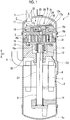
Fig. 1 is a longitudinal sectional view of a compressor according to a first embodiment of the present invention. -
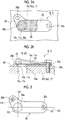
Fig. 2 shows a discharge valve mechanism according to the first embodiment of the present invention,Fig. 2A is a top view, andFig. 2B is a longitudinal sectional view. -
Fig. 3 is a top view of a seating plate of the discharge valve mechanism according to the first embodiment of the present invention. -
Fig. 4 is a longitudinal sectional view of a first modification example of the discharge valve mechanism according to the first embodiment of the present invention. -
Fig. 5 is a longitudinal sectional view of a second modification example of the discharge valve mechanism according to the first embodiment of the present invention. -
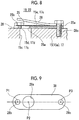
Fig. 6 is a longitudinal sectional view of a third modification example of the discharge valve mechanism according to the first embodiment of the present invention. -
Fig. 7 is a longitudinal sectional view of a fourth modification example of the discharge valve mechanism according to the first embodiment of the present invention. -
Fig. 8 is a longitudinal sectional view of a fifth modification example of the discharge valve mechanism according to the first embodiment of the present invention. -
Fig. 9 is a longitudinal sectional view of a sixth modification example of the discharge valve mechanism according to the first embodiment of the present invention. - Hereinafter, an embodiment to which the present invention is applied will be described in detail with reference to the drawings.
- In the embodiment, the following description will be made with a vertical scroll compressor, which is provided in an air conditioner, a chiller, and the like, given as an example of the compressor A.
- As shown in
Fig. 1 , the compressor A of the embodiment is configured by including ahousing 1, anelectric motor 2 provided inside thehousing 1, and ascroll compression mechanism 3, which is equally provided inside thehousing 1 and compresses a fluid, such as a refrigerant, by the driving of theelectric motor 2. - The
housing 1 includes a cylindrical housingmain body 1a, anupper cover 1b that closes an opening in an upper end of the housingmain body 1a, and alower cover 1c that closes an opening in a lower end of the housingmain body 1a. A suction pipe 4 for supplying a fluid, such as a refrigerant, into thehousing 1 from an accumulator (not shown) or the like is provided in thehousing 1, in particular, in a side surface of the housingmain body 1a. In addition, adischarge pipe 5 for discharging a fluid compressed by thescroll compression mechanism 3 to the outside is provided in theupper cover 1b. - The
electric motor 2 includes astator 6 and arotor 7, power is supplied from a power supply to thestator 6, and therotor 7 rotates about an axis O1 extending in a vertical direction S1. - A
rotary shaft 8 is integrally attached to therotor 7 such that an axis O1 direction matches the vertical direction S1. Therotary shaft 8 is provided such that an upper end and a lower end thereof in the axis O1 direction are pivotally supported by anupper bearing 10 and alower bearing 11 respectively and the rotary shaft rotates about the axis O1 along with the rotation of therotor 7. - Each of the
upper bearing 10 and thelower bearing 11 is provided to be integrally fixed to the housingmain body 1a. - An
eccentric pin 12 is integrally provided on an upper end portion of therotary shaft 8 such that an axis O2 thereof matches the vertical direction S1 and is eccentric (offset) with respect to the axis O1 of therotary shaft 8. - The
scroll compression mechanism 3 includes a fixed scroll 15 (base portion), an orbitingscroll 16 that is caused to revolve and orbit eccentrically with respect to the fixedscroll 15 by theelectric motor 2, and a discharge cover 17 (base portion). - The fixed
scroll 15 includes a disk-shapedend plate 15a and afixed wrap 15b that protrudes downwards from a lower surface of theend plate 15a and is provided in a spiral shape. The fixedscroll 15 is fixedly provided by being bonded to theupper bearing 10 with a bolt or the like and thereby being fixed inside thehousing 1. - The orbiting
scroll 16 is formed by including a disk-shapedend plate 16a and anorbiting wrap 16b that protrudes upwards from an upper surface of theend plate 16a and is fixedly provided in a spiral shape. Theorbiting wrap 16b of the orbitingscroll 16 is accommodated in the fixedwrap 15b of the fixedscroll 15. - In addition, a
boss 20 is integrally provided on a lower surface of theend plate 16a of the orbitingscroll 16, and theeccentric pin 12 is fitted to theboss 20. - Accordingly, the orbiting
scroll 16 is provided such that the orbiting scroll is eccentrically connected to therotary shaft 8, follows the rotation about the axis O1 of therotary shaft 8, and rotates (revolves) with an eccentric distance from the axis (shaft center) O1 of therotary shaft 8 as a radius. In addition, the orbitingscroll 16 revolves instead of spinning. - The fixed
scroll 15 and the orbitingscroll 16 cause the fixedwrap 15b and theorbiting wrap 16b to be meshed so as to vertically overlap each other. The fixedscroll 15 and the orbitingscroll 16 are eccentric with respect to each other by a predetermined amount, the fixedwrap 15b and theorbiting wrap 16b are meshed with each other with a 180 degree phase shift, and the fixedwrap 15b and theorbiting wrap 16b are in contact with each other at a plurality of places according to a rotation angle of the orbitingscroll 16. - Between a lower surface of the fixed
scroll 15 and an upper surface of the orbitingscroll 16, that is, a portion that allows the fixedwrap 15b and theorbiting wrap 16b to be meshed with each other is set as acompression chamber 21 that compresses a fluid, such as a refrigerant. Thescroll compression mechanism 3 of the embodiment is configured such that thecompression chamber 21 is formed to be point symmetric with respect to a center portion of a spiral of the fixedwrap 15b and theorbiting wrap 16b, and a fluid is compressed most at the center portion of the spiral by gradually transitioning to an inner peripheral side while decreasing a volume thereof according to orbiting motion of the orbitingscroll 16. - A
discharge port 15c, which penetrates theend plate 15a and communicates with a vertical space, is provided in theend plate 15a of the fixedscroll 15 at a position corresponding to a center portion of thecompression chamber 21, and a discharge valve mechanism C is configured on an upper surface side of thedischarge port 15c. The discharge valve mechanism C is a mechanism that opens and closes adischarge opening 15d of thedischarge port 15c according to a pressure difference between anintermediate chamber 19, which is between the fixedscroll 15 and thedischarge cover 17, and thecompression chamber 21. - The
discharge cover 17 is fixedly provided above the fixedscroll 15, and separates and divides the inside of thehousing 1 into a space on a lower portion side, to which is connected the suction pipe 4, and theintermediate chamber 19, and adischarge chamber 22 that is an upper portion side to which thedischarge pipe 5 is connected. - A
discharge port 17c, which penetrates thedischarge cover 17 and communicates with the vertical space, is provided in thedischarge cover 17, and a discharge valve mechanism B is configured on an upper surface side of thedischarge port 17c. The discharge valve mechanism B is a mechanism that opens and closes adischarge opening 17d of thedischarge port 17c according to a pressure difference between theintermediate chamber 19 and thedischarge chamber 22. - As shown in
Fig. 2A and 2B , each of the discharge valve mechanism B and the discharge valve mechanism C includes thedischarge port end plate 15a of the fixedscroll 15 or thedischarge cover 17, avalve seat end plate 15a of the fixedscroll 15 or an upper surface of thedischarge cover 17, avalve body 25 that opposes and closes thedischarge opening discharge port seating plate 28 that is disposed between theend plate 15a of the fixedscroll 15 or thedischarge cover 17 and thevalve body 25, and aretainer 26 that is disposed such that the retainer overlaps thevalve body 25 and thedischarge opening 17d from above. - The valve seats 15e and 17e are directly formed on an upper surface of the
end plate 15a of the fixedscroll 15 and the upper surface of thedischarge cover 17, respectively. Each of thevalve seats valve body 25 that the valve seat opposes, and is formed in a planar shape substantially over the entire region that opposes thevalve body 25 in the embodiment. Theend plate 15a, thevalve seat 15e, thedischarge cover 17, and thevalve seat 17e are made of, for example, cast iron. - The
valve body 25 is, for example, a reed valve made of stainless steel, oneend 25a thereof is fixed to theend plate 15a of the fixedscroll 15 or the upper surface of thedischarge cover 17. Theother end 25b thereof closes thedischarge port valve seat - The
valve body 25 is formed to be able to elastically deform with the oneend 25a fixed to theend plate 15a of the fixedscroll 15 or the upper surface of thedischarge cover 17 as fulcrum. - The
seating plate 28 is made of a material such as a metal harder than theend plate 15a of the fixedscroll 15 or the discharge cover 17 (for example, carbon tool steel (SK material) or the like). Both surfaces of theseating plate 28 are formed in a planar shape. One surface abuts against and supports a surface of thevalve body 25 on one side, and the other surface abuts against and is airtightly in close contact with thevalve seat - As shown in
Fig. 3 , theseating plate 28 has a through-hole 28a corresponding to thedischarge port portions end plate 15a of the fixedscroll 15 or thedischarge cover 17, which are provided at positions on both sides with respect to the center of the through-hole 28a. The fixingportions seating plate 28. - Specifically, a position of a center P1 of one fixing
portion 28b is disposed on an opposite side to a center P3 with astraight line 04 that passes through a center P2 of the through-hole 28a and is orthogonal to aline 03, which links the center P3 of the other fixingportion 28c and the center P2 of the through-hole 28a together, interposed therebetween. That is, the fixingportion 28b and the fixingportion 28c are disposed on both sides of an extension direction of theseating plate 28 with the center P2 of the through-hole 28a interposed therebetween. On theseating plate 28, the center P2 of the through-hole 28a and the center P3 of the fixingportion 28c are disposed on theline 03 in a straight line, and the position of the center P1 of the fixingportion 28b is not disposed on theline 03. Accordingly, theseating plate 28 has an L-shape in top view. - In the embodiment, one fixing
portion 28c is fixed to oneend 25a of thevalve body 25 and theend plate 15a of the fixedscroll 15 or thedischarge cover 17. - Although not particularly limited, as shown in
Fig. 4 , the through-hole 28a of theseating plate 28 may be formed to be larger than thedischarge opening discharge port hole 28a is formed to be a size larger than thedischarge opening hole 28a and thedischarge opening hole 28a surrounds thedischarge opening - In addition, as shown in
Fig. 5 , achamfer portion 28e may be provided in an edge portion of the through-hole 28a on avalve body 25 side in the embodiment. Thechamfer portion 28e is a surface inclined radially inner side of the through-hole 28a toward theend plate 15a or thedischarge cover 17. In an example ofFig. 5 , thechamfer portion 28e is formed from the edge portion of the through-hole 28a on thevalve body 25 side to a middle position in the extension direction of the through-hole 28a. Thechamfer portion 28e may be formed by machining the edge portion of the through-hole 28a, or press-sag formed when punching out the through-hole 28a may be set as thechamfer portion 28e at it is. - In addition, as shown in
Fig. 6 , aseal member 28d may be mounted between theseating plate 28 and theend plate 15a of the fixedscroll 15 or thedischarge cover 17 to annularly surround thedischarge port seal member 28d is a gasket, an O-ring, or the like. - The
retainer 26 is provided such that one end side thereof is fixed and supported by thedischarge cover 17 and is inclined upwards toward the other end side thereof so as to overlap thevalve body 25 and thedischarge opening 17d from above. Theretainer 26 restricts a lifted amount at each position when thevalve body 25 elastically deforms and is lifted up due to a pressure difference since the retainer is formed to be inclined from the one end side to the other end side. - In the embodiment, the
seating plate 28, thevalve body 25, and theretainer 26 are tightened together and fixed to theend plate 15a of the fixedscroll 15 or thedischarge cover 17 at the same position on one side. - When the
electric motor 2 causes theorbiting scroll 16 to revolve by orbiting at an eccentric position with respect to the fixedscroll 15 in such a compressor A, a refrigerant is compressed in thecompression chamber 21 between thefixed wrap 15b and theorbiting wrap 16b, both of which have a spiral shape, while the refrigerant is compressed most at the center portion of the spiral. - When a pressure of the
compression chamber 21 is equal to or lower than a pressure of theintermediate chamber 19 in the discharge valve mechanism B, theother end 25b side is maintained in a state of closing thedischarge opening 17d. Then, when the pressure of thecompression chamber 21 becomes higher than the pressure of theintermediate chamber 19, the fixed portion on the oneend 25a side is set as fulcrum, the valve body elastically deforms according to a pressure difference, and theother end 25b side is lifted up from thevalve seat 15e and theseating plate 28, thereby opening thedischarge opening 17d. Accordingly, a compressed fluid is fed from thecompression chamber 21 to theintermediate chamber 19 through thedischarge opening 17d. When the pressure of thecompression chamber 21 becomes equal to or lower than the pressure of theintermediate chamber 19, theother end 25b side of thevalve body 25 returns to an original state, thereby closing thedischarge opening 17d. - In addition, when the pressure of the
intermediate chamber 19 is equal to or lower than thedischarge chamber 22 in the discharge valve mechanism C, theother end 25b side is maintained in a state of closing thedischarge opening 17d. Then, when the pressure of theintermediate chamber 19 becomes higher than the pressure of thedischarge chamber 22, the fixed portion on the oneend 25a side is set as fulcrum, the valve body elastically deforms according to a pressure difference, and theother end 25b side is lifted up from thevalve seat 15e and theseating plate 28, thereby opening thedischarge opening 17d. Accordingly, a compressed fluid is fed from theintermediate chamber 19 to thedischarge chamber 22 through thedischarge opening 17d. When the pressure of thecompression chamber 21 becomes equal to or lower than the pressure of theintermediate chamber 19, theother end 25b side of thevalve body 25 returns to an original state, thereby closing thedischarge opening 17d. - By these processes being continued, the compressed fluid is in turn discharged from the
discharge pipe 5 and becomes available for use. - According to such a compressor A, the
seating plate 28, which is made of a material harder than theend plate 15a of the fixedscroll 15 or thedischarge cover 17, is disposed between theend plate 15a of the fixedscroll 15 or thedischarge cover 17 and thevalve body 25, and abuts against and supports one side surface of thevalve body 25. For this reason, thevalve body 25 does not directly abut against theend plate 15a of the fixedscroll 15 or thedischarge cover 17 at the time of opening and closing. Accordingly, it is possible to reliably prevent thevalve seat end plate 15a of the fixedscroll 15 or the discharge cover 17 from being damaged by a shock which occurs at the time of opening and closing of thevalve body 25. - In addition, the
seating plate 28, which is another member disposed between theend plate 15a of the fixedscroll 15 or thedischarge cover 17 and thevalve body 25, is fixed to theend plate 15a of the fixedscroll 15 or thedischarge cover 17 by the plurality of fixingportions seating plate 28 with the center P2 of the through-hole 28a corresponding to thedischarge port seating plate 28 can be easily mounted onto theend plate 15a of the fixedscroll 15 or thedischarge cover 17. It is possible to avoid that theseating plate 28 shifts a position thereof, floats, deforms, leaves a gap, or the like with respect to thevalve seat discharge port valve body 25, or the like. - Therefore, the compressing performance of the compressor A can be easily secured even under severe use conditions (operation conditions in a state where a rotation speed is high, or the like) while damage to the
valve seat - In addition, in the compressor A of the embodiment, since the
seating plate 28 is fixed at one fixingportion 28b to theend plate 15a of the fixedscroll 15 or thedischarge cover 17 along with the oneend 25a of thevalve body 25, a fixed position and fixing means of theseating plate 28 can be shared with the oneend 25a of thevalve body 25, and thus a structure can be simplified. - In addition, as shown in
Fig. 4 , the through-hole 28a of theseating plate 28 may be formed to be larger than thedischarge opening discharge port - In this case, it is possible to avoid that the
discharge opening discharge port seating plate 28 due to a manufacturing error of theseating plate 28, a position shift at the time of attaching theseating plate 28, backlash of theseating plate 28 at the time of operating the compressor A, or the like, and it is possible to suppress a pressure loss in thedischarge opening - In addition, as shown in
Fig. 5 , thechamfer portion 28e may be provided in theseating plate 28 in the compressor A of the embodiment. In this case, when thevalve body 25 is seated on theseating plate 28, it is possible to avoid that thevalve body 25 becomes damaged. Since an opening area of thedischarge opening - In addition, as shown in
Fig. 6 , theseal member 28d may be mounted between theseating plate 28 and theend plate 15a of the fixedscroll 15 or thedischarge cover 17 to annularly surround thedischarge port seating plate 28 and theend plate 15a of the fixedscroll 15 or thedischarge cover 17, and it is possible to easily secure the compressing performance of the compressor A. - Although an embodiment of the present invention has been described hereinbefore in detail with reference to the drawings, a specific configuration is not limited to the embodiment, and design modification that does not depart from the scope of the present invention is also included.
- For example, as shown in
Fig. 7 , a recessedportion seating plate 28 and has a depth that is the same as a thickness of theseating plate 28, may be formed in theend plate 15a or thedischarge cover 17. Theseating plate 28 is fitted in the recessedportion seating plate 28 with respect to theend plate 15a or thedischarge cover 17. - In addition, as shown in
Fig. 8 , the through-hole 28a of theseating plate 28 may be formed to be smaller than thedischarge opening discharge port hole 28a and thedischarge opening hole 28a is provided to be surrounded by thedischarge opening - In this case, since the through-
hole 28a of theseating plate 28 is formed to be smaller than thedischarge opening discharge port seating plate 28 on the discharge side of the discharge port. - For this reason, a sufficient opening area can be easily secured on the compression side, and a pressure loss, which occurs when a compressed fluid is introduced into the
discharge port seating plate 28. Since an area closed by thevalve body 25 can be made small in a state where a large opening area of thedischarge port valve body 25 gets into the through-hole 28a can be made unlikely when the through-hole 28a is closed by thevalve body 25, and thus sealability between thevalve body 25 and a vicinity of the through-hole 28a can be improved. In addition, the strength of theseating plate 28 and the strength of thevalve body 25 can be improved since the through-hole 28a of theseating plate 28 can be made small. - In addition, as shown in
Fig. 9 , each of the centers P1, P2, and P3 is arranged in a straight line shape on aseating plate 38, and theseating plate 38 may be in a straight line shape instead of being in an L-shape. That is, the shape of the seating plate is not particularly limited. It is sufficient that the fixing portions are provided on both sides of the extension direction of the seating plate with at least the center P2 of the through-hole 28a interposed therebetween. - In addition, although an example in which the shapes of various holes, including the
discharge port - In addition, it is not necessary to apply the configuration of the embodiment to both of the discharge valve mechanism B and the discharge valve mechanism C, and the configuration of the embodiment may be applied to at least one of the discharge valve mechanisms.
- In addition, although the compressor A has been described as a scroll compressor in the description above, each of the configurations described above may be applied to a rotary compressor or other compressors.
- The present invention is applicable to a compressor. Reference Signs List
-
- 1:
- housing
- 1a:
- housing main body
- 1b:
- upper cover
- 1c:
- lower cover
- 2:
- electric motor
- 3:
- scroll compression mechanism
- 4:
- suction pipe
- 5:
- discharge pipe
- 6:
- stator
- 7:
- rotor
- 8:
- rotary shaft
- 10:
- upper bearing
- 11:
- lower bearing
- 12:
- eccentric pin
- 15:
- fixed scroll (base portion)
- 15a:
- end plate
- 15b:
- fixed wrap
- 15c:
- discharge port
- 15d:
- discharge opening
- 15e:
- valve seat
- 15f:
- recessed portion
- 16:
- orbiting scroll
- 16a:
- end plate
- 16b:
- orbiting wrap
- 17:
- discharge cover (base portion)
- 17c:
- discharge port
- 17d:
- discharge opening
- 17e:
- valve seat
- 17f:
- recessed portion
- 19:
- intermediate chamber
- 20:
- boss
- 21:
- compression chamber
- 22:
- discharge chamber
- 25:
- valve body
- 25a:
- one end
- 25b:
- the other end
- 26:
- retainer
- 28:
- seating plate
- 28a:
- through-hole
- 28b:
- fixing portion
- 28c:
- fixing portion
- 28d:
- seal member
- 28e:
- chamfer portion
- 38:
- seating plate
- A:
- compressor
- B, C:
- discharge valve mechanism
- O1:
- axis
- O2:
- axis
- O3:
- line that links centers together
- O4:
- orthogonal line
- S1:
- vertical direction
- P1:
- center of one fixing portion
- P2:
- center of through-hole
- P3:
- center of the other fixing portion
Claims (6)
- A compressor comprising:a base portion that separates a compression side from a discharge side;a discharge port that penetrates the base portion;a valve body having one end, which is fixed to the base portion, and the other end, which opposes the base portion to close the discharge port, in which the other end elastically deforms to open the discharge port when a pressure of the compression side becomes higher than a pressure of the discharge side; anda seating plate that supports the valve body by being disposed between the base portion and the valve body and abutting against a surface of the valve body on a base portion side,wherein the seating plate is made of a material harder than the base portion, and has a through-hole corresponding to the discharge port and a plurality of fixing portions to the base portion, which are provided at positions on both sides of an extension direction with respect to a center of the through-hole.
- The compressor according to Claim 1,
wherein the seating plate is fixed to the base portion along with the one end of the valve body at at least one of the fixing portions. - The compressor according to Claim 1 or 2,
wherein the through-hole of the seating plate is formed to be larger than a discharge opening of the discharge port, and is provided to surround the discharge opening from an outer peripheral side. - The compressor according to Claim 1 or 2,
wherein the through-hole of the seating plate is formed to be smaller than a discharge opening of the discharge port, and is provided to be surrounded by the discharge opening from an outer peripheral side. - The compressor according to any one of Claims 1 to 4,
wherein a seal member is mounted between the seating plate and the base portion to annularly surround the discharge port. - The compressor according to any one of Claims 1 to 5,
wherein the through-hole has a chamfer portion in an edge portion on a valve body side.
Applications Claiming Priority (2)
| Application Number | Priority Date | Filing Date | Title |
|---|---|---|---|
| JP2017055712A JP7032864B2 (en) | 2017-03-22 | 2017-03-22 | Compressor |
| PCT/JP2018/000434 WO2018173428A1 (en) | 2017-03-22 | 2018-01-11 | Compressor |
Publications (3)
| Publication Number | Publication Date |
|---|---|
| EP3514385A1 true EP3514385A1 (en) | 2019-07-24 |
| EP3514385A4 EP3514385A4 (en) | 2019-11-13 |
| EP3514385B1 EP3514385B1 (en) | 2020-12-02 |
Family
ID=63585269
Family Applications (1)
| Application Number | Title | Priority Date | Filing Date |
|---|---|---|---|
| EP18770271.7A Active EP3514385B1 (en) | 2017-03-22 | 2018-01-11 | Compressor |
Country Status (6)
| Country | Link |
|---|---|
| EP (1) | EP3514385B1 (en) |
| JP (2) | JP7032864B2 (en) |
| KR (2) | KR20190049846A (en) |
| CN (1) | CN109844315B (en) |
| AU (1) | AU2018239557B2 (en) |
| WO (1) | WO2018173428A1 (en) |
Families Citing this family (3)
| Publication number | Priority date | Publication date | Assignee | Title |
|---|---|---|---|---|
| CN111005875A (en) * | 2019-12-02 | 2020-04-14 | 珠海格力节能环保制冷技术研究中心有限公司 | Exhaust assembly, pump body assembly and rotor type compressor |
| CN113847248B (en) * | 2021-10-22 | 2025-06-13 | 珠海格力节能环保制冷技术研究中心有限公司 | Exhaust valve components, compressors and air conditioners |
| CN113931845B (en) * | 2021-10-22 | 2025-07-18 | 珠海格力电器股份有限公司 | Vent valve assembly, compressor and air conditioner |
Family Cites Families (14)
| Publication number | Priority date | Publication date | Assignee | Title |
|---|---|---|---|---|
| JPS58172484A (en) * | 1982-04-02 | 1983-10-11 | Hitachi Koki Co Ltd | Oil check window of oil rotary vacuum pump |
| JPS58172482A (en) * | 1982-04-05 | 1983-10-11 | Hitachi Ltd | scroll compressor |
| JPS61215486A (en) * | 1985-03-20 | 1986-09-25 | Hitachi Ltd | Discharge port structure of rotary compressor |
| JPH01162089U (en) * | 1988-05-02 | 1989-11-10 | ||
| JPH0466391U (en) * | 1990-10-15 | 1992-06-11 | ||
| JPH08319963A (en) * | 1995-03-22 | 1996-12-03 | Mitsubishi Electric Corp | Scroll compressor |
| JPH08338368A (en) * | 1995-06-09 | 1996-12-24 | Tokico Ltd | Compressor |
| KR100202897B1 (en) | 1996-11-22 | 1999-06-15 | 전주범 | Flapper type discharge valve caulking structure of compressor |
| JP2001099066A (en) * | 1999-09-28 | 2001-04-10 | Sanyo Electric Co Ltd | Refrigerant compressor |
| KR100652588B1 (en) * | 2004-11-11 | 2006-12-07 | 엘지전자 주식회사 | Discharge Valve System of Scroll Compressor |
| JP5652613B2 (en) * | 2011-03-08 | 2015-01-14 | サンデン株式会社 | Compressor valve equipment |
| JP5429353B1 (en) * | 2012-07-25 | 2014-02-26 | ダイキン工業株式会社 | Compressor |
| JP2016014326A (en) * | 2014-07-01 | 2016-01-28 | カルソニックカンセイ株式会社 | Compressor |
| WO2016139796A1 (en) * | 2015-03-05 | 2016-09-09 | 三菱電機株式会社 | Compressor |
-
2017
- 2017-03-22 JP JP2017055712A patent/JP7032864B2/en active Active
-
2018
- 2018-01-11 KR KR1020197010576A patent/KR20190049846A/en not_active Ceased
- 2018-01-11 WO PCT/JP2018/000434 patent/WO2018173428A1/en not_active Ceased
- 2018-01-11 CN CN201880003905.0A patent/CN109844315B/en active Active
- 2018-01-11 AU AU2018239557A patent/AU2018239557B2/en active Active
- 2018-01-11 EP EP18770271.7A patent/EP3514385B1/en active Active
- 2018-01-11 KR KR1020217008201A patent/KR102327970B1/en active Active
-
2022
- 2022-01-12 JP JP2022003170A patent/JP7595605B2/en active Active
Also Published As
| Publication number | Publication date |
|---|---|
| CN109844315B (en) | 2020-12-08 |
| JP2022040255A (en) | 2022-03-10 |
| KR20190049846A (en) | 2019-05-09 |
| JP7595605B2 (en) | 2024-12-06 |
| AU2018239557A1 (en) | 2019-04-18 |
| WO2018173428A1 (en) | 2018-09-27 |
| KR20210034105A (en) | 2021-03-29 |
| CN109844315A (en) | 2019-06-04 |
| AU2018239557B2 (en) | 2020-07-23 |
| EP3514385A4 (en) | 2019-11-13 |
| EP3514385B1 (en) | 2020-12-02 |
| KR102327970B1 (en) | 2021-11-17 |
| JP7032864B2 (en) | 2022-03-09 |
| JP2018159287A (en) | 2018-10-11 |
Similar Documents
| Publication | Publication Date | Title |
|---|---|---|
| JP7595605B2 (en) | Compressor | |
| JP6395059B2 (en) | Scroll compressor | |
| EP2500517B1 (en) | Scroll-type compressor for vehicle | |
| US9366253B2 (en) | Scroll compressor and processing method of scroll including a projection on a tip seal and a hole in a tip seal groove | |
| EP3054159B1 (en) | Compressor | |
| EP3951181B1 (en) | Rotary compressor | |
| JPWO2017158665A1 (en) | Scroll compressor | |
| JP2006177223A (en) | Rotary type two-stage compressor | |
| EP2549109A2 (en) | Scroll compressor | |
| CN111133196A (en) | Cross slip ring and scroll compressor | |
| EP3376032B1 (en) | Compressor | |
| JP5033391B2 (en) | Rotary compressor | |
| EP0471425A1 (en) | Scroll type fluid machinery | |
| US20240052838A1 (en) | A compressor | |
| JP6582244B2 (en) | Scroll compressor | |
| JP4875411B2 (en) | Scroll compressor | |
| EP3936724A1 (en) | Scroll compressor | |
| JP2003155987A (en) | Defrosting device for refrigerant circuit and rotary compressor for refrigerant circuit | |
| JP2006063943A (en) | Scroll compressor | |
| JP2017089448A (en) | Scroll fluid machine |
Legal Events
| Date | Code | Title | Description |
|---|---|---|---|
| STAA | Information on the status of an ep patent application or granted ep patent |
Free format text: STATUS: THE INTERNATIONAL PUBLICATION HAS BEEN MADE |
|
| PUAI | Public reference made under article 153(3) epc to a published international application that has entered the european phase |
Free format text: ORIGINAL CODE: 0009012 |
|
| STAA | Information on the status of an ep patent application or granted ep patent |
Free format text: STATUS: REQUEST FOR EXAMINATION WAS MADE |
|
| 17P | Request for examination filed |
Effective date: 20190417 |
|
| AK | Designated contracting states |
Kind code of ref document: A1 Designated state(s): AL AT BE BG CH CY CZ DE DK EE ES FI FR GB GR HR HU IE IS IT LI LT LU LV MC MK MT NL NO PL PT RO RS SE SI SK SM TR |
|
| AX | Request for extension of the european patent |
Extension state: BA ME |
|
| A4 | Supplementary search report drawn up and despatched |
Effective date: 20191011 |
|
| RIC1 | Information provided on ipc code assigned before grant |
Ipc: F04B 39/14 20060101ALI20191007BHEP Ipc: F04C 29/12 20060101ALI20191007BHEP Ipc: F04B 53/10 20060101ALN20191007BHEP Ipc: F04B 39/10 20060101AFI20191007BHEP Ipc: F04C 23/00 20060101ALN20191007BHEP Ipc: F04C 18/02 20060101ALN20191007BHEP |
|
| DAV | Request for validation of the european patent (deleted) | ||
| DAX | Request for extension of the european patent (deleted) | ||
| GRAP | Despatch of communication of intention to grant a patent |
Free format text: ORIGINAL CODE: EPIDOSNIGR1 |
|
| STAA | Information on the status of an ep patent application or granted ep patent |
Free format text: STATUS: GRANT OF PATENT IS INTENDED |
|
| RIC1 | Information provided on ipc code assigned before grant |
Ipc: F04C 23/00 20060101ALN20200623BHEP Ipc: F04C 18/02 20060101ALN20200623BHEP Ipc: F04B 39/14 20060101ALI20200623BHEP Ipc: F04C 29/12 20060101ALI20200623BHEP Ipc: F04B 53/10 20060101ALN20200623BHEP Ipc: F04B 39/10 20060101AFI20200623BHEP |
|
| INTG | Intention to grant announced |
Effective date: 20200714 |
|
| GRAS | Grant fee paid |
Free format text: ORIGINAL CODE: EPIDOSNIGR3 |
|
| GRAA | (expected) grant |
Free format text: ORIGINAL CODE: 0009210 |
|
| STAA | Information on the status of an ep patent application or granted ep patent |
Free format text: STATUS: THE PATENT HAS BEEN GRANTED |
|
| AK | Designated contracting states |
Kind code of ref document: B1 Designated state(s): AL AT BE BG CH CY CZ DE DK EE ES FI FR GB GR HR HU IE IS IT LI LT LU LV MC MK MT NL NO PL PT RO RS SE SI SK SM TR |
|
| REG | Reference to a national code |
Ref country code: GB Ref legal event code: FG4D |
|
| REG | Reference to a national code |
Ref country code: AT Ref legal event code: REF Ref document number: 1341217 Country of ref document: AT Kind code of ref document: T Effective date: 20201215 Ref country code: CH Ref legal event code: EP |
|
| REG | Reference to a national code |
Ref country code: IE Ref legal event code: FG4D |
|
| REG | Reference to a national code |
Ref country code: DE Ref legal event code: R096 Ref document number: 602018010470 Country of ref document: DE |
|
| PG25 | Lapsed in a contracting state [announced via postgrant information from national office to epo] |
Ref country code: FI Free format text: LAPSE BECAUSE OF FAILURE TO SUBMIT A TRANSLATION OF THE DESCRIPTION OR TO PAY THE FEE WITHIN THE PRESCRIBED TIME-LIMIT Effective date: 20201202 Ref country code: RS Free format text: LAPSE BECAUSE OF FAILURE TO SUBMIT A TRANSLATION OF THE DESCRIPTION OR TO PAY THE FEE WITHIN THE PRESCRIBED TIME-LIMIT Effective date: 20201202 Ref country code: NO Free format text: LAPSE BECAUSE OF FAILURE TO SUBMIT A TRANSLATION OF THE DESCRIPTION OR TO PAY THE FEE WITHIN THE PRESCRIBED TIME-LIMIT Effective date: 20210302 Ref country code: GR Free format text: LAPSE BECAUSE OF FAILURE TO SUBMIT A TRANSLATION OF THE DESCRIPTION OR TO PAY THE FEE WITHIN THE PRESCRIBED TIME-LIMIT Effective date: 20210303 |
|
| REG | Reference to a national code |
Ref country code: NL Ref legal event code: MP Effective date: 20201202 |
|
| REG | Reference to a national code |
Ref country code: AT Ref legal event code: MK05 Ref document number: 1341217 Country of ref document: AT Kind code of ref document: T Effective date: 20201202 |
|
| PG25 | Lapsed in a contracting state [announced via postgrant information from national office to epo] |
Ref country code: BG Free format text: LAPSE BECAUSE OF FAILURE TO SUBMIT A TRANSLATION OF THE DESCRIPTION OR TO PAY THE FEE WITHIN THE PRESCRIBED TIME-LIMIT Effective date: 20210302 Ref country code: LV Free format text: LAPSE BECAUSE OF FAILURE TO SUBMIT A TRANSLATION OF THE DESCRIPTION OR TO PAY THE FEE WITHIN THE PRESCRIBED TIME-LIMIT Effective date: 20201202 Ref country code: PL Free format text: LAPSE BECAUSE OF FAILURE TO SUBMIT A TRANSLATION OF THE DESCRIPTION OR TO PAY THE FEE WITHIN THE PRESCRIBED TIME-LIMIT Effective date: 20201202 Ref country code: SE Free format text: LAPSE BECAUSE OF FAILURE TO SUBMIT A TRANSLATION OF THE DESCRIPTION OR TO PAY THE FEE WITHIN THE PRESCRIBED TIME-LIMIT Effective date: 20201202 |
|
| PG25 | Lapsed in a contracting state [announced via postgrant information from national office to epo] |
Ref country code: NL Free format text: LAPSE BECAUSE OF FAILURE TO SUBMIT A TRANSLATION OF THE DESCRIPTION OR TO PAY THE FEE WITHIN THE PRESCRIBED TIME-LIMIT Effective date: 20201202 Ref country code: HR Free format text: LAPSE BECAUSE OF FAILURE TO SUBMIT A TRANSLATION OF THE DESCRIPTION OR TO PAY THE FEE WITHIN THE PRESCRIBED TIME-LIMIT Effective date: 20201202 |
|
| REG | Reference to a national code |
Ref country code: LT Ref legal event code: MG9D |
|
| PG25 | Lapsed in a contracting state [announced via postgrant information from national office to epo] |
Ref country code: SK Free format text: LAPSE BECAUSE OF FAILURE TO SUBMIT A TRANSLATION OF THE DESCRIPTION OR TO PAY THE FEE WITHIN THE PRESCRIBED TIME-LIMIT Effective date: 20201202 Ref country code: SM Free format text: LAPSE BECAUSE OF FAILURE TO SUBMIT A TRANSLATION OF THE DESCRIPTION OR TO PAY THE FEE WITHIN THE PRESCRIBED TIME-LIMIT Effective date: 20201202 Ref country code: CZ Free format text: LAPSE BECAUSE OF FAILURE TO SUBMIT A TRANSLATION OF THE DESCRIPTION OR TO PAY THE FEE WITHIN THE PRESCRIBED TIME-LIMIT Effective date: 20201202 Ref country code: EE Free format text: LAPSE BECAUSE OF FAILURE TO SUBMIT A TRANSLATION OF THE DESCRIPTION OR TO PAY THE FEE WITHIN THE PRESCRIBED TIME-LIMIT Effective date: 20201202 Ref country code: LT Free format text: LAPSE BECAUSE OF FAILURE TO SUBMIT A TRANSLATION OF THE DESCRIPTION OR TO PAY THE FEE WITHIN THE PRESCRIBED TIME-LIMIT Effective date: 20201202 Ref country code: PT Free format text: LAPSE BECAUSE OF FAILURE TO SUBMIT A TRANSLATION OF THE DESCRIPTION OR TO PAY THE FEE WITHIN THE PRESCRIBED TIME-LIMIT Effective date: 20210405 Ref country code: RO Free format text: LAPSE BECAUSE OF FAILURE TO SUBMIT A TRANSLATION OF THE DESCRIPTION OR TO PAY THE FEE WITHIN THE PRESCRIBED TIME-LIMIT Effective date: 20201202 |
|
| PG25 | Lapsed in a contracting state [announced via postgrant information from national office to epo] |
Ref country code: AT Free format text: LAPSE BECAUSE OF FAILURE TO SUBMIT A TRANSLATION OF THE DESCRIPTION OR TO PAY THE FEE WITHIN THE PRESCRIBED TIME-LIMIT Effective date: 20201202 |
|
| REG | Reference to a national code |
Ref country code: CH Ref legal event code: PL |
|
| REG | Reference to a national code |
Ref country code: DE Ref legal event code: R097 Ref document number: 602018010470 Country of ref document: DE |
|
| PG25 | Lapsed in a contracting state [announced via postgrant information from national office to epo] |
Ref country code: IS Free format text: LAPSE BECAUSE OF FAILURE TO SUBMIT A TRANSLATION OF THE DESCRIPTION OR TO PAY THE FEE WITHIN THE PRESCRIBED TIME-LIMIT Effective date: 20210402 Ref country code: MC Free format text: LAPSE BECAUSE OF FAILURE TO SUBMIT A TRANSLATION OF THE DESCRIPTION OR TO PAY THE FEE WITHIN THE PRESCRIBED TIME-LIMIT Effective date: 20201202 Ref country code: LU Free format text: LAPSE BECAUSE OF NON-PAYMENT OF DUE FEES Effective date: 20210111 |
|
| REG | Reference to a national code |
Ref country code: BE Ref legal event code: MM Effective date: 20210131 |
|
| PLBE | No opposition filed within time limit |
Free format text: ORIGINAL CODE: 0009261 |
|
| STAA | Information on the status of an ep patent application or granted ep patent |
Free format text: STATUS: NO OPPOSITION FILED WITHIN TIME LIMIT |
|
| PG25 | Lapsed in a contracting state [announced via postgrant information from national office to epo] |
Ref country code: AL Free format text: LAPSE BECAUSE OF FAILURE TO SUBMIT A TRANSLATION OF THE DESCRIPTION OR TO PAY THE FEE WITHIN THE PRESCRIBED TIME-LIMIT Effective date: 20201202 Ref country code: IT Free format text: LAPSE BECAUSE OF FAILURE TO SUBMIT A TRANSLATION OF THE DESCRIPTION OR TO PAY THE FEE WITHIN THE PRESCRIBED TIME-LIMIT Effective date: 20201202 |
|
| 26N | No opposition filed |
Effective date: 20210903 |
|
| PG25 | Lapsed in a contracting state [announced via postgrant information from national office to epo] |
Ref country code: LI Free format text: LAPSE BECAUSE OF NON-PAYMENT OF DUE FEES Effective date: 20210131 Ref country code: CH Free format text: LAPSE BECAUSE OF NON-PAYMENT OF DUE FEES Effective date: 20210131 Ref country code: DK Free format text: LAPSE BECAUSE OF FAILURE TO SUBMIT A TRANSLATION OF THE DESCRIPTION OR TO PAY THE FEE WITHIN THE PRESCRIBED TIME-LIMIT Effective date: 20201202 Ref country code: SI Free format text: LAPSE BECAUSE OF FAILURE TO SUBMIT A TRANSLATION OF THE DESCRIPTION OR TO PAY THE FEE WITHIN THE PRESCRIBED TIME-LIMIT Effective date: 20201202 |
|
| PG25 | Lapsed in a contracting state [announced via postgrant information from national office to epo] |
Ref country code: IE Free format text: LAPSE BECAUSE OF NON-PAYMENT OF DUE FEES Effective date: 20210111 Ref country code: ES Free format text: LAPSE BECAUSE OF FAILURE TO SUBMIT A TRANSLATION OF THE DESCRIPTION OR TO PAY THE FEE WITHIN THE PRESCRIBED TIME-LIMIT Effective date: 20201202 |
|
| PG25 | Lapsed in a contracting state [announced via postgrant information from national office to epo] |
Ref country code: IS Free format text: LAPSE BECAUSE OF FAILURE TO SUBMIT A TRANSLATION OF THE DESCRIPTION OR TO PAY THE FEE WITHIN THE PRESCRIBED TIME-LIMIT Effective date: 20210402 |
|
| PG25 | Lapsed in a contracting state [announced via postgrant information from national office to epo] |
Ref country code: BE Free format text: LAPSE BECAUSE OF NON-PAYMENT OF DUE FEES Effective date: 20210131 |
|
| PG25 | Lapsed in a contracting state [announced via postgrant information from national office to epo] |
Ref country code: CY Free format text: LAPSE BECAUSE OF FAILURE TO SUBMIT A TRANSLATION OF THE DESCRIPTION OR TO PAY THE FEE WITHIN THE PRESCRIBED TIME-LIMIT Effective date: 20201202 |
|
| PG25 | Lapsed in a contracting state [announced via postgrant information from national office to epo] |
Ref country code: HU Free format text: LAPSE BECAUSE OF FAILURE TO SUBMIT A TRANSLATION OF THE DESCRIPTION OR TO PAY THE FEE WITHIN THE PRESCRIBED TIME-LIMIT; INVALID AB INITIO Effective date: 20180111 |
|
| PG25 | Lapsed in a contracting state [announced via postgrant information from national office to epo] |
Ref country code: MK Free format text: LAPSE BECAUSE OF FAILURE TO SUBMIT A TRANSLATION OF THE DESCRIPTION OR TO PAY THE FEE WITHIN THE PRESCRIBED TIME-LIMIT Effective date: 20201202 |
|
| PG25 | Lapsed in a contracting state [announced via postgrant information from national office to epo] |
Ref country code: TR Free format text: LAPSE BECAUSE OF FAILURE TO SUBMIT A TRANSLATION OF THE DESCRIPTION OR TO PAY THE FEE WITHIN THE PRESCRIBED TIME-LIMIT Effective date: 20201202 |
|
| PG25 | Lapsed in a contracting state [announced via postgrant information from national office to epo] |
Ref country code: MT Free format text: LAPSE BECAUSE OF FAILURE TO SUBMIT A TRANSLATION OF THE DESCRIPTION OR TO PAY THE FEE WITHIN THE PRESCRIBED TIME-LIMIT Effective date: 20201202 |
|
| PGFP | Annual fee paid to national office [announced via postgrant information from national office to epo] |
Ref country code: GB Payment date: 20251127 Year of fee payment: 9 |
|
| PGFP | Annual fee paid to national office [announced via postgrant information from national office to epo] |
Ref country code: FR Payment date: 20251128 Year of fee payment: 9 |
|
| PGFP | Annual fee paid to national office [announced via postgrant information from national office to epo] |
Ref country code: DE Payment date: 20251203 Year of fee payment: 9 |