EP3513675B1 - Orthopädische schaumkunststoff-schuheinlage - Google Patents
Orthopädische schaumkunststoff-schuheinlage Download PDFInfo
- Publication number
- EP3513675B1 EP3513675B1 EP18152947.0A EP18152947A EP3513675B1 EP 3513675 B1 EP3513675 B1 EP 3513675B1 EP 18152947 A EP18152947 A EP 18152947A EP 3513675 B1 EP3513675 B1 EP 3513675B1
- Authority
- EP
- European Patent Office
- Prior art keywords
- layer
- foam plastic
- core part
- foam
- shoe
- Prior art date
- Legal status (The legal status is an assumption and is not a legal conclusion. Google has not performed a legal analysis and makes no representation as to the accuracy of the status listed.)
- Active
Links
Images


Classifications
-
- A—HUMAN NECESSITIES
- A43—FOOTWEAR
- A43B—CHARACTERISTIC FEATURES OF FOOTWEAR; PARTS OF FOOTWEAR
- A43B17/00—Insoles for insertion, e.g. footbeds or inlays, for attachment to the shoe after the upper has been joined
- A43B17/003—Insoles for insertion, e.g. footbeds or inlays, for attachment to the shoe after the upper has been joined characterised by the material
- A43B17/006—Insoles for insertion, e.g. footbeds or inlays, for attachment to the shoe after the upper has been joined characterised by the material multilayered
-
- A—HUMAN NECESSITIES
- A43—FOOTWEAR
- A43B—CHARACTERISTIC FEATURES OF FOOTWEAR; PARTS OF FOOTWEAR
- A43B17/00—Insoles for insertion, e.g. footbeds or inlays, for attachment to the shoe after the upper has been joined
- A43B17/14—Insoles for insertion, e.g. footbeds or inlays, for attachment to the shoe after the upper has been joined made of sponge, rubber, or plastic materials
-
- A—HUMAN NECESSITIES
- A43—FOOTWEAR
- A43B—CHARACTERISTIC FEATURES OF FOOTWEAR; PARTS OF FOOTWEAR
- A43B7/00—Footwear with health or hygienic arrangements
- A43B7/14—Footwear with health or hygienic arrangements with foot-supporting parts
- A43B7/1405—Footwear with health or hygienic arrangements with foot-supporting parts with pads or holes on one or more locations, or having an anatomical or curved form
- A43B7/141—Footwear with health or hygienic arrangements with foot-supporting parts with pads or holes on one or more locations, or having an anatomical or curved form having an anatomical or curved form
-
- A—HUMAN NECESSITIES
- A61—MEDICAL OR VETERINARY SCIENCE; HYGIENE
- A61F—FILTERS IMPLANTABLE INTO BLOOD VESSELS; PROSTHESES; DEVICES PROVIDING PATENCY TO, OR PREVENTING COLLAPSING OF, TUBULAR STRUCTURES OF THE BODY, e.g. STENTS; ORTHOPAEDIC, NURSING OR CONTRACEPTIVE DEVICES; FOMENTATION; TREATMENT OR PROTECTION OF EYES OR EARS; BANDAGES, DRESSINGS OR ABSORBENT PADS; FIRST-AID KITS
- A61F5/00—Orthopaedic methods or devices for non-surgical treatment of bones or joints; Nursing devices ; Anti-rape devices
- A61F5/01—Orthopaedic devices, e.g. long-term immobilising or pressure directing devices for treating broken or deformed bones such as splints, casts or braces
- A61F5/14—Special medical insertions for shoes for flat-feet, club-feet or the like
-
- B—PERFORMING OPERATIONS; TRANSPORTING
- B29—WORKING OF PLASTICS; WORKING OF SUBSTANCES IN A PLASTIC STATE IN GENERAL
- B29D—PRODUCING PARTICULAR ARTICLES FROM PLASTICS OR FROM SUBSTANCES IN A PLASTIC STATE
- B29D35/00—Producing footwear
- B29D35/12—Producing parts thereof, e.g. soles, heels, uppers, by a moulding technique
- B29D35/14—Multilayered parts
-
- B—PERFORMING OPERATIONS; TRANSPORTING
- B29—WORKING OF PLASTICS; WORKING OF SUBSTANCES IN A PLASTIC STATE IN GENERAL
- B29D—PRODUCING PARTICULAR ARTICLES FROM PLASTICS OR FROM SUBSTANCES IN A PLASTIC STATE
- B29D35/00—Producing footwear
- B29D35/12—Producing parts thereof, e.g. soles, heels, uppers, by a moulding technique
- B29D35/14—Multilayered parts
- B29D35/142—Soles
Definitions
- the invention relates to orthopedic foam plastic shoe inserts, in particular orthopedic foam plastic shoe inserts, which are produced using the RIM foaming process.
- the present invention further relates in particular to foam plastic shoe inserts with an orthopedic footbed on the upper side of the shoe insert that is produced using the RIM foaming process.
- the shoe insert according to the invention or the method according to the invention for producing such a shoe insert furthermore has a lower cover and, if appropriate, an upper cover to improve the wearing comfort.
- the shoe insert according to the invention has a core part which stabilizes the shoe insert and is produced by the injection molding process.
- EP 1 967 086 A1 plan to design the outside of the core part so that the PU foam foamed there is only so easily attached to the fact that it is easily removable by hand.
- an outside of the core part can be exposed in a simple manner and thus made editable.
- the outer side of the core stabilizing core part is placed directly on the shaping inner side of the PU foam mold. So that the core part according to this state of the art does not float during the RIM foaming process in the RIM foam mold, the core part is pre-shaped in its transverse dimensions transversely to the cavity of the foam mold, that is to say transversely to the closing direction, so that it has a press fit in the mold half the RIM foam shape is held.
- the core part is preferably preformed in a first PU foaming step.
- the core part is foamed with PU foam plastic and the finished shoe insert is foamed using the RIM process.
- the core part is foamed with PU foam plastic and the finished shoe insert is foamed using the RIM process.
- this leads to a relatively thick foam plastic shoe insert which, before it can be inserted into a shoe, often requires the inner sole of the shoe to be removed so that, in particular, the heel holder of the shoe is not lost or does not change or adversely affect other shoe biometric properties will.
- EP 1 602 294 A1 can be covered in a conventional manner on the respective top and / or bottom by means of an adhesive step with a corresponding top or bottom cover. Furthermore, the documents reveal EP 2 918 185 A1 , EP 1 516 715 A1 and EP 2 910 677 A1 also orthopedic insoles with a core part and method for producing orthopedic shoe insoles.
- the object of the invention is therefore to provide a simplified manufacturing process for such a foam plastic shoe insert which can be produced in the RIM process and which has a sole-stabilizing core part, on the one hand simplifying the manufacturing process on the one hand and on the other hand the additional effort and effort required for covering / gluing a PU Foam plastic blanks with a false ceiling and possibly with an upper ceiling is reduced to a minimum.
- the number of necessary process steps, the specific receptacles, the special tools and special forms for forming the foam plastic shoe insert are to be reduced as far as possible.
- a shoe orthopedic technician should also be able to adapt the core part of the PU shoe insert according to the invention to the needs of the wearer of the shoe insert to be able to.
- the manufacturing method according to the invention it should be possible to manufacture foam plastic shoe inserts with reduced wall thickness, which can be inserted into a shoe as far as possible without any significant change in the biometric conditions, without changes to the shoe, such as the removal of the shoe insole, being necessary.
- the method according to the invention for producing a PU foam plastic shoe insert should be as simple as possible in its design, inexpensive and robust, in order to be able to produce high-quality, orthopedically effective foam plastic shoe inserts inexpensively.
- an orthopedically effective core part can first be produced by the injection molding process, which means that the wall thickness in the thickness direction of the later shoe insert is thin or even very depending on the injection molding material used can be designed thin.
- the core parts / inserts made from PU foam plastic in the prior art had to be designed for the finished PU shoe insert with relatively large wall thicknesses in addition to the orthopedic function, in particular also for their press fit (see above) in the foam mold. This is on the one hand so that the core part has a stabilizing and thus also orthopedic effect on the shoe insert and on the other hand so that the foamed core part can generate sufficiently high elastic forces to hold the core part with a press fit in the foam mold.
- the orthopedically important functions of the sole-stabilizing and foot-supporting core part can be achieved with very small wall thicknesses by injection molding the core part.
- the core part according to the invention By positioning and fixing the core part according to the invention at a first layer, the core part together with the first layer can be inserted into the RIM foam mold in the orthopedically predetermined position and fixed there. It is no longer necessary to fix the core part with pins or with a press fit.
- an overall thinner foam plastic shoe insert can be produced that nevertheless meets all orthopedic requirements, in particular with regard to support and cushioning effect.
- the first layer preferably forms the false ceiling at the same time.
- the first layer is provided, for example, with a layer impermeable to PU foam plastic or consists of a material impermeable to foam plastic. At least the side of the first layer that comes into contact with the PU foam plastic adheres to the PU foam plastic or even forms a connection with it. The other side then forms at least partially the underside of the later shoe insert.
- the first layer is formed from a flexible material which is permeable to the foam plastic, according to the invention, before inserting the first layer with the core part molded onto it, into the first foam mold half of a foam molding tool, a second flexible material layer is formed between the shaping surface of the foam mold and the first layer inserted, which then forms the false ceiling, the foam plastic preferably not being able to penetrate the second layer of material.
- the side of the second layer facing the shaping surface then also forms here at least partially the underside of the later shoe insert.
- the relevant specialist recognizes that it is irrelevant in the sense of the invention on which side of the first flexible layer the core part is molded.
- the inventive concept encompasses both an inner orthopedic core part with respect to the shoe insert and an outer orthopedically active core part. If an inner core part is specifically desired, this could previously only be achieved in the prior art by completely foaming it or by subsequently gluing it to a false ceiling. According to the invention, this is now achieved in a simplified manner in that the core part is in the RIM foam shape is inserted and fixed on the side of the first flexible layer facing away from the shaping surface. After foaming the cushion body, the first flexible layer covers the core part, so that it is only vaguely visible, but can be felt.
- the core part is molded on a foam-plastic-permeable first flexible layer, its orientation can be chosen freely, since in this case a second flexible layer, which forms the lower cover of the later shoe insert, between the shaping surface of the first foam mold half and the first flexible layer is inserted and fixed with the molded core part.
- the step of subsequently covering the shoe insert for example by gluing, requiring much care and cleanliness can be omitted, at least for the underside.
- the molding of the core part onto a flexible material layer the dimensions of which are greater in the mold parting plane than the corresponding dimension of the shaping surface of the first RIM foam mold half, not only facilitates the handling of the core part, but in particular its fixing in an orthopedically predetermined position.
- the fixation of the core part according to the prior art by means of pins which penetrate into the core part or by means of a press fit is more complex and often less precise in this regard, especially when inserting by means of a press fit or when inserting small core parts by means of pins.
- the invention achieves a more precise positioning with the shaping by means of injection molding of the core part onto a flexible position, which is later hooked into the RIM foam mold, since the distances between the mounting points are further apart than, for example, with the holding pins in the prior art, and so on Deviations at the pick-up points have less influence on the orthopedically predetermined position of the core part in the shoe insert.
- a better seal between the two foam mold halves can be achieved via the flexible material of the first layer and / or second layer, as a result of which reworking, in particular the removal of foam lugs, is largely eliminated.
- the orthopedically active core parts produced according to the invention in the injection molding process, for example through the use of a PP, PE, PS or a TPE material, a much smaller wall thickness of the core part can also be achieved than is possible with core parts made of foamed PU .
- This reduction in wall thickness according to the invention is particularly evident when using the shoe insert according to the invention in Sports shoes, casual shoes, street shoes, work shoes or similar footwear is advantageous as an orthopedic shoe insert, since the wearing properties of the shoe are only minimally influenced.
- fiber-reinforced plastics such as CFRP or GFRP plastics, ie plastics reinforced with carbon fiber or glass fiber, are used in the production of the core part, a further reduction in the wall thickness of the core part can be achieved.
- thermoplastic and thermoelastic materials can be used, which also includes the use of TPU (thermoplastic polyurethane).
- TPU thermoplastic polyurethane
- the invention also includes thermosetting materials as injection molding materials, even if their use in shoe inserts is rare due to their brittleness and formation of sharp edges in the event of breakage.
- the lower the wall thickness of the core part can be, the thinner the cushion layer / body, among other things. can also be designed to upholster the edges which interfere with comfort. Both soft and hard PU foams can be used for cushioning, which provide the desired or orthopedically required cushioning or stability of the shoe insert.
- the core part can thus extend from the heel area up to and including the toe area or only over partial areas, such as the midfoot area, in order to support the longitudinal arch area in particular.
- a design of the core part which for example comprises the longitudinal arch area of the shoe insert and the heel area, can be cleared in partial areas, such as below the heel spur, so that in the subsequent PU foaming process this clearance can be filled with damping PU foam, which is particularly the case with Diabetic soles is preferred.
- the molding / molding of the sole-stabilizing and foot-supporting core part according to the invention onto a first flexible layer can in particular also take place individually, since the position of the core part can be exactly maintained in the subsequent foaming process by the firm connection to the first flexible layer. It is therefore conceivable that the core part is adapted to the individual needs of a wearer of the shoe insert before the step of RIM foaming. Due to the exact transferability of the position of the core part by means of the first layer on which it is molded / molded, it is also possible to achieve a high and precise Achieve repeatability in the positioning of the core part in the PU foam plastic shoe inserts according to the invention.
- the manufacturing method according to the invention can be used to produce a large variety of PU shoe insoles with a sole-stabilizing core part, which allow the most varied combinations of materials and / or colors and / or shapes of false ceilings.
- An analogous situation applies to top ceilings if such is also foamed onto the top in the RIM foaming step according to the invention. More details on this later.
- the sole hardness specifications of orthopedic technicians for the core part as well as for the PU foam plastic as well as for the lower and upper covers can be individually and flexibly considered and implemented in a simple manner.
- the core part in the later shoe insert can be arranged both on the inside of the shoe insert and on the outside of the shoe insert (see above ). If the core part is arranged on the outside of the later shoe insert, it will later be easily accessible for a shoe orthopedic technician for individual adaptation to the foot of the wearer of the shoe insert.
- the core part material especially when the core part is arranged on the outside of the finished shoe insert, materials can also be used that do not form a firm connection with the PU foam plastic.
- This freedom of design can also be used for internal core parts, however, the core part should then preferably be surrounded on the free sides by PU foam plastic so that the position of the core part is fixed as well as possible by the surrounding PU foam plastic and the false ceiling.
- a type of pocket solution is preferred, with the inner core part, the pocket being formed or closed by the false ceiling, the foam plastic and / or optionally by the ceiling.
- the adhesive properties of the PU foam plastic on the core part are secondary, because the core part is held in its orthopedically predetermined position by the pocket within the shoe insert.
- injection molding materials can also be used that do not form an adhesive connection with the PU foam plastic.
- those that adhere well to the PU foam plastic are also used.
- the core part is injection molded according to the invention onto a layer of a flexible material whose surface dimensions are larger than that of the finished PU shoe insert.
- the flexible Position is preferred, cut to a size / length from a roll material with which the shaping cavity of the PU foam mold can be covered easily.
- a particularly rectangular shape of the flexible layer is thus preferably obtained.
- receiving holes are preferably punched or cut, for example, in edge regions of the layer before the layer thus dimensioned is inserted in order to be able to clamp the layer, for example, on pins provided for this purpose in the injection mold.
- pins in the injection mold guarantee the takeover of the position of the core part from the injection mold to the PU foam mold, which according to the invention has pins with the same spacing for clamping the position with the core part now molded onto it.
- the orthopedically predetermined position of the core part in the later shoe insert can also be determined and precisely maintained using such pins.
- the embodiment with clamping pins in the individual shaping tools represents only one possibility for fixing a layer of flexible material in a (foam) half of the mold.
- Other customary solutions such as, for example, clamping, tacking or suctioning in using a vacuum in the mold, are also included in the inventive concept. It is only important that the orthopedically predetermined relative position of the core part to the cushion body in the PU foam mold can be clearly observed, i.e. that the layer with the molded-on core part can be placed in a precisely predetermined orthopedically effective position in a first foam mold half and fixed there.
- clamping pins arranged at a similar distance from one another in the injection mold and in the respective foam mold half have proven to be suitable for clamping the first layer, any other type of positionally accurate insertion and fixing of the first layer being encompassed by the inventive concept, e.g. B. Inserting using templates and fixing with clamping rails or vacuum.
- the clamping pins in the respective mold halves - for injection molding the core part and / or for foaming PU onto the layer with the molded-on core part - are movable perpendicular to the respective closing direction of the molding tool, on the one hand to deform the material of the layer to enable the formation of a core part shaped in all three dimensions and the later foam plastic shoe insert and, on the other hand, to counteract damage to the material of the flexible layers.
- This mobility of the pins is further preferably dampened by elastic forces, so that the material of the layer is stretched over the respective mold half (mold cavity) perpendicular to the closing direction by the elastically mounted pins.
- edge regions of the layer are fixed in place with respect to the respective shaping surface of the molding tool and that the layer material used for the suspended ceiling itself has sufficient elastic properties to prevent deformation / warping during injection molding or RIM foaming to be able to compensate elastically.
- the material for the first flexible layer or the suspended ceiling material can be used as the material for the first flexible layer or the suspended ceiling material, as long as the material of the molded plastic of the molded-on plastic is at least on one side of the first flexible layer Core part adheres to it and the inside of the first flexible layer connects to the PU foam plastic or the foam plastic adheres to it.
- Materials are also suitable for the flexible layer, which may be permeable to the liquid injection molded plastic.
- a second flexible layer is provided according to the invention, which is then preferably PU-foam-tight and forms the false ceiling of the shoe insert. In this respect, the expert has no limits.
- the assembly consisting of the first flexible layer and the molded-on core part can be removed from the injection mold, for example by unhooking, i.e. Detach the flexible position from the positioning aids.
- the core part and / or the material forming the false ceiling can be individually adapted or treated to the wearer of the shoe insert before the layer with the core part formed thereon is sent to the RIM foaming process.
- an adhesion-promoting layer can be applied here.
- the flexible layer with the molded-on core part is then inserted into a first foam mold half of the RIM foam tool and fixed there in the RIM process with the same fixing points or with the same passages or holes that were used for fixing in the injection molding tool.
- the position of the core part in the foaming tool corresponds to the orthopedically predetermined position in the shoe insert.
- the components forming the foam plastic are then introduced into the foam mold and can swell in the closed foam mold and thus foam the cavity of the foam mold while simultaneously forming the shoe insert with an orthopedic footbed on the top.
- a polyol and an isocyanate are usually used here, which react exothermically to form a PU foam plastic by contact with one another with the formation of hydrogen. Since this reaction is known to the person skilled in the relevant art, further explanations in this regard are dispensed with.
- the core part molded onto the first material layer can either be arranged on the inside, so that it is also foamed with foam plastic, or is arranged on the future outside of the false ceiling, so that at least its outside is not foamed with foam plastic. Even if the core part is arranged on the inside of the false ceiling, it is not absolutely necessary that the inside of the core part coming into contact with the foam plastic adheres to the foam plastic, or remains stuck. According to the invention, the position of the core part in the shoe insert is also determined in this case by the connection of the core part by means of the first layer or the inside of the false ceiling. The core part is thus held in the manner of a pocket which is formed from foam plastic, the first layer and / or the ceiling.
- the first flexible material layer is foam plastic-tight, in particular for the uncured foam plastic, and then simultaneously serves as a material layer for the formation / connection of the false ceiling.
- the material layer for such a false ceiling is further preferably, for example, two layers, the inside being formed by a layer that bonds well to the foam plastic or adheres well to it or sticks to it, or into which the foam plastic penetrates, but cannot penetrate because the second layer, which forms the underside of the shoe insert, is designed as a foam plastic barrier layer.
- the second, the outer layer any other material can be selected, regardless of whether it combines well or badly with the foam plastic.
- Such two-layer materials are well known in the prior art and therefore do not require any further execution at this point.
- a material can be used as the barrier layer that does not form a connection with the foam plastic used, in particular no adhesive or adhesive connection, such as e.g. an elastomer or a rubber-like material.
- the firm connection of the material layer with the foam plastic is then achieved by means of the foam plastic, via the fiber-containing layer receiving the uncured foam plastic on the inside.
- the material of the two- or multi-layer suspended ceiling can be reinforced or stiffened by the penetration of the foam plastic into the fiber-containing layer.
- the core part is molded onto the outside or the inside of such a two-layer or multi-layer material layer or whether such a two-layer or multi-layer material layer without molded on Core part is used, for example, as a material for a ceiling.
- the person skilled in the art also recognizes that if the core part is to be molded onto the side on which the fibers are present, adhesive bonding of the injection molding material to the material of the foam plastic (barrier) layer is likewise not absolutely necessary, because the fibrous layer of the two - or multi-layer material layer holds the core part molded in the injection molding process.
- the use of a two-layer or multi-layer material layer can permit a larger spectrum of usable materials than is the case for single-layer materials, for example.
- Two- or multi-layer materials also include configurations in which one layer is provided with recesses / clearances through which the material of another layer is visible. In addition to optical effects, this also enables orthopedic effects, in particular different hardness areas in different foot contact areas, to be achieved.
- recesses can be arranged in a material layer in the foaming tool - both in the first and in the second half of the foam mold - in such a way that the recesses are filled with foamed plastic during RIM foaming.
- a preferably transparent outer layer prevents foaming outside of the recesses (windows).
- a thin PU film is used as the transparent layer, for example, which almost invisibly limits the frankings and gives the PU foam plastic or the material of the first flexible layer, which is visible in these cleared areas, a high-quality appearance.
- a further layer of flexible material can be placed or stretched on the other, the second foam mold half, which then forms the top cover.
- a further adhesive step on the shoe insert designed according to the invention can be avoided, namely that of applying a top cover - for example by gluing or ironing on.
- Another orthopedic component for example, can be placed on the inside of the top cover before inserting the material layer a pad or the like.
- a core part / molded part is molded onto both the position of the material for the false ceiling and the position of the material for the upper ceiling, and that both layers are clamped onto the respective mold half of the foaming tool in accordance with the predetermined orthopedic position.
- the foam plastic starting material i.e. the components for producing the PU foam plastic are introduced between the inner sides of the two layers in such a way that the two inner sides can connect via the foam plastic formed in the closed foam mold.
- the foam plastic After the components for producing the PU foam plastic have been introduced into the foam mold and reacted, the foam plastic, as already described above, can foam out the RIM foam mold in the closed state by chemical reaction of the two components, or the foam plastic can within Swell and expand the cavity of the foam mold.
- the foam mold can be opened and the PU shoe insert blanks can be removed from the RIM foam mold.
- the foam mold can be opened and the PU shoe insert blanks can be removed from the RIM foam mold.
- at least the flexible position of the false ceiling is firmly connected to the foam plastic, and an orthopedic footbed is formed on the upper side of the later shoe insert according to the second foam mold half, which, according to the invention, may be covered with an upper cover. If another layer of flexible material was inserted and fixed in the second half of the foam mold before the RIM foam mold was closed, the two flexible layers - those for the top cover and those for the false ceiling - are interconnected via their respective inner sides after the foam plastic has hardened connected.
- the foam plastic shoe insert blank must be suitably cut in its contour after removal from the RIM foam mold. This can be done, for example, by manual cutting, but preferably by machine stamping. After the shoe insert blank has been cut to form the shoe insert, it is ready for use if it is not to be reworked by a shoe orthopedic technician.
- either the layers made of the flexible material of the first layer, that of the false ceiling as well as the layers made of the flexible material of the top layer or all layers can be designed in such a way that that they are permeable or impermeable to the PU foam plastic.
- a non-slip outside for the underside of the shoe insert has already been specified above.
- the top cover however, one will prefer an outer surface which improves the wearing comfort - which forms the upper side of the shoe insert - which is, for example, soft and / or warms the foot of the wearer of the shoe insert and / or is visually appealing.
- a PU foam plastic barrier layer must therefore be provided for the inside, so that the foam plastic produced in the foaming process does not reach the outside.
- a barrier layer impermeable to the injection molding material in particular the liquid injection molding material, must also be provided on the material layer. If, for example, a core part is to be molded onto the outside of the suspended ceiling and the PU foam adheres poorly or not at all to the injection molding material used, the material of the suspended ceiling can be provided with a barrier layer on at least one side either on the outside or on the inside, through which the injection molded plastic cannot pass through in its liquid state.
- the inside of the suspended ceiling is connected over the entire surface via the foam plastic and that no loose areas remain, in particular in the area of the outer core part, in which the cushioning material (foam plastic) or that of the upper ceiling can rise and form folds.
- the inside of the false ceiling should be or have a material that can be connected with PU foam.
- the material of the top cover or the false ceiling is a material that generally does not bond well with PU foam plastic
- an (additional) layer should be applied to the inside, which connects well with the PU foam plastic.
- This can be, for example, a plastic, in particular PU, layer or a textile or a fleece, which is glued, for example, to the inside of the layer material is.
- the foam plastic can penetrate into the textile, for example, a fabric or a fleece, and thereby hold the false ceiling or ceiling above the respective other ceiling or ceiling.
- an (additional) reinforcement layer can be introduced which transversely stabilizes the foam plastic between the upper ceiling and the lower ceiling.
- a reinforcement layer is, for example, preferably attached to the first layer by means of the injection-molded plastic, so to speak, during the injection molding of the core part.
- the material for the reinforcement layer does not have to be spray-plastic-tight, but can in turn be a textile, for example a woven, knitted or non-woven or a similar fiber-containing material, which can preferably be penetrated by the PU foam plastic that can be produced in the foam mold.
- the fibers of this intermediate layer are thus encased by foam plastic and form a fiber-reinforced foam plastic with it, so to speak, which prevents or prevents the foam plastic of the shoe insert from deforming in transverse directions, i.e. in its width direction or length directions (transversely), but the damping effect of the PU - Foam plastic in the thickness direction - in the vertical direction when using the shoe insert - leaves almost unaffected.
- such a reinforcement layer can also be applied either before the foaming process either to the inside of the first layer or to the inside of the second or third layer and can be fixed either in the first foam mold half or in the second foam mold half.
- the mold nests of the individual mold halves of the molds are wetted with a release agent before the actual molding process, so that the molding of the molded part, here either the core part or the shoe insert, is facilitated or the respective layers / components are prevented from sticking to the mold.
- the respective outer sides of the material layers for the top and bottom ceilings can be provided with a corresponding protective layer beforehand so that the appearance-worsening residues of the release agent are avoided.
- a protective foam layer on the outside of the suspended ceiling and / or upper cover which is impermeable to PU foam and does not adhere to the PU foam plastic, is preferably to be inserted into the appropriate foam shape before RIM foaming if so-called windows, ie openings or clearances, are provided in the layer material are in which foam plastic should penetrate into the foam mold during expansion, but should not be covered with the actual cover material on the finished shoe insert.
- windows in the ceiling and / or ceiling sensitive areas for the foot of the wearer of the shoe insert according to the invention can be made softer than areas which are provided with a blanket.
- the relevant expert recognizes that shoe inserts are preferably produced in pairs and thus the mold cavities in the molds are also arranged in pairs can.
- the concept of the invention therefore also includes molding tools which can form one or more than one pair of core parts or shoe inserts in a molding cycle. So are double, triple, quadruple tools, etc., which can form two, three, four, etc., a pair of molded core parts or pairs of foam plastic shoe inserts at the same time in one molding step, easily by a specialist in Realm of possibility.
- the rework refers to rework at the manufacturer of shoe insoles.
- the adaptation work of the PU foam plastic shoe insert according to the invention by a shoe orthopedic technician should not fall under the term rework, since the soles produced according to the invention are ready for use by the end customer, for example after application of an additional coverlet, for example for insertion into shoes which do not have a footbed exhibit.
- the under blanket it is not absolutely necessary for the under blanket to cover the entire underside of the shoe insert, since the PU foam used is generally sufficiently resistant to be inserted directly into the interior of a shoe.
- the forefoot area in particular the toe area, can be made much thinner than was possible with conventional methods.
- the forefoot area and / or the toe area consists only of the top cover and that PU foam is only padded in the midfoot area and in the heel area or only in the heel area. This depends on the orthopedic requirements for the shoe insert.
- the size and shape of the injection-molded core part depends on the orthopedic requirements that are placed on the foam plastic shoe insert according to the invention. So the core part can form the entire outside / bottom of the shoe insert. However, it is also conceivable that the core part is only visible in parts of the underside of the shoe insert. Furthermore, as can easily be seen from the above explanations, the core part, even if it is only formed in partial areas of the shoe insert, can be completely covered by the false ceiling, so that its presence can be felt, but not necessarily recognizable at first glance is. A subsequent individual direct adaptability of the core part to the wearer's foot would not be given here.
- the material of the upper cover and the material of the lower cover can be made of the most varied but also the same materials, or combinations of the most varied materials can be used, for example leather, synthetic leather, Alcantara, textile are used here as a material selection.
- Non-woven, plastic, rubber or the like called, the list can not be exhaustive.
- the use of a wide variety of materials is possible, which are preferably used in sheet-like layers or as panels for use as a ceiling or false ceiling can.
- metal foils as heat protection or also dissipation of static charges is also conceivable, such as a thin Teflon layer to provide protection against pushing through against pointed objects.
- a thin Teflon layer to provide protection against pushing through against pointed objects.
- the person skilled in the art has no limits to this extent as long as the corresponding layer / web is suitable for molding an injection-molded core part and / or is suitable for permanently contacting the inside of the PU foam plastic that is produced in a RIM foam mold at least one layer for the false ceiling or to be permanently connected to the inside of the material layers for the suspended ceiling and the upper ceiling.
- the molds for producing the orthopedic shoe insoles according to the invention are to be adapted in such a way that the core part, which is molded by injection molding onto a first flexible layer and is held by the material of the first layer, in the corresponding foam mold half of the RIM foam mold comes to rest in the orthopedically predetermined position.
- Various devices can be used on the molding tools, such as locating pins for receiving the corresponding flexible layers via holes in the flexible layers, but also fixing strips or clamping devices that transmit the position of the core part relative to the flexible layer to which it is molded , allow for the RIM foam shape.
- the respective fixing devices of the respective layers are to be arranged in such a way that they do not collide when the two foam mold halves are closed to form a cavity. If, for example, pins are used to hang / clamp and fix the flexible layers in the foam mold halves, it must be ensured that the pins of one mold half enter holes in the other mold half so that there are no collisions with the pins of the other mold half. It is also conceivable here for the respective holding / clamping pins for the flexible layers to engage in a concentric manner in such a way that the respective layers prior to insertion into any of the mold halves - i.e.
- one of the mold halves of the injection molding tool - can be made with a single hole pattern, for example with only one punching tool.
- This punching pattern for the inclusion of the respective layers in the molds can preferably also be adopted for punching out the contour of the shoe insert, which largely prevents the accumulation of position tolerances.
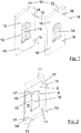
- Figure 1 shows schematically in a perspective view two mold halves 11, 12 of an injection molding tool 10, the two mold halves 11, 12 being shown next to one another for better identification of details, and not in the closing direction 18 of the injection molding tool 10.
- the first mold half 11 is designed as an injection side and shows a first, for example, concave, shaping surface 13 which, for example, forms partial areas of the underside 9 of the foam plastic shoe insert 1 to be produced, if a core part 4 is applied to the outside 5A of a first layer 5 in the injection molding step of the method according to the invention (cf. Figure 2 ) is injected.
- the opposite side, ie the shaping surface 14 of the second mold half 12 is correspondingly, for example, convex and, together with the first shaping surface 13 in the closed state of the injection molding tool 10, forms a cavity which can be filled via the injection point 19.
- the first mold half 11 also has clamping pins 15, on which the first layer 5 can be hung / clamped without folds by means of clamping holes 17 formed therein. When the injection mold 10 is closed in the direction of the closing direction 18, the clamping pins 15 of the first mold half 11 engage in bores 16 which are formed in the second mold half 12.
- the first mold half 11 is shown with a flexible first layer 5 spanned on the receiving pins 15 with a molded-on core part 4, the core part 4 on an outside 5A of the first layer 5 was formed.
- the core part 4 forms part of the underside 9 of the shoe insert 1 in accordance with this exemplary embodiment and can, for example, be individually adapted to the wearer of the shoe insert by a shoe orthopedic technician.
- either the locating pins 15 or the clamping holes 17 are formed in the first layer 5 such that the often three-dimensional design of the core part 4 in the injection molding process is either via a preferably elastic mobility of the locating pins 15 perpendicular to the closing direction or via a Elastic deformability of the material of the first layer 5 takes place, for example the second shaping surface 14 forcing the first layer 5 into a three-dimensional shape when the injection molding tool 10 is closed, before injection plastic is injected into the cavity of the injection mold 10.
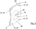
- Figure 3 schematically shows a further embodiment of a flexible first layer 5 with a core part 4 formed thereon in a perspective view, wherein here before the injection molding of the core part 4, a reinforcing layer 30 between the shaping surface of the injection side of the injection molding tool 10- here the mold half 11 - and the side of the flexible first layer 5 is inserted / hooked into the injection molding tool 10, so that this reinforcement layer 30 is attached to the inside 5l of the first layer 5 via the injection molding plastic.
- the reinforcement layer 30 with clamping holes 37 is also hooked into the first mold half 11 of the injection molding tool 10 on the clamping pins 15 of the first mold half 11, the clamping holes 37 of the reinforcement layer 30 preferably matching the clamping holes 17 of the first layer 5.
- these two layers 5, 30, which are connected to one another via the core part 4 can be hooked together for the following process step of RIM foaming via the clamping holes 17 and 37 onto clamping pins 25 of a first mold half 21 of a RIM foam mold 20 and fixed there (see. Figure 4 ).
- the first layer 5 can also be hooked on separately with molded-on core part 4, in particular for those embodiments in which the core part 4 is molded onto the outside 5A of the flexible first layer 5, cf. comments on this Figure 2 .
- the background is that the reinforcement layer 30 is preferably a flexible layer formed from fibers, for example a nonwoven, which is penetrated by the foam plastic in the RIM foaming process and thus reinforces the foam plastic in transverse directions.
- Figure 4 shows two mold halves 21 and 22 of a RIM foam mold 20 in the open state, the two mold halves 21 and 22 analogously to to facilitate the representation of details Figure 1 are arranged side by side.
- the actual closing direction 28 of the RIM foam mold runs in the longitudinal direction of the clamping pins 25.
- Both mold halves 21, 22 of the RIM foam mold 20 have both receiving pins 25 and receiving openings 26 for receiving the receiving pins 25 of the other mold half when the RIM Foam mold 20 is closed.
- the receiving pins 25 of the first mold half 21 are arranged offset to the receiving openings 26 in the first mold half 21, so that when the molding tool 20 is closed, the receiving pins 25 of one mold half 21 or 22 into the receiving openings 26 of the other mold half 22 or 21 can intervene.
- the first flexible layer 5 can be constructed from a fiber-containing material which is permeable to both the injection molded plastic and the foam plastic - at least in its uncured form.
- the first layer 5 can thus take over the function of a reinforcing layer 30; In this case, however, it is only suitable as a false ceiling 3 if the underside 9 of the shoe insert 1 is to be free of PU foam.
- a second layer 6 as a material layer for a false ceiling 3 lends itself, which is then inserted between a shaping surface 23 of a first foam mold half 21 of an RIM foam mold 20 and the first layer 5 and preferably at least one impermeable to the PU foam plastic Layer. It is not necessary for the first layer 5 and the second layer 6 to be connected to one another via the injection-molded core part 4.
- the foam plastic produced in the closed foam mold 20 swells within the cavity of the foam mold 20 through areas of the first layer 5 that are not stiffened by the core part 4 and at least wets the areas of the inner side 6l of the second layer 6 that are not shadowed by the core part 4 Connection of the first layer 5 with the second layer 6 made via the foam plastic.
- the shaping surface 24 preferably delimits the cavity of the foam mold 20 such that an orthopedic footbed is formed on the top 8 of the shoe insert 1, the side of the first layer 5 facing the shaping surface 24 preferably being completely covered with foam plastic is.
- a top cover 2 can then be applied to this orthopedic footbed in a further step, if necessary after individual adjustment of the footbed.
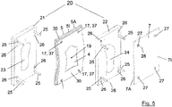
- Figure 5 likewise does not show an embodiment to scale with a third layer 7 which can be connected to the top cover 2 in RIM foaming step.
- Figure 4 is the false ceiling 2 by the first layer 5 according to the embodiment of the above described Figure 3 formed, to which a reinforcing layer 30 was also previously attached by injection molding when the core part 4 was molded onto the first layer 5.
- the individual layers are in the Figure 5 shown spaced from the respective mold halves 21, 22.
- a core part 4 is formed on the inside of the first layer 5, the outside 5A of the first layer 5, which later becomes the underside 9 of the shoe insert, since it forms the shaping surface 23 of the first mold half 21 of the RIM foam mold 20 is facing.
- the molded-on core part 4 is formed on the inside 5l of the first layer 5 facing away from the shaping surface 23 and is spanned with a reinforcing layer 30.
- the core part will be covered on the finished shoe insert 1 after the foaming process.
- a two-layer material was selected as the material for the first layer 5, the inside of which is a fabric-like textile, which is firmly connected to the injection-molded core part 4.
- the outside 5A of the first layer 5 is formed by a barrier layer 5U which is impermeable to the uncured foam plastic and which has not necessarily entered into a connection with the injection molding material.
- the material of the barrier layer 5U, which forms the underside 9 of the later foam plastic shoe insert 1 is an elastic, in particular rubber-like material, which gives the shoe insert a non-slip underside 9 so that the foam plastic shoe insert 1 is inserted into a shoe, for example non-slip can be.
- a third layer 7 is stretched over the second mold half 22 of the RIM foam mold 20 (here the right mold half 22) over the shaping surface 24. This takes place analogously to the clamping of the first layer 5 in front of the shaping surface 23 of the first mold half 21.
- a foam plastic impermeable barrier layer can also be on or in the third layer 7 7U be arranged. For example, if a multilayer material is used for the third layer 7 and the inside 7l is formed from a material that is permeable to the foam plastic.
- foam plastic reaches the top 8 of the shoe insert 1
- a foam plastic barrier layer 7U can be arranged.
- the foam plastic that forms can connect to the inner sides 5l and 7l of the first layer 5 and the third layer 7 and at the same time form a foam plastic shoe insert blank 100 with an orthopedic footbed by expanding the foam plastic in the cavity formed by the foam mold half.
- the foam plastic forms part or all of the cushion body 31 of the foam plastic shoe insert.
- a blank insert 100 can be removed from the RIM foam mold 20, which has both a bottom cover 9 and a top cover 8 with a blanket 3 or an upper ceiling 2 is covered, both ceilings being connected to one another by means of the foamed PU foam plastic.
- FIG Figure 6 A shoe insert blank 100 removed from the RIM foam mold 20 is shown in FIG Figure 6 , shown in a schematic representation which, for the sake of clarity, shows only one left shoe insert blank 100.
- FIG Figure 6 Foam plastic shoe insert blank 100 shown is a core part 4 formed on the outside 5A of the first layer 5, that is to say also on the underside 9 of the shoe insert 1, which extends from the metatarsal region 45 to the heel region 40.
- a recess 41 is provided in the core part 4, which is filled with PU foam plastic, in order, for example, to better dampen the heel spur of the wearer of the shoe insert 1.
- the area surrounding the recess 41 is further supported by the sole-stabilizing core part 4. It is readily apparent to a person skilled in the art that the core part 4 can also be extended to other areas, such as the forefoot area 50 or the toe area 55, wherein there may also be recesses in the core part 4 and / or in the first layer 5, which also have Foam plastic are filled.
- the method according to the invention also forms additional core parts or orthopedic aids, such as pelottes or the like, for example in the region of the basic toe joints, by injection molding onto the first layer 5 or onto the second layer 6 or the third layer 7 before the RIM.
- additional core parts or orthopedic aids such as pelottes or the like, for example in the region of the basic toe joints, by injection molding onto the first layer 5 or onto the second layer 6 or the third layer 7 before the RIM.
- Foaming processes can be applied without deviating from the inventive concept.
- pads are preferably formed directly in the RIM foaming step by the foam plastic produced there and then do not have to be attached to the respective layer 5, 6 or 7 as individual parts.
- it allows the insertion of pads or similar orthopedic aids a stronger individualization of the shoe inserts produced according to the invention.
- the in Figure 6 shown shoe insert blank 100 can only be custom-tailored in its shape / contour, which is preferably done by punching, but can also be done manually.
- finished foam plastic shoe insert 1 means that it is ready for use to the extent that it can either be inserted directly into a shoe or can also be made available to a shoe orthopedist so that the foam plastic shoe insert 1 can be individually fitted to the wearer of the Can adjust shoe insert.
- a simple and robust manufacturing method is provided, with which high-quality, possibly individually adaptable shoe inserts can be produced.
- the costly and high-precision process steps are avoided, at least for covering a blank PU foam plastic with a false ceiling and / or a ceiling.
- a thin shoe insert 1 can be produced which only minimally affects the biometric conditions of a shoe into which the shoe insert 1 according to the invention is to be inserted.
Landscapes
- Engineering & Computer Science (AREA)
- Health & Medical Sciences (AREA)
- General Health & Medical Sciences (AREA)
- Mechanical Engineering (AREA)
- Life Sciences & Earth Sciences (AREA)
- Public Health (AREA)
- Epidemiology (AREA)
- Wood Science & Technology (AREA)
- Materials Engineering (AREA)
- Chemical & Material Sciences (AREA)
- Orthopedic Medicine & Surgery (AREA)
- Animal Behavior & Ethology (AREA)
- Veterinary Medicine (AREA)
- Vascular Medicine (AREA)
- Heart & Thoracic Surgery (AREA)
- Biomedical Technology (AREA)
- Nursing (AREA)
- Footwear And Its Accessory, Manufacturing Method And Apparatuses (AREA)
Priority Applications (6)
| Application Number | Priority Date | Filing Date | Title |
|---|---|---|---|
| EP18152947.0A EP3513675B1 (de) | 2018-01-23 | 2018-01-23 | Orthopädische schaumkunststoff-schuheinlage |
| ES18152947T ES2808142T3 (es) | 2018-01-23 | 2018-01-23 | Plantilla ortopédica de plástico espumado para zapato |
| LTEP18152947.0T LT3513675T (lt) | 2018-01-23 | 2018-01-23 | Ortopedinis putplasčio batų įdėklas |
| PL18152947T PL3513675T3 (pl) | 2018-01-23 | 2018-01-23 | Ortopedyczne wkładki do butów z tworzywa piankowego |
| CN201910042456.7A CN110065253B (zh) | 2018-01-23 | 2019-01-16 | 矫形泡沫合成材料鞋垫 |
| RU2019101627A RU2717208C1 (ru) | 2018-01-23 | 2019-01-22 | Ортопедическая поропластовая стелька |
Applications Claiming Priority (1)
| Application Number | Priority Date | Filing Date | Title |
|---|---|---|---|
| EP18152947.0A EP3513675B1 (de) | 2018-01-23 | 2018-01-23 | Orthopädische schaumkunststoff-schuheinlage |
Publications (2)
| Publication Number | Publication Date |
|---|---|
| EP3513675A1 EP3513675A1 (de) | 2019-07-24 |
| EP3513675B1 true EP3513675B1 (de) | 2020-05-13 |
Family
ID=61027474
Family Applications (1)
| Application Number | Title | Priority Date | Filing Date |
|---|---|---|---|
| EP18152947.0A Active EP3513675B1 (de) | 2018-01-23 | 2018-01-23 | Orthopädische schaumkunststoff-schuheinlage |
Country Status (6)
| Country | Link |
|---|---|
| EP (1) | EP3513675B1 (pl) |
| CN (1) | CN110065253B (pl) |
| ES (1) | ES2808142T3 (pl) |
| LT (1) | LT3513675T (pl) |
| PL (1) | PL3513675T3 (pl) |
| RU (1) | RU2717208C1 (pl) |
Cited By (1)
| Publication number | Priority date | Publication date | Assignee | Title |
|---|---|---|---|---|
| EP3981279A1 (de) | 2020-10-09 | 2022-04-13 | Spannrit GmbH | Orthopädischer schuheinlage-rohling und verfahren zu dessen herstellung |
Families Citing this family (2)
| Publication number | Priority date | Publication date | Assignee | Title |
|---|---|---|---|---|
| ES3015087T3 (en) * | 2022-10-10 | 2025-04-29 | Spannrit Gmbh | Orthopaedic pur foam plastic shoe insole blank |
| EP4643701A1 (de) * | 2024-04-30 | 2025-11-05 | Allein Holding GmbH | Deckenmaterial für schuheinlegesohlen, schuheinlegesohle mit einem solchen deckenmaterial und herstellverfahren eines bzw. einer solchen |
Family Cites Families (9)
| Publication number | Priority date | Publication date | Assignee | Title |
|---|---|---|---|---|
| RU2129822C1 (ru) * | 1998-04-21 | 1999-05-10 | Санкт-Петербургский государственный университет технологии и дизайна | Вкладная стелька для обуви |
| ATE311286T1 (de) * | 2003-09-17 | 2005-12-15 | Spannrit Schuhkomponenten Gmbh | Verfahren zur herstellung einer orthopädischen schuheinlage und nach dem verfahren hergestellte schuheinlage |
| EP1602294B1 (de) | 2004-06-02 | 2008-03-05 | Spannrit Schuhkomponenten GmbH | Polyurethan-Schaum-Einlegesohle und Verfahren zu ihrer Herstellung |
| EP1967086B1 (de) | 2007-03-05 | 2010-10-20 | Spannrit Schuhkomponenten GmbH | Schaumkunststoff-Schuheinlegesohle |
| SI2218349T1 (sl) * | 2009-02-13 | 2012-01-31 | Spannrit Schuhkomponenten Gmbh | VloĹľek za ÄŤevelj z gelom |
| RU148057U1 (ru) * | 2013-09-25 | 2014-11-20 | Спаннрит Шухкомпонентен ГмбХ | Ортопедическая стелька-супинатор |
| EP2910677B1 (de) * | 2014-02-21 | 2016-05-25 | Spannrit Schuhkomponenten GmbH | Bedruckte schaumkunststoff-schuheinlegesohlen-rohlinge |
| SI2918185T1 (en) * | 2014-03-11 | 2018-01-31 | Spannrit Gmbh | Rubber for shoes for shoes made from foam plastic material |
| RU2671118C1 (ru) * | 2018-06-06 | 2018-10-29 | Андрей Васильевич Дерягин | Ортопедическая стелька |
-
2018
- 2018-01-23 ES ES18152947T patent/ES2808142T3/es active Active
- 2018-01-23 PL PL18152947T patent/PL3513675T3/pl unknown
- 2018-01-23 EP EP18152947.0A patent/EP3513675B1/de active Active
- 2018-01-23 LT LTEP18152947.0T patent/LT3513675T/lt unknown
-
2019
- 2019-01-16 CN CN201910042456.7A patent/CN110065253B/zh active Active
- 2019-01-22 RU RU2019101627A patent/RU2717208C1/ru active
Non-Patent Citations (1)
| Title |
|---|
| None * |
Cited By (1)
| Publication number | Priority date | Publication date | Assignee | Title |
|---|---|---|---|---|
| EP3981279A1 (de) | 2020-10-09 | 2022-04-13 | Spannrit GmbH | Orthopädischer schuheinlage-rohling und verfahren zu dessen herstellung |
Also Published As
| Publication number | Publication date |
|---|---|
| LT3513675T (lt) | 2020-09-10 |
| RU2717208C1 (ru) | 2020-03-18 |
| ES2808142T3 (es) | 2021-02-25 |
| PL3513675T3 (pl) | 2020-11-02 |
| EP3513675A1 (de) | 2019-07-24 |
| CN110065253B (zh) | 2022-05-27 |
| CN110065253A (zh) | 2019-07-30 |
Similar Documents
| Publication | Publication Date | Title |
|---|---|---|
| EP3513675B1 (de) | Orthopädische schaumkunststoff-schuheinlage | |
| DE19851117C5 (de) | Verfahren zum Herstellen eines Formteils | |
| EP1602294B1 (de) | Polyurethan-Schaum-Einlegesohle und Verfahren zu ihrer Herstellung | |
| EP2298606A1 (de) | Innenverkleidungsteil für einen Fahrgastraum eines Fahrzeugs sowie Verfahren zur seiner Herstellung | |
| EP2241207B1 (de) | Schaumkunststoff-Schuheinlegesohlen-Rohling | |
| EP2042291B1 (de) | Verfahren zur Herstellung eines Formteils und Formteil | |
| DE102004021337B4 (de) | Verfahren zur Herstellung eines Verbund-Karosserieteils für ein Fahrzeug | |
| WO2007000174A9 (de) | Verfahren und werkzeug zur herstellung eines bauteils aus kunststoff mit einer dekorations-schicht und einer träger-schicht mit einem zusätzlich an dieser angeordneten formeil | |
| WO2023198487A1 (de) | Verfahren zur herstellung eines unterbaus für schuhwaren schuhware und maschine zur herstellung eines unterbaus | |
| EP3981279B1 (de) | Orthopädischer schuheinlage-rohling und verfahren zu dessen herstellung | |
| EP0061505B1 (de) | Verfahren zur Herstellung einer Polsterbrand- oder Einlegesohle | |
| DE102018206906B4 (de) | Einlegesohlen-Fräsblock und Verfahren zum Herstellen eines solchen Fräsblocks | |
| EP2910677B1 (de) | Bedruckte schaumkunststoff-schuheinlegesohlen-rohlinge | |
| EP0893112A1 (de) | Orthopädisches Stützteil | |
| EP0443121B1 (de) | yrthopädische Schuheinlage | |
| EP3463974B1 (de) | Sitzlehnenverkleidung und verfahren zu deren herstellung | |
| EP4353115B1 (de) | Orthopädischer pur-schaumkunststoff-schuheinlegesohlenrohling | |
| DE10234653B4 (de) | Mehrdimensionale Verbundanordnung, Verwendung dieser sowie ein Herstellungsverfahren für eine Verbundanordnung | |
| DE10008775C1 (de) | Verfahren zur Herstellung eines Kunststoff-Verbundelements, insbesondere eines Innenverkleidungselements für ein Kraftfahrzeug, sowie ein solches Kunststoff- Verbundelement | |
| EP2823956B1 (de) | Schaumkunststoff-Schuheinlegesohle mit textiler Lage und Verfahren zu deren Herstellung | |
| EP4070681B1 (de) | Orthopädischer schuheinlegesohlenrohling | |
| DE10102345C1 (de) | Deckelement und Modulsystem zur Herstellung von Schuheinlagen | |
| DE19854536B4 (de) | Verfahren zur Herstellung eines orthopädischen Stützteils | |
| AT513141B1 (de) | Verfahren zur Herstellung einer kombinierten Brandsohle | |
| DE3701950C2 (pl) |
Legal Events
| Date | Code | Title | Description |
|---|---|---|---|
| STAA | Information on the status of an ep patent application or granted ep patent |
Free format text: STATUS: EXAMINATION IS IN PROGRESS |
|
| PUAI | Public reference made under article 153(3) epc to a published international application that has entered the european phase |
Free format text: ORIGINAL CODE: 0009012 |
|
| 17P | Request for examination filed |
Effective date: 20181115 |
|
| AK | Designated contracting states |
Kind code of ref document: A1 Designated state(s): AL AT BE BG CH CY CZ DE DK EE ES FI FR GB GR HR HU IE IS IT LI LT LU LV MC MK MT NL NO PL PT RO RS SE SI SK SM TR |
|
| AX | Request for extension of the european patent |
Extension state: BA ME |
|
| GRAP | Despatch of communication of intention to grant a patent |
Free format text: ORIGINAL CODE: EPIDOSNIGR1 |
|
| STAA | Information on the status of an ep patent application or granted ep patent |
Free format text: STATUS: GRANT OF PATENT IS INTENDED |
|
| INTG | Intention to grant announced |
Effective date: 20191211 |
|
| GRAS | Grant fee paid |
Free format text: ORIGINAL CODE: EPIDOSNIGR3 |
|
| GRAA | (expected) grant |
Free format text: ORIGINAL CODE: 0009210 |
|
| STAA | Information on the status of an ep patent application or granted ep patent |
Free format text: STATUS: THE PATENT HAS BEEN GRANTED |
|
| AK | Designated contracting states |
Kind code of ref document: B1 Designated state(s): AL AT BE BG CH CY CZ DE DK EE ES FI FR GB GR HR HU IE IS IT LI LT LU LV MC MK MT NL NO PL PT RO RS SE SI SK SM TR |
|
| REG | Reference to a national code |
Ref country code: GB Ref legal event code: FG4D Free format text: NOT ENGLISH |
|
| REG | Reference to a national code |
Ref country code: CH Ref legal event code: EP |
|
| REG | Reference to a national code |
Ref country code: DE Ref legal event code: R096 Ref document number: 502018001352 Country of ref document: DE |
|
| REG | Reference to a national code |
Ref country code: AT Ref legal event code: REF Ref document number: 1269056 Country of ref document: AT Kind code of ref document: T Effective date: 20200615 |
|
| REG | Reference to a national code |
Ref country code: NL Ref legal event code: MP Effective date: 20200513 |
|
| PG25 | Lapsed in a contracting state [announced via postgrant information from national office to epo] |
Ref country code: GR Free format text: LAPSE BECAUSE OF FAILURE TO SUBMIT A TRANSLATION OF THE DESCRIPTION OR TO PAY THE FEE WITHIN THE PRESCRIBED TIME-LIMIT Effective date: 20200814 Ref country code: NO Free format text: LAPSE BECAUSE OF FAILURE TO SUBMIT A TRANSLATION OF THE DESCRIPTION OR TO PAY THE FEE WITHIN THE PRESCRIBED TIME-LIMIT Effective date: 20200813 Ref country code: IS Free format text: LAPSE BECAUSE OF FAILURE TO SUBMIT A TRANSLATION OF THE DESCRIPTION OR TO PAY THE FEE WITHIN THE PRESCRIBED TIME-LIMIT Effective date: 20200913 Ref country code: PT Free format text: LAPSE BECAUSE OF FAILURE TO SUBMIT A TRANSLATION OF THE DESCRIPTION OR TO PAY THE FEE WITHIN THE PRESCRIBED TIME-LIMIT Effective date: 20200914 Ref country code: FI Free format text: LAPSE BECAUSE OF FAILURE TO SUBMIT A TRANSLATION OF THE DESCRIPTION OR TO PAY THE FEE WITHIN THE PRESCRIBED TIME-LIMIT Effective date: 20200513 Ref country code: SE Free format text: LAPSE BECAUSE OF FAILURE TO SUBMIT A TRANSLATION OF THE DESCRIPTION OR TO PAY THE FEE WITHIN THE PRESCRIBED TIME-LIMIT Effective date: 20200513 |
|
| REG | Reference to a national code |
Ref country code: SK Ref legal event code: T3 Ref document number: E 34988 Country of ref document: SK |
|
| PG25 | Lapsed in a contracting state [announced via postgrant information from national office to epo] |
Ref country code: HR Free format text: LAPSE BECAUSE OF FAILURE TO SUBMIT A TRANSLATION OF THE DESCRIPTION OR TO PAY THE FEE WITHIN THE PRESCRIBED TIME-LIMIT Effective date: 20200513 Ref country code: BG Free format text: LAPSE BECAUSE OF FAILURE TO SUBMIT A TRANSLATION OF THE DESCRIPTION OR TO PAY THE FEE WITHIN THE PRESCRIBED TIME-LIMIT Effective date: 20200813 Ref country code: RS Free format text: LAPSE BECAUSE OF FAILURE TO SUBMIT A TRANSLATION OF THE DESCRIPTION OR TO PAY THE FEE WITHIN THE PRESCRIBED TIME-LIMIT Effective date: 20200513 |
|
| PG25 | Lapsed in a contracting state [announced via postgrant information from national office to epo] |
Ref country code: AL Free format text: LAPSE BECAUSE OF FAILURE TO SUBMIT A TRANSLATION OF THE DESCRIPTION OR TO PAY THE FEE WITHIN THE PRESCRIBED TIME-LIMIT Effective date: 20200513 Ref country code: NL Free format text: LAPSE BECAUSE OF FAILURE TO SUBMIT A TRANSLATION OF THE DESCRIPTION OR TO PAY THE FEE WITHIN THE PRESCRIBED TIME-LIMIT Effective date: 20200513 |
|
| PG25 | Lapsed in a contracting state [announced via postgrant information from national office to epo] |
Ref country code: IT Free format text: LAPSE BECAUSE OF FAILURE TO SUBMIT A TRANSLATION OF THE DESCRIPTION OR TO PAY THE FEE WITHIN THE PRESCRIBED TIME-LIMIT Effective date: 20200513 Ref country code: SM Free format text: LAPSE BECAUSE OF FAILURE TO SUBMIT A TRANSLATION OF THE DESCRIPTION OR TO PAY THE FEE WITHIN THE PRESCRIBED TIME-LIMIT Effective date: 20200513 Ref country code: DK Free format text: LAPSE BECAUSE OF FAILURE TO SUBMIT A TRANSLATION OF THE DESCRIPTION OR TO PAY THE FEE WITHIN THE PRESCRIBED TIME-LIMIT Effective date: 20200513 Ref country code: EE Free format text: LAPSE BECAUSE OF FAILURE TO SUBMIT A TRANSLATION OF THE DESCRIPTION OR TO PAY THE FEE WITHIN THE PRESCRIBED TIME-LIMIT Effective date: 20200513 |
|
| REG | Reference to a national code |
Ref country code: DE Ref legal event code: R097 Ref document number: 502018001352 Country of ref document: DE |
|
| REG | Reference to a national code |
Ref country code: ES Ref legal event code: FG2A Ref document number: 2808142 Country of ref document: ES Kind code of ref document: T3 Effective date: 20210225 |
|
| PLBE | No opposition filed within time limit |
Free format text: ORIGINAL CODE: 0009261 |
|
| STAA | Information on the status of an ep patent application or granted ep patent |
Free format text: STATUS: NO OPPOSITION FILED WITHIN TIME LIMIT |
|
| 26N | No opposition filed |
Effective date: 20210216 |
|
| PG25 | Lapsed in a contracting state [announced via postgrant information from national office to epo] |
Ref country code: SI Free format text: LAPSE BECAUSE OF FAILURE TO SUBMIT A TRANSLATION OF THE DESCRIPTION OR TO PAY THE FEE WITHIN THE PRESCRIBED TIME-LIMIT Effective date: 20200513 |
|
| REG | Reference to a national code |
Ref country code: DE Ref legal event code: R082 Ref document number: 502018001352 Country of ref document: DE Representative=s name: KUHNEN & WACKER PATENT- UND RECHTSANWALTSBUERO, DE |
|
| PG25 | Lapsed in a contracting state [announced via postgrant information from national office to epo] |
Ref country code: MC Free format text: LAPSE BECAUSE OF FAILURE TO SUBMIT A TRANSLATION OF THE DESCRIPTION OR TO PAY THE FEE WITHIN THE PRESCRIBED TIME-LIMIT Effective date: 20200513 |
|
| REG | Reference to a national code |
Ref country code: CH Ref legal event code: PL |
|
| PG25 | Lapsed in a contracting state [announced via postgrant information from national office to epo] |
Ref country code: LU Free format text: LAPSE BECAUSE OF NON-PAYMENT OF DUE FEES Effective date: 20210123 |
|
| REG | Reference to a national code |
Ref country code: BE Ref legal event code: MM Effective date: 20210131 |
|
| PG25 | Lapsed in a contracting state [announced via postgrant information from national office to epo] |
Ref country code: FR Free format text: LAPSE BECAUSE OF NON-PAYMENT OF DUE FEES Effective date: 20210131 |
|
| PG25 | Lapsed in a contracting state [announced via postgrant information from national office to epo] |
Ref country code: LI Free format text: LAPSE BECAUSE OF NON-PAYMENT OF DUE FEES Effective date: 20210131 Ref country code: CH Free format text: LAPSE BECAUSE OF NON-PAYMENT OF DUE FEES Effective date: 20210131 |
|
| PG25 | Lapsed in a contracting state [announced via postgrant information from national office to epo] |
Ref country code: IE Free format text: LAPSE BECAUSE OF NON-PAYMENT OF DUE FEES Effective date: 20210123 |
|
| PG25 | Lapsed in a contracting state [announced via postgrant information from national office to epo] |
Ref country code: BE Free format text: LAPSE BECAUSE OF NON-PAYMENT OF DUE FEES Effective date: 20210131 |
|
| P01 | Opt-out of the competence of the unified patent court (upc) registered |
Effective date: 20230516 |
|
| PG25 | Lapsed in a contracting state [announced via postgrant information from national office to epo] |
Ref country code: CY Free format text: LAPSE BECAUSE OF FAILURE TO SUBMIT A TRANSLATION OF THE DESCRIPTION OR TO PAY THE FEE WITHIN THE PRESCRIBED TIME-LIMIT Effective date: 20200513 |
|
| PG25 | Lapsed in a contracting state [announced via postgrant information from national office to epo] |
Ref country code: HU Free format text: LAPSE BECAUSE OF FAILURE TO SUBMIT A TRANSLATION OF THE DESCRIPTION OR TO PAY THE FEE WITHIN THE PRESCRIBED TIME-LIMIT; INVALID AB INITIO Effective date: 20180123 |
|
| PG25 | Lapsed in a contracting state [announced via postgrant information from national office to epo] |
Ref country code: RO Free format text: LAPSE BECAUSE OF NON-PAYMENT OF DUE FEES Effective date: 20230123 |
|
| PG25 | Lapsed in a contracting state [announced via postgrant information from national office to epo] |
Ref country code: MK Free format text: LAPSE BECAUSE OF FAILURE TO SUBMIT A TRANSLATION OF THE DESCRIPTION OR TO PAY THE FEE WITHIN THE PRESCRIBED TIME-LIMIT Effective date: 20200513 |
|
| PG25 | Lapsed in a contracting state [announced via postgrant information from national office to epo] |
Ref country code: MT Free format text: LAPSE BECAUSE OF FAILURE TO SUBMIT A TRANSLATION OF THE DESCRIPTION OR TO PAY THE FEE WITHIN THE PRESCRIBED TIME-LIMIT Effective date: 20200513 |
|
| PG25 | Lapsed in a contracting state [announced via postgrant information from national office to epo] |
Ref country code: TR Free format text: LAPSE BECAUSE OF FAILURE TO SUBMIT A TRANSLATION OF THE DESCRIPTION OR TO PAY THE FEE WITHIN THE PRESCRIBED TIME-LIMIT Effective date: 20200513 |
|
| PGFP | Annual fee paid to national office [announced via postgrant information from national office to epo] |
Ref country code: LT Payment date: 20251201 Year of fee payment: 9 |
|
| PGFP | Annual fee paid to national office [announced via postgrant information from national office to epo] |
Ref country code: CZ Payment date: 20251014 Year of fee payment: 9 |
|
| PGFP | Annual fee paid to national office [announced via postgrant information from national office to epo] |
Ref country code: LV Payment date: 20251014 Year of fee payment: 9 |
|
| PGFP | Annual fee paid to national office [announced via postgrant information from national office to epo] |
Ref country code: PL Payment date: 20251105 Year of fee payment: 9 |
|
| PGFP | Annual fee paid to national office [announced via postgrant information from national office to epo] |
Ref country code: SK Payment date: 20251014 Year of fee payment: 9 |
|
| PGFP | Annual fee paid to national office [announced via postgrant information from national office to epo] |
Ref country code: GB Payment date: 20260127 Year of fee payment: 9 |
|
| PGFP | Annual fee paid to national office [announced via postgrant information from national office to epo] |
Ref country code: ES Payment date: 20260202 Year of fee payment: 9 |
|
| PGFP | Annual fee paid to national office [announced via postgrant information from national office to epo] |
Ref country code: DE Payment date: 20251105 Year of fee payment: 9 |
|
| PGFP | Annual fee paid to national office [announced via postgrant information from national office to epo] |
Ref country code: AT Payment date: 20251114 Year of fee payment: 9 |
|
| PGFP | Annual fee paid to national office [announced via postgrant information from national office to epo] |
Ref country code: RO Payment date: 20260120 Year of fee payment: 9 |