EP3513644B1 - Mähroboter - Google Patents
Mähroboter Download PDFInfo
- Publication number
- EP3513644B1 EP3513644B1 EP19152518.7A EP19152518A EP3513644B1 EP 3513644 B1 EP3513644 B1 EP 3513644B1 EP 19152518 A EP19152518 A EP 19152518A EP 3513644 B1 EP3513644 B1 EP 3513644B1
- Authority
- EP
- European Patent Office
- Prior art keywords
- motor
- disposed
- wheel
- sensor
- blade
- Prior art date
- Legal status (The legal status is an assumption and is not a legal conclusion. Google has not performed a legal analysis and makes no representation as to the accuracy of the status listed.)
- Active
Links
Images


Classifications
-
- A—HUMAN NECESSITIES
- A01—AGRICULTURE; FORESTRY; ANIMAL HUSBANDRY; HUNTING; TRAPPING; FISHING
- A01D—HARVESTING; MOWING
- A01D34/00—Mowers; Mowing apparatus of harvesters
- A01D34/01—Mowers; Mowing apparatus of harvesters characterised by features relating to the type of cutting apparatus
- A01D34/412—Mowers; Mowing apparatus of harvesters characterised by features relating to the type of cutting apparatus having rotating cutters
- A01D34/63—Mowers; Mowing apparatus of harvesters characterised by features relating to the type of cutting apparatus having rotating cutters having cutters rotating about a vertical axis
-
- A—HUMAN NECESSITIES
- A01—AGRICULTURE; FORESTRY; ANIMAL HUSBANDRY; HUNTING; TRAPPING; FISHING
- A01D—HARVESTING; MOWING
- A01D34/00—Mowers; Mowing apparatus of harvesters
- A01D34/006—Control or measuring arrangements
- A01D34/008—Control or measuring arrangements for automated or remotely controlled operation
-
- A—HUMAN NECESSITIES
- A01—AGRICULTURE; FORESTRY; ANIMAL HUSBANDRY; HUNTING; TRAPPING; FISHING
- A01D—HARVESTING; MOWING
- A01D34/00—Mowers; Mowing apparatus of harvesters
- A01D34/001—Accessories not otherwise provided for
-
- A—HUMAN NECESSITIES
- A01—AGRICULTURE; FORESTRY; ANIMAL HUSBANDRY; HUNTING; TRAPPING; FISHING
- A01D—HARVESTING; MOWING
- A01D34/00—Mowers; Mowing apparatus of harvesters
- A01D34/006—Control or measuring arrangements
-
- A—HUMAN NECESSITIES
- A01—AGRICULTURE; FORESTRY; ANIMAL HUSBANDRY; HUNTING; TRAPPING; FISHING
- A01D—HARVESTING; MOWING
- A01D34/00—Mowers; Mowing apparatus of harvesters
- A01D34/01—Mowers; Mowing apparatus of harvesters characterised by features relating to the type of cutting apparatus
- A01D34/412—Mowers; Mowing apparatus of harvesters characterised by features relating to the type of cutting apparatus having rotating cutters
- A01D34/42—Mowers; Mowing apparatus of harvesters characterised by features relating to the type of cutting apparatus having rotating cutters having cutters rotating about a horizontal axis, e.g. cutting-cylinders
- A01D34/56—Driving mechanisms for the cutters
- A01D34/58—Driving mechanisms for the cutters electric
-
- B—PERFORMING OPERATIONS; TRANSPORTING
- B25—HAND TOOLS; PORTABLE POWER-DRIVEN TOOLS; MANIPULATORS
- B25J—MANIPULATORS; CHAMBERS PROVIDED WITH MANIPULATION DEVICES
- B25J11/00—Manipulators not otherwise provided for
-
- B—PERFORMING OPERATIONS; TRANSPORTING
- B25—HAND TOOLS; PORTABLE POWER-DRIVEN TOOLS; MANIPULATORS
- B25J—MANIPULATORS; CHAMBERS PROVIDED WITH MANIPULATION DEVICES
- B25J13/00—Controls for manipulators
- B25J13/08—Controls for manipulators by means of sensing devices, e.g. viewing or touching devices
- B25J13/088—Controls for manipulators by means of sensing devices, e.g. viewing or touching devices with position, velocity or acceleration sensors
-
- B—PERFORMING OPERATIONS; TRANSPORTING
- B25—HAND TOOLS; PORTABLE POWER-DRIVEN TOOLS; MANIPULATORS
- B25J—MANIPULATORS; CHAMBERS PROVIDED WITH MANIPULATION DEVICES
- B25J5/00—Manipulators mounted on wheels or on carriages
- B25J5/007—Manipulators mounted on wheels or on carriages mounted on wheels
-
- A—HUMAN NECESSITIES
- A01—AGRICULTURE; FORESTRY; ANIMAL HUSBANDRY; HUNTING; TRAPPING; FISHING
- A01D—HARVESTING; MOWING
- A01D2101/00—Lawn-mowers
Definitions
- the present invention relates to a sensor disposition structure of a mowing robot.
- Robots have been developed for industrial use and have been part of factory automation. Recently, the application field of robot has been expanded such that medical robot, aerospace robot, and the like have been developed and household robot that can be used in ordinary homes has been made. Among these robots, a robot capable of traveling by itself is called a mobile robot. A typical example of the mobile robot used in the outdoor environment of a home is a mowing robot.
- a movable area In the case of a mobile robot that autonomously travels indoors, a movable area is restricted by a wall, furniture, or the like. However, in the case of the mowing robot that autonomously travels outdoors, it is required to previously set the movable area. In addition, it is required to restrict the movable area so that the mowing robot can travel in the area where lawns are planted.
- the mowing robot travels outdoors unlike a cleaning robot that travels indoors, it is difficult to check a position through the surrounding image, and the role of the gyro sensing function and the acceleration sensing function is important.
- a first object of the present invention is to use a sensor having both a gyro sensing function and a magnetic field sensing function in a mowing robot for cost reduction and to solve a problem of using such a sensor. Further, when the sensor has a gyro sensing function, a magnetic field sensing function, and an acceleration sensing function, it is to solve a problem of using such a sensor.
- a second object of the present invention is to make it possible that the result of gyroscopic sensing of the sensor more effectively reflects the actual rotation result of a mobile robot, and further the combined result of the gyro sensing result and the acceleration sensing result of the sensor more effectively reflects the actual movement result of the mobile robot.
- a third object of the present invention is to reduce the influence of the magnetic field generated by other parts of the mowing robot on the magnetic field sensing result of the sensor while achieving the first object and second object of the present invention, so that the external magnetic field can be more accurately sensed by the sensor.
- a mowing robot includes: a body which forms an outer shape and an internal space; a first wheel and a second wheel which are independently rotatably provided in a left side and a right side respectively so that the body can rotate and move forward with respect to ground; a first motor which provides a rotational force of the first wheel; a second motor which provides a rotational force of the second wheel; and a sensor which is disposed in the internal space, has a gyro sensing function for at least horizontal rotation, and has a magnetic field sensing function, when i) a virtual wheel front end plane which is in contact with a front end of the first wheel and a front end of the second wheel and is vertically disposed; ii) a virtual wheel rear end plane which is in contact with a rear end of the first wheel and a rear end of the second wheel and is vertically disposed; iii) a virtual first motor upper end plane which is in contact with an upper end of the first motor and is horizontally
- the mowing robot further includes a cover, to which the sensor is fixed, that fully covers the sensor when viewed from the first motor and fully covers the sensor when viewed from the second motor. Further, the cover is configured to reduce the magnetic field influence of the first motor and the second motor on the sensor.
- the sensor may be disposed closest to a virtual wheel axis plane, among the wheel front end plane, the wheel rear end plane, and the wheel axis plane which passes through a center of the first wheel and a center of the second wheel and is disposed vertically.
- the mowing robot may further include: a blade which is disposed in front of a center of the first wheel and a center of the second wheel and is rotatably provided for mowing; a blade motor which provides a rotational force of the blade; and a battery which is disposed behind the center of the first wheel and the center of the second wheel and provides power to the first motor, the second motor, and the blade motor, and the sensor is disposed in an upper side portion of the internal space, and the first motor, the second motor, the blade motor, and the battery are disposed in a lower side portion of the internal space.
- the mowing robot may further include a battery which is disposed in a center of the first wheel and a center of the second wheel and provides power to the first motor and the second motor, and the sensor is disposed in front of a virtual battery front end plane which is in contact with a front end of the battery and is vertically disposed, and disposed in an upper side of a virtual battery upper end plane which is in contact with an upper end of the battery and is horizontally disposed.
- the sensor may be disposed in an upper side of a virtual blade motor upper end plane which is in contact with an upper end of the blade motor and is horizontally disposed, and is disposed in an upper side of a virtual battery upper end plane which is in contact with an upper end of the battery and is horizontally disposed.
- the cover may fully cover the sensor when viewed from below.
- the mowing robot may further include a main board which is disposed in an upper side of the first motor and the second motor, disposed in a lower side of the cover, fully covers the sensor when viewed from below, and controls a driving of the first motor and the second motor.
- the mowing robot may further include a covering supporting unit which fixes the cover to the main board while spacing the cover from the main board.
- the mowing robot may further include: a module case which is disposed inside the body, and accommodates the sensor, the cover, and the main board therein; and a display module which is disposed in an upper side of the sensor, and fixed to an upper side portion of the module case.
- first, second, etc. in front of the constituent elements mentioned in the lower side of is intended to avoid confusion of the constituent elements, and is not related to the order, importance, master-servant relationship, or the like between the constituent elements.
- an invention including only a second constituent element without a first constituent element can be implemented.
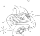
- the wheel axis Ow is a virtual axis for describing the position of the rotation axis of the first wheel 120a and the second wheel 120b, and does not refer to an actual component such as a shaft.
- the first wheel 120a and the second wheel 120b may be directly connected to the rotation axis of the first motor 130a and the rotation axis of the second motor 130b respectively.
- component such as shaft may be connected to the first wheel 120a and the second wheel 120b, and the rotational force of the motor 130a, 130b may be transmitted to the wheel 120a, 120b by a gear, a chain, or the like.
- a virtual wheel axis plane V1 which is vertically disposed while passing through the center of the first wheel 120a and the center of the second wheel 120b may be defined.
- the wheel axis plane V1 may be a plane including the wheel axis Ow.
- a virtual blade motor rear end plane V2 which is in contact with the rear R end of the blade motor 150 and is vertically disposed may be defined.
- a virtual battery front-end plane V3 which is in contact with the front F end of the battery Bt and is vertically disposed may be defined.
- a virtual wheel front end plane V4a which is in contact with the front end of the first wheel 120a and the front end of the second wheel 120b and is vertically disposed may be defined.
- the mowing robot 100 may include an obstacle detection unit 161 that detects an obstacle ahead.
- a plurality of obstacle detection units 161a, 161b, and 161c may be provided.
- the obstacle detection unit 161 may be disposed in the front of the body 110.
- the obstacle detection unit 161 may be disposed in the upper side of a frame 111.
- the mowing robot 100 may include a rain detection unit (not shown) for sensing rain.
- the rain detection unit may be disposed in a case 112.
- the lane detection unit may be disposed in the upper side of the frame 111.
- a plurality of remote signal reception units 101 may be provided.
- the plurality of remote signal reception units 101 may include a first remote signal reception unit 101a disposed in a front portion of the body 110 and a second remote signal reception unit 101b disposed in a rear portion of the body 110.
- the first remote signal reception unit 101a may receive a remote signal transmitted from the front.
- the second remote signal reception unit 101b may receive a remote signal transmitted from the rear.
- the mowing robot 100 may include an auxiliary wheel 162 disposed in front of the first wheel 120a and the second wheel 120b.
- the auxiliary wheel 162 may be disposed in front of the blade 140.
- the auxiliary wheel 162 may be a wheel that does not receive a driving force by the motor, and serve to supplementally support the body 110 with respect to the ground.
- a caster 107 supporting the rotation axis of the auxiliary wheel 162 may be rotatably coupled to the frame 111 with respect to a vertical axis.
- a first auxiliary wheel 162a disposed in the left side and a second auxiliary wheel 162b disposed in the right side may be provided.
- the mowing robot 100 may include an input unit 164 for inputting various instructions of a user.
- the input unit 164 may include a button, a dial, a touch-type display, and the like.
- the input unit 164 may include a microphone (not shown) for voice recognition.
- a plurality of buttons may be disposed in the upper side of the case 112.
- the mowing robot 100 may include an output unit 165 for outputting various information to the user.
- the output unit 165 may include a display module 165 for outputting visual information.
- the output unit 165 may include a speaker (not shown) for outputting auditory information.
- the display module 165 may output an image in the upward direction.
- the display module 165 may be disposed in the upper side of the case 112.
- the display module 165 may include a thin film transistor liquid crystal display (LCD) panel.
- the display module 165 may be implemented by using various display panels such as a plasma display panel or an organic light emitting diode display panel.
- the mowing robot 100 may include a communication unit (not shown) for communicating with an external device (terminal, etc.), a server, a router, and the like.
- the communication unit may vary depending on the communication method of other device or a server to communicate with.
- the mowing robot 100 may be able to change the height of the blade 140 with respect to the ground so that the lawn mowing height can be changed.
- the mowing robot 100 may include a height adjustment unit 166 for changing the height of the blade 140 by a user.
- the height adjustment unit 166 may include a rotatable dial, and may change the height of the blade 140 by rotating the dial.
- the mowing robot 100 may include a height display unit 167 for displaying the height level of the blade 140.
- the height display unit 167 may display a lawn height value which is estimated after the lawn mower robot 100 performs lawn mowing with a current height of the blade 140.
- the mowing robot 100 may include a docking insertion unit 169 which is connected to a docking equipment 200 when docked to the docking equipment 200.
- the docking insertion unit 169 may be recessed to receive a docking connection unit 210 of the docking equipment 200.
- the docking insertion unit 169 may be disposed in the front portion of the body 110. Due to the connection between the docking insertion unit 169 and the docking connection unit 210, a correct position can be guided when the mowing robot 100 is charged.
- the mowing robot 100 may include a charging corresponding terminal 102 disposed in a position which can be in contact with a charging terminal 211 described later, in a state where the docking insertion unit 169 is inserted into the docking connection unit 210.
- the charging corresponding terminal 102 may include a pair of charging corresponding terminals 102a and 102b disposed in a position corresponding to a pair of charging terminals 211a and 211b.
- the pair of charging corresponding terminals 102a, 102b may be disposed laterally with the docking insertion unit 169 therebetween.
- the controller 163 may control the driving of the first motor 130a and the second motor 130b.
- the controller 163 may control the driving of the blade motor 150.
- the controller 163 may control the output of the output unit 165.
- the docking equipment 200 may include a docking base 230 disposed in the floor and a docking support unit 220 protruding upward from a front portion of the docking base 230.
- it may include a docking connection unit 210 inserted into the docking insertion unit 169 during the charging of the mowing robot 100.
- the docking connection unit 210 may protrude rearward from the docking support unit 220.
- the charging terminal 211 may include a pair of charging terminals 211a and 211b which form a positive terminal and a negative terminal.
- the first charging terminal 211a may be provided to be in contact with a first charging corresponding terminal 102a
- the second charging terminal 211b may be provided to be in contact with a second charging corresponding terminal 102b.
- the pair of charging terminals 211a and 211b may be disposed with the docking connection unit 210 interposed therebetween.
- the pair of charging terminals 211a and 211b may be disposed in the left and right of the docking connection unit 210.
- a pair of side blocking units 111a-1 and 111a-2 may be disposed laterally with the blade 140 interposed therebetween.
- the side blocking unit 111a may be disposed apart from the blade 140 by a certain distance.
- the front blocking unit 111b may include a protrusion rib 111ba protruding downward in comparison with the lower side surface of the other portion of the frame 111.
- the protrusion ribs 111ba may extend in the front and rear direction.
- the upper end portion of the protrusion rib 111ba may be fixed to the frame 111, and the lower end portion of the protrusion rib 111ba may form a free end.
- the front of the protrusion rib 111ba may be formed to be rounded.
- the front of the protrusion rib 111ba may form a surface that is rounded upward from the lower side surface of the protrusion rib 111ba toward the front.
- the protrusion rib 111ba may easily overstride the lower obstacle in the lower side of a certain reference, by using the shape of the front of the protrusion rib 111ba.
- the frame 111 may be provided with a caster 107 which rotatably supports the auxiliary wheel 162.
- the caster 107 may be rotatably disposed with respect to the frame 111.
- the caster 107 may be provided to be rotatable around the vertical axis.
- the caster 107 may be disposed in the lower side the frame 111.
- a pair of casters 107 corresponding to the pair of auxiliary wheels 162 may be provided.
- the case connection unit 104 may be disposed in the frame 111 to be movable.
- the case connection unit 104 may be disposed to be movable only in the up and down direction with respect to the frame 111.
- the case connection unit 104 may be provided to be movable only within a certain range.
- the case connection unit 104 may be movable integrally with the case 112. Accordingly, the case 112 may be movable with respect to the frame 111.
- a pair of case connection units 104a and 104 may be disposed in both sides of the frame 111.
- the pair of case connection units 104 may be disposed in the front portion of the frame 111.
- the frame 111 may be provided with a movement sensor (not shown) for detecting the movement of the case connection unit 104.
- a movement sensor (not shown) for detecting the movement of the case connection unit 104.
- the case connection unit 104 may move upward and the movement sensor may detect the lifting of the case 112.
- the controller 163 may control the operation of the blade 140 to be stopped. For example, when a situation in which the user lifts the case 112 or a considerable sized lower obstacle lifts the case 112 occurs, the movement sensor may detect this situation.
- the body 110 may include a bumper 112b disposed in the front portion.
- the bumper 112b may serve to absorb an impact upon contact with an external obstacle.
- a bumper groove 112h which is recessed toward the rear side and formed to be long in the left and right direction, may be formed.
- a plurality of bumper grooves 112h may be disposed in the up and down direction.
- the lower end of the protrusion rib 111ba may be disposed in a lower position than the lower end of the auxiliary rib 111bb.
- the front of the bumper 112b and the left and right sides of the bumper 112b may be connected to each other.
- the front and sides of the bumper 112b may be connected in a rounded manner.
- the body 110 may include a bumper auxiliary unit 112c disposed around the outer surface of the bumper 112b.
- the bumper auxiliary unit 112c may cover the lower portion of the left and right sides and the lower portion of the front surface of the bumper 112b.
- the bumper auxiliary unit 112c may cover the lower half of the right and left sides and the front surface of the bumper 112b.
- the front end surface of the bumper auxiliary unit 112c may be disposed in front of the front end surface of the bumper 112b.
- the bumper auxiliary unit 112c may form a surface protruding from the surface of the bumper 112b.
- the bumper auxiliary unit 112c may be coupled to the bumper 112b.
- the bumper auxiliary unit 112c may include a bumper coupling unit 112ca coupled to the bumper 112b.
- the bumper coupling unit 112ca may protrude from the bumper auxiliary unit 112c in the inward direction of the bumper 112b and may be disposed to pass through the surface of the bumper 112b.
- the bumper coupling unit 112ca may have a hook and be hooked to the bumper 112b.
- FIG. 5 shows a state in which the bumper coupling unit 112ca passes through the bumper 112b and the protrusion end of the bumper coupling unit 112ca is disposed in the rear surface of the bumper 112b.
- the frame 111 may be provided with a movement fixation unit 105 to which the bumper 112b is fixed.
- the movement fixation unit 105 may be disposed to protrude upward from the frame 111.
- the bumper 112b may be fixed to the upper end of the movement fixation unit 105.
- the bumper 112b may be disposed to be movable within a certain range with respect to the frame 111.
- the bumper 112b may be fixed to the movement fixation unit 105 and move integrally with the movement fixation unit 105.
- the movement fixation unit 105 may rotate integrally with the bumper 112b. As the rotation sensor detects the rotation of the movement fixation unit 105, the impact of the bumper 112b may be detected.
- the body 110 may include a battery input unit 114 for inserting and withdrawing a battery Bt.
- the battery input unit 114 may be disposed in the lower side surface of the frame 111.
- the battery input unit 114 may be disposed in the rear portion of the frame 111.
- the body 110 may include a power switch 115 for turning on and off the power of the mowing robot 100.
- the power switch 115 may be disposed in the lower side surface of the frame 111.
- the body 110 may include a first opening and closing unit 117 for opening and closing a portion where the height adjustment unit 166 and the height display unit 167 are disposed.
- the first opening and closing unit 117 may be hinged to the case 112 so as to accomplish opening and closing operations.
- the first opening and closing unit 117 may be disposed in the upper side surface of the case 112.
- the body 110 may include a second opening and closing unit 118 for opening and closing a portion where the display module 165 and the input unit 164 are disposed.
- the second opening and closing unit 118 may be hinged to the case 112 so as to accomplish opening and closing operations.
- the second opening and closing unit 118 may be disposed in the upper side surface of the case 112.
- the second opening and closing unit 118 may be disposed behind the first opening and closing unit 117.
- the openable angle of the second opening and closing unit 118 may be previously set to be smaller than the openable angle of the first opening and closing unit 117.
- user can easily open the first opening and closing unit 117 and user can easily operate the height adjustment unit 166.
- user can visually check the contents of the height display unit 167.
- the rear end portion of the first opening and closing unit 117 may be lifted upward to be opened based on the front end portion thereof, and the rear end portion of the second opening and closing unit 118 may be lifted upward to be opened based on the front end portion thereof.
- user may open and close the first opening and closing unit 117 and the second opening and closing unit 118, in the rear of the mowing robot 100 which is a safe area when the mowing robot 100 moves forward.
- the opening operation of the first opening and closing unit 117 and the opening operation of the second opening and closing unit 118 may be prevented from interfering with each other.
- the mowing robot 100 may include an opening and closing detection unit (not shown) for detecting whether at least one of the first opening and closing unit 117 and the second opening and closing unit 118 is open or closed.
- the opening and closing detection unit may be disposed in the case 112.
- the opening and closing detection unit may be disposed in the upper side of the frame 111.
- the frame 111 may include a cable connection unit 106 to which a cable (not shown) is connected.
- the cable connection unit 106 may include a plurality of terminals to which a plurality of cables (not shown) are connected respectively.
- the plurality of terminals may be disposed concentrically in a part of the frame. When viewed from above, the plurality of terminals may be surrounded by a cable guide 108.
- the cable guide 108 may be formed in a rib shape protruding upward from the frame 111.
- the cable guide 108 may extend in a rectangular shape when viewed from in the upper side of, and a groove may be formed in a part of one side surface. The cable may be inserted into the groove of the cable guide 108, so that it can guide the disposition of the cable.
- the driving wheel unit 120 may include a first wheel 120a disposed in the left side and a second wheel 120b disposed in the right side.
- the first wheel 120a may be disposed in the left side of the second wheel 120b.
- the first wheel 120a and the second wheel 120b may be spaced laterally.
- the first wheel 120a and the second wheel 120b may be disposed in a rear lower portion of the body 110.
- the first wheel 120a and the second wheel 120b may be independently rotatable so that the body 110 can rotate and move forward with respect to the ground. For example, when the first wheel 120a and the second wheel 120b rotate at the same rotational speed, the body 110 may move forward with respect to the ground. For example, when the rotational speed of the first wheel 120a is higher than the rotational speed of the second wheel 120b, or when the rotational direction of the first wheel 120a and the rotational direction of the second wheel 120b are different from each other, the body 110 may rotate with respect to the ground.
- the first wheel 120a and the second wheel 120b may be formed larger than the auxiliary wheel 162.
- the axis of the first motor 130a may be fixed to the center of the first wheel 120a, and the axis of the second motor 130b may be fixed to the center of the second wheel 120b.
- the wheel 120 may include a wheel periphery unit 122 in contact with the ground.
- the wheel periphery unit 122 may be a tire.
- the wheel periphery unit 122 may be provided with a plurality of protrusions for enhancing the frictional force with the ground.
- the wheel 120 may include a wheel cover 121 covering the outer surface of the wheel frame 121.
- the wheel cover 121 may be disposed in the opposite direction (hereinafter referred to as 'outer direction') to the direction in which the motor 130 is disposed based on the wheel frame.
- the wheel cover 121 may be disposed in the center of the wheel periphery unit 122.
- the wheel axis Ow may pass through the center of the wheel cover 121.
- the wheel cover 121 may include a central portion 121a through which the wheel axis Ow passes.
- the central portion 121a may be formed in a circular shape when viewed from the side.
- the wheel cover 121 may include a centrifugal unit 121b extending in the direction away from the wheel axis Ow at the central portion 121a.
- a plurality of the centrifugal units 121b may be disposed spaced apart from each other by a certain distance along the circumferential direction based on the wheel axis Ow.
- six centrifugal units 121b may be provided.
- the central portion 121a and the centrifugal unit 121b may have a surface which protrudes in the outward direction in comparison with the other portion 121c of the wheel cover 121.
- the wheel cover 121 may include a recessed portion 121c having a surface which is dented in the opposite direction to the outward direction in comparison with the central portion 121a and the centrifugal unit 121b.
- the recessed portion 121c may be disposed between two adjacent centrifugal units 121b.
- the first motor 130a may be disposed in the right side of the first wheel 120a, and the second motor 130b may be disposed in the left side of the second wheel 120b.
- the first motor 130a and the second motor 130b may be fixed to the body 110.
- the blade 140 may be disposed in front of the center of the first wheel 120a.
- the blade 140 may be disposed in front of the center of the second wheel 120b.
- the blade 140 may be disposed in front of the wheel axis Ow.
- the blade motor 150 may be disposed in front of the center of the first wheel 120a.
- the blade motor 150 may be disposed in front of the center of the second wheel 120b.
- the blade motor 150 may be disposed in front of the wheel axis Ow.
- the blade motor 150 may be disposed in the rear side of the auxiliary wheel 162.
- the blade motor 150 may be disposed in the lower side portion of the body 110.
- the blade motor 150 may rotate a motor axis protruding upward.
- the rotational force of the motor axis may be transmitted to the blade 140 by using a configuration such as a gear.
- the sensor 170 may have a gyro sensing function for at least horizontal rotation of the body 110. At the same time, the sensor 170 may have a magnetic field sensing function. Furthermore, it is preferable that the sensor 170 further has an acceleration sensing function.
- the senor 170 is disposed closest to the wheel axis plane V1 among the wheel front end plane V4a, the wheel rear end plane V4b, and the wheel axis plane. Specifically, it is preferable that a detecting point of the sensor 170 is disposed closest to the wheel axis plane V1 among the wheel front end plane V4a, the wheel rear end plane V4b, and the wheel axis plane. In addition, it is preferable that the sensor 170 is disposed to cross the wheel axis plane V1. Through such a disposition of the sensor 170, information more effectively reflecting the horizontal rotation of the mowing robot 100 can be detected.
- the sensor 170 may be disposed in the upper side of the first motor upper end plane H1a.
- the sensor 170 may be disposed in the upper side of the second motor upper end plane H1b.
- the sensor 170 may be disposed in the right side of the first motor right end plane V5a, and disposed in the left side of the second motor left end plane V5b. Accordingly, when the sensor 170 detects an external magnetic field, the influence of the magnetic field of the first motor 130a and the second motor 130b can be reduced.
- the sensor 170 may be disposed in the upper side of the blade motor upper end plane H2.
- the sensor 170 may be disposed in the rear side of the blade motor rear end plane V2. Accordingly, when the sensor 170 detects an external magnetic field, the influence of the magnetic field of the blade motor 150 can be reduced.
- the sensor 170 may be disposed in the upper side of the virtual battery upper end plane which is in contact with the upper end of the battery and is horizontally disposed.
- the sensor 170 may be disposed in front of the battery front end plane V3. Accordingly, when the sensor 170 detects an external magnetic field, the influence of the magnetic field of the battery Bt can be reduced.
- the sensor 170 may be disposed in the upper side of the first motor upper end plane H1a, the second motor upper end plane H1b, the blade motor upper end plane H2, and the battery upper end plane.
- the sensor 170 may be disposed in the upper side of the internal space of the body 110.
- the first motor 130a and the second motor 130b may be disposed in the lower side portion of the internal space.
- the blade motor 150 may be disposed in the lower side portion of the internal space.
- the battery (Bt) may be disposed in the lower side portion of the internal space. This makes it possible to reduce the influence of the magnetic field of the first motor 130a, the second motor 130b, the blade motor 150, and the battery Bt, when the sensor 170 detects an external magnetic field.
- the blade motor 150 may be disposed in the lower side of the center portion in the internal space of the body 110.
- the battery Bt may be disposed in the lower side of the rear side portion in the internal space of the body 110.
- the first motor 130a may be disposed in the lower side of the left side portion in the internal space of the body 110.
- the second motor 130b may be disposed in the lower side of the right side portion in the internal space of the body 110.
- the front end of the first motor 130a may be disposed in front of the battery front end plane V3.
- the front end of the second motor 130b may be disposed in front of the battery front end plane V3.
- the upper end of the first motor 130a may be disposed lower than the battery upper end plane H3.
- the upper end of the second motor 130b may be disposed lower than the battery upper plane H3.
- the upper end of the first motor 130a may be disposed lower than the blade motor upper end plane H2.
- the upper end of the second motor 130b may be disposed lower than the blade motor upper end plane H2.
- the sensor 170 may be formed in a horizontal plate shape.
- the sensor 170 may be covered by the main board 163 when viewed from in the lower side of.
- the sensor 170 may be covered by a cover 181 when viewed from in the lower side of.
- the sensor 170 may be disposed in the center of the cover 181.
- the main board 163 may be disposed in the upper side of the first motor 130a and the second motor 130b.
- the main board 163 may be disposed in the upper side of the first motor upper end plane H1a.
- the main board 163 may be disposed in the upper side of the second motor upper end plane H1b.
- it is preferable that the main board 163 is disposed between the first motor right end plane V5a and the second motor left end plane V5b.
- the main board 163 is disposed in the upper side of the blade motor upper end plane H2. It is preferable that the main board 163 is disposed in the upper side of the battery upper end plane H3.
- the main board 163 may be disposed in the lower side of the cover 181.
- the main board 163 may be spaced up and down from the cover 181.
- the main board 163 When viewed from below, the main board 163 may fully cover the cover 181.
- the horizontal area of the main board 163 may be larger than the horizontal area of the cover 181.
- the length of the main board 163 in the left and right direction may be, preferably, larger than the length of the cover 181 in the left and right direction. It is preferable that the length of the front and rear direction of the main board 163 is larger than the length of the front and rear direction of the cover 181.
- the magnetic field is measured for the X axis and the Y axis, and a corresponding average magnitude (XY average magnetic field) is calculated based on uT unit.
- the plane containing the X axis and the Y axis means a horizontal plane.
- This experiment is intended to compare the results of the measurement of the magnetic field according to the disposition of the sensor 170 according to the present embodiment and the disposition of the sensor 170 according to other comparative example E1, E2.
- the magnetic field measurement result is 301.9772 uT in an external environment independent of the mowing robot 100.
- the magnetic field measurement result of the sensor 170 according to the present embodiment is 308.0956 uT, which shows a very slight difference in comparison with the control group.
- the result of measuring the magnetic field by disposing the sensor 170 in a position E1 according to a comparison group 1 is 271.9353 and the result of measuring the magnetic field by disposing the sensor 170 in a position E2 according to a comparison group 2 is 385.6744 uT, which is significantly different from the control group.
- a difference between the results of the magnetic field measurement of the control group and the present embodiment is about 6 uT.
- a difference between the results of the magnetic field measurement of the control group and the comparison group 1 is about 30 uT, and a difference between the results of the magnetic field measurement of the control group and the comparison group 1 is about 83 uT.
- the main board 163 may be disposed across a virtual straight line path between the sensor 170 and the first motor 130a.
- the main board 163 may be disposed across a virtual straight line path between the sensor 170 and the second motor 130b.
- the main board 163 may be disposed across a virtual straight line path between the sensor 170 and the blade motor 150.
- the main board 163 may be disposed across a virtual straight line path between the sensor 170 and the battery Bt.
- the horizontal area of the main board 163 may be, preferably, larger than the horizontal area of the sensor 170.
- the length of the main board 163 in the left and right direction may be greater than the length of the sensor 170 in the left and right direction.
- the length of the main board 163 in the front and rear direction may be greater than the length of the sensor 170 in the front and rear direction.
- the rear end of the main board 163 may be positioned behind the battery front end plane V3.
- the left end of the main board 163 may be disposed in the left side of the left end of the battery Bt, and the right end of the main board 163 may be disposed in the right side of the right end of the battery Bt.
- the front end of the main board 163 may be positioned in front of the center of the first wheel and the center of the second wheel.
- the front end of the main board 163 may be positioned in front of the wheel axis plane V1.
- the mowing robot 100 may include a module supporter 180 for supporting the sensor.
- the module supporter 180 may be fixed to the main board 163.
- the module supporter 180 may include the cover 181.
- the module supporter 180 may include a covering supporting unit 182 for fixing the cover 181 to the main board 163 while spacing the cover 181 away from the main board 163.
- the cover 181 may fully cover the sensor 170 when viewed from in the lower side of.
- the main board 163 may reduce the influence of the magnetic field on the first motor 130a, the second motor 130b, the blade motor 150, and the sensor 170 of the battery Bt.
- the cover 181 may fully cover the sensor 170 when viewed from the first motor 130a, and fully cover the sensor when viewed from the second motor.
- the cover 181 may be disposed across a virtual straight line path between the sensor 170 and the first motor 130a.
- the cover 181 may be disposed across a virtual straight line path between the sensor 170 and the second motor 130b.
- the cover 181 may fully cover the sensor 170 when viewed from the battery Bt.
- the cover 181 may be disposed across a virtual straight line path between the sensor 170 and the battery Bt.
- the horizontal area of the cover 181 may be, preferably, larger than the horizontal area of the sensor 170.
- the length of the cover 181 in the left and right direction may be greater than the length of the sensor 170 in the left and right direction.
- the length of the cover 181 in the front and rear direction may be greater than the length of the sensor 170 in the front and rear direction.
- the cover 181 may be formed in a horizontal plate shape.
- the cover 181 has a rectangular shape smaller than the main board 163 when viewed from below.
- the sensor 170 may be fixed to the upper side surface of the cover 181.
- the rear end of the cover 181 may be positioned behind the battery front end plane V3.
- the left end of the cover 181 may be disposed in the left side of the left end of the battery Bt, and the right end of the cover 181 may be disposed in the right side of the right end of the battery Bt.
- the front end of the cover 181 may be positioned in front of the center of the first wheel and the center of the second wheel.
- the front end of the cover 181 may be positioned in front of the wheel axis plane V1.
- the GPS board 168 may be disposed between the wheel front end plane V4a and the wheel rear end plane V4b. In addition, the GPS board 168 may be, preferably, positioned closest to the wheel axis plane V1, among the wheel front end plane V4a, the wheel rear end plane V4b, and the wheel axis plane.
- the GPS board 168 may be disposed in the upper side of the cover 181.
- the GPS board 168 may be disposed in the upper side of the sensor 170.
- the GPS board 168 may be fixed to the cover 181 by a fastening member.
- the GPS board 168 may form a gap spaced apart from the upper side surface of the cover 181, and at least a part of the sensor 171 may be disposed in the gap.
- the cover 181 may cover the GPS board 168 when viewed from below.
- the main board 163 may fully cover the GPS board 168 when viewed from below.
- the mowing robot 100 may include a module case 190 disposed inside the body.
- the module case 190 may accommodate the sensor 170 therein.
- the module case 190 may accommodate a module supporter 180 therein.
- the module case 190 may accommodate the main board 163 therein.
- the module case 190 may accommodate the GPS board 168 therein.
- the module case 190 may be provided separately from the case 112.
- the module case 190 may be coupled to the frame 111. A part of the upper side surface of the module case 190 may be exposed to the outside in the opened state of the second opening and closing unit 118.
- the module case 190 may include a module case front part 191, a module case rear part 192, and a module case side part 193.
- the module case front part 191, the module case rear part 192, and the module case side part 193 may support the display module 165.
- the module case front part 191, the module case rear part 192, and the module case side part 193 may cover the sensor 170 from above.
- the module case 190 may include a module case lower unit 194 covering the sensor 170 from below.
- the display module 165 may be disposed in the upper side of the sensor 170.
- the display module 165 may be disposed to be spaced apart from the sensor 170 in the up and down direction.
- the display module 165 may be fixed to the upper side portion of the module case 190.
- the sensor 170 may be disposed between the display module 165 and the cover 181.
- the battery Bt may be disposed behind the center of the first wheel 120a and the center of the second wheel 120b.
- the battery Bt may be disposed in the rear side of the wheel axis plane.
- a pair of batteries Bt may be disposed laterally.
- the battery Bt may be disposed between the first motor right end plane V5a and the second motor left end plane V5b.
- the mowing robot 100 may include a first motor housing 119a for accommodating the first motor 130a therein and a second motor housing 119b for accommodating the second motor 130b therein.
- the first motor housing 119a may be fixed to the left side of the frame 111 and the second motor housing 119b may be fixed to the right side of the frame.
- the right end of the first motor housing 119a may be fixed to the frame 111.
- the left end of the second motor housing 119b may be fixed to the frame 111.
- the first motor housing 119a may be formed in a cylindrical shape that forms a height in the left and right direction as a whole.
- a rigid reinforcing rib 119a1 may be formed in an outer periphery portion of the first motor housing 119a.
- the rigid reinforcing ribs 119a1 may protrude from the outer periphery portion of the first motor housing 119a in a direction away from the wheel axis Ow.
- the rigid reinforcing ribs 119a1 may be elongated in a direction parallel to the wheel axis Ow.
- One end of the rigid reinforcing rib 119a1 may be fixed to the frame 111.
- the other end of the rigid reinforcing rib 119a1 may form an end while the protrusion height is reduced.
- a plurality of rigid reinforcing ribs 119a1 may be disposed apart from each other around the outer periphery portion of the first motor housing 119a.
- the second motor housing 119b may be formed in a cylindrical shape that forms a height in the left and right direction as a whole.
- a rigid reinforcing rib 119ab1 may be formed in an outer periphery portion of the second motor housing 119b.
- the rigid reinforcing ribs 119b1 may protrude from the outer periphery portion of the second motor housing 119b in a direction away from the wheel axis Ow.
- the rigid reinforcing ribs 119b1 may be elongated in a direction parallel to the wheel axis Ow.
- One end of the rigid reinforcing rib 119b1 may be fixed to the frame 111.
- the other end of the rigid reinforcing rib 119b1 may form an end while the protrusion height is reduced.
- a plurality of rigid reinforcing ribs 119b1 may be disposed apart from each other around the outer periphery portion of the second motor housing 119b.
- the first motor housing 119a may block a virtual straight line path between the sensor 170 and the first motor 130a.
- the second motor housing 119b may block a virtual straight line path between the sensor 170 and the second motor 130b.
- the first motor 130a may be disposed inside the first motor housing 119a, and the motor axis may protrude to the left side.
- the second motor 130b may be disposed inside the second motor housing 119b, and the motor axis may protrude to the right side.
- the mowing robot 100 may include a blade motor housing 119c for accommodating the blade motor 150 therein.
- the blade motor housing 119c may be fixed to the center of the frame 111.
- the lower end of the blade motor housing 119c may be fixed to the frame 111.
- the blade motor housing 119c may be formed in a cylindrical shape that forms a height in the up and down direction as a whole.
- the blade motor housing 119c may block a virtual straight line path between the sensor 170 and the blade motor 150.
- the mowing robot 100 may include a battery housing 119d for accommodating the battery Bt therein.
- a pair of battery housings 119d may be provided to correspond to a pair of batteries Bt.
- the battery housing 119d may be disposed in the rear side of the frame 111.
- the lower end of the battery housing 119d may be fixed to the frame 111.
- the battery housing 119d may have an opening formed in a lower side portion thereof to allow the battery Bt to be drawn in and out through the opening.
- the battery input unit 114 may block the opening of the battery housing 119d.
- the first wheel and the second wheel may be independently driven so that an area connecting the first wheel and the second wheel becomes a center where rotational motion on a horizontal plane occurs.
- the sensor may be disposed relatively closest to the wheel axis plane or may be disposed to cross the wheel axis plane, so that the information that more effectively reflects the horizontal rotation of the mowing robot can be detected.
- the sensor may be disposed in the upper side of the first motor upper end plane and the sensor may be disposed in the upper side of the second motor upper end plane, so that the influence of the magnetic field of the first motor and the second motor can be reduced when the sensor detects an external magnetic field.
- the sensor may be disposed in the upper side of the upper end plane of the blade motor and disposed in the rear side of the rear end plane of the blade motor, so that the influence of the magnetic field of the blade motor can be reduced when the sensor detects an external magnetic field.
- the sensor may be disposed in the upper side of the battery upper end plane, and may be disposed in front of the battery front end plane, so that the influence of the magnetic field of the battery can be reduced when the sensor detects an external magnetic field.
- the cover covers the sensor, so that the cover can reduce the magnetic field influence of the first motor, the second motor, the blade motor, and the battery on the sensor.
- the sensor has a gyro sensing function, a magnetic field sensing function, and an acceleration sensing function, thereby reducing the sensor cost and detecting information that effectively reflects the rotational movement or the straight forward/backward movement of the mowing robot through the disposition feature of the sensor.
- the solving means of the present invention can detect the external magnetic field by minimizing the influence of the first motor, the second motor, the blade motor, and/or the battery, while achieving accurate track estimation.
Landscapes
- Engineering & Computer Science (AREA)
- Life Sciences & Earth Sciences (AREA)
- Environmental Sciences (AREA)
- Robotics (AREA)
- Mechanical Engineering (AREA)
- Human Computer Interaction (AREA)
- Harvester Elements (AREA)
Claims (14)
- Mähroboter, der aufweist:einen Körper (110), der eine äußere Form und einen Innenraum bildet;ein erstes Rad (120a) und ein zweites Rad (120b), die unabhängig voneinander drehbar an einer linken bzw. rechten Seite vorgesehen sind, so dass der Körper (110) sich drehen und in Bezug auf den Boden vorwärts bewegen kann;einen ersten Motor (130a), der eine Rotationskraft auf das erste Rad (120a) ausübt;einen zweiten Motor (130b), der eine Rotationskraft auf das zweite Rad (120b) ausübt; undeinen Sensor (170), der im Innenraum angeordnet ist und eine Kreiselerkennungsfunktion für mindestens eine horizontale Drehung und eine Magnetfelderkennungsfunktion aufweist,wobei definiert sind: i) eine virtuelle Radvorderendebene (V4a), die in Kontakt mit einem vorderen Ende des ersten Rads (120a) und einem vorderen Ende des zweiten Rads (120b) steht und vertikal angeordnet ist; ii) eine virtuelle Radhinterendebene (V4b), die in Kontakt mit einem hinteren Ende des ersten Rads (120a) und einem hinteren Ende des zweiten Rads (120b) steht und vertikal angeordnet ist; iii) eine virtuelle obere Endebene (H1a) des ersten Motors, die in Kontakt mit einem oberen Ende (130a) des ersten Motors steht und horizontal angeordnet ist; und iv) eine virtuelle obere Endebene (H1b) des zweiten Motors, die in Kontakt mit einem oberen Ende des zweiten Motors (130b) steht und horizontal angeordnet ist,wobei der Sensor (170) zwischen der Radvorderendebene (V4a) und der Radhinterendebene (V4b) angeordnet ist, und in einer oberen Seite der Endebene (H1a) des ersten Motors und der oberen Endebene (H1b) des zweiten Motors angeordnet ist, gekennzeichnet durch eine Abdeckung (181), an der der Sensor (170) befestigt ist, die den Sensor (170) vom ersten Motor (130a) aus gesehen vollständig abdeckt und den Sensor (170) vom zweiten Motor (130b) aus gesehen vollständig abdeckt, wobei die Abdeckung (181) konfiguriert ist, den Magnetfeldeinfluss des ersten Motors (130a), des zweiten Motors (130a), des Klingenmotors (150) und der Batterie (Bt) auf den Sensor (170) reduziert.
- Mähroboter nach Anspruch 1, wobei der Sensor (170) am nächsten zu einer virtuellen Radachsen-Ebene (V1) unter der Radvorderendebene (V4a), der Radhinterendebene (V4b) und der virtuellen Radachsen-Ebene (V1) angeordnet ist, die durch eine Mitte des ersten Rads (120a) und eine Mitte des zweiten Rads (120b) verläuft und vertikal angeordnet ist.
- Mähroboter nach Anspruch 2, wobei der Sensor (170) so angeordnet ist, dass er die Radachsenebene (V1) kreuzt.
- Mähroboter nach einem der Ansprüche 1 bis 3, der ferner aufweist:eine Klinge (140), die vor einer Mitte des ersten Rads (120a) und einer Mitte des zweiten Rads (120b) angeordnet ist und drehbar zum Mähen vorgesehen ist;einen Klingenmotor (150), der eine Rotationskraft auf die Klinge ausübt; undeine Batterie (Bt), die hinter der Mitte des ersten Rads (120a) und der Mitte des zweiten Rads (120b) angeordnet ist und den ersten Motor (130a), den zweiten Motor (130b) und den Klingenmotor (150) mit Strom versorgt,wobei der Sensor (170) in einem oberen Seitenabschnitt des Innenraums angeordnet ist,wobei der erste Motor (130a), der zweite Motor (130b), der Klingenmotor (150) und die Batterie (Bt) in einem unteren Seitenabschnitt des Innenraums angeordnet sind.
- Mähroboter nach einem der Ansprüche 1 bis 3, der ferner aufweist:eine Klinge (140), die vor einer Mitte des ersten Rads (120a) und einer Mitte des zweiten Rads (120b) angeordnet ist und drehbar zum Mähen vorgesehen ist; undeinen Klingenmotor (150), der eine Rotationskraft auf die Klinge (140) ausübt,wobei der Sensor (170) in einer hinteren Seite einer virtuellen Klingenmotor-Hinterendebene (V2) angeordnet ist, die in Kontakt mit einem hinteren Ende des Klingenmotors (150) steht und vertikal angeordnet ist, und in einer oberen Seite einer virtuellen Klingenmotor-Oberendebene (H2) angeordnet ist, die in Kontakt mit einem oberen Ende des Klingenmotors (150) steht und horizontal angeordnet ist.
- Mähroboter nach einem der Ansprüche 1 bis 3, der ferner eine Batterie (Bt) aufweist, die in der Mitte des ersten Rads (120a) und in der Mitte des zweiten Rads (120b) angeordnet ist und den ersten Motor (120a) und den zweiten Motor (120b) mit Strom versorgt, wobei der Sensor (170) vor einer virtuellen Batterie-Vorderendebene (V3) angeordnet ist, die in Kontakt mit einem vorderen Ende der Batterie (Bt) steht und vertikal angeordnet ist, und in einer Oberseite einer virtuellen Batterie-Oberendebene (H3) angeordnet ist, die in Kontakt mit einem oberen Ende der Batterie (Bt) steht und horizontal angeordnet ist.
- Mähroboter nach einem der Ansprüche 1 bis 3, der ferner aufweist:eine Klinge (140), die vor einer Mitte des ersten Rads (120a) und einer Mitte des zweiten Rads (120b) angeordnet ist und drehbar zum Mähen vorgesehen ist;einen Klingenmotor (150), der eine Rotationskraft auf die Klinge (140) ausübt; undeine Batterie (Bt), die hinter der Mitte des ersten Rads (120) und der Mitte des zweiten Rads (120b) angeordnet ist und den ersten Motor (130a), den zweiten Motor (130b) und den Klingenmotor (140) mit Strom versorgt,wobei der Sensor (170) an einer Rückseite einer virtuellen Klingenmotor-Hinterendebene (V2) angeordnet ist, die in Kontakt mit einem hinteren Ende des Klingenmotors (150) steht und vertikal angeordnet ist, und vor einer virtuellen Batterie-Vorderendebene (V3) angeordnet ist, die in Kontakt mit einem vorderen Ende der Batterie (Bt) steht und vertikal angeordnet ist.
- Mähroboter nach Anspruch 7, wobei der Sensor (170) in einer Oberseite einer virtuellen Klingenmotor-Oberendebene (H2) angeordnet ist, die in Kontakt mit einem oberen Ende des Klingenmotors (150) steht und horizontal angeordnet ist, und in einer Oberseite einer virtuellen Batterie-Oberendebene (H3) angeordnet ist, die in Kontakt mit einem oberen Ende der Batterie (Bt) steht und horizontal angeordnet ist.
- Mähroboter nach Anspruch 8, wobei der erste Motor (130a) an einer linken Seite des zweiten Motors (120b) angeordnet ist, wobei der Sensor (170) an einer rechten Seite einer virtuellen rechten Endebene (V5a) des ersten Motors angeordnet ist, die in Kontakt mit einem rechten Ende des ersten Motors (130a) steht und vertikal angeordnet ist, und in einer linken Seite einer virtuellen linken Endebene (V5b) des zweiten Motors angeordnet ist, die in Kontakt mit einem linken Ende des zweiten Motors (130b) steht und vertikal angeordnet ist.
- Mähroboter nach Anspruch 1, der ferner eine Batterie (Bt) aufweist, die den ersten Motor (130a) und den zweiten Motor (130b) mit Strom versorgt,wobei der Sensor (170) in einer oberen Seite einer virtuellen Batterie-Oberendebene (H3) angeordnet ist, die in Kontakt mit einem oberen Ende der Batterie (Bt) steht und horizontal angeordnet ist,wobei die Abdeckung (181) den Sensor (170), von der Batterie (Bt) aus gesehen, vollständig abdeckt.
- Mähroboter nach Anspruch 1 oder 10, wobei die Abdeckung (181) den Sensor (170) von unten aus gesehen vollständig abdeckt.
- Mähroboter nach Anspruch 11, der ferner eine Hauptplatine (163) aufweist, die in einer Oberseite des ersten Motors (130a) und des zweiten Motors (130b) angeordnet ist, in einer Unterseite der Abdeckung (181) angeordnet ist, den Sensor (170) von unten aus gesehen vollständig abdeckt und konfiguriert ist, einen Antrieb des ersten Motors (130a) und des zweiten Motors (130b) zu steuern.
- Mähroboter nach Anspruch 12, der ferner eine Abdeckungshalteeinheit (182) aufweist, die die Abdeckung (181) an der Hauptplatine (163) befestigt, während die Abdeckung (181) von der Hauptplatine (163) beabstandet ist.
- Mähroboter nach Anspruch 12, der ferner aufweist:ein Modulgehäuse (190), das innerhalb des Körpers (110) angeordnet ist und den Sensor (170), die Abdeckung (181) und die Hauptplatine (163) darin aufnimmt; undein Anzeigemodul (165), das an einer Oberseite des Sensors (170) angeordnet und an einem oberen Seitenabschnitt des Modulgehäuses (190) befestigt ist.
Applications Claiming Priority (1)
| Application Number | Priority Date | Filing Date | Title |
|---|---|---|---|
| KR1020180007091A KR101984926B1 (ko) | 2018-01-19 | 2018-01-19 | 잔디깎기 로봇 |
Publications (2)
| Publication Number | Publication Date |
|---|---|
| EP3513644A1 EP3513644A1 (de) | 2019-07-24 |
| EP3513644B1 true EP3513644B1 (de) | 2024-07-17 |
Family
ID=65041637
Family Applications (1)
| Application Number | Title | Priority Date | Filing Date |
|---|---|---|---|
| EP19152518.7A Active EP3513644B1 (de) | 2018-01-19 | 2019-01-18 | Mähroboter |
Country Status (4)
| Country | Link |
|---|---|
| US (1) | US11140816B2 (de) |
| EP (1) | EP3513644B1 (de) |
| KR (1) | KR101984926B1 (de) |
| AU (1) | AU2019200303B2 (de) |
Families Citing this family (19)
| Publication number | Priority date | Publication date | Assignee | Title |
|---|---|---|---|---|
| SE541243C2 (en) * | 2017-02-21 | 2019-05-14 | Husqvarna Ab | Autonomous self-propelled robotic lawnmower comprising cambered wheels |
| EP3772888A1 (de) * | 2018-03-30 | 2021-02-17 | iRobot Corporation | Klingenschutz für einen robotischen rasenmäher |
| EP3549429B1 (de) * | 2018-04-06 | 2021-10-27 | LG Electronics Inc. | Rasenmäherroboter |
| US11129330B2 (en) * | 2018-04-06 | 2021-09-28 | Lg Electronics Inc. | Lawn mower robot |
| US11166409B2 (en) | 2018-04-06 | 2021-11-09 | Lg Electronics Inc. | Lawn mower robot |
| EP3549423B1 (de) * | 2018-04-06 | 2021-06-16 | Lg Electronics Inc. | Rasenmäherroboter |
| EP3560312B1 (de) * | 2018-04-06 | 2021-10-20 | LG Electronics Inc. | Rasenmäherroboter |
| EP3549424B1 (de) * | 2018-04-06 | 2022-01-05 | Lg Electronics Inc. | Rasenmäherroboter |
| EP3549426B1 (de) | 2018-04-06 | 2021-09-08 | LG Electronics Inc. | Rasenmäherroboter |
| EP3549425B1 (de) | 2018-04-06 | 2021-08-04 | LG Electronics Inc. | Rasenmäherroboter |
| KR102341829B1 (ko) * | 2019-09-20 | 2021-12-23 | 한국자동차연구원 | 엔진 구동식 잔디 깎기 기계의 자동 운전을 위한 제어 장치 및 그 제어 방법 |
| KR20210080004A (ko) | 2019-12-20 | 2021-06-30 | 엘지전자 주식회사 | 로봇 및 그 제어 방법 |
| KR102387190B1 (ko) * | 2020-02-13 | 2022-04-15 | 엘지전자 주식회사 | 잔디 깎기 로봇용 휠 및 이를 포함하는 잔디 깎기 로봇 |
| KR102901604B1 (ko) | 2020-03-16 | 2025-12-18 | 삼성전자주식회사 | 잔디깎이 로봇 |
| WO2021197390A1 (en) | 2020-03-31 | 2021-10-07 | Globe (jiangsu) Co., Ltd. | A robotic mower with integrated assemblies |
| SE546711C2 (en) * | 2021-05-28 | 2025-02-11 | Husqvarna Ab | A robotic lawn mower with enhanced cutting properties |
| EP4136953B1 (de) * | 2021-08-17 | 2026-01-28 | Andreas Stihl AG & Co. KG | Autonomer mobiler outdoorbodenbearbeitungsroboter |
| CN216609039U (zh) * | 2021-11-17 | 2022-05-27 | 哈尔滨理工大学 | 一种高危环境工作的智能仿生机械手结构 |
| EP4186347B1 (de) * | 2021-11-25 | 2024-02-21 | Andreas Stihl AG & Co. KG | Selbstfahrendes arbeitsgerät |
Family Cites Families (16)
| Publication number | Priority date | Publication date | Assignee | Title |
|---|---|---|---|---|
| JP2012235712A (ja) | 2011-05-10 | 2012-12-06 | Original Soft:Kk | 芝刈り状況監視機能を有する自動芝刈り機 |
| KR101659031B1 (ko) | 2014-04-30 | 2016-09-23 | 엘지전자 주식회사 | 잔디 깎기 로봇 및 그 제어 방법 |
| KR101597757B1 (ko) * | 2014-05-19 | 2016-02-25 | 태하메카트로닉스 주식회사 | 리프트 기능을 갖춘 의료용 로봇 베이스 |
| DE102014226436A1 (de) | 2014-12-18 | 2016-06-23 | Robert Bosch Gmbh | Mikromechanische Sensorvorrichtung und entsprechendes Herstellungsverfahren |
| JP2016208886A (ja) * | 2015-04-30 | 2016-12-15 | 日立工機株式会社 | 草刈機 |
| EP3395148B1 (de) * | 2015-12-24 | 2019-10-30 | Honda Motor Co., Ltd. | Robotischer rasenmäher |
| JP6280147B2 (ja) | 2016-03-18 | 2018-02-14 | 本田技研工業株式会社 | 無人走行作業車 |
| JP6263567B2 (ja) * | 2016-03-31 | 2018-01-17 | 本田技研工業株式会社 | 自律走行作業車の制御装置 |
| KR101856503B1 (ko) * | 2016-04-29 | 2018-05-11 | 엘지전자 주식회사 | 이동 로봇 및 그 제어방법 |
| KR101880591B1 (ko) * | 2016-05-27 | 2018-07-23 | 엘지전자 주식회사 | 이동 로봇 및 그 제어방법 |
| JP6373930B2 (ja) * | 2016-10-31 | 2018-08-15 | 本田技研工業株式会社 | 自律走行車両 |
| EP3470311B1 (de) * | 2016-11-30 | 2021-01-06 | Honda Motor Co., Ltd. | Autonom fahrendes fahrzeug |
| KR101918995B1 (ko) * | 2017-01-02 | 2018-11-16 | 엘지전자 주식회사 | 잔디깎기 로봇 |
| EP3591513A4 (de) * | 2017-03-03 | 2020-02-19 | Honda Motor Co., Ltd. | Anzeigesteuerungsvorrichtung, verfahren zur steuerung einer anzeige und speichermedium |
| US10881047B2 (en) * | 2018-06-04 | 2021-01-05 | Kubota Corporation | Robot mower with protruding blades |
| KR102315678B1 (ko) * | 2019-07-05 | 2021-10-21 | 엘지전자 주식회사 | 잔디 깎기 로봇 및 그 제어 방법 |
-
2018
- 2018-01-19 KR KR1020180007091A patent/KR101984926B1/ko active Active
-
2019
- 2019-01-17 AU AU2019200303A patent/AU2019200303B2/en active Active
- 2019-01-18 EP EP19152518.7A patent/EP3513644B1/de active Active
- 2019-01-18 US US16/251,957 patent/US11140816B2/en not_active Expired - Fee Related
Also Published As
| Publication number | Publication date |
|---|---|
| AU2019200303A1 (en) | 2019-08-08 |
| US20190223376A1 (en) | 2019-07-25 |
| KR101984926B1 (ko) | 2019-05-31 |
| AU2019200303B2 (en) | 2020-03-26 |
| US11140816B2 (en) | 2021-10-12 |
| EP3513644A1 (de) | 2019-07-24 |
Similar Documents
| Publication | Publication Date | Title |
|---|---|---|
| EP3513644B1 (de) | Mähroboter | |
| EP3533311B1 (de) | Mobiles robotersystem | |
| US11630462B2 (en) | Moving robot and moving robot system | |
| KR102106100B1 (ko) | 이동 로봇 | |
| KR102306030B1 (ko) | 이동로봇과 이동로봇의 제어방법 | |
| US11614745B2 (en) | Moving robot | |
| KR20210084392A (ko) | 이동로봇과 이동로봇의 제어방법 | |
| KR102489615B1 (ko) | 이동로봇과 이동로봇 시스템 | |
| KR20210080336A (ko) | 이동 로봇과 이동 로봇 시스템 | |
| KR102293221B1 (ko) | 이동 로봇과 이동 로봇 시스템 | |
| KR20220025602A (ko) | 이동 로봇 및 그 제어방법 | |
| KR102832426B1 (ko) | 이동로봇 | |
| KR20190109609A (ko) | 이동로봇과 도킹기기 이들을 포함하는 이동로봇 시스템 |
Legal Events
| Date | Code | Title | Description |
|---|---|---|---|
| PUAI | Public reference made under article 153(3) epc to a published international application that has entered the european phase |
Free format text: ORIGINAL CODE: 0009012 |
|
| STAA | Information on the status of an ep patent application or granted ep patent |
Free format text: STATUS: REQUEST FOR EXAMINATION WAS MADE |
|
| 17P | Request for examination filed |
Effective date: 20190218 |
|
| AK | Designated contracting states |
Kind code of ref document: A1 Designated state(s): AL AT BE BG CH CY CZ DE DK EE ES FI FR GB GR HR HU IE IS IT LI LT LU LV MC MK MT NL NO PL PT RO RS SE SI SK SM TR |
|
| AX | Request for extension of the european patent |
Extension state: BA ME |
|
| RBV | Designated contracting states (corrected) |
Designated state(s): AL AT BE BG CH CY CZ DE DK EE ES FI FR GB GR HR HU IE IS IT LI LT LU LV MC MK MT NL NO PL PT RO RS SE SI SK SM TR |
|
| STAA | Information on the status of an ep patent application or granted ep patent |
Free format text: STATUS: EXAMINATION IS IN PROGRESS |
|
| 17Q | First examination report despatched |
Effective date: 20210303 |
|
| GRAP | Despatch of communication of intention to grant a patent |
Free format text: ORIGINAL CODE: EPIDOSNIGR1 |
|
| STAA | Information on the status of an ep patent application or granted ep patent |
Free format text: STATUS: GRANT OF PATENT IS INTENDED |
|
| INTG | Intention to grant announced |
Effective date: 20240213 |
|
| GRAS | Grant fee paid |
Free format text: ORIGINAL CODE: EPIDOSNIGR3 |
|
| GRAA | (expected) grant |
Free format text: ORIGINAL CODE: 0009210 |
|
| STAA | Information on the status of an ep patent application or granted ep patent |
Free format text: STATUS: THE PATENT HAS BEEN GRANTED |
|
| AK | Designated contracting states |
Kind code of ref document: B1 Designated state(s): AL AT BE BG CH CY CZ DE DK EE ES FI FR GB GR HR HU IE IS IT LI LT LU LV MC MK MT NL NO PL PT RO RS SE SI SK SM TR |
|
| REG | Reference to a national code |
Ref country code: CH Ref legal event code: EP |
|
| REG | Reference to a national code |
Ref country code: DE Ref legal event code: R096 Ref document number: 602019055242 Country of ref document: DE |
|
| REG | Reference to a national code |
Ref country code: IE Ref legal event code: FG4D |
|
| REG | Reference to a national code |
Ref country code: LT Ref legal event code: MG9D |
|
| REG | Reference to a national code |
Ref country code: NL Ref legal event code: MP Effective date: 20240717 |
|
| PG25 | Lapsed in a contracting state [announced via postgrant information from national office to epo] |
Ref country code: PT Free format text: LAPSE BECAUSE OF FAILURE TO SUBMIT A TRANSLATION OF THE DESCRIPTION OR TO PAY THE FEE WITHIN THE PRESCRIBED TIME-LIMIT Effective date: 20241118 |
|
| REG | Reference to a national code |
Ref country code: AT Ref legal event code: MK05 Ref document number: 1703217 Country of ref document: AT Kind code of ref document: T Effective date: 20240717 |
|
| PG25 | Lapsed in a contracting state [announced via postgrant information from national office to epo] |
Ref country code: NL Free format text: LAPSE BECAUSE OF FAILURE TO SUBMIT A TRANSLATION OF THE DESCRIPTION OR TO PAY THE FEE WITHIN THE PRESCRIBED TIME-LIMIT Effective date: 20240717 |
|
| PG25 | Lapsed in a contracting state [announced via postgrant information from national office to epo] |
Ref country code: PT Free format text: LAPSE BECAUSE OF FAILURE TO SUBMIT A TRANSLATION OF THE DESCRIPTION OR TO PAY THE FEE WITHIN THE PRESCRIBED TIME-LIMIT Effective date: 20241118 Ref country code: NL Free format text: LAPSE BECAUSE OF FAILURE TO SUBMIT A TRANSLATION OF THE DESCRIPTION OR TO PAY THE FEE WITHIN THE PRESCRIBED TIME-LIMIT Effective date: 20240717 |
|
| PG25 | Lapsed in a contracting state [announced via postgrant information from national office to epo] |
Ref country code: NO Free format text: LAPSE BECAUSE OF FAILURE TO SUBMIT A TRANSLATION OF THE DESCRIPTION OR TO PAY THE FEE WITHIN THE PRESCRIBED TIME-LIMIT Effective date: 20241017 |
|
| PG25 | Lapsed in a contracting state [announced via postgrant information from national office to epo] |
Ref country code: PL Free format text: LAPSE BECAUSE OF FAILURE TO SUBMIT A TRANSLATION OF THE DESCRIPTION OR TO PAY THE FEE WITHIN THE PRESCRIBED TIME-LIMIT Effective date: 20240717 Ref country code: FI Free format text: LAPSE BECAUSE OF FAILURE TO SUBMIT A TRANSLATION OF THE DESCRIPTION OR TO PAY THE FEE WITHIN THE PRESCRIBED TIME-LIMIT Effective date: 20240717 Ref country code: GR Free format text: LAPSE BECAUSE OF FAILURE TO SUBMIT A TRANSLATION OF THE DESCRIPTION OR TO PAY THE FEE WITHIN THE PRESCRIBED TIME-LIMIT Effective date: 20241018 |
|
| PG25 | Lapsed in a contracting state [announced via postgrant information from national office to epo] |
Ref country code: BG Free format text: LAPSE BECAUSE OF FAILURE TO SUBMIT A TRANSLATION OF THE DESCRIPTION OR TO PAY THE FEE WITHIN THE PRESCRIBED TIME-LIMIT Effective date: 20240717 |
|
| PG25 | Lapsed in a contracting state [announced via postgrant information from national office to epo] |
Ref country code: LV Free format text: LAPSE BECAUSE OF FAILURE TO SUBMIT A TRANSLATION OF THE DESCRIPTION OR TO PAY THE FEE WITHIN THE PRESCRIBED TIME-LIMIT Effective date: 20240717 |
|
| PG25 | Lapsed in a contracting state [announced via postgrant information from national office to epo] |
Ref country code: IS Free format text: LAPSE BECAUSE OF FAILURE TO SUBMIT A TRANSLATION OF THE DESCRIPTION OR TO PAY THE FEE WITHIN THE PRESCRIBED TIME-LIMIT Effective date: 20241117 Ref country code: AT Free format text: LAPSE BECAUSE OF FAILURE TO SUBMIT A TRANSLATION OF THE DESCRIPTION OR TO PAY THE FEE WITHIN THE PRESCRIBED TIME-LIMIT Effective date: 20240717 |
|
| PG25 | Lapsed in a contracting state [announced via postgrant information from national office to epo] |
Ref country code: HR Free format text: LAPSE BECAUSE OF FAILURE TO SUBMIT A TRANSLATION OF THE DESCRIPTION OR TO PAY THE FEE WITHIN THE PRESCRIBED TIME-LIMIT Effective date: 20240717 |
|
| PG25 | Lapsed in a contracting state [announced via postgrant information from national office to epo] |
Ref country code: ES Free format text: LAPSE BECAUSE OF FAILURE TO SUBMIT A TRANSLATION OF THE DESCRIPTION OR TO PAY THE FEE WITHIN THE PRESCRIBED TIME-LIMIT Effective date: 20240717 Ref country code: RS Free format text: LAPSE BECAUSE OF FAILURE TO SUBMIT A TRANSLATION OF THE DESCRIPTION OR TO PAY THE FEE WITHIN THE PRESCRIBED TIME-LIMIT Effective date: 20241017 |
|
| PG25 | Lapsed in a contracting state [announced via postgrant information from national office to epo] |
Ref country code: RS Free format text: LAPSE BECAUSE OF FAILURE TO SUBMIT A TRANSLATION OF THE DESCRIPTION OR TO PAY THE FEE WITHIN THE PRESCRIBED TIME-LIMIT Effective date: 20241017 Ref country code: PL Free format text: LAPSE BECAUSE OF FAILURE TO SUBMIT A TRANSLATION OF THE DESCRIPTION OR TO PAY THE FEE WITHIN THE PRESCRIBED TIME-LIMIT Effective date: 20240717 Ref country code: NO Free format text: LAPSE BECAUSE OF FAILURE TO SUBMIT A TRANSLATION OF THE DESCRIPTION OR TO PAY THE FEE WITHIN THE PRESCRIBED TIME-LIMIT Effective date: 20241017 Ref country code: LV Free format text: LAPSE BECAUSE OF FAILURE TO SUBMIT A TRANSLATION OF THE DESCRIPTION OR TO PAY THE FEE WITHIN THE PRESCRIBED TIME-LIMIT Effective date: 20240717 Ref country code: IS Free format text: LAPSE BECAUSE OF FAILURE TO SUBMIT A TRANSLATION OF THE DESCRIPTION OR TO PAY THE FEE WITHIN THE PRESCRIBED TIME-LIMIT Effective date: 20241117 Ref country code: HR Free format text: LAPSE BECAUSE OF FAILURE TO SUBMIT A TRANSLATION OF THE DESCRIPTION OR TO PAY THE FEE WITHIN THE PRESCRIBED TIME-LIMIT Effective date: 20240717 Ref country code: GR Free format text: LAPSE BECAUSE OF FAILURE TO SUBMIT A TRANSLATION OF THE DESCRIPTION OR TO PAY THE FEE WITHIN THE PRESCRIBED TIME-LIMIT Effective date: 20241018 Ref country code: FI Free format text: LAPSE BECAUSE OF FAILURE TO SUBMIT A TRANSLATION OF THE DESCRIPTION OR TO PAY THE FEE WITHIN THE PRESCRIBED TIME-LIMIT Effective date: 20240717 Ref country code: ES Free format text: LAPSE BECAUSE OF FAILURE TO SUBMIT A TRANSLATION OF THE DESCRIPTION OR TO PAY THE FEE WITHIN THE PRESCRIBED TIME-LIMIT Effective date: 20240717 Ref country code: BG Free format text: LAPSE BECAUSE OF FAILURE TO SUBMIT A TRANSLATION OF THE DESCRIPTION OR TO PAY THE FEE WITHIN THE PRESCRIBED TIME-LIMIT Effective date: 20240717 Ref country code: AT Free format text: LAPSE BECAUSE OF FAILURE TO SUBMIT A TRANSLATION OF THE DESCRIPTION OR TO PAY THE FEE WITHIN THE PRESCRIBED TIME-LIMIT Effective date: 20240717 |
|
| PG25 | Lapsed in a contracting state [announced via postgrant information from national office to epo] |
Ref country code: DK Free format text: LAPSE BECAUSE OF FAILURE TO SUBMIT A TRANSLATION OF THE DESCRIPTION OR TO PAY THE FEE WITHIN THE PRESCRIBED TIME-LIMIT Effective date: 20240717 Ref country code: SM Free format text: LAPSE BECAUSE OF FAILURE TO SUBMIT A TRANSLATION OF THE DESCRIPTION OR TO PAY THE FEE WITHIN THE PRESCRIBED TIME-LIMIT Effective date: 20240717 Ref country code: RO Free format text: LAPSE BECAUSE OF FAILURE TO SUBMIT A TRANSLATION OF THE DESCRIPTION OR TO PAY THE FEE WITHIN THE PRESCRIBED TIME-LIMIT Effective date: 20240717 |
|
| REG | Reference to a national code |
Ref country code: DE Ref legal event code: R097 Ref document number: 602019055242 Country of ref document: DE |
|
| PG25 | Lapsed in a contracting state [announced via postgrant information from national office to epo] |
Ref country code: EE Free format text: LAPSE BECAUSE OF FAILURE TO SUBMIT A TRANSLATION OF THE DESCRIPTION OR TO PAY THE FEE WITHIN THE PRESCRIBED TIME-LIMIT Effective date: 20240717 |
|
| PG25 | Lapsed in a contracting state [announced via postgrant information from national office to epo] |
Ref country code: CZ Free format text: LAPSE BECAUSE OF FAILURE TO SUBMIT A TRANSLATION OF THE DESCRIPTION OR TO PAY THE FEE WITHIN THE PRESCRIBED TIME-LIMIT Effective date: 20240717 |
|
| PG25 | Lapsed in a contracting state [announced via postgrant information from national office to epo] |
Ref country code: SK Free format text: LAPSE BECAUSE OF FAILURE TO SUBMIT A TRANSLATION OF THE DESCRIPTION OR TO PAY THE FEE WITHIN THE PRESCRIBED TIME-LIMIT Effective date: 20240717 |
|
| PLBE | No opposition filed within time limit |
Free format text: ORIGINAL CODE: 0009261 |
|
| STAA | Information on the status of an ep patent application or granted ep patent |
Free format text: STATUS: NO OPPOSITION FILED WITHIN TIME LIMIT |
|
| 26N | No opposition filed |
Effective date: 20250422 |
|
| REG | Reference to a national code |
Ref country code: DE Ref legal event code: R119 Ref document number: 602019055242 Country of ref document: DE |
|
| REG | Reference to a national code |
Ref country code: CH Ref legal event code: PL |
|
| PG25 | Lapsed in a contracting state [announced via postgrant information from national office to epo] |
Ref country code: SE Free format text: LAPSE BECAUSE OF FAILURE TO SUBMIT A TRANSLATION OF THE DESCRIPTION OR TO PAY THE FEE WITHIN THE PRESCRIBED TIME-LIMIT Effective date: 20240717 |
|
| PG25 | Lapsed in a contracting state [announced via postgrant information from national office to epo] |
Ref country code: MC Free format text: LAPSE BECAUSE OF FAILURE TO SUBMIT A TRANSLATION OF THE DESCRIPTION OR TO PAY THE FEE WITHIN THE PRESCRIBED TIME-LIMIT Effective date: 20240717 Ref country code: LU Free format text: LAPSE BECAUSE OF NON-PAYMENT OF DUE FEES Effective date: 20250118 |
|
| GBPC | Gb: european patent ceased through non-payment of renewal fee |
Effective date: 20250118 |
|
| PG25 | Lapsed in a contracting state [announced via postgrant information from national office to epo] |
Ref country code: DE Free format text: LAPSE BECAUSE OF NON-PAYMENT OF DUE FEES Effective date: 20250801 |
|
| PG25 | Lapsed in a contracting state [announced via postgrant information from national office to epo] |
Ref country code: GB Free format text: LAPSE BECAUSE OF NON-PAYMENT OF DUE FEES Effective date: 20250118 Ref country code: BE Free format text: LAPSE BECAUSE OF NON-PAYMENT OF DUE FEES Effective date: 20250131 |
|
| PG25 | Lapsed in a contracting state [announced via postgrant information from national office to epo] |
Ref country code: FR Free format text: LAPSE BECAUSE OF NON-PAYMENT OF DUE FEES Effective date: 20250131 |
|
| PG25 | Lapsed in a contracting state [announced via postgrant information from national office to epo] |
Ref country code: CH Free format text: LAPSE BECAUSE OF NON-PAYMENT OF DUE FEES Effective date: 20250131 |
|
| REG | Reference to a national code |
Ref country code: BE Ref legal event code: MM Effective date: 20250131 |
|
| PG25 | Lapsed in a contracting state [announced via postgrant information from national office to epo] |
Ref country code: IE Free format text: LAPSE BECAUSE OF NON-PAYMENT OF DUE FEES Effective date: 20250118 |
|
| PG25 | Lapsed in a contracting state [announced via postgrant information from national office to epo] |
Ref country code: IT Free format text: LAPSE BECAUSE OF FAILURE TO SUBMIT A TRANSLATION OF THE DESCRIPTION OR TO PAY THE FEE WITHIN THE PRESCRIBED TIME-LIMIT Effective date: 20240717 |