EP3512991B1 - Weft gripping mechanism for shuttleles weaving machines - Google Patents
Weft gripping mechanism for shuttleles weaving machines Download PDFInfo
- Publication number
- EP3512991B1 EP3512991B1 EP17850359.5A EP17850359A EP3512991B1 EP 3512991 B1 EP3512991 B1 EP 3512991B1 EP 17850359 A EP17850359 A EP 17850359A EP 3512991 B1 EP3512991 B1 EP 3512991B1
- Authority
- EP
- European Patent Office
- Prior art keywords
- weft
- shaft
- cam
- weaving machine
- gripping mechanism
- Prior art date
- Legal status (The legal status is an assumption and is not a legal conclusion. Google has not performed a legal analysis and makes no representation as to the accuracy of the status listed.)
- Active
Links
- 230000007246 mechanism Effects 0.000 title claims description 71
- 238000009941 weaving Methods 0.000 title claims description 38
- 238000003780 insertion Methods 0.000 claims description 12
- 230000037431 insertion Effects 0.000 claims description 12
- 230000009471 action Effects 0.000 claims description 9
- 230000004913 activation Effects 0.000 claims description 7
- 230000015572 biosynthetic process Effects 0.000 claims description 3
- 230000036316 preload Effects 0.000 claims description 2
- 239000000428 dust Substances 0.000 claims 1
- 239000004519 grease Substances 0.000 claims 1
- 238000005461 lubrication Methods 0.000 claims 1
- 238000003754 machining Methods 0.000 claims 1
- 239000002861 polymer material Substances 0.000 claims 1
- 238000010586 diagram Methods 0.000 description 25
- 239000004744 fabric Substances 0.000 description 7
- 230000009467 reduction Effects 0.000 description 3
- 239000002699 waste material Substances 0.000 description 3
- 229910001369 Brass Inorganic materials 0.000 description 2
- RYGMFSIKBFXOCR-UHFFFAOYSA-N Copper Chemical compound [Cu] RYGMFSIKBFXOCR-UHFFFAOYSA-N 0.000 description 2
- 235000014676 Phragmites communis Nutrition 0.000 description 2
- 239000010951 brass Substances 0.000 description 2
- 239000010949 copper Substances 0.000 description 2
- 229910052802 copper Inorganic materials 0.000 description 2
- 230000013011 mating Effects 0.000 description 2
- 230000007547 defect Effects 0.000 description 1
- 230000006872 improvement Effects 0.000 description 1
- 239000004753 textile Substances 0.000 description 1
Images


Classifications
-
- D—TEXTILES; PAPER
- D03—WEAVING
- D03D—WOVEN FABRICS; METHODS OF WEAVING; LOOMS
- D03D47/00—Looms in which bulk supply of weft does not pass through shed, e.g. shuttleless looms, gripper shuttle looms, dummy shuttle looms
- D03D47/12—Looms in which bulk supply of weft does not pass through shed, e.g. shuttleless looms, gripper shuttle looms, dummy shuttle looms wherein single picks of weft thread are inserted, i.e. with shedding between each pick
- D03D47/125—Weft holding devices
Definitions
- Present invention relates to textile engineering field and more particularly to the arrangements for tensioning of weft on shuttle less weaving machines. For many decades, catch selvedges or false selvedges are the only resort available for this purpose on shuttle-less weaving machines.
- the invention refers to a Weft Gripping mechanism for use on rapier type shuttle-less weaving machines. There is no such or similar device in existence today and the need for such a mechanism arises from the key points disadvantages of existing systems explained below further.
- DE 90 15 788 U1 discloses a device on weaving machines, which serves to actuate working elements arranged on the sley for the weft thread insertion.
- the actuating device is preferably used on non-shuttle weaving machines whose weft insertion is carried out with bar or band rapiers. This device is intended to clamp the weft between the weft scissors and the supply bobbins in order to avoid the weft thread falling off.
- Patent Illustration comprises 7 Diagrams:
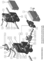
- Patent Illustration Diagram 1 Weft Grip Mechanism, Exploded view (left), Assembled but Cover Removed View (Right)
- the body (1) of weft Grip Mechanism which is mounted securely on a part (numbered 16 and explained further) which is mounted directly on the sley bracket of the weaving machine in such a way that it can be moved sideways at desired position relative to the selvedge of the fabric being woven and can be locked in that place for operation. This is better explained in detail in Description of Patent Illustration 2 below.
- the body (1) has following details built in, hole (1A) is provided in weft grip mechanism body (1) for shaft (8), a Projection (1B) is provided on the body (1) for arresting plate cam (2) and allowing a sideways motion to the plate cam (2), a small space (1C) for slider part (3) is provided on body (1).
- a Suitable number of holes (1D) are provided in the body so that mounting fasteners (12) of the Cover (7) as explained further.
- Plate Cam (2) has following details built in to it.
- a Locking place (2A) is provided for slider part (3)
- a step (2B) is provided for mating with body (1) at (1B)
- two cam slots (2C) are provided for guiding and moving the pins (4B and 5B)
- these pins (4B and 5B) are either integrally built or assembled on weft grip levers (4 and 5) explained further.
- Slider part (3) which gets affixed to the shaft 8 and has following details built on to it.
- 3A is hole through which shaft 8 passes and gets fitted
- 3B is a cross hole through which a part 9 passes through in order to fix the slider 3 to shaft 8.
- the Weft Grip lever Lower (4) which has following details built in to it, A central cylinder portion (4A) which is a pivot for movement of this lever, a cylindrical projection (4C) provided on the motion input lever (4B) to mate with cam slots (2C), and a grip arm (4D) is provided which helps gripping the weft thread in conjunction with Weft Grip Lever upper (5) described further.
- the Weft Grip lever Upper (5) which has following details built in to it, A central cylinder portion (5A) which is a pivot for movement of this lever, a cylindrical projection (5C) re provided on the motion input lever (5B) to mate with cam slots (2C), and a grip arm (5D) is provided which helps gripping the weft thread in conjunction with Weft Grip Lever lower (4) described earlier.
- Bearing cap (6) for Weft Grip Levers (4 and 5) is devised and intended to clamp the cylindrical portion (4A and 5A)
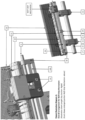
- Patent Illustration Diagram 2
- Sley Shaft (14) provides a mounting for several Sley shaft brackets (15) on which Tee slot part (16) mounted directly on sley brackets (15), the tee slot (16A) of the tee slot part (16) provides the mounting for entire Weft Grip mechanism by means of fasteners (13) in such a manner that it can be affixed to the tee slot in several lateral positions as per fabric width woven on the weaving machine.
- the Extruded Sley profile (17) is also mounted on the sley brackets (15).
- the tee slot part (16) has the small end bearing brackets (18) mounted on both sides of it which provide a sliding support to the shaft (8), another Intermediate support (19) is also provided for shaft (8) to reduce span length and to avoid buckling of shaft (8), this support(19) is also adjustable laterally based on working position of the weft grip mechanism on the tee slot part (16).
- Guide block and rapier tape guide assembly (20) along with Tape Guide plates (21) for rapier and, weaving reed (22) is also mounted on the sley profile (17).
- the weft grip mechanism is so adjusted widthwise in such a manner that the upper and lower weft grip levers are in between two tape guide plates and are not fouling with the plates during opening and closing operation of the same.
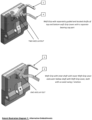
- Patent Illustration Diagram 3
- the small end brackets for shaft (8) are clamped to tee slot part (16) by means of fasteners (16B), these were not visible in any of the earlier views.
- the diagram mainly shows Space for weft carrying media between weft grip lever lower (4) and weft grip lever upper (5) for passing of rapier head and tape through the opened weft grip levers, the view is aligned as if it is seen by the incoming rapier head.
- Patent Illustration Diagram 4
- Shaft (8) carries a Clamping collar Stopper (23A), Clamping Collar (23B) for preloading and return spring (23C) arranged in such a manner that spring (23C) itself executes the return action on shaft (8) to keep it at normal pushed out condition.
- the force of spring (23C) is also the force used for gripping the weft.
- the diagram also elaborates placement of weft grip mechanism in such a manner that the weft grip levers are working between two adjacent tape guides (21).
- Patent Illustration Diagram 5
- This figure shows the driving arrangement of weft grip mechanism.
- Weft Grip Driving Surface Cam assembly is mounted on the machine frame/body and has a setting provision wherein the timing of the weft grip mechanism can be set in a angular advance or retard position relative to the machine.
- the surface cam (24) having a cam plate (24A) and a cylindrical projection (24B) is clamped by a Clamping and setting disk (25) which is diametrically locked and axially free to move on the surface cam cylindrical projection (24B) which is on the other side of the machine frame / body in such a manner that fastening of the screws will sandwich the machine frame between the surface cam body (24A) and clamping Disk (25).
- Cam Cylindrical projection (24B) and Clamping disk (25) is essential because rotating this disk should also apply equal rotation to the cam.
- Swing Lever (26) has a projection (26A) for connection with the connecting rod (31) and an Axial driving shaft (27) passes through the swing lever (26) and is diametrically locked with the swing lever but it is free to slide along its axis and the shaft is spring loaded to remain pressed against the surface cam (24A).
- Axial drive shaft (27) for weft grip mechanism bears a Cam follower mounting clamp (28), provides a seating for return spring (29 ), stopper (30) with a spring mounting disk is fitted on on shaft (27), further connecting rod (31 ) for Swing link (26) gets motion for the swing shaft through connecting rod having big end (31A) and connecting rod small end (31B), the big end of which is mounted on eccentric cam (32) which is in turn mounted on a machine shaft (33) is running at weaving cycle speed.
- WORKING The connecting rod (31) mounted on the eccentric (32) brings an oscillating motion to the swing lever (26) and the same is transferred to the shaft (27) as this shaft is diametrically locked with swing lever (26).
- the cam plate (24A) has a cam projection which is better seen and explained in diagram 6 below, this projection causes the follower (28A) to get pressed backward or forward as it follows the cam surface, pre load of the spring (29) keeps the shaft forcefully pressed on the cam and thus it also drives / presses the shaft (8) depending upon its position on the surface cam.
- the timing, as said earlier is set by means of rotating and clamping the cam along with the setting and clamping disk and locking of fasteners (25B).
- Patent Illustration Diagram 6 is a diagrammatic representation of
- the closed position remains intact during the beat up operation.
- the weft grip mechanism is driven to open position, and as soon as the rapiers exit the shed after transfer of thread, the weft grip is timed to close, coinciding with the gripper opening block timing.
- Patent Illustration Diagram 7
- the weft grip described in above primary embodiment and best mode of this invention is on two axes of upper and lower weft grip levers.
- an alternative embodiment should also be described where in the two axes of the two weft grip upper and lower levers coincide with each other by a hollow shaft in shaft arrangement as shown in diagram 7.
- Another alternative embodiment of this mechanism is in the driving mechanism, wherein the connecting rod connection between the swing lever, connecting rod and the shaft can be replaced by a rack and pinion arrangement where in the shaft shall bear the pinion gear and the connecting rod will be replaced by the rack gear oscillating to and fro path imparting a rotary swing motion to the shaft in order to move the follower bearing over the surface cam in the same fashion.
- Patent Illustration Diagram 1 Weft Grip Mechanism, Exploded view (left), Assembled but Cover Removed View (Right)
- Patent Illustration Diagram 2
- Patent Illustration Diagram 3
- Patent Illustration Diagram 4
- Patent Illustration Diagram 5
- Patent Illustration Diagram 6 Weft Grip and its drive, at open and closed positions
Description
- The following specification particularly describes and ascertains the nature of this inventions and manner in which it is to be performed.
- Present invention relates to textile engineering field and more particularly to the arrangements for tensioning of weft on shuttle less weaving machines. For many decades, catch selvedges or false selvedges are the only resort available for this purpose on shuttle-less weaving machines.
- The invention refers to a Weft Gripping mechanism for use on rapier type shuttle-less weaving machines. There is no such or similar device in existence today and the need for such a mechanism arises from the key points disadvantages of existing systems explained below further.
- Conventionally Catch or False selvedge former, which is a set of selvedge threads which are used to grip the weft yarn. The action is performed just like normal shedding of threads but the only changes which exist are in timing. Catch Selvedge Warp threads are timed to close their shed earlier than body warp and their action too is faster because of short time available to grip the exiting weft insertion media before it relieves the weft from its grip. And because the weft is CAUGHT by the selvedge warp threads, the tension in the weft threads inserted is maintained in such type of set ups. But this mechanism has some serious disadvantages as follows.
-
DE 90 15 788 U1 discloses a device on weaving machines, which serves to actuate working elements arranged on the sley for the weft thread insertion. The actuating device is preferably used on non-shuttle weaving machines whose weft insertion is carried out with bar or band rapiers. This device is intended to clamp the weft between the weft scissors and the supply bobbins in order to avoid the weft thread falling off. - Also, it is known form prior art
US 4 834 147 relating to a weft thread cutting mechanism in a shuttleless loom performs an excess stroke to bring the scissors mechanism, which is combined with a clamping mechanism, as close to the weft thread insertion gripper as possible in order to reduce weft thread waste. For this purpose, the fixed scissors blade is tiltable between a working position and a rest position in a plane extending substantially perpendicularly to the weft thread insertion direction. - Whenever a weft thread is inserted in shed formation, it is always in the form of a single separate thread cut to a certain length. And both the ends of weft, therefore, need to be secured by some means before the insertion mechanism leaves it after which it is cut to length. This securing function is known to be performed by selvedge former which is usually called as FALSE SELVEDGE.
- 1. Conventionally, the timing of false selvedge is normally kept early and some rubbing occurs between the selvedge warp threads and the gripper and it is observed that, out of total machine stoppages as a result of warp thread breakage, the majority of breakages are from this selvedge area because of this rubbing action which cannot be avoided in conventional set ups. With the advent of this path breaking Weft Gripping mechanism, rubbing action is totally eliminated and so will be the breakages due to rubbing. It also improves the gripping force exerted on the weft thread and brings about a better tension control of the weft thread, which is known to be the key element for a better fabric appearance.
- 2. Because the timing of conventional false selvedge is not so precise, excessive wastage of weft yarn occurs as the protruding length of weft thread has to be kept to a higher side. Unlike this, the new weft grip mechanism allows a more precision setting of weft grip, which in turn means exact or optimum weft protruding length, which obviously means lesser wastage of weft yarns. This saving can be a reduction of wastage from 4% to 3% with this device. Although this 1% appears very small, when calculated as a cost of 1% weight of total weft yarn consumed per year, this figures becomes a huge amount of saving. Moreover, 1% reduction in 4% waste is a whopping 25% reduction in waste by its weight. This will surely have a huge commercial significance and impact and a major achievement of this path breaking device.
- 3. The selvedge has to be timed a bit early in order that the insertion mechanism leaves the weft thread after it comes out of the shed and weft must be gripped at this precise moment, the crossing of warp selvedge threads is not one of the precise actions and to find a timing when the warp will grip the weft is too difficult to spot physically on the weaving machine, this makes the timing sequence itself a bit ambiguous and full of compromises. The new Weft Grip Mechanism will eliminate this ambiguity of timing altogether.
- 4. As mentioned above, the rubbing action of selvedge warp and weft insertion gripper makes the whole idea of this type of gripping vulnerable by dangers of thread breakage and machine stoppages point of view. Any saving in this breakage instances means improvement in the machine efficiency and saving losses arising out of down time in the event of thread breakages, this also has a quality significance as each start and stop on a weaving machine can result in fabric defects known as start/stop marks. The new Weft Grip Mechanism will thus improve efficiency as well as the quality of cloth produced on the machine.
-
- 1. Where in the main objective of the invention is to grip the weft thread by purely mechanical means, and unlike conventional false selvedges, before it is cut to length on a shuttle less weaving machine.
- 2. Wherein the supplementary objective of the invention is to art a weft gripping mechanism, the action timing of which will be easy and precise to set and thus exercise control over the weft yarn wastage by establishing a precise control over the protruding length of weft beyond the grip.
- 3. Wherein the another additional objective of the invention is to art a weft gripping mechanism wherein the force exerted on weft thread, upon grip, can be precisely set according to the weft yarn variety, so as to achieve a better fabric appearance.
- 4. Wherein another additional objective of the invention is that the weft grip mechanism is an additional device on the weaving machine, thus it should be very compact and should not hinder with the existing mechanisms on the weaving machine.
- The invention will now be described with the help of a drawing accompanying this specification wherein salient features have been shown by suitable numerals and referred to appropriately in the following description.
- The body (1) of weft Grip Mechanism which is mounted securely on a part (numbered 16 and explained further) which is mounted directly on the sley bracket of the weaving machine in such a way that it can be moved sideways at desired position relative to the selvedge of the fabric being woven and can be locked in that place for operation. This is better explained in detail in Description of
Patent Illustration 2 below. The body (1) has following details built in, hole (1A) is provided in weft grip mechanism body (1) for shaft (8), a Projection (1B) is provided on the body (1) for arresting plate cam (2) and allowing a sideways motion to the plate cam (2), a small space (1C) for slider part (3) is provided on body (1). A Suitable number of holes (1D) are provided in the body so that mounting fasteners (12) of the Cover (7) as explained further. - Further, Plate Cam (2) has following details built in to it. A Locking place (2A) is provided for slider part (3), a step (2B) is provided for mating with body (1) at (1B), two cam slots (2C) are provided for guiding and moving the pins (4B and 5B), these pins (4B and 5B) are either integrally built or assembled on weft grip levers (4 and 5) explained further.
- Slider part (3) which gets affixed to the
shaft 8 and has following details built on to it. 3A is hole through whichshaft 8 passes and gets fitted, 3B is a cross hole through which apart 9 passes through in order to fix theslider 3 toshaft 8. - The Weft Grip lever Lower (4) which has following details built in to it, A central cylinder portion (4A) which is a pivot for movement of this lever, a cylindrical projection (4C) provided on the motion input lever (4B) to mate with cam slots (2C), and a grip arm (4D) is provided which helps gripping the weft thread in conjunction with Weft Grip Lever upper (5) described further.
- The Weft Grip lever Upper (5), which has following details built in to it, A central cylinder portion (5A) which is a pivot for movement of this lever, a cylindrical projection (5C) re provided on the motion input lever (5B) to mate with cam slots (2C), and a grip arm (5D) is provided which helps gripping the weft thread in conjunction with Weft Grip Lever lower (4) described earlier.
- Bearing cap (6) for Weft Grip Levers (4 and 5) is devised and intended to clamp the cylindrical portion (4A and 5A)
- Cover (7) of the weft grip mechanism is devised to enclose all moving parts inside it, together with the projection (1B) described above it provides a sliding guide to the cam(2)
- Sliding shaft (8) is intended to impart motion to weft Grip actuation through slider part (3) described earlier
- Slider Part (3) is affixed to the shaft (8) by a brass / copper sleeve (9)
- A fastener (10) is provided for clamping sleeve (9), and fasteners (11) for bearing cap (6), fasteners (12) are provided for fastening the cover (7) on to Body (1), Fasteners (13) are for fixing the weft grip mechanism on the tee slot part at desired lateral position depending on fabric width.
WORKING : The body (1) of the weft grip mechanism is affixed by fasteners (13), shaft (8) passes through the hole in body (1) at (1A), in such a way that slider part (3) is engaged with the shaft (8), at hole in to slider (3) at (3A), and it remains in to a small recess (1C) in body (1). Slider (3) is affixed to shaft (8) by means of clamping sleeve (9) and a fastener (10). This way the slider part (9) moves in unison with shaft (8) but within the recess (1C). Weft Grip lower (4) and weft Gripp upper (5) are mounted on to body (1) as shown in figure by means of cap (6) and fasteners (11) in such a way that they can freely swing around their axes at (4A and 5A). Now the plate cam (2) sits on Body (1) in such a way that face (2B) is butted with lower surface of Projection (1B) and Pins (4B and 5B) engage with slots (2C) in the plate cam (2), at the same time plate cam is also mounted in such a way that the notch (2A) engages with the slider part (9) and motion of the shaft(8) is thus transferred to the plate cam (2). The to and fro motion of shaft (8), thus gets transferred to slider part (9), then to Plate cam (2) and then to the Weft Grip lower and upper (4 and 5) through mechanical mate between slots (2C) and pins (4B and 5B). The weft grip can thus open and close based on position of the shaft(8) in a reliable manner. - This diagram shows an illustration of small section of sley on which a weft grip mechanism is mounted and it is shown as a small section for the sake of description simplicity, however sley will be much longer than what is shown and plurality of sley brackets are present on the machine. Sley Shaft (14) provides a mounting for several Sley shaft brackets (15) on which Tee slot part (16) mounted directly on sley brackets (15), the tee slot (16A) of the tee slot part (16) provides the mounting for entire Weft Grip mechanism by means of fasteners (13) in such a manner that it can be affixed to the tee slot in several lateral positions as per fabric width woven on the weaving machine. The Extruded Sley profile (17) is also mounted on the sley brackets (15). The tee slot part (16) has the small end bearing brackets (18) mounted on both sides of it which provide a sliding support to the shaft (8), another Intermediate support (19) is also provided for shaft (8) to reduce span length and to avoid buckling of shaft (8), this support(19) is also adjustable laterally based on working position of the weft grip mechanism on the tee slot part (16). Guide block and rapier tape guide assembly (20) along with Tape Guide plates (21) for rapier and, weaving reed (22) is also mounted on the sley profile (17). The weft grip mechanism is so adjusted widthwise in such a manner that the upper and lower weft grip levers are in between two tape guide plates and are not fouling with the plates during opening and closing operation of the same.
- The small end brackets for shaft (8) are clamped to tee slot part (16) by means of fasteners (16B), these were not visible in any of the earlier views. The diagram mainly shows Space for weft carrying media between weft grip lever lower (4) and weft grip lever upper (5) for passing of rapier head and tape through the opened weft grip levers, the view is aligned as if it is seen by the incoming rapier head.
- The diagram shows overall view of the weft grip assembly as seen from the top of the weaving machine. the details of the two rectangles are shown in enlarged view for better understanding of the same at the bottom indicated by respective enlargement arrows. Shaft (8) carries a Clamping collar Stopper (23A), Clamping Collar (23B) for preloading and return spring (23C) arranged in such a manner that spring (23C) itself executes the return action on shaft (8) to keep it at normal pushed out condition. The force of spring (23C) is also the force used for gripping the weft. Stronger the spring better will be the gripping force on the weft yarn and vice versa, and this has to be set according to the type of yarn used, lighter spring for delicate yarns and stronger spring for coarser weft yarns. The diagram also elaborates placement of weft grip mechanism in such a manner that the weft grip levers are working between two adjacent tape guides (21).
- This figure shows the driving arrangement of weft grip mechanism. Weft Grip Driving Surface Cam assembly is mounted on the machine frame/body and has a setting provision wherein the timing of the weft grip mechanism can be set in a angular advance or retard position relative to the machine. The surface cam (24) having a cam plate (24A) and a cylindrical projection (24B) is clamped by a Clamping and setting disk (25) which is diametrically locked and axially free to move on the surface cam cylindrical projection (24B) which is on the other side of the machine frame / body in such a manner that fastening of the screws will sandwich the machine frame between the surface cam body (24A) and clamping Disk (25). The diametrical lock between Cam Cylindrical projection (24B) and Clamping disk (25) is essential because rotating this disk should also apply equal rotation to the cam. There are several radial holes (25A) on periphery of clamping disk for facilitating setting movement. Swing Lever (26) has a projection (26A) for connection with the connecting rod (31) and an Axial driving shaft (27) passes through the swing lever (26) and is diametrically locked with the swing lever but it is free to slide along its axis and the shaft is spring loaded to remain pressed against the surface cam (24A). Axial drive shaft (27) for weft grip mechanism bears a Cam follower mounting clamp (28), provides a seating for return spring (29 ), stopper (30) with a spring mounting disk is fitted on on shaft (27), further connecting rod (31 ) for Swing link (26) gets motion for the swing shaft through connecting rod having big end (31A) and connecting rod small end (31B), the big end of which is mounted on eccentric cam (32) which is in turn mounted on a machine shaft (33) is running at weaving cycle speed.
WORKING : The connecting rod (31) mounted on the eccentric (32) brings an oscillating motion to the swing lever (26) and the same is transferred to the shaft (27) as this shaft is diametrically locked with swing lever (26). The cam plate (24A) has a cam projection which is better seen and explained in diagram 6 below, this projection causes the follower (28A) to get pressed backward or forward as it follows the cam surface, pre load of the spring (29) keeps the shaft forcefully pressed on the cam and thus it also drives / presses the shaft (8) depending upon its position on the surface cam. The timing, as said earlier is set by means of rotating and clamping the cam along with the setting and clamping disk and locking of fasteners (25B). - Refer to diagram A) Weft Grip of Closed (Gripped) position and/or just before opening position, unless opened by the driving mechanism, the weft grip remains in closed or gripped position, at this position the lever (26A) remains rotated at lower most position as shown by rotary arrow around
label 26A, thus follower (28A) remains riding on the cam projection and pressed back towards the activation spring (29), shaft (27) remains retracted behind and thus shaft (8) is at free position, the weft Grip is at closed position. - Refer to diagram B) Weft Grip of Opened position or during weft insertion phase, this is activated position of the mechanism and activation means opening of weft grip, at this position the lever (26A) remains rotated to uppermost most position as shown by rotary arrow around
label 26A, thus follower (28A) is released from the cam projection and gets pressed forward by the activation spring (29), shaft (27) comes out as a result and thus shaft (8) is also pressed towards the open position, the weft Grip is also at position, allowing the passage of the weft gripper through. - The closed position remains intact during the beat up operation. As soon as the sley comes back to backward most position or the position where rapier heads move inside the shed formation, but before the rapiers move in, the weft grip mechanism is driven to open position, and as soon as the rapiers exit the shed after transfer of thread, the weft grip is timed to close, coinciding with the gripper opening block timing.
- The alternative embodiments. The weft grip described in above primary embodiment and best mode of this invention, is on two axes of upper and lower weft grip levers. However an alternative embodiment should also be described where in the two axes of the two weft grip upper and lower levers coincide with each other by a hollow shaft in shaft arrangement as shown in diagram 7.
- Another alternative embodiment of this mechanism is in the driving mechanism, wherein the connecting rod connection between the swing lever, connecting rod and the shaft can be replaced by a rack and pinion arrangement where in the shaft shall bear the pinion gear and the connecting rod will be replaced by the rack gear oscillating to and fro path imparting a rotary swing motion to the shaft in order to move the follower bearing over the surface cam in the same fashion.
- From the descriptions of the diagrams above, it is clearly established that all main as well as secondary objectives of the invention are clearly achieved.
- The nomenclature relates to 7 Patent Illustration diagrams enclosed with this.
-
- 1 is body of weft Grip Mechanism,
- 1A is hole for
shaft 8, - 1B is Projection for arresting plate cam,
- 1C is space for
slider part 3 - 1D are mounting holes for
cover 7
- 1A is hole for
- 2 is Plate Cam,
- 2A is Locking place for
slider part 3, - 2B is step for mating with
body 1 at 1B, - 2C is cam slots for guiding
pins
- 2A is Locking place for
- 3 is slider part
- 3A is hole for
shaft 8 - 3B is cross hole for clamping
part 9
- 3A is hole for
- 4 is Weft Grip lever lower,
- 4A is central cylinder portion or pivot,
- 4B is motion input lever
- 4C is cylindrical projections to mate with
cam slots 2C - 4D is grip arm
- 5 is Weft Grip lever upper,
- 5A is central cylinder portion or pivot,
- 5B is motion input lever
- 5C is cylindrical projection to mate with
cam slots 2C - 5D is grip arm
- 6 is Bearing cap for
Weft Grip Levers - 7 is cover of weft grip mechanism
- 8 is sliding shaft of weft Grip actuation
- 9 is brass / copper sleeve for clamping
part 3 toshaft 8 - 10 is fastener for
sleeve 9 - 11 are fasteners for bearing
cap 6 - 12 are fasteners for
cover 7 - (Repeating Numerals from 1 to 12 should please be referred to description on
Patent Illustration 1 above) - 13 is fastener for weft grip on tee slot part
- 14 is sley shaft
- 15 are sley shaft brackets
- 16 is tee slot part mounted on
sley shaft brackets 15
16A is tee slot in which the Weft Grip mechanism is mounted - 17 is sley extruded profile
- 18 are end bearings mounted on both sides
Tee Slot part 16 - 19 is intermediate support for
shaft 8 - 20 is guide block and rapier tape guide assembly
- 21 is guide plates for rapier of
assembly 20 - 22 is weaving reed
-
-
(Repeating Numerals from 1 to 12 should please be referred to description on
Patent Illustrations 1 above) -
(Repeating Numerals from 13 to 22 should please be referred to description on
Patent Illustrations 2 above) -
-
(Repeating Numerals from 1 to 12 should please be referred to description on
Patent Illustrations 1 above) -
(Repeating Numerals from 13 to 22 should please be referred to description on
Patent Illustrations 2 above) - 23A is a Clamping collar Stopper for
shaft 8 for - 23B is a Clamping Collar for
spring 23C preloading - 23C is a return spring for
shaft 8 -
-
(Repeating Numerals from 1 to 12 should please be referred to description on
Patent Illustrations 1 above) -
(Repeating Numerals from 13 to 22 should please be referred to description on
Patent Illustrations 2 above) -
(Repeating Numerals from 23 should please be referred to description on
Patent Illustrations 4 above) - 24 is surface cam for weft grip drive
- 24A is surface cam plate
- 24B is cylindrical projection of the cam
- 25 is clamping ana setting disk
- 25 A are holes on periphery of clamping disk for setting movement
- 25B are fasteners for locking surface cam and clamping disk through frame
- 26 is Swing Lever for driving
shaft 27
26A is swing lever projection - 27 is Axial drive shaft for weft grip mechanism
- 28 is Cam follower mounting clamp
- 29 is return spring for
shaft 27 - 30 is stopper and spring mounting disk on
shaft 27 - 31 is connecting rod for
Swing link 26- 31A is connecting rod big end
- 31B is connecting rod small end
- 32 is eccentric cam
- 33 is machine shaft running at weaving speed
-
-
(Repeating Numerals from 1 to 12 should please be referred to description on
Patent Illustrations 1 above) -
(Repeating Numerals from 13 to 22 should please be referred to description on
Patent Illustrations 2 above) -
(Repeating Numerals from 23 should please be referred to description on
Patent Illustrations 4 above) -
(Repeating Numerals from 24 to 33 should please be referred to description on
Patent Illustrations 5 above) - 28A cam follower
-
-
(Repeating Numerals from 1 to 12 should please be referred to description on
Patent Illustrations 1 above) -
(Repeating Numerals from 13 to 22 should please be referred to description on
Patent Illustrations 2 above) -
(Repeating Numerals from 23 should please be referred to description on
Patent Illustrations 4 above) -
(Repeating Numerals from 24 to 33 should please be referred to description on
Patent Illustrations 5 above)
Claims (14)
- A shuttleless weaving machine comprising a body (1) and a weft gripping mechanism for gripping a weft thread by mechanical means before it is cut to length for mounting on an oscillating sley of the shuttleless weaving machine, wherein the weft gripping mechanism comprises a driving mechanism that is configured to be mounted stationary on the weaving machine body;
characterized in that:the weft gripping mechanism comprises a pair of weft gripping levers (4, 5) on exit side of weft insertion to control weft tension during beat up before it is cut to length is placed on the oscillating sley by means of a tee slot part (16) of the oscillating sley, the tee slot part (16) comprising a tee slot (16A), having a length that facilitates lateral adjustments of the weft grip mechanism;the driving mechanism opens or closes the weft gripper only when the oscillating sley is at the back center position or weft insertion position; andthe weft gripping mechanism is so sized that it does not create any hindrance to other weaving machine parts;wherein the a body (1) of the weft gripping mechanism comprises fasteners (13) for fixation on the oscillating sley by means of the tee slot part (16), a shaft (8) passes through an appropriately sized hole (1A) in body (1) in such a way that a slider part (3) is engaged with the shaft (8), at hole (3A) in to slider part (3), and it remains in to a recess (1C) at a near central position of the body (1), further this slider part (3) is affixed to shaft (8) by means of clamping sleeve (9) and at least one fastener (10), in such a way that the slider part (3) moves in unison with shaft (8) but within the recess (IC), a lower weft gripping lever (4) and an upper weft gripping lever (5) are mounted on to body (1) by means of a bearing cap (6) and fasteners (11) in such a way that they can freely swing at an angle between 15 to 45 degrees around their axes and pivot supports (4A and 5A), a plate cam (2) sits on body (1) in such a way that a face (2B) is butted with lower surface of projection (1B) and pins (4B and 5B) engage with slots (2C) in the plate cam (2), the plate cam is also mounted in such a way that a notch (2A) engages with the slider part (3) and motion of the shaft (8) is thus transferred to the plate cam (2), the to and fro motion of shaft (8) thus gets transferred to slider part (3), then to plate cam (2) and then to the weft grippers lower and upper levers (4 and 5) through mechanical mate between slots (2C) and pins (4B and 5B), the weft gripper can thus open and close based on the position of the shaft (8) in a reliable manner;wherein the weft gripping mechanism is configured to be mounted on the oscillating sley, the driving system for the weft gripping mechanism is configured to be mounted on the stationary weaving machine body and consists of a connecting rod (31) mounted on an eccentric cam (32), which brings an oscillating motion to a swing lever (26) which is transferred to an axial driving shaft (27), this axial driving shaft (27) is diametrically locked with swing lever (26) by means of a key way connection or splined connection or triangular or polygonal shaft connection, swing lever (26) is guided properly in the machine body and is free to rotate or oscillate, a cam plate (24A) has a cam projection which causes a follower (28A) to get pressed backward or forward as it follows a surface cam (24), pre load of an activation spring (29) keeps the shaft forcefully pressed on the plate cam (2), thereby driving or pressing the shaft (8) depending upon its position on the surface cam (24),wherein the weft gripping mechanism comprises a face cam follower and shaft driven by a rack and pinion mechanism, wherein the weft gripping mechanism is precisely timed by running the machine in micro slow motion or by setting the timing;wherein the swing lever (26) has a projection (26A) for connection with the connecting rod (31) and the axial driving shaft (27) passes through the swing lever (26) and the axial driving shaft (27) is diametrically locked with the swing lever (26) but the axial driving shaft (27) is free to slide along its axis and the shaft is spring loaded to remain pressed against the surface cam (24A), wherein the axial driving shaft (27) for weft gripping mechanism bears a cam follower mounting clamp (28) and provides a seating for the activation spring (29), wherein a stopper (30) with a spring mounting disk is fitted on the axial driving shaft (27), and wherein the connecting rod (31) for the swing lever (26) gets motion for the axial driving shaft (27) through connecting rod (31) having a big end (31A) and a small end (31B), wherein the big end (31A) of the connecting rod (31) is mounted on the eccentric cam (32) which is in turn configured to be mounted on a machine shaft (33) which runs at weaving cycle speed;wherein the weft gripping mechanism has a thickness in a direction parallel to the pivot supports (4A, 5A), and wherein the thickness of the weft gripping mechanism is smaller than the length of the connecting rod (31). - The weaving machine of claim 1, wherein, in order to execute the gripping of weft thread, the weft gripping levers carry a soft lining of polymer material or rubber so that yarn can be gripped by friction; or metallic gripping levers with a firm gripping surface formed either by machining or grinding of the gripping surface.
- The weaving machine of claim 1, wherein the weft gripping levers comprise an arrangement of the levers with separately guided and located shafts of top and bottom weft gripping levers with a separate bearing cap (6).
- The weaving machine of claim 1, wherein the weft gripping levers comprise two shafts coaxially running inside one another on one axis of operation.
- The weaving machine of any one of claims 1-4, wherein the timing of the weft grippers is set by means of rotating and re-clamping the plate cam (2) along with a clamping and setting disk (25) and locking of fasteners (25B).
- The weaving machine of claim 1, wherein a weft gripper driving surface cam assembly has a setting provision wherein the timing of the weft gripping mechanism can be set in an angular advance or retard position relative to the machine.
- The weaving machine of any one of claims 1-6, wherein the surface cam (24) having the cam plate (24A) and a cam cylindrical projection (24B) is clamped by the clamping and setting disk (25) which is diametrically locked and axially free to move on the surface of the cam cylindrical projection (24B) which is on the other side of the machine frame or body in such a manner that fastening of the screws (25B) will sandwich the machine frame between the surface cam body (24A) and clamping disk (25).
- The weaving machine of claim 7, wherein the diametrical lock between cam cylindrical projection (24B) and clamping disk (25) is achieved by means of a key way connection or splined connection or triangular or polygonal shaft connection, and rotating the clamping disk (25) applies an equal rotation to the plate cam (2), and further, a plurality of radial holes (25A) on periphery of clamping disk facilitate the setting movement.
- The weaving machine of any one of claims 1-8, wherein when the weft gripper remains in closed or gripped position, at this position the swing lever (26) remains rotated at lower most position, follower (28A) remains riding on the cam projection and pressed back towards the activation spring (29), axial driving shaft (27) remains retracted behind, and shaft (8) is at free position.
- The weaving machine of any one of claims 1-9, wherein when the weft gripper is in an opened position or during weft insertion phase, the swing lever (26) remains rotated to upper most position, follower (28A) is released from the cam projection (24B) and gets pressed forward by the activation spring (29), axial driving shaft (27) comes out and shaft (8) is also pressed towards the open position, thereby allowing the passage of the weft gripping mechanism between the open levers (4) and (5).
- The weaving machine of any one of claims 1-10, wherein the closed position of the weft gripper remains intact during the beat up operation, and wherein as soon as the oscillating sley comes back to backward most position or the position where rapier heads move inside the shed formation, but before the rapiers move in, the weft gripping mechanism is driven to open position, and further as soon as the rapiers exit the shed after transfer of thread, the weft gripper is timed to close, coinciding with the gripper opening block timing.
- The weaving machine of any one of claims 1-11, wherein the shaft (8) carries a clamping collar stopper (23A), clamping collar (23B) for preloading and a return spring (23C) arranged in such a manner that spring (23C) itself executes the return action on shaft (8) to keep it at normal pushed out condition, the force of return spring (23C) is also the force used for gripping the weft, and the weft gripping mechanism is placed in such a manner that the weft gripping levers are working between two adjacent tape guides (21) which are complimented by the weft gripping levers (4 and 5).
- The weaving machine of claim 12, wherein the force of return spring (23C) is also the force used for gripping the weft and wherein the spring is set according to the type of yarn used, lighter spring for delicate yarns and stronger spring for coarser yarns.
- The weaving machine of any one of claims 1-13, wherein a cover (7) of the weft gripping mechanism covers the entire mechanism from dust and dirt in weaving rooms and also provides a geometrical arrest to the slider plate cam (2) wherein the cam has only freedom of movement along the slider path and nowhere else, and also contains grease for lubrication of the entire mechanism, and wherein at least one fastener (12) is used to clamp the cover on to the body (1) of the weft gripping mechanism.
Applications Claiming Priority (2)
| Application Number | Priority Date | Filing Date | Title |
|---|---|---|---|
| IN201621031285 | 2016-09-14 | ||
| PCT/IB2017/050924 WO2018051193A1 (en) | 2016-09-14 | 2017-02-17 | Weft gripping mechanism for shuttleles weaving machines |
Publications (4)
| Publication Number | Publication Date |
|---|---|
| EP3512991A1 EP3512991A1 (en) | 2019-07-24 |
| EP3512991A4 EP3512991A4 (en) | 2020-05-06 |
| EP3512991B1 true EP3512991B1 (en) | 2024-01-17 |
| EP3512991C0 EP3512991C0 (en) | 2024-01-17 |
Family
ID=61618658
Family Applications (1)
| Application Number | Title | Priority Date | Filing Date |
|---|---|---|---|
| EP17850359.5A Active EP3512991B1 (en) | 2016-09-14 | 2017-02-17 | Weft gripping mechanism for shuttleles weaving machines |
Country Status (3)
| Country | Link |
|---|---|
| EP (1) | EP3512991B1 (en) |
| CN (1) | CN109844197B (en) |
| WO (1) | WO2018051193A1 (en) |
Families Citing this family (1)
| Publication number | Priority date | Publication date | Assignee | Title |
|---|---|---|---|---|
| CN117188021B (en) * | 2023-11-07 | 2024-03-22 | 江苏维凯科技股份有限公司 | Aramid fiber base cloth double-warp double-weft weaving device for radome |
Family Cites Families (14)
| Publication number | Priority date | Publication date | Assignee | Title |
|---|---|---|---|---|
| GB1068316A (en) * | 1963-06-18 | 1967-05-10 | Jose Llado Llado | Improved device for operating loom shears |
| ES343667A1 (en) * | 1967-07-13 | 1968-09-01 | Balaguer Golobart | Device for cutting and aspiration of the lateral suppliers of the wire threads in fixed-line telescopes. (Machine-translation by Google Translate, not legally binding) |
| DE3703638C1 (en) * | 1987-02-06 | 1988-05-19 | Dornier Gmbh Lindauer | Weft cutter |
| IT1230000B (en) * | 1989-04-21 | 1991-09-20 | Somet Soc Mec Tessile | AXIAL MOVABLE SLOT-HOLDER PLIER FOR WEAVING FRAMES WITHOUT SHUTTLE. |
| DE9015788U1 (en) * | 1990-11-19 | 1991-04-25 | Ingenieurbuero Und Rationalisierung Gmbh Ibr-Plauen, O-9900 Plauen, De | |
| BE1008211A5 (en) * | 1993-07-29 | 1996-02-13 | Wiele Michel Van De Nv | APPARATUS FOR POSITIONING A WIDE SCISSOR ON A WEAVING MACHINE. |
| DE4415862C1 (en) * | 1994-05-05 | 1995-04-27 | Dornier Gmbh Lindauer | Device for the controlled actuation of a thread clamp of a gripper in weaving machines |
| JPH08260291A (en) * | 1995-03-29 | 1996-10-08 | Nissan Tecsys Kk | Weft yarn retaining device for fluid jet loom |
| JP3366564B2 (en) * | 1997-12-26 | 2003-01-14 | ダイヤテックス株式会社 | Weft holding device for loom |
| IT1304699B1 (en) * | 1998-12-23 | 2001-03-28 | Somet Soc Mec Tessile | LEVER TO OPERATE THE WEFT STAPLING DEVICES IN A PAIR OF CARRIER AND TRACTOR PLIERS FOR WEAVING FRAMES |
| JP2002302847A (en) * | 2001-04-03 | 2002-10-18 | Tsudakoma Corp | Weft-holding device |
| WO2004035892A1 (en) * | 2002-10-15 | 2004-04-29 | Tsudakoma Kogyo Kabushiki Kaisha | Weft holding device |
| CN202247159U (en) * | 2011-07-25 | 2012-05-30 | 青岛铠硕纺机有限公司 | Weft yarn clamp holder |
| CN204530100U (en) * | 2015-02-13 | 2015-08-05 | 乐清市宏意纺机配件厂 | A kind of adjustable twin coil yarn gripper |
-
2017
- 2017-02-17 EP EP17850359.5A patent/EP3512991B1/en active Active
- 2017-02-17 CN CN201780056477.3A patent/CN109844197B/en active Active
- 2017-02-17 WO PCT/IB2017/050924 patent/WO2018051193A1/en unknown
Also Published As
| Publication number | Publication date |
|---|---|
| CN109844197B (en) | 2021-04-20 |
| EP3512991A1 (en) | 2019-07-24 |
| WO2018051193A1 (en) | 2018-03-22 |
| EP3512991A4 (en) | 2020-05-06 |
| CN109844197A (en) | 2019-06-04 |
| EP3512991C0 (en) | 2024-01-17 |
Similar Documents
| Publication | Publication Date | Title |
|---|---|---|
| CN105765122B (en) | For the device of cutting weft yarn in loom weaving process and the loom with this device | |
| EP3512991B1 (en) | Weft gripping mechanism for shuttleles weaving machines | |
| US3861427A (en) | Carriers for weft insertion by the rapier principle with positive gripping for shuttleless looms | |
| US3851679A (en) | Device for retaining the end of a weft thread in looms | |
| RU2501893C2 (en) | Head of rapier for weaving machine | |
| JPH11513445A (en) | Loom with pneumatic weft insertion mechanism | |
| US3929169A (en) | Thread brake | |
| US4949762A (en) | Weft gripper for shuttleless loom | |
| US6725886B2 (en) | Device for presenting weft yarns on a rapier weaving machine | |
| US3111966A (en) | Method and apparatus for simultaneously weaving lengths of fabric | |
| CA1052236A (en) | Loom for weaving | |
| KR100434220B1 (en) | Weaving loom with pneumatic weft thread insertion | |
| KR102554487B1 (en) | Gripper assembly for inserting weft threads on a bookless loom | |
| US3875974A (en) | Device for controlling gripper shuttles in looms | |
| EP3478882B1 (en) | Device for clamping weft threads | |
| US3851677A (en) | Shuttle loom | |
| JPH0674538B2 (en) | Weft cutting device for shuttleless loom | |
| JPH09137338A (en) | Weft-insertion method for rapier loom | |
| US3376900A (en) | Looms operating with multi-color stationary weft supplies | |
| US3587662A (en) | Weft distributor for shuttleless loom | |
| US3424207A (en) | Shuttleless wire loom | |
| EP2184389B1 (en) | Weft insertion method and weft insertion device of rapier loom | |
| US2759496A (en) | Gripper shuttle having a thread clamp | |
| JPH0578952A (en) | Fiber-feeding cutter for repia loom | |
| US822169A (en) | Thread-cutting device |
Legal Events
| Date | Code | Title | Description |
|---|---|---|---|
| STAA | Information on the status of an ep patent application or granted ep patent |
Free format text: STATUS: THE INTERNATIONAL PUBLICATION HAS BEEN MADE |
|
| PUAI | Public reference made under article 153(3) epc to a published international application that has entered the european phase |
Free format text: ORIGINAL CODE: 0009012 |
|
| STAA | Information on the status of an ep patent application or granted ep patent |
Free format text: STATUS: REQUEST FOR EXAMINATION WAS MADE |
|
| 17P | Request for examination filed |
Effective date: 20190410 |
|
| AK | Designated contracting states |
Kind code of ref document: A1 Designated state(s): AL AT BE BG CH CY CZ DE DK EE ES FI FR GB GR HR HU IE IS IT LI LT LU LV MC MK MT NL NO PL PT RO RS SE SI SK SM TR |
|
| AX | Request for extension of the european patent |
Extension state: BA ME |
|
| DAV | Request for validation of the european patent (deleted) | ||
| DAX | Request for extension of the european patent (deleted) | ||
| A4 | Supplementary search report drawn up and despatched |
Effective date: 20200402 |
|
| RIC1 | Information provided on ipc code assigned before grant |
Ipc: D03D 47/23 20060101AFI20200328BHEP Ipc: D03D 47/12 20060101ALI20200328BHEP |
|
| STAA | Information on the status of an ep patent application or granted ep patent |
Free format text: STATUS: EXAMINATION IS IN PROGRESS |
|
| STAA | Information on the status of an ep patent application or granted ep patent |
Free format text: STATUS: EXAMINATION IS IN PROGRESS |
|
| 17Q | First examination report despatched |
Effective date: 20210120 |
|
| STAA | Information on the status of an ep patent application or granted ep patent |
Free format text: STATUS: EXAMINATION IS IN PROGRESS |
|
| GRAP | Despatch of communication of intention to grant a patent |
Free format text: ORIGINAL CODE: EPIDOSNIGR1 |
|
| STAA | Information on the status of an ep patent application or granted ep patent |
Free format text: STATUS: GRANT OF PATENT IS INTENDED |
|
| INTG | Intention to grant announced |
Effective date: 20230922 |
|
| GRAS | Grant fee paid |
Free format text: ORIGINAL CODE: EPIDOSNIGR3 |
|
| GRAA | (expected) grant |
Free format text: ORIGINAL CODE: 0009210 |
|
| STAA | Information on the status of an ep patent application or granted ep patent |
Free format text: STATUS: THE PATENT HAS BEEN GRANTED |
|
| AK | Designated contracting states |
Kind code of ref document: B1 Designated state(s): AL AT BE BG CH CY CZ DE DK EE ES FI FR GB GR HR HU IE IS IT LI LT LU LV MC MK MT NL NO PL PT RO RS SE SI SK SM TR |
|
| REG | Reference to a national code |
Ref country code: GB Ref legal event code: FG4D |
|
| REG | Reference to a national code |
Ref country code: CH Ref legal event code: EP |
|
| REG | Reference to a national code |
Ref country code: DE Ref legal event code: R096 Ref document number: 602017078573 Country of ref document: DE |
|
| REG | Reference to a national code |
Ref country code: IE Ref legal event code: FG4D |
|
| U01 | Request for unitary effect filed |
Effective date: 20240215 |
|
| U07 | Unitary effect registered |
Designated state(s): AT BE BG DE DK EE FI FR IT LT LU LV MT NL PT SE SI Effective date: 20240223 |
|
| U20 | Renewal fee paid [unitary effect] |
Year of fee payment: 8 Effective date: 20240220 |