EP3512933B1 - Vorrichtung und verfahren zur echtzeit-erkennung von pathogenen in der luft - Google Patents
Vorrichtung und verfahren zur echtzeit-erkennung von pathogenen in der luft Download PDFInfo
- Publication number
- EP3512933B1 EP3512933B1 EP16921915.1A EP16921915A EP3512933B1 EP 3512933 B1 EP3512933 B1 EP 3512933B1 EP 16921915 A EP16921915 A EP 16921915A EP 3512933 B1 EP3512933 B1 EP 3512933B1
- Authority
- EP
- European Patent Office
- Prior art keywords
- aeropathogen
- detection
- aeropathogens
- detection chamber
- air
- Prior art date
- Legal status (The legal status is an assumption and is not a legal conclusion. Google has not performed a legal analysis and makes no representation as to the accuracy of the status listed.)
- Active
Links
Images


Classifications
-
- G—PHYSICS
- G01—MEASURING; TESTING
- G01N—INVESTIGATING OR ANALYSING MATERIALS BY DETERMINING THEIR CHEMICAL OR PHYSICAL PROPERTIES
- G01N15/00—Investigating characteristics of particles; Investigating permeability, pore-volume or surface-area of porous materials
- G01N15/06—Investigating concentration of particle suspensions
- G01N15/0656—Investigating concentration of particle suspensions using electric, e.g. electrostatic methods or magnetic methods
-
- B—PERFORMING OPERATIONS; TRANSPORTING
- B01—PHYSICAL OR CHEMICAL PROCESSES OR APPARATUS IN GENERAL
- B01D—SEPARATION
- B01D11/00—Solvent extraction
- B01D11/04—Solvent extraction of solutions which are liquid
- B01D11/0496—Solvent extraction of solutions which are liquid by extraction in microfluidic devices
-
- B—PERFORMING OPERATIONS; TRANSPORTING
- B01—PHYSICAL OR CHEMICAL PROCESSES OR APPARATUS IN GENERAL
- B01L—CHEMICAL OR PHYSICAL LABORATORY APPARATUS FOR GENERAL USE
- B01L3/00—Containers or dishes for laboratory use, e.g. laboratory glassware; Droppers
- B01L3/50—Containers for the purpose of retaining a material to be analysed, e.g. test tubes
- B01L3/502—Containers for the purpose of retaining a material to be analysed, e.g. test tubes with fluid transport, e.g. in multi-compartment structures
- B01L3/5027—Containers for the purpose of retaining a material to be analysed, e.g. test tubes with fluid transport, e.g. in multi-compartment structures by integrated microfluidic structures, i.e. dimensions of channels and chambers are such that surface tension forces are important, e.g. lab-on-a-chip
- B01L3/502715—Containers for the purpose of retaining a material to be analysed, e.g. test tubes with fluid transport, e.g. in multi-compartment structures by integrated microfluidic structures, i.e. dimensions of channels and chambers are such that surface tension forces are important, e.g. lab-on-a-chip characterised by interfacing components, e.g. fluidic, electrical, optical or mechanical interfaces
-
- B—PERFORMING OPERATIONS; TRANSPORTING
- B01—PHYSICAL OR CHEMICAL PROCESSES OR APPARATUS IN GENERAL
- B01L—CHEMICAL OR PHYSICAL LABORATORY APPARATUS FOR GENERAL USE
- B01L3/00—Containers or dishes for laboratory use, e.g. laboratory glassware; Droppers
- B01L3/50—Containers for the purpose of retaining a material to be analysed, e.g. test tubes
- B01L3/502—Containers for the purpose of retaining a material to be analysed, e.g. test tubes with fluid transport, e.g. in multi-compartment structures
- B01L3/5027—Containers for the purpose of retaining a material to be analysed, e.g. test tubes with fluid transport, e.g. in multi-compartment structures by integrated microfluidic structures, i.e. dimensions of channels and chambers are such that surface tension forces are important, e.g. lab-on-a-chip
- B01L3/50273—Containers for the purpose of retaining a material to be analysed, e.g. test tubes with fluid transport, e.g. in multi-compartment structures by integrated microfluidic structures, i.e. dimensions of channels and chambers are such that surface tension forces are important, e.g. lab-on-a-chip characterised by the means or forces applied to move the fluids
-
- B—PERFORMING OPERATIONS; TRANSPORTING
- B01—PHYSICAL OR CHEMICAL PROCESSES OR APPARATUS IN GENERAL
- B01L—CHEMICAL OR PHYSICAL LABORATORY APPARATUS FOR GENERAL USE
- B01L5/00—Gas handling apparatus
-
- B—PERFORMING OPERATIONS; TRANSPORTING
- B01—PHYSICAL OR CHEMICAL PROCESSES OR APPARATUS IN GENERAL
- B01L—CHEMICAL OR PHYSICAL LABORATORY APPARATUS FOR GENERAL USE
- B01L9/00—Supporting devices; Holding devices
- B01L9/52—Supports specially adapted for flat sample carriers, e.g. for plates, slides, chips
- B01L9/527—Supports specially adapted for flat sample carriers, e.g. for plates, slides, chips for microfluidic devices, e.g. used for lab-on-a-chip
-
- G—PHYSICS
- G01—MEASURING; TESTING
- G01N—INVESTIGATING OR ANALYSING MATERIALS BY DETERMINING THEIR CHEMICAL OR PHYSICAL PROPERTIES
- G01N1/00—Sampling; Preparing specimens for investigation
- G01N1/02—Devices for withdrawing samples
- G01N1/22—Devices for withdrawing samples in the gaseous state
- G01N1/2202—Devices for withdrawing samples in the gaseous state involving separation of sample components during sampling
- G01N1/2211—Devices for withdrawing samples in the gaseous state involving separation of sample components during sampling with cyclones
-
- G—PHYSICS
- G01—MEASURING; TESTING
- G01N—INVESTIGATING OR ANALYSING MATERIALS BY DETERMINING THEIR CHEMICAL OR PHYSICAL PROPERTIES
- G01N15/00—Investigating characteristics of particles; Investigating permeability, pore-volume or surface-area of porous materials
- G01N15/02—Investigating particle size or size distribution
- G01N15/0255—Investigating particle size or size distribution with mechanical, e.g. inertial, classification, and investigation of sorted collections
-
- G—PHYSICS
- G01—MEASURING; TESTING
- G01N—INVESTIGATING OR ANALYSING MATERIALS BY DETERMINING THEIR CHEMICAL OR PHYSICAL PROPERTIES
- G01N15/00—Investigating characteristics of particles; Investigating permeability, pore-volume or surface-area of porous materials
- G01N15/02—Investigating particle size or size distribution
- G01N15/0266—Investigating particle size or size distribution with electrical classification
-
- G—PHYSICS
- G01—MEASURING; TESTING
- G01N—INVESTIGATING OR ANALYSING MATERIALS BY DETERMINING THEIR CHEMICAL OR PHYSICAL PROPERTIES
- G01N15/00—Investigating characteristics of particles; Investigating permeability, pore-volume or surface-area of porous materials
- G01N15/04—Investigating sedimentation of particle suspensions
- G01N15/042—Investigating sedimentation of particle suspensions by centrifuging and investigating centrifugates
-
- G—PHYSICS
- G01—MEASURING; TESTING
- G01N—INVESTIGATING OR ANALYSING MATERIALS BY DETERMINING THEIR CHEMICAL OR PHYSICAL PROPERTIES
- G01N15/00—Investigating characteristics of particles; Investigating permeability, pore-volume or surface-area of porous materials
- G01N15/06—Investigating concentration of particle suspensions
- G01N15/0606—Investigating concentration of particle suspensions by collecting particles on a support
-
- G—PHYSICS
- G01—MEASURING; TESTING
- G01N—INVESTIGATING OR ANALYSING MATERIALS BY DETERMINING THEIR CHEMICAL OR PHYSICAL PROPERTIES
- G01N27/00—Investigating or analysing materials by the use of electric, electrochemical, or magnetic means
-
- G—PHYSICS
- G01—MEASURING; TESTING
- G01N—INVESTIGATING OR ANALYSING MATERIALS BY DETERMINING THEIR CHEMICAL OR PHYSICAL PROPERTIES
- G01N33/00—Investigating or analysing materials by specific methods not covered by groups G01N1/00 - G01N31/00
- G01N33/48—Biological material, e.g. blood, urine; Haemocytometers
- G01N33/50—Chemical analysis of biological material, e.g. blood, urine; Testing involving biospecific ligand binding methods; Immunological testing
- G01N33/53—Immunoassay; Biospecific binding assay; Materials therefor
- G01N33/5308—Immunoassay; Biospecific binding assay; Materials therefor for analytes not provided for elsewhere, e.g. nucleic acids, uric acid, worms, mites
-
- G—PHYSICS
- G01—MEASURING; TESTING
- G01N—INVESTIGATING OR ANALYSING MATERIALS BY DETERMINING THEIR CHEMICAL OR PHYSICAL PROPERTIES
- G01N33/00—Investigating or analysing materials by specific methods not covered by groups G01N1/00 - G01N31/00
- G01N33/48—Biological material, e.g. blood, urine; Haemocytometers
- G01N33/50—Chemical analysis of biological material, e.g. blood, urine; Testing involving biospecific ligand binding methods; Immunological testing
- G01N33/53—Immunoassay; Biospecific binding assay; Materials therefor
- G01N33/569—Immunoassay; Biospecific binding assay; Materials therefor for microorganisms, e.g. protozoa, bacteria, viruses
- G01N33/56983—Viruses
-
- B—PERFORMING OPERATIONS; TRANSPORTING
- B01—PHYSICAL OR CHEMICAL PROCESSES OR APPARATUS IN GENERAL
- B01L—CHEMICAL OR PHYSICAL LABORATORY APPARATUS FOR GENERAL USE
- B01L2300/00—Additional constructional details
- B01L2300/06—Auxiliary integrated devices, integrated components
- B01L2300/0627—Sensor or part of a sensor is integrated
- B01L2300/0636—Integrated biosensor, microarrays
-
- B—PERFORMING OPERATIONS; TRANSPORTING
- B01—PHYSICAL OR CHEMICAL PROCESSES OR APPARATUS IN GENERAL
- B01L—CHEMICAL OR PHYSICAL LABORATORY APPARATUS FOR GENERAL USE
- B01L2300/00—Additional constructional details
- B01L2300/06—Auxiliary integrated devices, integrated components
- B01L2300/0627—Sensor or part of a sensor is integrated
- B01L2300/0645—Electrodes
-
- B—PERFORMING OPERATIONS; TRANSPORTING
- B01—PHYSICAL OR CHEMICAL PROCESSES OR APPARATUS IN GENERAL
- B01L—CHEMICAL OR PHYSICAL LABORATORY APPARATUS FOR GENERAL USE
- B01L2400/00—Moving or stopping fluids
- B01L2400/04—Moving fluids with specific forces or mechanical means
- B01L2400/0475—Moving fluids with specific forces or mechanical means specific mechanical means and fluid pressure
- B01L2400/0487—Moving fluids with specific forces or mechanical means specific mechanical means and fluid pressure fluid pressure, pneumatics
- B01L2400/049—Moving fluids with specific forces or mechanical means specific mechanical means and fluid pressure fluid pressure, pneumatics vacuum
-
- C—CHEMISTRY; METALLURGY
- C12—BIOCHEMISTRY; BEER; SPIRITS; WINE; VINEGAR; MICROBIOLOGY; ENZYMOLOGY; MUTATION OR GENETIC ENGINEERING
- C12Q—MEASURING OR TESTING PROCESSES INVOLVING ENZYMES, NUCLEIC ACIDS OR MICROORGANISMS; COMPOSITIONS OR TEST PAPERS THEREFOR; PROCESSES OF PREPARING SUCH COMPOSITIONS; CONDITION-RESPONSIVE CONTROL IN MICROBIOLOGICAL OR ENZYMOLOGICAL PROCESSES
- C12Q1/00—Measuring or testing processes involving enzymes, nucleic acids or microorganisms; Compositions therefor; Processes of preparing such compositions
- C12Q1/68—Measuring or testing processes involving enzymes, nucleic acids or microorganisms; Compositions therefor; Processes of preparing such compositions involving nucleic acids
- C12Q1/6804—Nucleic acid analysis using immunogens
-
- C—CHEMISTRY; METALLURGY
- C12—BIOCHEMISTRY; BEER; SPIRITS; WINE; VINEGAR; MICROBIOLOGY; ENZYMOLOGY; MUTATION OR GENETIC ENGINEERING
- C12Q—MEASURING OR TESTING PROCESSES INVOLVING ENZYMES, NUCLEIC ACIDS OR MICROORGANISMS; COMPOSITIONS OR TEST PAPERS THEREFOR; PROCESSES OF PREPARING SUCH COMPOSITIONS; CONDITION-RESPONSIVE CONTROL IN MICROBIOLOGICAL OR ENZYMOLOGICAL PROCESSES
- C12Q1/00—Measuring or testing processes involving enzymes, nucleic acids or microorganisms; Compositions therefor; Processes of preparing such compositions
- C12Q1/70—Measuring or testing processes involving enzymes, nucleic acids or microorganisms; Compositions therefor; Processes of preparing such compositions involving virus or bacteriophage
-
- G—PHYSICS
- G01—MEASURING; TESTING
- G01N—INVESTIGATING OR ANALYSING MATERIALS BY DETERMINING THEIR CHEMICAL OR PHYSICAL PROPERTIES
- G01N15/00—Investigating characteristics of particles; Investigating permeability, pore-volume or surface-area of porous materials
- G01N15/01—Investigating characteristics of particles; Investigating permeability, pore-volume or surface-area of porous materials specially adapted for biological cells, e.g. blood cells
-
- G—PHYSICS
- G01—MEASURING; TESTING
- G01N—INVESTIGATING OR ANALYSING MATERIALS BY DETERMINING THEIR CHEMICAL OR PHYSICAL PROPERTIES
- G01N1/00—Sampling; Preparing specimens for investigation
- G01N1/02—Devices for withdrawing samples
- G01N1/22—Devices for withdrawing samples in the gaseous state
- G01N1/2202—Devices for withdrawing samples in the gaseous state involving separation of sample components during sampling
- G01N2001/222—Other features
- G01N2001/2223—Other features aerosol sampling devices
-
- G—PHYSICS
- G01—MEASURING; TESTING
- G01N—INVESTIGATING OR ANALYSING MATERIALS BY DETERMINING THEIR CHEMICAL OR PHYSICAL PROPERTIES
- G01N1/00—Sampling; Preparing specimens for investigation
- G01N1/28—Preparing specimens for investigation including physical details of (bio-)chemical methods covered elsewhere, e.g. G01N33/50, C12Q
- G01N1/40—Concentrating samples
- G01N1/4077—Concentrating samples by other techniques involving separation of suspended solids
- G01N2001/4083—Concentrating samples by other techniques involving separation of suspended solids sedimentation
-
- G—PHYSICS
- G01—MEASURING; TESTING
- G01N—INVESTIGATING OR ANALYSING MATERIALS BY DETERMINING THEIR CHEMICAL OR PHYSICAL PROPERTIES
- G01N15/00—Investigating characteristics of particles; Investigating permeability, pore-volume or surface-area of porous materials
- G01N15/02—Investigating particle size or size distribution
- G01N2015/0288—Sorting the particles
-
- G—PHYSICS
- G01—MEASURING; TESTING
- G01N—INVESTIGATING OR ANALYSING MATERIALS BY DETERMINING THEIR CHEMICAL OR PHYSICAL PROPERTIES
- G01N27/00—Investigating or analysing materials by the use of electric, electrochemical, or magnetic means
- G01N27/26—Investigating or analysing materials by the use of electric, electrochemical, or magnetic means by investigating electrochemical variables; by using electrolysis or electrophoresis
- G01N27/416—Systems
- G01N27/447—Systems using electrophoresis
- G01N27/44756—Apparatus specially adapted therefor
- G01N27/44791—Microapparatus
Definitions
- the present invention relates to the detection of pathogens, including aeroviruses and aerobacteria, such as SIV (swine Influenza virus) and/or PRRSV (porcine respiratory and reproductive syndrome virus), and/or MH (Mycoplasma Hyopneumoniae) in any environments where swine herds might be exposed to, or other aeropathogens that affect human populations and/or various animal farm industries including poultry.
- pathogens including aeroviruses and aerobacteria, such as SIV (swine Influenza virus) and/or PRRSV (porcine respiratory and reproductive syndrome virus), and/or MH (Mycoplasma Hyopneumoniae) in any environments where swine herds might be exposed to, or other aeropathogens that affect human populations and/or various animal farm industries including poultry.
- bioaerosols tiny droplets suspended in air and containing biological materials like viruses, bacteria, and fungi are called "bioaerosols".
- biological materials like viruses, bacteria, and fungi
- our respiratory system is efficient in removing aerosols, but if the particle size falls below a particular range or the particles highly concentrated, they can cause health effects. In fact, very small particles ( ⁇ 5 pm) can reach the pulmonary alveolar and cause severe respiratory illnesses in humans and animals.
- XP055680024 describes a system that is capable of detecting viruses in a fluid with the use of aptamers.
- An object is to provide a device and a method for real-time detection of aeropathogens.
- Real-time within the meaning of the present disclosure means that a detection result shall be available within half an hour, preferably within 15 minutes, most preferred within 5 minutes, from starting the detection procedure, namely the first air introduced into the aerosampler as explained below.
- Another object is to provide a device and a method to identify specific aeropathogens. Another object is to provide a device and a method to identify quantitatively the concentration of specific aeropathogens present in the air.
- Still another object is to detect different aeropathogens simultaneously.
- Still another object is to provide a device for detecting aeropathogens which device can be used multiple times by an automatic cleansing and refreshing system.
- Still another object is to provide a device and method for detecting aeropathogens, which is easy to handle by medical laymen, such as farmers and custom executives.
- the device comprising an aerosampler having an air inlet, at least one air collector tube, a microfluidic system comprising at least one container for receiving a wetting liquid, piping from the container to the at least one air collector tube and at least one micro pump for creating fluid flow through the piping, the at least one container being configured to supply wetting liquid to an inner wall of the least one collector tube, the air inlet being configured to inject air into the at least one collector tube eccentrically and oblique to a bottom of the tube thereby creating a centrifugal force, the device comprising at least one aeropathogen detection chamber and piping from the microfluidic system to the at least one aeropathogen detector chamber, each of the at least one aeropathogen detection chambers having at least a working electrode equipped with a functionalized aptamer for binding to an aeropathogen at least one counter electrode and at least one reference electrode, at least one electronic detection system connectable to the electrodes
- the aerosampler comprises an optional dust collector, a first aeropathogen collector tube, a second collector tube and an air pump conveying ambient air first through the dust collector, if any, then through the first and second collector tubes.
- the first collector tube is adapted to collect larger aerosol particles, preferably having a diameter from about 2 ⁇ m to about 10 ⁇ m
- the second collector tube is adapted to collect smaller aerosol particles, preferably having a diameter of up to 5 ⁇ m.
- the inlet to the collector tubes is eccentric to the tube axis and oblique versus the bottom of the tubes such that injected air moves centrifugally along the walls of the collector tubes and thereby throw entrained aerosol particles against the wall of the tubes.
- Such small particle collectors are known in the art as "reverse flow cyclones", e.g. from US 4,941 ,899 and US 8, 205,511 .
- the dust collector preferably also works with centrifugal forces.
- the walls of the collector tubes are preferably continuously wetted from the at least one liquid container.
- the wetting liquid (a suitable buffer liquid) collected in the collector tube is continuously or batchwise conveyed to the viral detection chamber.
- the electrodes of the viral detection chamber are of noble metal such as Ag, Au, Pt, Ru or their alloys, preferably Au.
- the surface of the electrodes is preferably covered with a suitable binding agent for the aeropathogen to be detected, preferably with a self-assembled monolayer of aptamers specific to the aeropathogen to be detected.
- the electrodes of the viral detection chamber are biased with a suitable voltage, preferably of between -300 mV and +50 mV and the response of the system in the range of 20 pA and 20 ⁇ A is measured by a lock-in phase amplification circuitry operating at low frequency, preferably below 400 Hz.
- a lock-in phase amplification circuitry operating at low frequency, preferably below 400 Hz.
- ultra low noise DC current amplifiers can be used although more expensive than lock-in amplifiers operating in the same current range.
- each viral detection chamber has an independent lock-in phase amplification circuitry.
- the several lock-in phase amplification circuitries use one common oscillator.
- the measured data are stored and processed in a computer, e.g. compared with previously stored calibration data to identify presence and concentration of aeropathogens in the air introduced in the aerosampler.
- the device comprises a number of containers for storing and providing different liquids, such as the wetting liquid for the collector tubes, various cleaning liquids including deionized water, acids such as concentrated H 2 S0 4 , for cleaning the viral detection chamber, the pipes and the collector tubes, etc., and liquids for refreshing the electrode surfaces.
- the liquid from the containers may be conveyed by a common micropump and a common tube connected by a three-way valve to the tube connecting the collector tubes with the viral detection chamber, if the containers are provided with shut-valves, each.
- the device comprises an additional container at the outlet side of the viral detection chamber, for collecting waste, namely used liquids. Waste liquids are conveyed to the waste container by an additional micropump.
- the pumps, valves, flow rates and the electronic detection systems are controlled by an embedded electronic system (electronic processing system), programmed to make the different elements act according to a preselected scheme.
- an embedded electronic system electronic processing system
- the invention also comprises a method for real-time detection of aeropathogens as defined in independent claim 9.
- Aptamers are specific oligonucleotides composed of single stranded DNA (ssDNA) or RNA that bind to a wide range of targets specifically. Aptamers can be obtained using an in vitro selection procedure called Systematic Evolution of Ligands by
- Exponential enrichment that starts with the incubation of random oligonucleotide libraries with the desired target molecules, followed by the separation and amplification of bound oligonucleotides. By repeating this process, an enriched pool is obtained, which can be used as a starting library for the next round of selection to attain high specificity and affinity to the target molecules.
- aptamers can be selected for any given target, ranging from small molecules to large proteins and even cells. When aptamers bind small molecular targets, these get incorporated into the nucleic acid structure, buried within the binding pockets of aptamer structures. On the other hand, large molecules (e.g.
- aptamers are structurally more complicated, allowing aptamer interactions at various sites via hydrogen bonding, electrostatic interactions and shape complementarity.
- the production of aptamers is not costly, and they are very low in batch-to-batch variation compared to the antibodies produced in vivo.
- aptamers can be chemically synthesized, are thermally stable, and are suitable for long-term storage. With these advantages, aptamers with high specificity and affinity have been developed for a variety of targets, including proteins, small molecules, whole cells, and viruses. Aptamers are now been widely used in diverse fields, such as diagnostics, therapeutics, and biosensors. While aptasensors emerged only about 10 years ago, they have already found broad applications in both basic research and biomedical diagnostics.
- Aptamers can be attached to the solid support at either the 5'-end or the 3' end.
- gold is broadly used as the target. Direct attachment of aptamers to gold surfaces could be achieved by using a thiol-alkane linked to the aptamer sequence.
- the gold surface could also be functionalized and the type of chemistry selected is dependent on what type of terminal functional group is linked to the aptamer (i.e. amine, thiol or biotin termini).
- Gold surfaces functionalized with self-assembled monolayers can address the nonspecific adsorption of aptamer to the surface.
- Avidin-biotin technology has also been exploited for aptamer immobilization. Strepavidin can be physically adsorbed or covalently immobilized onto the support and the method mainly requires incubation of the biotin-tethered aptamer with the modified substrate. Studies of the anti-thrombin aptamer revealed that this biocoating method gives best results regarding sensitivity compared to other immobilization strategies.
- the invention preferably makes use of aptamers for binding the pathogens on the electrodes of the viral detection chamber.
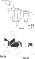
- numeral 1 designates the aerosampler.
- a gas pump 13 sucks in air from the air inlet 11, preferably equipped with a dust collector 12.
- small particle droplets entrained in the air are separated and collected as explained in in more detail with reference to Figs. 2 and 3 below.
- Wetting liquid (buffer solution) is conveyed from container 2 by means of a micropump 21 into the aerosampler.
- the buffer solution with collected droplets is conveyed to the at least one viral detection chamber 4; shown are four viral detection chambers 4 in parallel, allowing for detecting four different aeropathogens simultaneously.
- To each of the viral detection chambers 4 is assigned an electronic detection system 5 with a common oscillator 6.
- Measured signals from the viral detection chamber 4 are electronically stored and processed in a computer 7.
- An assembly of liquid containers 3 containing liquids for cleaning, rinsing and refreshing may be included in the liquid circuit by three-way valve 31. These liquids may be conveyed by a micropump 91 (suction side of the pump) to the viral detection chamber 4 and after use to a waste container 9. Pump 91 also helps conveying the buffer solution from the aerosampler 1 to the viral detection chamber 4.
- Valve 92 is open when the detection scan is made with continuously flowing buffer solution through the viral detection chamber 4 and is closed when the detection scan is made batchwise, namely non-flowing buffer solution.
- Pump 92 provides a variable flow rate of from 15 nanoliters (nL) per minute to 15 ⁇ l per minute.
- Two pumps may be installed in parallel, one allowing high flow rates and the other low flow rates, which may be run alternatively.
- air is conveyed by suction of pump 13 from air inlet 11 through micro-centrifuges 12, 15 and 16.
- Numeral 12 designates a dust filter.
- pump 13 is set at a flow rate of between 3,5 to 7,5 liters per minute (normal pressure).
- the dust outlet 17 may be equipped with a dust container 18 for collecting dust particles of diameter of above about 10 ⁇ m.
- the walls of the collector tubes 15 and 16 are wetted via line 22 from the wetting liquid container 2 ( Fig. 1 ).
- Collector tube 15 preferably mainly collects particles with a diameter of from 2 ⁇ m to 10 ⁇ m, whereas collector tube 15 is adapted to collect particles mainly with diameter up to 5 ⁇ m.
- the wetting liquid having caught particles from the air collect on the bottom of the collector tubes 15 and 16 is conveyed via line 32 to the viral detection chamber 4.
- the collector tubes preferable have a total inner volume of between 1 ml and 2,5 ml.
- Fig. 3a shows the airflow through the collector tubes 15 and 16.
- Fig. 3b shows collector tube 15 turned by 90° around its axis as compared to Fig. 3a . Air is injected in each case eccentrically and oblique to the bottom of the tube to create centrifugal force for separation of the particles entrained in the air.
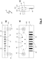
- Fig. 4 shows the viral detection chamber in detail.
- Fig. 4a shows a top view
- Fig. 4b shows a side view
- Fig. 4c shows a front view.
- the designation of top, side or front view is only for defining the relative position of Fig. 4 a), 4b) and 4c .
- the viral detection chamber may be arranged in any position, e.g. the front view may be the upper wall.
- the viral detection chamber generally designated with 4, comprises an inner cavity 41 within a housing 401, 402 with an inlet 42 and an outlet 43.
- the arrows indicate the flow direction of the fluid received from the aerosampler 1.
- the cavity 41 has a volume of between 0.5 and 1.5 mm 3 .
- a volume of between 0.6 to 1 mm 3 is particularly preferred.
- the cavity 41 has parallel upper and lower walls carrying a number of counter electrodes 44 and working electrodes 45 opposite to each other.
- counter electrodes 44 are larger than the working electrodes that are carrying the binding agent for the aeropathogens. The smaller electrodes are the working electrodes.
- the distance between the working electrodes and the opposite counter electrode preferably is between 30 ⁇ m and 50 ⁇ m.
- the diameter of the counter electrodes 44 is preferably between 50 ⁇ m and up to 100 ⁇ m.
- the diameter of the working electrodes is preferably between 0.4 to 0.7 times the diameter of the counter electrodes.
- Each pair of working electrode and the opposite counter electrode create an electric field which is perpendicular to the flow direction of liquid.
- the distance of neighbouring counter electrodes is 15 to 30 times larger than their diameter.
- the electrodes are connected to connector terminals 47 and 48 as will be explained with reference to Fig. 5 .
- An additional electrode 46 with connector terminals 49 serves as reference electrode. There is no working electrode opposite to the reference electrode. During detection the working electrodes are at a variable biasing voltage of -370 and +50 mV against the counter electrodes.
- the housing of the viral detection is composed of two plates of preferably borosilicate float glass 401 and 402. Two holes 42 and 43 are drilled through one of the plates 402. Then the cavity is prepared by a reactive ion-CF 4 plasma etch technique. It may be sufficient to provide a cavity in only one of the plates.
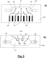
- Fig. 5 a) and b ) show the two plates 401 and 402 with their partial cavities on top.
- electrodes 44, 45 and 46, the connector terminals 47, 48 and 49 and the lines 441, 451 and 461 are applied to the plates by known photolithographic technique and deposition of noble metal vapour.
- the connecting lines 441, 451 and 461 are isolated by a suitable cover layer, e.g. of SiO 2 .
- the plates are aligned to each other as indicated by the dotted line 403 in Fig. 4c ).
- the exactly aligned plates 401 and 402 are then fused by heating to between about 500°C and 650°C under high pressure perpendicular to the fuse line 403.
- Fig. 6 is a flow chart showing the flow of the wetting fluid from the moistening container to the waste container with flow rate controllers #1 and #2 cooperating with the controller 8.
- Fig. 7 is a flow chart showing the cleaning/refreshing procedure.
- First (I) deionized water is conveyed through the device.
- cleaning liquid e.g. concentrated H 2 SO 4 is flown through the viral detection chamber 4 from one of the containers 3, followed by rinsing with deionized water from another container 3. This may be repeated several times until constant current is measured from the electrodes of the viral detection chamber 4.
- refreshing liquid is conveyed from another container 3.
- Refreshing liquid contains the functionalized aptamers (for a given aeropathogen) that will form the self-assembled monolayer on the working electrode.
- Fig. 8 shows a typical binding mechanism for aeropathogens.
- the self-assembled monolayer on the working electrode is produced according known technique.
- an amino- and thiol-modified aptamer having a methylene-blue reporter group in a 0,5 to about 1 ⁇ molar aqueous buffer solution through the viral detection chamber.
- the formula of the self-assembled monolayer of aptamers was 5'-HS-(CH 2 ) 6 -GCAGT APTAMER ACTGCT- (CH 2 ) 7 -NH 2 -MB-3'. or 5'-MB-NH 2 -(CH 2 ) 7 -TCGTCA- APTAMER - TGACG-(CH 2 ) 6 -HS-3'.
- the left picture in Fig. 8 shows a single aptamer bound to a gold surface.
- the viral detection chamber is then rinsed with deionized water to remove the buffer solution.
- the liquid from the collector tubes is fed to the viral detection chamber. If aeropathogens are present in the liquid, what is indicated by the arrow and "virus" in the middle of Fig. 8 , the aeropathogens binds to the aptamer by emitting an electron causing a response to the electronic detection system. After completion of the measurement, the viral detection chamber is rinsed with deionized water to remove all aeropathogens.
- Fig. 9 shows a typical detection cycle, wherein the x-axis represents the bias-voltage and the y-axis represents the measured current.
- the upper solid curve obtained with no virus in the air is the calibration curve taken before each detection of ambient air.
- the lower dashed curve is obtained with viruses in the air. From the difference of areas below both curves, it is possible to estimate the concentration of virus in the air. Even if the aptamer is unspecific to the aeropathogen, information on the type of aeropathogen may be obtained from position of the maximum of the upper curve on the x-axis may.
- the upper dashed curve is obtained after removal of the aeropathogens of a previous detection for calibration for the next detection cycle.
- Fig. 10 demonstrates preliminary experiments showing the electronic response of the system as a function of virus concentration.
- the detection chamber is first floated with a solution containing S1+H1N1-aptamers to cover the working electrodes with such aptamers.
- deionized water is fed from one of the containers 3 to remove any buffer solution for 5 min (time 0-300 s of the diagram).
- the current drops to 7.5 nA, corresponding to a response of 1.8 nA. Then the supply of air is stopped, the biasing voltage is set to 100 mV and a BSL-solution (Phosphate Buffer Saline) with no viruses is injected from another container 3, whereby the viral particles are released from the sensors ("flush circle") until the current returns to 9.3 nA. At the time of 900 s the BSL-solution is stopped and air with a virus concentration of 400 nMol/l is introduced into the aerosampler. The current now drops to 5.4 nA, corresponding to a response of 3,9 nA. Then this detection and flushing cycle is repeated.
- BSL-solution Phosphate Buffer Saline
- the last detection cycle is run with air containing 800 nMol/l viruses.
- the current drops to 0.8 nA, corresponding to a response of 8.5 nA. Accordingly, the response is nearly linear to the virus concentration in the air. If after a number of detection/flushing cycles the current does not return to the original value (in the example 9.3 nA) the aptamers are removed from the detection chamber by flowing concentrated H 2 SO 4 through the detection chamber with subsequent removing the acid with deionized water and renewing the aptamer coverage of the working electrodes.
Landscapes
- Chemical & Material Sciences (AREA)
- Health & Medical Sciences (AREA)
- Life Sciences & Earth Sciences (AREA)
- Immunology (AREA)
- Analytical Chemistry (AREA)
- General Health & Medical Sciences (AREA)
- Dispersion Chemistry (AREA)
- Physics & Mathematics (AREA)
- Biochemistry (AREA)
- Pathology (AREA)
- General Physics & Mathematics (AREA)
- Hematology (AREA)
- Engineering & Computer Science (AREA)
- Chemical Kinetics & Catalysis (AREA)
- Molecular Biology (AREA)
- Clinical Laboratory Science (AREA)
- Biomedical Technology (AREA)
- Urology & Nephrology (AREA)
- Virology (AREA)
- Biotechnology (AREA)
- Medicinal Chemistry (AREA)
- Food Science & Technology (AREA)
- Microbiology (AREA)
- Cell Biology (AREA)
- Tropical Medicine & Parasitology (AREA)
- Electrochemistry (AREA)
- Apparatus Associated With Microorganisms And Enzymes (AREA)
- Measuring Or Testing Involving Enzymes Or Micro-Organisms (AREA)
Claims (15)
- Vorrichtung zur Detektion von Aeropathogenen in Echtzeit, umfassend einen Aerosampler (1) mit einem Lufteinlass und mindestens einer Luftsammelröhre (15, 16); ein mikrofluidisches System, umfassend mindestens einen Behälter (2) zum Aufnehmen einer Benetzungsflüssigkeit, eine Verrohrung (22) von dem Behälter zu der mindestens einen Luftsammelröhre und mindestens eine Mikropumpe (21) zum Erzeugen eines Fluidstroms durch die Verrohrung (22); wobei der mindestens eine Behälter (2) dazu konfiguriert ist, Benetzungsflüssigkeit zu einer Innenwand der mindestens einen Sammelröhre (15, 16) zuzuführen; und wobei der Lufteinlass dazu konfiguriert ist, Luft exzentrisch und schräg zu einem Boden der Röhre in die mindestens eine Sammelröhre einzuspritzen, wodurch eine Zentrifugalkraft erzeugt wird; wobei die Vorrichtung ferner mindestens eine Aeropathogendetektionskammer (4) und eine Verrohrung von dem mikrofluidischen System zu der mindestens einen Aeropathogendetektionskammer (4) umfasst, wobei die Detektionskammer mindestens eine Arbeitselektrode (45), die mit einem funktionalisierten Aptamer zum Anbinden an ein Aeropathogen ausgestattet ist, mindestens eine Gegenelektrode (44) und mindestens eine Referenzelektrode (46) aufweist; mindestens ein elektronisches Detektionssystem (5), das mit den Elektroden der mindestens einen Aeropathogendetektionskammer verbunden werden kann; und ein eingebettetes elektronisches Verarbeitungssystem (8), das Daten verarbeitet, die von dem mindestens einen elektronischen Detektionssystem her empfangen werden können.
- Vorrichtung nach Anspruch 1, wobei der Aerosampler (1) mindestens zwei Sammelröhren (15, 16) umfasst, die in der Lage sind, zwei Größenverteilungen von Aeropathogenen gleichzeitig zu sammeln, und wobei optional das elektronische Verarbeitungssystem (8) eine Signalanalyse und Mustererkennung für die ausgewählten Pathogene ausführt.
- Vorrichtung nach Anspruch 1 oder 2, wobei eine Anzahl von 2 bis 8 Behältern (3) in der Lage sind, Flüssigkeit direkt zu der mindestens einen Aeropathogendetektionskammer (4) zuzuführen.
- Vorrichtung nach einem der vorangehenden Ansprüche, umfassend einen Staubsammler (12) und zwei Zentrifugalsammelröhren (15, 16) hintereinander in der Luftströmungsrichtung, die in der Lage sind, Partikel unterschiedlicher Größe zu sammeln.
- Vorrichtung nach einem der vorangehenden Ansprüche, wobei die Aeropathogendetektionskammer (4) eine obere und eine untere Innenwand aufweist, die parallel zueinander sind und auf denen jeweils mit einer Anzahl von 3 bis 6 Elektroden versehen sind, die zu Paaren von Elektroden, eine auf der oberen und eine auf der unteren Wand mit einer zu den Wänden senkrechten gemeinsamen Achse, gruppiert sind.
- Vorrichtung nach einem der vorangehenden Ansprüche, ferner umfassend ein elektronisches Steuersystem zum Steuern des Betriebs von Pumpen, Ventilen und des elektronischen Detektionssystems.
- Vorrichtung nach einem der vorangehenden Ansprüche, umfassend eine Anzahl von 2 bis 6 Aeropathogendetektionskammern (4), zu denen jeweils ein elektronisches Detektionssystem (5) mit einem gemeinsamen elektronischen Verarbeitungssystem (8) zugeordnet ist.
- Vorrichtung nach Anspruch 7, umfassend 4 parallele Aeropathogendetektionskammern (4), denen jeweils ein elektronisches Detektionssystem (5) mit einem gemeinsamen elektronischen Verarbeitungssystem (8) zugeordnet ist.
- Verfahren zur Detektion von Aeropathogenen in Echtzeit durch Bereitstellen eines Aerosamplers (1) mit einem Lufteinlass und umfassend mindestens eine Luftsammelröhre (15, 16); eines mikrofluidischen Systems, umfassend mindestens einen Behälter (2) zum Aufnehmen einer Benetzungsflüssigkeit, eine Verrohrung (22) von dem Behälter (2) zu der mindestens einen Luftsammelröhre (15, 16) und mindestens eine Pumpe (21) zum Erzeugen eines Fluidstroms durch die Verrohrung (22); und mindestens einer Aeropathogendetektorkammer (4) und einer Verrohrung von dem mikrofluidischen System zu der mindestens einen Aeropathogendetektionskammer; wobei der Lufteinlass (11) dazu konfiguriert ist, Luft exzentrisch und schräg zu einem Boden der Röhre (15, 16) in die mindestens eine Sammelröhre einzuspritzen, wodurch eine Zentrifugalkraft erzeugt wird, wobei die mindestens einen Aeropathogendetektionskammer (4) mindestens eine Arbeitselektrode (45), die mit einem funktionalisierten Aptamer zum Anbinden an ein Aeropathogen ausgestattet ist, und mindestens eine Referenzelektrode (46) umfasst, mindestens eines elektronischen Detektionssystems (5), das mit den Elektroden der mindestens einen Aeropathogendetektionskammer verbunden werden kann, und eines elektronischen Verarbeitungssystems (8) das Daten verarbeitet, die von dem mindestens einen elektronischen Detektionssystem her empfangen werden können, wobei das Verfahren Folgendes umfasst: Liefern von Benetzungsflüssigkeit von dem Behälter (2) zu der mindestens einen Sammelröhre (15, 16), um die Wände der mindestens einen Sammelröhre zu befeuchten, Einbringen von Luft in den Aerosampler, Sammeln von Aeropathogenen an den feuchten Wänden der mindestens einen Sammelröhre, Leiten von Feuchtigkeit von dem Wänden des Aerosamplers zu der mindestens einen Aeropathogendetektionskammer (4), Detektieren einer elektrischen Antwort zwischen den Elektroden der Aeropathogendetektionskammer und Verarbeiten der elektrischen Antwort in dem elektronischen Verarbeitungssystem, um die Anwesenheit von Aeropathogenen in der Luft zu erkennen.
- Verfahren nach Anspruch 9, ferner umfassend gleichzeitiges Sammeln von zwei Größenverteilungen von Aeropathogenpartikeln und/oder -tröpfchen mit dem Aerosampler, wobei das Verfahren optional ferner kontinuierliches Benetzen der Innenwände der mindestens einen Sammelröhre (15, 16) mit einem für die Aeropathogene, auf die abgezielt wird, geeigneten Biofluid umfasst.
- Verfahren nach Anspruch 9 oder 10, ferner umfassend wiederholtes Reinigen der Aeropathogendetektionskammer (4) mit reiner H2SO4-Säure ohne Beschädigung oder Veränderung nach Abschluss der Detektionsmessung.
- Verfahren nach Anspruch 9, 10 oder 11, ferner umfassend Steuern, unter Verwendung eines elektronischen Steuersystems, verschiedener Reinigungsabläufe des mikrofluidischen Systems für die mindestens eine Aeropathogendetektionskammer (4) und Auffrischen der Aptamere.
- Verfahren nach einem der Ansprüche 9 bis 12, ferner umfassend Nutzen eines elektrischen Felds, das zu der Strömung von Flüssigkeit durch die mindestens eine Aeropathogendetektionskammer (4) senkrecht ist.
- Verfahren nach einem der Ansprüche 9 bis 13, ferner umfassend paralleles Betreiben von 2 bis 6 Aeropathogendetektionskammern (4), um 2 bis 6 Aeropathogene gleichzeitig zu detektieren.
- Verfahren nach Anspruch 14, wobei ferner umfassend paralleles Betreiben von 4 Aeropathogendetektionskammern (4), um 4 unterschiedliche Pathogene gleichzeitig zu detektieren.
Applications Claiming Priority (1)
| Application Number | Priority Date | Filing Date | Title |
|---|---|---|---|
| PCT/CA2016/051328 WO2018090122A1 (en) | 2016-11-15 | 2016-11-15 | Device and method for real-time detection of aeropathogens |
Publications (4)
| Publication Number | Publication Date |
|---|---|
| EP3512933A1 EP3512933A1 (de) | 2019-07-24 |
| EP3512933A4 EP3512933A4 (de) | 2020-08-26 |
| EP3512933C0 EP3512933C0 (de) | 2024-07-24 |
| EP3512933B1 true EP3512933B1 (de) | 2024-07-24 |
Family
ID=62146013
Family Applications (1)
| Application Number | Title | Priority Date | Filing Date |
|---|---|---|---|
| EP16921915.1A Active EP3512933B1 (de) | 2016-11-15 | 2016-11-15 | Vorrichtung und verfahren zur echtzeit-erkennung von pathogenen in der luft |
Country Status (4)
| Country | Link |
|---|---|
| US (2) | US11635362B2 (de) |
| EP (1) | EP3512933B1 (de) |
| ES (1) | ES2987381T3 (de) |
| WO (1) | WO2018090122A1 (de) |
Families Citing this family (11)
| Publication number | Priority date | Publication date | Assignee | Title |
|---|---|---|---|---|
| GB202004723D0 (en) * | 2020-03-31 | 2020-05-13 | Osler Diagnostics Ltd | Liquid handling device |
| EP4133262A4 (de) * | 2020-04-08 | 2024-05-22 | The State of Israel - Ministry of Agriculture & Rural Development, Agricultural Research Organization (ARO) (Volcani Center) | Systeme und verfahren zur bestimmung der prävalenz von sars-cov-2 in einer population |
| CN112557364B (zh) * | 2020-12-11 | 2023-03-07 | 天津市职业大学 | 一种智能室内空气质量病毒检测系统及检测方法 |
| DE102021111494A1 (de) | 2021-05-04 | 2022-11-10 | Atral-Secal Gmbh | Nachweisgerät sowie ein Nachweisverfahren für in Luft enthaltene pathogene Substanzen |
| DE102021126818A1 (de) | 2021-10-15 | 2023-04-20 | Atral-Secal Gmbh | Nachweisgerät sowie ein Nachweisverfahren für in Luft enthaltene pathogene Substanzen |
| CN115060561A (zh) * | 2022-06-17 | 2022-09-16 | 启思半导体(杭州)有限责任公司 | 核酸样本预处理装置以及方法 |
| CN115429910A (zh) * | 2022-09-07 | 2022-12-06 | 上海长征医院 | 集成有采样机构的鞋具消毒系统 |
| CN115491298B (zh) * | 2022-10-24 | 2024-05-24 | 华北电力大学(保定) | 一种生物气溶胶用在线监测装置 |
| DE102022132609A1 (de) | 2022-12-08 | 2024-06-13 | Hager Safety Deutschland Gmbh | Nachweisgerät sowie ein Nachweisverfahren für in Luft enthaltene pathogene Substanzen |
| WO2025251064A1 (en) * | 2024-05-30 | 2025-12-04 | Goltech Llc | Automated microfluidic device for real-time monitoring of material swelling characteristics |
| DE102024206684A1 (de) | 2024-07-16 | 2026-01-22 | Hager Safety Deutschland Gmbh | Nachweisgerät sowie ein nachweisverfahren für in luft enthaltene pathogene substanzen |
Family Cites Families (8)
| Publication number | Priority date | Publication date | Assignee | Title |
|---|---|---|---|---|
| US4941899A (en) | 1989-04-24 | 1990-07-17 | Regents Of The University Of Minnesota | Cyclone personal sampler for aerosols |
| US6190548B1 (en) * | 1999-03-16 | 2001-02-20 | Albert Frick | Multi-chambered treatment filter |
| US20070186696A1 (en) * | 2002-06-24 | 2007-08-16 | Pletcher Timothy A | Self-Wetting Aerosol Particulate Wet Collector Apparatus |
| US7370543B2 (en) | 2003-10-17 | 2008-05-13 | The United States Of America As Represented By The Department Of Health And Human Services | Air-sampling device and method of use |
| ITTO20080104A1 (it) | 2008-02-08 | 2009-08-09 | Silicon Biosystems Spa | Apparato e metodo per il conteggio e l'identificazione di particelle di interesse in un fluido |
| CA2898714C (en) | 2015-07-29 | 2023-02-14 | Aerovirus Technologies Inc. | Device and method for real-time detection of aeropathogens |
| WO2017176970A1 (en) * | 2016-04-06 | 2017-10-12 | The University Of Florida Research Foundation, Inc. | Bioaerosol detection systems and methods of use |
| AU2017330304A1 (en) * | 2016-09-23 | 2019-04-11 | Alveo Technologies, Inc. | Methods and compositions for detecting analytes |
-
2016
- 2016-11-15 ES ES16921915T patent/ES2987381T3/es active Active
- 2016-11-15 US US16/342,191 patent/US11635362B2/en active Active
- 2016-11-15 WO PCT/CA2016/051328 patent/WO2018090122A1/en not_active Ceased
- 2016-11-15 EP EP16921915.1A patent/EP3512933B1/de active Active
-
2022
- 2022-01-20 US US17/580,557 patent/US11740172B2/en active Active
Also Published As
| Publication number | Publication date |
|---|---|
| US20190242807A1 (en) | 2019-08-08 |
| WO2018090122A1 (en) | 2018-05-24 |
| EP3512933C0 (de) | 2024-07-24 |
| US20220163437A1 (en) | 2022-05-26 |
| US11740172B2 (en) | 2023-08-29 |
| US11635362B2 (en) | 2023-04-25 |
| EP3512933A1 (de) | 2019-07-24 |
| EP3512933A4 (de) | 2020-08-26 |
| ES2987381T3 (es) | 2024-11-14 |
Similar Documents
| Publication | Publication Date | Title |
|---|---|---|
| US11740172B2 (en) | Device and method for real-time detection of aeropathogens | |
| Jing et al. | Microfluidic device for efficient airborne bacteria capture and enrichment | |
| Wu et al. | Portable GMR handheld platform for the detection of influenza A virus | |
| CA2898714C (en) | Device and method for real-time detection of aeropathogens | |
| US8512947B2 (en) | Detection of nucleic acids using a cantilever sensor | |
| Shen et al. | Integrating silicon nanowire field effect transistor, microfluidics and air sampling techniques for real-time monitoring biological aerosols | |
| Rastmanesh et al. | On-site bioaerosol sampling and airborne microorganism detection technologies | |
| US20220088584A1 (en) | Systems, apparatus, and methods for detecting pathogens | |
| JP2011505118A (ja) | 核酸を精製することを目的とした装置、システムおよび方法 | |
| JP2019041626A (ja) | センサ、試薬、プローブ分子の製造方法、センサの製造方法、ポリマー分子の製造方法 | |
| Sung et al. | Highly efficient in-line wet cyclone air sampler for airborne virus detection | |
| CN103443614B (zh) | 信号增强化合物在电化学发光检测中的用途 | |
| Chang et al. | Mechanisms, techniques and devices of airborne virus detection: A review | |
| Bhardwaj et al. | High enrichment and near real-time quantification of airborne viruses using a wet-paper-based electrochemical immunosensor under an electrostatic field | |
| TW202142864A (zh) | 生物氣溶膠檢測裝置 | |
| WO2013006140A1 (en) | A system and method for detecting one or more analytes in a fluid | |
| CN118403672A (zh) | 一种微流控芯片传感器、微生物检测装置及方法 | |
| Zhou et al. | Research advances in microfluidic collection and detection of virus, bacterial, and fungal bioaerosols | |
| JP2015206671A (ja) | 捕集装置、検出装置、清浄装置、捕集方法、検出方法、および、清浄方法 | |
| Feng et al. | On-site monitoring of airborne pathogens: recent advances in bioaerosol collection and rapid detection | |
| CN116879353A (zh) | 一种实时直接气相检测微生物的传感器、检测系统及方法 | |
| Lin et al. | Biomedical devices for pathogen detection using microfluidic chips | |
| Singh et al. | Mechanical desorption of immobilized proteins using carbon dioxide aerosols for reusable biosensors | |
| De Penning et al. | From Aerosol to Signal: Advances in Biosensor Technologies for Airborne Biothreat Detection | |
| Cao et al. | Technologies and Applications |
Legal Events
| Date | Code | Title | Description |
|---|---|---|---|
| STAA | Information on the status of an ep patent application or granted ep patent |
Free format text: STATUS: THE INTERNATIONAL PUBLICATION HAS BEEN MADE |
|
| PUAI | Public reference made under article 153(3) epc to a published international application that has entered the european phase |
Free format text: ORIGINAL CODE: 0009012 |
|
| STAA | Information on the status of an ep patent application or granted ep patent |
Free format text: STATUS: REQUEST FOR EXAMINATION WAS MADE |
|
| 17P | Request for examination filed |
Effective date: 20190415 |
|
| AK | Designated contracting states |
Kind code of ref document: A1 Designated state(s): AL AT BE BG CH CY CZ DE DK EE ES FI FR GB GR HR HU IE IS IT LI LT LU LV MC MK MT NL NO PL PT RO RS SE SI SK SM TR |
|
| AX | Request for extension of the european patent |
Extension state: BA ME |
|
| DAV | Request for validation of the european patent (deleted) | ||
| DAX | Request for extension of the european patent (deleted) | ||
| RIC1 | Information provided on ipc code assigned before grant |
Ipc: G01N 33/569 20060101ALI20200409BHEP Ipc: B01L 3/00 20060101ALI20200409BHEP Ipc: G01N 15/02 20060101ALI20200409BHEP Ipc: C12Q 1/70 20060101ALI20200409BHEP Ipc: G01N 27/416 20060101ALI20200409BHEP Ipc: C12M 1/34 20060101AFI20200409BHEP Ipc: G01N 1/22 20060101ALI20200409BHEP |
|
| A4 | Supplementary search report drawn up and despatched |
Effective date: 20200723 |
|
| RIC1 | Information provided on ipc code assigned before grant |
Ipc: B01L 3/00 20060101ALI20200718BHEP Ipc: G01N 15/02 20060101ALI20200718BHEP Ipc: G01N 27/416 20060101ALI20200718BHEP Ipc: C12Q 1/70 20060101ALI20200718BHEP Ipc: C12M 1/34 20060101AFI20200718BHEP Ipc: G01N 1/22 20060101ALI20200718BHEP Ipc: G01N 33/569 20060101ALI20200718BHEP |
|
| STAA | Information on the status of an ep patent application or granted ep patent |
Free format text: STATUS: EXAMINATION IS IN PROGRESS |
|
| 17Q | First examination report despatched |
Effective date: 20220705 |
|
| GRAP | Despatch of communication of intention to grant a patent |
Free format text: ORIGINAL CODE: EPIDOSNIGR1 |
|
| STAA | Information on the status of an ep patent application or granted ep patent |
Free format text: STATUS: GRANT OF PATENT IS INTENDED |
|
| INTG | Intention to grant announced |
Effective date: 20240213 |
|
| GRAS | Grant fee paid |
Free format text: ORIGINAL CODE: EPIDOSNIGR3 |
|
| GRAA | (expected) grant |
Free format text: ORIGINAL CODE: 0009210 |
|
| STAA | Information on the status of an ep patent application or granted ep patent |
Free format text: STATUS: THE PATENT HAS BEEN GRANTED |
|
| AK | Designated contracting states |
Kind code of ref document: B1 Designated state(s): AL AT BE BG CH CY CZ DE DK EE ES FI FR GB GR HR HU IE IS IT LI LT LU LV MC MK MT NL NO PL PT RO RS SE SI SK SM TR |
|
| REG | Reference to a national code |
Ref country code: GB Ref legal event code: FG4D |
|
| REG | Reference to a national code |
Ref country code: CH Ref legal event code: EP |
|
| REG | Reference to a national code |
Ref country code: IE Ref legal event code: FG4D Ref country code: DE Ref legal event code: R096 Ref document number: 602016088595 Country of ref document: DE |
|
| U01 | Request for unitary effect filed |
Effective date: 20240823 |
|
| U07 | Unitary effect registered |
Designated state(s): AT BE BG DE DK EE FI FR IT LT LU LV MT NL PT RO SE SI Effective date: 20240902 |
|
| REG | Reference to a national code |
Ref country code: ES Ref legal event code: FG2A Ref document number: 2987381 Country of ref document: ES Kind code of ref document: T3 Effective date: 20241114 |
|
| U20 | Renewal fee for the european patent with unitary effect paid |
Year of fee payment: 9 Effective date: 20241106 |
|
| PG25 | Lapsed in a contracting state [announced via postgrant information from national office to epo] |
Ref country code: NO Free format text: LAPSE BECAUSE OF FAILURE TO SUBMIT A TRANSLATION OF THE DESCRIPTION OR TO PAY THE FEE WITHIN THE PRESCRIBED TIME-LIMIT Effective date: 20241024 |
|
| PG25 | Lapsed in a contracting state [announced via postgrant information from national office to epo] |
Ref country code: PL Free format text: LAPSE BECAUSE OF FAILURE TO SUBMIT A TRANSLATION OF THE DESCRIPTION OR TO PAY THE FEE WITHIN THE PRESCRIBED TIME-LIMIT Effective date: 20240724 Ref country code: GR Free format text: LAPSE BECAUSE OF FAILURE TO SUBMIT A TRANSLATION OF THE DESCRIPTION OR TO PAY THE FEE WITHIN THE PRESCRIBED TIME-LIMIT Effective date: 20241025 |
|
| PG25 | Lapsed in a contracting state [announced via postgrant information from national office to epo] |
Ref country code: IS Free format text: LAPSE BECAUSE OF FAILURE TO SUBMIT A TRANSLATION OF THE DESCRIPTION OR TO PAY THE FEE WITHIN THE PRESCRIBED TIME-LIMIT Effective date: 20241124 |
|
| PG25 | Lapsed in a contracting state [announced via postgrant information from national office to epo] |
Ref country code: HR Free format text: LAPSE BECAUSE OF FAILURE TO SUBMIT A TRANSLATION OF THE DESCRIPTION OR TO PAY THE FEE WITHIN THE PRESCRIBED TIME-LIMIT Effective date: 20240724 |
|
| PG25 | Lapsed in a contracting state [announced via postgrant information from national office to epo] |
Ref country code: RS Free format text: LAPSE BECAUSE OF FAILURE TO SUBMIT A TRANSLATION OF THE DESCRIPTION OR TO PAY THE FEE WITHIN THE PRESCRIBED TIME-LIMIT Effective date: 20241024 |
|
| PGFP | Annual fee paid to national office [announced via postgrant information from national office to epo] |
Ref country code: ES Payment date: 20241204 Year of fee payment: 9 |
|
| PG25 | Lapsed in a contracting state [announced via postgrant information from national office to epo] |
Ref country code: RS Free format text: LAPSE BECAUSE OF FAILURE TO SUBMIT A TRANSLATION OF THE DESCRIPTION OR TO PAY THE FEE WITHIN THE PRESCRIBED TIME-LIMIT Effective date: 20241024 Ref country code: PL Free format text: LAPSE BECAUSE OF FAILURE TO SUBMIT A TRANSLATION OF THE DESCRIPTION OR TO PAY THE FEE WITHIN THE PRESCRIBED TIME-LIMIT Effective date: 20240724 Ref country code: NO Free format text: LAPSE BECAUSE OF FAILURE TO SUBMIT A TRANSLATION OF THE DESCRIPTION OR TO PAY THE FEE WITHIN THE PRESCRIBED TIME-LIMIT Effective date: 20241024 Ref country code: IS Free format text: LAPSE BECAUSE OF FAILURE TO SUBMIT A TRANSLATION OF THE DESCRIPTION OR TO PAY THE FEE WITHIN THE PRESCRIBED TIME-LIMIT Effective date: 20241124 Ref country code: HR Free format text: LAPSE BECAUSE OF FAILURE TO SUBMIT A TRANSLATION OF THE DESCRIPTION OR TO PAY THE FEE WITHIN THE PRESCRIBED TIME-LIMIT Effective date: 20240724 Ref country code: GR Free format text: LAPSE BECAUSE OF FAILURE TO SUBMIT A TRANSLATION OF THE DESCRIPTION OR TO PAY THE FEE WITHIN THE PRESCRIBED TIME-LIMIT Effective date: 20241025 |
|
| PG25 | Lapsed in a contracting state [announced via postgrant information from national office to epo] |
Ref country code: SM Free format text: LAPSE BECAUSE OF FAILURE TO SUBMIT A TRANSLATION OF THE DESCRIPTION OR TO PAY THE FEE WITHIN THE PRESCRIBED TIME-LIMIT Effective date: 20240724 |
|
| PG25 | Lapsed in a contracting state [announced via postgrant information from national office to epo] |
Ref country code: CZ Free format text: LAPSE BECAUSE OF FAILURE TO SUBMIT A TRANSLATION OF THE DESCRIPTION OR TO PAY THE FEE WITHIN THE PRESCRIBED TIME-LIMIT Effective date: 20240724 |
|
| PG25 | Lapsed in a contracting state [announced via postgrant information from national office to epo] |
Ref country code: SK Free format text: LAPSE BECAUSE OF FAILURE TO SUBMIT A TRANSLATION OF THE DESCRIPTION OR TO PAY THE FEE WITHIN THE PRESCRIBED TIME-LIMIT Effective date: 20240724 |
|
| PLBE | No opposition filed within time limit |
Free format text: ORIGINAL CODE: 0009261 |
|
| STAA | Information on the status of an ep patent application or granted ep patent |
Free format text: STATUS: NO OPPOSITION FILED WITHIN TIME LIMIT |
|
| REG | Reference to a national code |
Ref country code: CH Ref legal event code: PL |
|
| 26N | No opposition filed |
Effective date: 20250425 |
|
| PG25 | Lapsed in a contracting state [announced via postgrant information from national office to epo] |
Ref country code: MC Free format text: LAPSE BECAUSE OF FAILURE TO SUBMIT A TRANSLATION OF THE DESCRIPTION OR TO PAY THE FEE WITHIN THE PRESCRIBED TIME-LIMIT Effective date: 20240724 |
|
| REG | Reference to a national code |
Ref country code: CH Ref legal event code: PL |
|
| GBPC | Gb: european patent ceased through non-payment of renewal fee |
Effective date: 20241115 |
|
| PG25 | Lapsed in a contracting state [announced via postgrant information from national office to epo] |
Ref country code: CH Free format text: LAPSE BECAUSE OF NON-PAYMENT OF DUE FEES Effective date: 20241130 |
|
| PG25 | Lapsed in a contracting state [announced via postgrant information from national office to epo] |
Ref country code: GB Free format text: LAPSE BECAUSE OF NON-PAYMENT OF DUE FEES Effective date: 20241115 |
|
| PG25 | Lapsed in a contracting state [announced via postgrant information from national office to epo] |
Ref country code: IE Free format text: LAPSE BECAUSE OF NON-PAYMENT OF DUE FEES Effective date: 20241115 |
|
| U20 | Renewal fee for the european patent with unitary effect paid |
Year of fee payment: 10 Effective date: 20251126 |