EP3512050A1 - Landseitiger elektrofahrzeug-ladestecker - Google Patents
Landseitiger elektrofahrzeug-ladestecker Download PDFInfo
- Publication number
- EP3512050A1 EP3512050A1 EP18020556.9A EP18020556A EP3512050A1 EP 3512050 A1 EP3512050 A1 EP 3512050A1 EP 18020556 A EP18020556 A EP 18020556A EP 3512050 A1 EP3512050 A1 EP 3512050A1
- Authority
- EP
- European Patent Office
- Prior art keywords
- interface
- electric vehicle
- base
- connector
- vehicle charging
- Prior art date
- Legal status (The legal status is an assumption and is not a legal conclusion. Google has not performed a legal analysis and makes no representation as to the accuracy of the status listed.)
- Granted
Links
Images
Classifications
-
- H—ELECTRICITY
- H01—ELECTRIC ELEMENTS
- H01R—ELECTRICALLY-CONDUCTIVE CONNECTIONS; STRUCTURAL ASSOCIATIONS OF A PLURALITY OF MUTUALLY-INSULATED ELECTRICAL CONNECTING ELEMENTS; COUPLING DEVICES; CURRENT COLLECTORS
- H01R13/00—Details of coupling devices of the kinds covered by groups H01R12/70 or H01R24/00 - H01R33/00
- H01R13/46—Bases; Cases
- H01R13/502—Bases; Cases composed of different pieces
-
- B—PERFORMING OPERATIONS; TRANSPORTING
- B60—VEHICLES IN GENERAL
- B60L—PROPULSION OF ELECTRICALLY-PROPELLED VEHICLES; SUPPLYING ELECTRIC POWER FOR AUXILIARY EQUIPMENT OF ELECTRICALLY-PROPELLED VEHICLES; ELECTRODYNAMIC BRAKE SYSTEMS FOR VEHICLES IN GENERAL; MAGNETIC SUSPENSION OR LEVITATION FOR VEHICLES; MONITORING OPERATING VARIABLES OF ELECTRICALLY-PROPELLED VEHICLES; ELECTRIC SAFETY DEVICES FOR ELECTRICALLY-PROPELLED VEHICLES
- B60L53/00—Methods of charging batteries, specially adapted for electric vehicles; Charging stations or on-board charging equipment therefor; Exchange of energy storage elements in electric vehicles
- B60L53/10—Methods of charging batteries, specially adapted for electric vehicles; Charging stations or on-board charging equipment therefor; Exchange of energy storage elements in electric vehicles characterised by the energy transfer between the charging station and the vehicle
- B60L53/14—Conductive energy transfer
- B60L53/16—Connectors, e.g. plugs or sockets, specially adapted for charging electric vehicles
-
- H—ELECTRICITY
- H01—ELECTRIC ELEMENTS
- H01R—ELECTRICALLY-CONDUCTIVE CONNECTIONS; STRUCTURAL ASSOCIATIONS OF A PLURALITY OF MUTUALLY-INSULATED ELECTRICAL CONNECTING ELEMENTS; COUPLING DEVICES; CURRENT COLLECTORS
- H01R13/00—Details of coupling devices of the kinds covered by groups H01R12/70 or H01R24/00 - H01R33/00
- H01R13/46—Bases; Cases
- H01R13/502—Bases; Cases composed of different pieces
- H01R13/506—Bases; Cases composed of different pieces assembled by snap action of the parts
-
- H—ELECTRICITY
- H01—ELECTRIC ELEMENTS
- H01R—ELECTRICALLY-CONDUCTIVE CONNECTIONS; STRUCTURAL ASSOCIATIONS OF A PLURALITY OF MUTUALLY-INSULATED ELECTRICAL CONNECTING ELEMENTS; COUPLING DEVICES; CURRENT COLLECTORS
- H01R13/00—Details of coupling devices of the kinds covered by groups H01R12/70 or H01R24/00 - H01R33/00
- H01R13/46—Bases; Cases
- H01R13/502—Bases; Cases composed of different pieces
- H01R13/512—Bases; Cases composed of different pieces assembled by screw or screws
-
- H—ELECTRICITY
- H01—ELECTRIC ELEMENTS
- H01R—ELECTRICALLY-CONDUCTIVE CONNECTIONS; STRUCTURAL ASSOCIATIONS OF A PLURALITY OF MUTUALLY-INSULATED ELECTRICAL CONNECTING ELEMENTS; COUPLING DEVICES; CURRENT COLLECTORS
- H01R13/00—Details of coupling devices of the kinds covered by groups H01R12/70 or H01R24/00 - H01R33/00
- H01R13/62—Means for facilitating engagement or disengagement of coupling parts or for holding them in engagement
- H01R13/621—Bolt, set screw or screw clamp
- H01R13/6215—Bolt, set screw or screw clamp using one or more bolts
-
- H—ELECTRICITY
- H01—ELECTRIC ELEMENTS
- H01R—ELECTRICALLY-CONDUCTIVE CONNECTIONS; STRUCTURAL ASSOCIATIONS OF A PLURALITY OF MUTUALLY-INSULATED ELECTRICAL CONNECTING ELEMENTS; COUPLING DEVICES; CURRENT COLLECTORS
- H01R13/00—Details of coupling devices of the kinds covered by groups H01R12/70 or H01R24/00 - H01R33/00
- H01R13/62—Means for facilitating engagement or disengagement of coupling parts or for holding them in engagement
- H01R13/629—Additional means for facilitating engagement or disengagement of coupling parts, e.g. aligning or guiding means, levers, gas pressure electrical locking indicators, manufacturing tolerances
-
- H—ELECTRICITY
- H01—ELECTRIC ELEMENTS
- H01R—ELECTRICALLY-CONDUCTIVE CONNECTIONS; STRUCTURAL ASSOCIATIONS OF A PLURALITY OF MUTUALLY-INSULATED ELECTRICAL CONNECTING ELEMENTS; COUPLING DEVICES; CURRENT COLLECTORS
- H01R13/00—Details of coupling devices of the kinds covered by groups H01R12/70 or H01R24/00 - H01R33/00
- H01R13/62—Means for facilitating engagement or disengagement of coupling parts or for holding them in engagement
- H01R13/629—Additional means for facilitating engagement or disengagement of coupling parts, e.g. aligning or guiding means, levers, gas pressure electrical locking indicators, manufacturing tolerances
- H01R13/631—Additional means for facilitating engagement or disengagement of coupling parts, e.g. aligning or guiding means, levers, gas pressure electrical locking indicators, manufacturing tolerances for engagement only
-
- H—ELECTRICITY
- H01—ELECTRIC ELEMENTS
- H01R—ELECTRICALLY-CONDUCTIVE CONNECTIONS; STRUCTURAL ASSOCIATIONS OF A PLURALITY OF MUTUALLY-INSULATED ELECTRICAL CONNECTING ELEMENTS; COUPLING DEVICES; CURRENT COLLECTORS
- H01R27/00—Coupling parts adapted for co-operation with two or more dissimilar counterparts
-
- H—ELECTRICITY
- H01—ELECTRIC ELEMENTS
- H01R—ELECTRICALLY-CONDUCTIVE CONNECTIONS; STRUCTURAL ASSOCIATIONS OF A PLURALITY OF MUTUALLY-INSULATED ELECTRICAL CONNECTING ELEMENTS; COUPLING DEVICES; CURRENT COLLECTORS
- H01R31/00—Coupling parts supported only by co-operation with counterpart
- H01R31/06—Intermediate parts for linking two coupling parts, e.g. adapter
-
- H—ELECTRICITY
- H01—ELECTRIC ELEMENTS
- H01R—ELECTRICALLY-CONDUCTIVE CONNECTIONS; STRUCTURAL ASSOCIATIONS OF A PLURALITY OF MUTUALLY-INSULATED ELECTRICAL CONNECTING ELEMENTS; COUPLING DEVICES; CURRENT COLLECTORS
- H01R2201/00—Connectors or connections adapted for particular applications
- H01R2201/26—Connectors or connections adapted for particular applications for vehicles
-
- Y—GENERAL TAGGING OF NEW TECHNOLOGICAL DEVELOPMENTS; GENERAL TAGGING OF CROSS-SECTIONAL TECHNOLOGIES SPANNING OVER SEVERAL SECTIONS OF THE IPC; TECHNICAL SUBJECTS COVERED BY FORMER USPC CROSS-REFERENCE ART COLLECTIONS [XRACs] AND DIGESTS
- Y02—TECHNOLOGIES OR APPLICATIONS FOR MITIGATION OR ADAPTATION AGAINST CLIMATE CHANGE
- Y02T—CLIMATE CHANGE MITIGATION TECHNOLOGIES RELATED TO TRANSPORTATION
- Y02T10/00—Road transport of goods or passengers
- Y02T10/60—Other road transportation technologies with climate change mitigation effect
- Y02T10/70—Energy storage systems for electromobility, e.g. batteries
-
- Y—GENERAL TAGGING OF NEW TECHNOLOGICAL DEVELOPMENTS; GENERAL TAGGING OF CROSS-SECTIONAL TECHNOLOGIES SPANNING OVER SEVERAL SECTIONS OF THE IPC; TECHNICAL SUBJECTS COVERED BY FORMER USPC CROSS-REFERENCE ART COLLECTIONS [XRACs] AND DIGESTS
- Y02—TECHNOLOGIES OR APPLICATIONS FOR MITIGATION OR ADAPTATION AGAINST CLIMATE CHANGE
- Y02T—CLIMATE CHANGE MITIGATION TECHNOLOGIES RELATED TO TRANSPORTATION
- Y02T10/00—Road transport of goods or passengers
- Y02T10/60—Other road transportation technologies with climate change mitigation effect
- Y02T10/7072—Electromobility specific charging systems or methods for batteries, ultracapacitors, supercapacitors or double-layer capacitors
-
- Y—GENERAL TAGGING OF NEW TECHNOLOGICAL DEVELOPMENTS; GENERAL TAGGING OF CROSS-SECTIONAL TECHNOLOGIES SPANNING OVER SEVERAL SECTIONS OF THE IPC; TECHNICAL SUBJECTS COVERED BY FORMER USPC CROSS-REFERENCE ART COLLECTIONS [XRACs] AND DIGESTS
- Y02—TECHNOLOGIES OR APPLICATIONS FOR MITIGATION OR ADAPTATION AGAINST CLIMATE CHANGE
- Y02T—CLIMATE CHANGE MITIGATION TECHNOLOGIES RELATED TO TRANSPORTATION
- Y02T90/00—Enabling technologies or technologies with a potential or indirect contribution to GHG emissions mitigation
- Y02T90/10—Technologies relating to charging of electric vehicles
- Y02T90/14—Plug-in electric vehicles
Definitions
- the invention relates to a shore-side electric vehicle charging plug, which can be inserted for charging a vehicle-side traction battery in a vehicle-side charging plug.
- the shore-side electric vehicle charging plug is part of a shore-side charging station for charging a traction battery of an electric vehicle.
- the shore-side charging plug is exposed to high wear, since it is used several hundred times to several thousand times a year, that is coupled and disconnected.
- the pure wear of the electrical contacts of the charging plug is also mechanically stressed and possibly mechanically damaged, for example by falling down and hitting the ground.
- the shore-side charging plugs are therefore replaced at regular intervals. This can be done, for example, by replacing the entire charging cable including the attached shore-side charging plug. For this purpose, however, the charging station must be opened and the new charging cable with its charging point end connected to the charging station.
- Out CN 105896212 A is a landside electric vehicle charging plug known with the an adapter plug can be converted to another connector standard.
- the adapter plug has several firmly anchored in the adapter plug adapter contacts, which must be plugged together when plugging the adapter plug on the plug base with the corresponding base contacts. If the mutually corresponding contacts when plugging not exactly aligned with each other axially, the mating is very difficult. Further, the mating contact ends of the adapter contacts and the corresponding base contacts can be deformed or damaged in poor alignment during mating. If the contacts are charging current contacts, poor contact due to the relatively high ohmic resistance can lead to excessive heating at high charging currents.
- the object of the invention is in contrast to provide a shore-side electric vehicle charging plug with simple and reliable interchangeability of the electrical contacts.
- the shore-side electric vehicle charging connector has a connector base and a separate replaceable interface which is attached to the connector base, but can be replaced with a few simple steps.
- the connector base has at least one electrically non-conductive base body and at least one charging current base contact, which is attached to or in the base body.
- the charging current base contact is, for example, molded positively in the base body.
- the interface has an electrically non-conductive interface body and at least one charge current interface contact mounted in or on the interface body.
- the charging current interface contact is plugged together in the assembled state of the interface with the corresponding charging base contact or in this plugged in.
- Under a charging current contact is generally an electrically conductive contact body to understand, flows through the charging current through which the traction battery of the electric vehicle is charged.
- the direction proximal to the proximal direction is always to be understood as meaning the direction of the charging column, while the direction opposite to the opposite direction facing the vehicle-side charging plug is to be understood as meaning the distal direction.
- the connector base and the interface have forced guiding means which form a threading funnel and which particularly preferably allow an initial angular deviation of the interface to the connector base of more than 10 ° when plugging the interface and the connector base in a positive guide plane and finally to less than 5 ° to reduce.
- the positive guidance means can be formed in a variety of ways on the connector base and the interface, and allow for the installation of a new and unverschlissenen interface on the connector base that the interface can be placed relative to the positive guide plane initially with a certain rotational inaccuracy on the connector base.
- the threading funnel ensures that the initial actual angular deviation is finally reduced to a small angle.
- the forced guiding means is designed such that the contact angle deviation at the time in which the charging current interface contact and the charging current base contact are electrically contacted when plugged together is less than 10 °, particularly preferred less than 5 °. In the moment in which the two charging current contacts come into mechanical contact with each other, so the angle deviation is reduced so that the two contacts interlock and can be further pushed together sliding, but not blocking each other.
- an elastic guide means is provided, which is designed such that it elastically counteracts an initial angular deviation in the spring plane in a spring plane which is perpendicular to the positive guide plane.
- the elastic guide means may be designed such that with increasing proximity of the interface to the base body, the spring force in the spring plane increases such that it is finally a positive guidance, especially at the moment in which the two corresponding charging current contacts eventually touch and be pushed into each other.
- the forced guide means is designed as a tab body, which engages when mating in a corresponding tab guide.
- the positive guide plane is preferably located in the ground plane of the flat-shaped tab body.
- the elastic guide means is designed as a tab body, which is guided by a corresponding tab guide.
- the spring plane is preferably oriented perpendicular to the ground plane of the tab body.
- the tab guide may in particular be designed as a guide surface against which the tab body lies flat.
- a guide means two lateral tab body are provided, which act complementary and / or redundant.
- Each of the two tab bodies particularly preferably defines both an elastic guide means and a forced guide means.
- the two tab bodies can interact as an elastic guide means antagonistic with each other.
- the tab body or the two tab bodies basically have an additional stabilizing effect with respect to lateral impacts on the interface, as they can occur, for example, when the charging plug hits the ground.
- the tab body tapers proximally, and preferably tapers in a single or double involute.
- the compulsory guide means corresponding thereto can likewise be correspondingly tapered. This results in a forced guidance, which initially enforces a relatively large angle correction and finally a relatively small angle correction.
- the tab body or the two tab body associated with the interface whereas the corresponding positive guide means are assigned in the form of grooves and / or recesses of the connector base.
- a securing element is provided, by which the interface is fixed to the connector base.
- the fuse element can not be opened without tools.
- the tool may for example be a special tool, so that unauthorized removal of the fuse element is difficult or impossible.
- Such a security element may for example be a lock that can only be opened with a corresponding key.
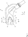
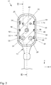
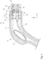
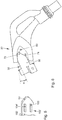
- FIGS. 1 . 3 and 4 an assembled shore-side electric vehicle charging connector 10 is shown, which is suitable for insertion into a corresponding vehicle-side charging connector (not shown) to charge a traction battery of an electric vehicle.
- the charging plug 10 has a handle portion 13 which is formed by a handle portion housing 16 and defines a handle opening 15 which can be grasped by the hand of an operator.
- a connector base 20 is firmly anchored.
- the plug base 20 is formed by an electrically non-conductive plastic base body 22, two fixed in the base body 22 charging current base contacts 24 and two signal base contacts 26. All the base contacts 24, 26 are firmly anchored in the base body 22 in such a way that they can not be removed from the base body 22 without damage or destruction of the base body 22.
- the plug base 20 remains over the entire life of the charging plug 10 on the handle housing 16 without being replaced.
- the charging current base contacts 24 are electrically connected via an electrical charging line 12 to a shore-side charging station (not shown).
- the signal base contacts 26 are each over a corresponding signal line 14 connected to the shore-side charging station. Charging currents of several 100 A are transmitted via the charging lines 12. About the signal lines 14 only electrical signals are transmitted.
- the interface 30 Attached to the connector base 20 is a separate removable interface 30 exposed to relatively high mechanical wear in the field.
- the interface 30 can be replaced with relatively little effort if necessary, for example in the context of regular maintenance.
- the interface 30 has an electrically non-conductive plastic interface body 32 in which two charging current interface contacts 34 and two signal interface contacts 36 are fixed or molded positively. All contacts 24,26,34,36 are electrically conductive and each consist of a metal suitable for this purpose.
- the interface 30 or the interface body 32 is fixed with a securing element 40 on the plug base 20 or the base body 22.
- the securing element 40 is presently a head threaded screw which is inserted deep sunk in an axial stepped bore 38 of the interface body 32, and which is screwed with its threaded shaft in a corresponding threaded bore 39 of the base body 22.
- the securing element 40 has a screw head, which can be positively contacted with a corresponding special tool, so that the securing element 40 can be screwed in or out only with the special tool.
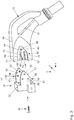
- the plug base 20 and the interface 30 have forced guide means, which have a funnel-shaped design and the plugging in the interface 30 on the connector base 20, as shown in the FIG. 2 is indicated in a forced guidance level XY, which in the FIG. 4 corresponding longitudinal section plane, allow an initial angle deviation of present more than 20 ° and final, as in FIG. 1 shown, reduce to less than 5 °.
- the interface 30 has as vertical forced guide means 50,50 'two tab body 52,52 ', which may for example be integrally formed with the interface body 32 made of plastic.
- the two tab bodies 52, 52 'furthermore also define lateral elastic guide means 50, 50' and therefore have a double function.
- the compulsory guide means include a plurality of elements, namely, in particular, the tab body edges 51, 51 ', 53, 53', which force-fit with the corresponding tab guides 60, 63, 64, 65 of a corresponding tab guide 60 designed as a flat recess 60 ' cooperate, and per tab body 52 in each case two guide knobs 54,55,54 ', which interact positively with two corresponding guide grooves 70,71 in the flat recess 60' of the tab guide 60 during assembly.
- a detent bore 80 is provided, into which a corresponding detent knob 56, 56' engages on the inside of the tab body 52, 52 'in the final assembly position of the interface 30, as in FIG FIG. 3 is recognizable.
- the two tab bodies 52, 52 ' are designed to taper in the proximal direction, wherein the taper 53, 53' is designed in each case as a double involute.
- the proximal end portion 64,65 of the flat recess 60 'of the tab guide 60 is also tapered in the form of a double involute so that the two tab bodies 52,52' completely fill the corresponding tab guide recess 60 ', as in the FIG. 1 shown.
- a new and unworn interface 30 is provided for mounting to the connector base 20 as shown in FIG FIG. 2 shown.
- the interface 30 is first approximately axially aligned with the connector base 20 by an assembler, and then slid axially onto the connector base 20.
- the forced guiding means ensure that the initial angular deviation in the positive guidance plane XY is less than 25 °.
- the tab bodies 52,52 'rest on the base 61 in the recess 60' so as to elastically counteract an initial angular deviation in the spring plane YZ in a spring plane YZ perpendicular to the positive guide plane XY and to the connector base 20 align.
- the angular deviation between the plug base 20 and the interface 30 is continuously reduced during the further assembly movement.
- the maximum contact angle deviation is only a few degrees, for example less than 5 °.
- FIG. 5 By way of example, an alternative embodiment of a tab body 152 'of the guide means 150' is shown, which has two parallel guide webs 154 ', 155' instead of guide studs.
- the initial angular deviation a is shown in the initial mating of the connector base 20 with the interface 30.
- the initial angular deviation a is presently about 20 °.
Landscapes
- Engineering & Computer Science (AREA)
- Power Engineering (AREA)
- Transportation (AREA)
- Mechanical Engineering (AREA)
- Details Of Connecting Devices For Male And Female Coupling (AREA)
- Electric Propulsion And Braking For Vehicles (AREA)
- Charge And Discharge Circuits For Batteries Or The Like (AREA)
Abstract
Description
- Die Erfindung bezieht sich auf einen landseitigen Elektrofahrzeug-Ladestecker, der zum Aufladen einer fahrzeugseitigen Traktionsbatterie in einen fahrzeugseitigen Ladestecker einsteckbar ist.
- Der landseitige Elektrofahrzeug-Ladestecker ist Teil einer landseitigen Ladestation zum Aufladen einer Traktionsbatterie eines Elektrofahrzeugs. Im Gegensatz zum fahrzeugseitigen Ladestecker ist der landseitige Ladestecker einem hohen Verschleiß ausgesetzt, da er mehrere 100-mal bis zu mehreren 1000-mal pro Jahr benutzt wird, also angekoppelt und abgekoppelt wird. Neben dem reinen Verschleiß der elektrischen Kontakte wird der Ladestecker im Übrigen auch mechanisch beansprucht und gegebenenfalls mechanisch beschädigt, beispielsweise durch Herunterfallen und Aufschlagen auf den Boden.
- Die landseitigen Ladestecker werden daher in regelmäßigen Abständen ausgetauscht. Dies kann beispielsweise dadurch erfolgen, dass das gesamte Ladekabel einschließlich des daran befestigten landseitigen Ladesteckers ausgetauscht wird. Hierzu muss jedoch die Ladesäule geöffnet werden und das neue Ladekabel mit seinem ladesäulenseitigen Ende an die Ladesäule angeschlossen werden.
- Alternativ werden an dem landseitigen Ladestecker nur die elektrischen Kontakte ausgetauscht. Hierzu müssen die korrespondierenden Leitungskabel entsprechend gekürzt werden, um an den gekürzten Kabelenden die neuen elektrischen Kontakte befestigen zu können, beispielsweise durch Löten oder Crimpen. Dieses Verfahren ist umständlich und sehr anfällig für eine mangelhafte Umsetzung, da die Qualität des auf diese Weise überarbeiteten Ladesteckers sehr von der Sorgfalt des Monteurs abhängig ist.
- Aus
CN 105896212 A ist ein landseitiger Elektrofahrzeug-Ladestecker bekannt, der mit einem Adapterstecker auf eine andere Anschlussstecker-Norm umgerüstet werden kann. Der Adapterstecker weist mehrere fest in dem Adapterstecker verankerte Adapterkontakte auf, die beim Aufstecken des Adaptersteckers auf die Steckerbasis mit den korrespondierenden Basiskontakten zusammengesteckt werden müssen. Wenn die miteinander korrespondierenden Kontakte beim Aufstecken nicht exakt axial miteinander fluchten, ist das Zusammenstecken sehr erschwert. Ferner können die aufeinander treffenden Kontaktenden der Adapterkontakte und der korrespondierenden Basiskontakte bei schlechter Ausrichtung beim Zusammenstecken deformiert bzw. beschädigt werden. Wenn es sich bei den Kontakten um Ladestrom-Kontakte handelt, kann eine schlechte Kontaktierung wegen des relativ hohen ohmschen Widerstands zu starker Erwärmung bei hohen Ladeströmen führen. - Aufgabe der Erfindung ist es demgegenüber, einen landseitigen Elektrofahrzeug-Ladestecker mit einfacher und zuverlässiger Austauschbarkeit der elektrischen Kontakte zu schaffen.
- Diese Aufgabe wird erfindungsgemäß gelöst mit einem landseitigen Elektrofahrzeug-Ladestecker mit den Merkmalen des Anspruchs 1.
- Der erfindungsgemäße landseitige Elektrofahrzeug-Ladestecker weist eine Steckerbasis und ein separates austauschbares Interface auf, das an der Steckerbasis befestigt ist, jedoch mit wenigen Handgriffen ausgetauscht werden kann. Die Steckerbasis weist mindestens einen elektrisch nicht-leitenden Basiskörper und mindestens einen Ladestrom-Basiskontakt auf, der an dem bzw. in dem Basiskörper befestigt ist. Der Ladestrom-Basiskontakt ist beispielsweise formschlüssig in dem Basiskörper vergossen.
- Das Interface weist einen elektrisch nicht-leitenden Interfacekörper und mindestens einen in oder an dem Interfacekörper befestigten Ladestrom-Interfacekontakt auf. Der Ladestrom-Interfacekontakt ist im montierten Zustand des Interface mit dem korrespondierenden Ladestrom-Basiskontakt zusammengesteckt bzw. in diesen eingesteckt. Unter einem Ladestrom-Kontakt ist generell ein elektrisch leitender Kontaktkörper zu verstehen, über den der Ladestrom fließt, durch den die Traktionsbatterie des Elektrofahrzeugs aufgeladen wird.
- Unter der proximalen Richtung ist vorliegend stets die der Ladesäule zugewandte Richtung zu verstehen, wohingegen unter der distalen Richtung die entgegengesetzte und dem fahrzeugseitigen Ladestecker zugewandte Richtung zu verstehen ist.
- Die Steckerbasis und das Interface weisen Zwangs-Führungsmittel auf, die einen Einfädeltrichter bilden und die besonders bevorzugt beim Zusammenstecken des Interface und der Steckerbasis in einer Zwangsführungsebene eine initiale Winkelabweichung des Interface zu der Steckerbasis von mehr als 10° erlauben und final auf weniger als 5° reduzieren. Die Zwangsführungsmittel können auf vielfältige Weise an der Steckerbasis und dem Interface ausgebildet sein, und erlauben bei der Montage eines neuen und unverschlissenen Interface an der Steckerbasis, dass das Interface bezogen auf die Zwangsführungsebene zunächst mit einer gewissen rotatorischen Ungenauigkeit auf die Steckerbasis aufgesetzt werden kann. Der Einfädeltrichter sorgt dafür, dass die initiale tatsächliche Winkelabweichung final auf einen kleinen Winkel reduziert wird. Auf diese Weise wird die Montage eines neuen unverschlissenen Interface an der Steckerbasis erleichtert und eine Beschädigung insbesondere des Ladestrom-Basiskontakts bzw. der Ladestrom-Basiskontakte vermieden. Hierdurch wird schließlich auch eine hohe Reproduzierbarkeit selbst bei vielfachem Austausch des Interface sichergestellt und nach jedem Austausch ein niedriger Übergangswiderstand zwischen dem Ladestrom-Basiskontakt und dem korrespondierenden Ladestrom-Interfacekontakt sichergestellt.
- Gemäß einer bevorzugten Ausgestaltung ist das Zwangs-Führungsmittel derart ausgebildet, dass die Kontakt-Winkelabweichung zu dem Zeitpunkt, in dem der Ladestrom-Interfacekontakt und der Ladestrom-Basiskontakt beim Zusammenstecken miteinander elektrisch kontaktiert werden, weniger als 10° beträgt, besonders bevorzugt weniger als 5° beträgt. In dem Moment, in dem die beiden Ladestrom-Kontakte in mechanischen Kontakt miteinander kommen, ist also die Winkelabweichung so reduziert, dass die beiden Kontakte ineinander greifen und gleitend weiter zusammengeschoben werden können, aber nicht blockierend aufeinander stoßen.
- Vorzugsweise ist, ergänzend zu dem Zwangs-Führungsmittel, ein Elastik-Führungsmittel vorgesehen, das derart ausgebildet ist, dass es in einer Federebene, die senkrecht zu der Zwangsführungsebene steht, einer initialen Winkelabweichung in der Federebene elastisch entgegenwirkt. Das Elastik-Führungsmittel kann derart ausgebildet sein, dass mit zunehmender Nähe des Interface zum Basiskörper die Federkraft in der Federebene derart zunimmt, dass es sich schließlich um eine Zwangsführung handelt, insbesondere in dem Moment, in dem die beiden miteinander korrespondierenden Ladestrom-Kontakte sich schließlich berühren und ineinander geschoben werden.
- Gemäß einer bevorzugten Ausgestaltung ist das Zwangs-Führungsmittel als Laschenkörper ausgebildet, der beim Zusammenstecken in eine korrespondierende Laschenführung eingreift. Die Zwangsführungsebene liegt dabei bevorzugt in der Grundebene des flächig ausgebildeten Laschenkörpers.
- Vorzugsweise ist das Elastik-Führungsmittel als Laschenkörper ausgebildet, der von einer korrespondierenden Laschenführung geführt wird. Die Federebene ist dabei vorzugsweise senkrecht zu der Grundebene des Laschenkörpers orientiert. Die Laschenführung kann insbesondere als Führungsfläche ausgebildet sein, an der der Laschenkörper flächig anliegt.
- Besonders bevorzugt sind als Führungsmittel zwei seitliche Laschenkörper vorgesehen, die einander ergänzend und/oder redundant wirken. Besonders bevorzugt definiert jeder der beiden Laschenkörper jeweils sowohl ein Elastik-Führungsmittel als auch ein Zwangs-Führungsmittel. Die beiden Laschenkörper können als Elastik-Führungsmittel antagonistisch miteinander zusammenwirken.
- Der Laschenkörper bzw. die beiden Laschenkörper haben grundsätzlich eine zusätzliche stabilisierende Wirkung in Bezug auf seitliche Stöße auf das Interface, wie sie beispielsweise beim Aufschlagen des Ladesteckers auf den Boden auftreten können.
- Gemäß einer bevorzugten Ausgestaltung verjüngt sich der Laschenkörper proximal, und verjüngt sich vorzugsweise in einer Einfach- oder Doppel-Evolvente. Die hiermit korrespondierenden Zwangs-Führungsmittel können ebenfalls entsprechend komplementär verjüngend ausgebildet sein. Hierdurch ergibt sich eine Zwangs-Führung, die initial eine relativ große Winkelkorrektur und final eine relativ kleine Winkelkorrektur erzwingt.
- Vorzugsweise ist der Laschenkörper bzw. sind die beiden Laschenkörper dem Interface zugeordnet, wohingegen die korrespondierenden Zwangs-Führungsmittel in Form von Nuten und/oder Ausnehmungen der Steckerbasis zugeordnet sind.
- Vorzugsweise ist ein Sicherungselement vorgesehen, durch das das Interface an der Steckerbasis fixiert ist. Das Sicherungselement kann werkzeuglos nicht geöffnet werden. Das Werkzeug kann beispielsweise ein Spezialwerkzeug sein, so dass ein unbefugtes Entfernen des Sicherungselements erschwert ist oder unmöglich gemacht wird. Ein derartiges Sicherungselement kann beispielsweise ein Schloss sein, das nur mit einem entsprechenden Schlüssel zu öffnen ist.
- Im Folgenden wird ein Ausführungsbeispiel der Erfindung anhand der Zeichnungen näher erläutert. Es zeigen:
-
Figur 1 eine perspektivische Darstellung eines landseitigen Elektrofahrzeug-Ladesteckers mit einem an einer Steckerbasis montierten Interface, -
Figur 2 den Elektrofahrzeug-Ladestecker derFigur 1 mit einem noch nicht montierten Interface beim Montagevorgang, -
Figur 3 einen Querschnitt III - III des Elektrofahrzeug-Ladesteckers derFigur 1 , -
Figur 4 einen Längsschnitt des Elektrofahrzeug-Ladesteckers derFigur 1 , -
Figur 5 ein zweites Ausführungsbeispiel eines mit zwei parallelen Führungsstegen versehenen Interface-Laschenkörpers des Elektrofahrzeug-Ladesteckers derFigur 1 , und -
Figur 6 den Fahrzeugstecker derFiguren 1 bis 4 in einer initialen Steckposition beim Zusammenstecken des Interface und der Steckerbasis. - In den
Figuren 1 ,3 und4 ist ein zusammengebauter landseitiger Elektrofahrzeug-Ladestecker 10 dargestellt, der zum Einstecken in einen korrespondierenden fahrzeugseitigen Ladestecker (nicht dargestellt) geeignet ist, um eine Traktionsbatterie eines Elektrofahrzeugs aufzuladen. Der Ladestecker 10 weist einen Griffteil 13 auf, der von einem Griffteil-Gehäuse 16 gebildet ist und eine Grifföffnung 15 definiert, die von der Hand eines Bedieners ergriffen werden kann. - Am distalen Ende des Griffteil-Gehäuses 16 ist eine Steckerbasis 20 fest verankert. Die Steckerbasis 20 wird von einem elektrisch nicht-leitenden Kunststoff-Basiskörper 22, zwei in dem Basiskörper 22 fest verankerten Ladestrom-Basiskontakten 24 und zwei Signal-Basiskontakten 26 gebildet. Alle Basiskontakte 24,26 sind derart fest in dem Basiskörper 22 verankert, dass sie nicht ohne Beschädigung bzw. ohne Zerstörung des Basiskörpers 22 aus dem Basiskörper 22 entfernt werden können.
- Die Steckerbasis 20 verbleibt über die gesamte Lebensdauer des Ladesteckers 10 an dem Griffteil-Gehäuse 16, ohne ausgetauscht zu werden. Die Ladestrom-Basiskontakte 24 sind über eine elektrische Ladeleitung 12 mit einer landseitigen Ladesäule (nicht dargestellt) elektrisch verbunden. Die Signal-Basiskontakte 26 sind jeweils über eine entsprechende Signalleitung 14 mit der landseitigen Ladesäule verbunden. Über die Ladeleitungen 12 werden Ladeströme von mehreren 100 A übertragen. Über die Signalleitungen 14 werden ausschließlich elektrische Signale übertragen.
- An der Steckerbasis 20 ist ein separates entfernbares bzw. austauschbares Interface 30 befestigt, das im Feld einem relativ hohen mechanischen Verschleiß ausgesetzt ist. Das Interface 30 kann mit relativ wenig Aufwand bei Bedarf, beispielsweise im Rahmen einer regelmäßigen Wartung, ausgetauscht werden. Das Interface 30 weist einen elektrisch nicht-leitenden Kunststoff-Interfacekörper 32 auf, in dem zwei Ladestrom-Interfacekontakte 34 sowie zwei Signal-Interfacekontakte 36 fixiert bzw. formschlüssig eingegossen sind. Alle Kontakte 24,26,34,36 sind elektrisch leitend und bestehen jeweils aus einem hierfür geeigneten Metall.
- Das Interface 30 bzw. der Interfacekörper 32 ist mit einem Sicherungselement 40 an der Steckerbasis 20 bzw. dem Basiskörper 22 fixiert. Das Sicherungselement 40 ist vorliegend eine Kopf-Gewindeschraube die in einer axialen gestuften Bohrung 38 des Interfacekörpers 32 tief versenkt eingesteckt ist, und die mit ihrem Gewindeschaft in eine korrespondierende Gewindebohrung 39 des Basiskörpers 22 eingeschraubt ist. Das Sicherungselement 40 weist einen Schraubenkopf auf, der mit einem entsprechenden Spezialwerkzeug formschlüssig kontaktiert werden kann, so dass das Sicherungselement 40 nur mit dem Spezialwerkzeug ein- bzw. ausgeschraubt werden kann.
- Die Steckerbasis 20 und das Interface 30 weisen Zwangs-Führungsmittel auf, die eine trichterförmige Ausbildung haben und die beim Aufstecken des Interface 30 auf die Steckerbasis 20, wie sie in der
Figur 2 angedeutet ist, in einer Zwangsführungsebene X-Y, die der in derFigur 4 dargestellten Längsschnitt-Ebene entspricht, eine initiale Winkelabweichung von vorliegend mehr als 20° erlauben und final, wie inFigur 1 dargestellt, auf weniger als 5° reduzieren. - Das Interface 30 weist als vertikale Zwangs-Führungsmittel 50,50' zwei Laschenkörper 52,52' auf, die beispielsweise einstückig mit dem Interfacekörper 32 aus Kunststoff ausgebildet sein können. Die beiden Laschenkörper 52,52' definieren ferner auch laterale Elastik-Führungsmittel 50,50' und haben daher also eine Doppelfunktion.
- Zu den Zwangs-Führungsmitteln zählen vorliegend mehrere Elemente, nämlich insbesondere die Laschenkörper-Ränder 51,51',53,53', die mit den korrespondierenden Rändern 62,63,64,65 einer jeweils als flache Ausnehmung 60' ausgebildeten korrespondierenden Laschenführung 60 zwangsführend zusammenwirken, sowie pro Laschenkörper 52 jeweils zwei Führungsnoppen 54,55,54', die mit zwei korrespondierenden Führungsnuten 70,71 in der flachen Ausnehmung 60' der Laschenführung 60 beim Zusammenbau zwangsführend zusammenwirken.
- Im proximalen Endbereich der Ausnehmung 60' ist eine Rastbohrung 80 vorgesehen, in die eine korrespondierende Rastnoppe 56,56' an der Innenseite der Laschenkörper 52,52' in der Endmontageposition des Interface 30 einrastet, wie in
Figur 3 erkennbar ist. - Die beiden Laschenkörper 52,52' sind nach proximal verjüngend ausgebildet, wobei die Verjüngung 53,53' jeweils als Doppel-Evolvente ausgebildet ist. Der proximale Endbereich 64,65 der flachen Ausnehmung 60' der Laschenführung 60 ist ebenfalls in Form einer Doppel-Evolvente verjüngend ausgebildet, so dass die beiden Laschenkörper 52,52' die korrespondierende Laschenführung-Ausnehmung 60' jeweils vollständig ausfüllen, wie in der
Figur 1 dargestellt. - Nachdem ein verschlissenes Interface von der Steckerbasis 20 entfernt wurde, wird ein neues und unverschlissenes Interface 30 für die Montage an der Steckerbasis 20 bereitgehalten, wie in der
Figur 2 dargestellt. Das Interface 30 wird von einer Montageperson zunächst ungefähr axial ausgerichtet mit der Steckerbasis 20, und wird dann axial auf die Steckerbasis 20 aufgeschoben. Hierbei sorgen die Zwangs-Führungsmittel dafür, dass die initiale Winkelabweichung in der Zwangsführungsebene X-Y kleiner als 25° ist. Die Laschenkörper 52,52'liegen auf der Grundfläche 61 in der Ausnehmung 60' auf, so dass sie auf diese Weise in einer Federebene Y-Z, die senkrecht zu der Zwangsführungsebene X-Y steht, einer initialen Winkelabweichung in der Federebene Y-Z elastisch entgegenwirken und mit der Steckerbasis 20 ausrichten. Durch die vorgenannten Zwangs-Führungsmittel wird bei der weiteren Montagebewegung die Winkelabweichung zwischen der Steckerbasis 20 und dem Interface 30 kontinuierlich verkleinert. Zu dem Zeitpunkt, in dem die Interfacekontakte 32,34 in Kontakt kommen mit den korrespondierenden Basiskontakten 22,24, beträgt die maximale Kontakt-Winkelabweichung nur noch wenige Grad, beispielsweise weniger als 5°. - In der in den
Figuren 1 und3 dargestellten Endmontage-Position rasten die beiden Rastnoppen 56,56' in die korrespondierenden Rastbohrungen 80 ein, so dass das Interface 30 provisorisch an der Steckerbasis 20 festgelegt ist. Anschließend wird das Sicherungselement 40 eingeschraubt und das Interface 30 auf diese Weise an der Steckerbasis 20 so fixiert, dass es ohne Spezialwerkzeug nicht entfernt werden kann. - In der
Figur 5 ist beispielhaft eine alternative Ausführungsform eines Laschenkörpers 152' des Führungsmittels 150' dargestellt, der anstelle von Führungsnoppen zwei zueinander parallele Führungsstege 154', 155' aufweist. - In der
Figur 6 ist die initiale Winkelabweichung a beim initialen Zusammenstecken der Steckerbasis 20 mit dem Interface 30 dargestellt. Die initiale Winkelabweichung a beträgt vorliegend ca. 20°.
Claims (10)
- Landseitiger Elektrofahrzeug-Ladestecker (10) mit einer Steckerbasis (20) und einem separaten und austauschbaren Interface (30), das an der Steckerbasis (20) lösbar befestigt ist, wobei
die Steckerbasis (20) einen elektrisch nicht-leitenden Basiskörper (22) und mindestens einen Ladestrom-Basiskontakt (24) aufweist,
das Interface (30) einen elektrisch nicht-leitenden Interfacekörper (32) und mindestens einen Ladestrom-Interfacekontakt (34) aufweist, der mit dem korrespondierenden Ladestrom-Basiskontakt (24) zusammengesteckt ist,
und die Steckerbasis (20) und das Interface (30) Zwangs-Führungsmittel (50-65) aufweisen, die einen Einfädeltrichter (64,65,72,73) bilden. - Landseitiger Elektrofahrzeug-Ladestecker (10) nach Anspruch 1, wobei die Zwangsführungsmittel (59-65) derart zusammenwirken, dass beim Zusammenstecken eine initiale Winkelabweichung (a) von mehr als 10° möglich und final auf weniger als 5° reduziert ist.
- Landseitiger Elektrofahrzeug-Ladestecker (10) nach einem der vorangegangenen Ansprüche, wobei mindestens ein Elastik-Führungsmittel (50,50') vorgesehen ist, das derart ausgebildet ist, dass es in einer Federebene Y-Z, die senkrecht zu der Zwangsführungsebene X-Y steht, einer initialen Winkelabweichung in der Federebene Y-Z elastisch entgegenwirkt.
- Landseitiger Elektrofahrzeug-Ladestecker (10) nach einem der vorangegangenen Ansprüche, wobei das Zwangs-Führungsmittel als Laschenkörper (52,52') ausgebildet ist, der beim Zusammenstecken in eine korrespondierende Laschenführung (60) eingreift.
- Landseitiger Elektrofahrzeug-Ladestecker (10) nach einem der vorangegangenen Ansprüche, wobei das Elastik- Führungsmittel (50,50') als Laschenkörper (52,52') ausgebildet ist, der von einer korrespondierenden Laschenführung (61) geführt wird.
- Landseitiger Elektrofahrzeug-Ladestecker (10) nach einem der vorangegangenen Ansprüche, wobei als Führungsmittel (50,50') zwei seitliche Laschenkörper (52,52') vorgesehen sind.
- Landseitiger Elektrofahrzeug-Ladestecker (10) nach einem der vorangegangenen Ansprüche, wobei die Zwangs-Führungsmittel (50-65) derart ausgebildet sind, dass die Kontakt-Winkelabweichung zu dem Zeitpunkt, in dem der Ladestrom-Interfacekontakt (34) und der Ladestrom-Basiskontakt (24) beim Zusammenstecken miteinander kontaktiert werden, weniger als 10° beträgt, besonders bevorzugt weniger als 5°.
- Landseitiger Elektrofahrzeug-Ladestecker (10) nach einem der vorangegangenen Ansprüche, wobei der Laschenkörper (52,52') sich proximal verjüngt, vorzugsweise in einer Evolvente verjüngt.
- Landseitiger Elektrofahrzeug-Ladestecker (10) nach einem der vorangegangenen Ansprüche, wobei der Laschenkörper (52,52') dem Interface (30) zugeordnet ist.
- Landseitiger Elektrofahrzeug-Ladestecker (10) nach einem der vorangegangenen Ansprüche, wobei das Interface (30) an der Steckerbasis (20) durch ein Sicherungselement (40) fixiert ist, das werkzeuglos nicht geöffnet werden kann.
Applications Claiming Priority (1)
| Application Number | Priority Date | Filing Date | Title |
|---|---|---|---|
| DE102018100825.2A DE102018100825B4 (de) | 2018-01-16 | 2018-01-16 | Landseitiger Elektrofahrzeug-Ladestecker |
Publications (2)
| Publication Number | Publication Date |
|---|---|
| EP3512050A1 true EP3512050A1 (de) | 2019-07-17 |
| EP3512050B1 EP3512050B1 (de) | 2023-01-11 |
Family
ID=64051288
Family Applications (1)
| Application Number | Title | Priority Date | Filing Date |
|---|---|---|---|
| EP18020556.9A Active EP3512050B1 (de) | 2018-01-16 | 2018-10-26 | Landseitiger elektrofahrzeug-ladestecker |
Country Status (4)
| Country | Link |
|---|---|
| US (1) | US10714884B2 (de) |
| EP (1) | EP3512050B1 (de) |
| CN (1) | CN110048276B (de) |
| DE (1) | DE102018100825B4 (de) |
Cited By (3)
| Publication number | Priority date | Publication date | Assignee | Title |
|---|---|---|---|---|
| CN112688124A (zh) * | 2020-12-15 | 2021-04-20 | 芜湖享奕自动化科技有限公司 | 充电枪及具有其的充电桩 |
| US20220379759A1 (en) * | 2021-05-27 | 2022-12-01 | Ford Global Technologies, Llc | Charging system for a vehicle |
| US12319161B2 (en) | 2021-05-27 | 2025-06-03 | Ford Global Technologies, Llc | Adaptor plug for an electric vehicle |
Families Citing this family (9)
| Publication number | Priority date | Publication date | Assignee | Title |
|---|---|---|---|---|
| USD902866S1 (en) * | 2018-08-01 | 2020-11-24 | Phoenix Contact E-Mobility Gmbh | Cable feed-through for electric vehicles |
| CN111002851B (zh) * | 2019-11-10 | 2021-03-02 | 吴婕妤 | 一种连接稳固的新能源汽车充电桩插头 |
| CN113060023B (zh) * | 2021-04-08 | 2022-02-01 | 深圳南斗星智慧科技有限公司 | 一种新能源汽车智能充电连接器 |
| DE102021126365A1 (de) * | 2021-10-12 | 2023-04-13 | Hamm Ag | Bodenbearbeitungsmaschine |
| DE102021126812A1 (de) | 2021-10-15 | 2023-04-20 | Dr. Ing. H.C. F. Porsche Aktiengesellschaft | Kopplungsvorrichtung und Kopplungsverfahren |
| CN114559843B (zh) * | 2022-03-17 | 2023-08-25 | 安徽合力股份有限公司 | 一种充电对接自适应调节结构 |
| DE102023119224A1 (de) * | 2023-07-20 | 2025-01-23 | Ads-tec Energy GmbH | Ladestation, insbesondere für Elektrofahrzeuge |
| CN120016211B (zh) * | 2025-04-21 | 2025-06-17 | 温州国业电子科技有限公司 | 一种模块化电路连接器 |
| CN120462195B (zh) * | 2025-07-11 | 2025-09-23 | 张家港市华为电子有限公司 | 一种充电接头更换式智能充电桩 |
Citations (7)
| Publication number | Priority date | Publication date | Assignee | Title |
|---|---|---|---|---|
| DE102011082092A1 (de) * | 2011-09-02 | 2013-03-07 | Bayerische Motoren Werke Aktiengesellschaft | Vorrichtung zur automatisierten Herstellung und Trennung einer Ladeverbindung bei einem Plug-in-Fahrzeug |
| WO2014144990A1 (en) * | 2013-03-15 | 2014-09-18 | Aerovironment, Inc. | Electric plug adapter having socket key safety system |
| DE102015002703B3 (de) * | 2015-03-03 | 2016-05-19 | Sumitomo Electric Bordnetze Gmbh | Adaptersystem und Verfahren zum Verbinden einer Adapterbasis mit einem wechselbaren Adapter |
| DE112014004814T5 (de) * | 2013-10-21 | 2016-07-07 | Yazaki Corporation | Ladeverbinder |
| WO2016119000A1 (de) * | 2015-01-30 | 2016-08-04 | Flechl Christian | Ladevorrichtung und verfahren zum laden |
| CN105896212A (zh) | 2016-05-31 | 2016-08-24 | 深圳巴斯巴科技发展有限公司 | 一种新型可转换插针的电动车连接器插头 |
| CN106532339A (zh) * | 2016-12-20 | 2017-03-22 | 实盈电子(东莞)有限公司 | 可更换插头的充电枪及其组装方法 |
Family Cites Families (20)
| Publication number | Priority date | Publication date | Assignee | Title |
|---|---|---|---|---|
| JPH04303577A (ja) * | 1991-03-29 | 1992-10-27 | Nec Corp | コネクタ |
| US7075270B1 (en) * | 2003-07-16 | 2006-07-11 | Plantronics, Inc. | Charger contact |
| TWI277259B (en) * | 2004-06-30 | 2007-03-21 | Hon Hai Prec Ind Co Ltd | Electrical connector |
| JP4898855B2 (ja) * | 2009-02-04 | 2012-03-21 | 矢崎総業株式会社 | コネクタ |
| CN102334244B (zh) * | 2009-02-26 | 2014-01-01 | 丰田自动车株式会社 | 插头变换适配器 |
| JP5392151B2 (ja) * | 2010-03-09 | 2014-01-22 | 住友電装株式会社 | 充電用コネクタ |
| JP5482295B2 (ja) * | 2010-03-01 | 2014-05-07 | 住友電装株式会社 | 充電用コネクタ |
| JP2011198566A (ja) * | 2010-03-18 | 2011-10-06 | Sumitomo Wiring Syst Ltd | 充電用コネクタ |
| CN201813002U (zh) * | 2010-09-19 | 2011-04-27 | 中航光电科技股份有限公司 | 多腔混装连接器 |
| JP5890091B2 (ja) * | 2010-10-29 | 2016-03-22 | 日本航空電子工業株式会社 | 電気コネクタ、電気コネクタユニット、及び電気自動車用充電器 |
| CN103444041A (zh) * | 2011-03-23 | 2013-12-11 | 丰田自动车株式会社 | 适配器和使用该适配器进行电力供给的车辆 |
| US20140084678A1 (en) * | 2012-09-21 | 2014-03-27 | Renault S.A.S. | Modular electrical connection device/modular plug connector, electrical component for such a plug, set of electrical components and electric vehicle using said plug connector |
| WO2014157196A1 (ja) * | 2013-03-28 | 2014-10-02 | 矢崎総業株式会社 | 充電コネクタ |
| JP2014203516A (ja) * | 2013-04-01 | 2014-10-27 | 日立金属株式会社 | 車両用充電アダプタ及び車両用充電システム |
| US10046658B2 (en) * | 2013-08-01 | 2018-08-14 | Lear Corporation | Electrical cable assembly for electric vehicle |
| FR3010581B1 (fr) * | 2013-09-10 | 2017-04-28 | Schneider Electric Ind Sas | Dispositif adaptateur pour prises electriques et ensemble de prises electriques comprenant un tel dispositif |
| US9821671B2 (en) * | 2014-03-04 | 2017-11-21 | Lear Corporation | Wall plug system for electric vehicle |
| US9758046B2 (en) * | 2014-11-21 | 2017-09-12 | Uchicago Argonne, Llc | Plug-in electric vehicle (PEV) smart charging module |
| CN105846220A (zh) * | 2016-05-31 | 2016-08-10 | 深圳巴斯巴科技发展有限公司 | 一种便于维护的电动汽车充电连接器 |
| CN107508070A (zh) * | 2017-09-18 | 2017-12-22 | 湖北云万光电子科技有限公司 | 一种带有led灯的连接器 |
-
2018
- 2018-01-16 DE DE102018100825.2A patent/DE102018100825B4/de active Active
- 2018-10-26 EP EP18020556.9A patent/EP3512050B1/de active Active
-
2019
- 2019-01-11 CN CN201910026873.2A patent/CN110048276B/zh active Active
- 2019-01-14 US US16/246,673 patent/US10714884B2/en active Active
Patent Citations (7)
| Publication number | Priority date | Publication date | Assignee | Title |
|---|---|---|---|---|
| DE102011082092A1 (de) * | 2011-09-02 | 2013-03-07 | Bayerische Motoren Werke Aktiengesellschaft | Vorrichtung zur automatisierten Herstellung und Trennung einer Ladeverbindung bei einem Plug-in-Fahrzeug |
| WO2014144990A1 (en) * | 2013-03-15 | 2014-09-18 | Aerovironment, Inc. | Electric plug adapter having socket key safety system |
| DE112014004814T5 (de) * | 2013-10-21 | 2016-07-07 | Yazaki Corporation | Ladeverbinder |
| WO2016119000A1 (de) * | 2015-01-30 | 2016-08-04 | Flechl Christian | Ladevorrichtung und verfahren zum laden |
| DE102015002703B3 (de) * | 2015-03-03 | 2016-05-19 | Sumitomo Electric Bordnetze Gmbh | Adaptersystem und Verfahren zum Verbinden einer Adapterbasis mit einem wechselbaren Adapter |
| CN105896212A (zh) | 2016-05-31 | 2016-08-24 | 深圳巴斯巴科技发展有限公司 | 一种新型可转换插针的电动车连接器插头 |
| CN106532339A (zh) * | 2016-12-20 | 2017-03-22 | 实盈电子(东莞)有限公司 | 可更换插头的充电枪及其组装方法 |
Cited By (4)
| Publication number | Priority date | Publication date | Assignee | Title |
|---|---|---|---|---|
| CN112688124A (zh) * | 2020-12-15 | 2021-04-20 | 芜湖享奕自动化科技有限公司 | 充电枪及具有其的充电桩 |
| US20220379759A1 (en) * | 2021-05-27 | 2022-12-01 | Ford Global Technologies, Llc | Charging system for a vehicle |
| US11752891B2 (en) * | 2021-05-27 | 2023-09-12 | Ford Global Technologies, Llc | Charging system for a vehicle |
| US12319161B2 (en) | 2021-05-27 | 2025-06-03 | Ford Global Technologies, Llc | Adaptor plug for an electric vehicle |
Also Published As
| Publication number | Publication date |
|---|---|
| CN110048276B (zh) | 2021-09-10 |
| CN110048276A (zh) | 2019-07-23 |
| US20190221977A1 (en) | 2019-07-18 |
| EP3512050B1 (de) | 2023-01-11 |
| DE102018100825B4 (de) | 2019-09-05 |
| US10714884B2 (en) | 2020-07-14 |
| DE102018100825A1 (de) | 2019-07-18 |
Similar Documents
| Publication | Publication Date | Title |
|---|---|---|
| DE102018100825B4 (de) | Landseitiger Elektrofahrzeug-Ladestecker | |
| DE102012209298B4 (de) | Elektrischer Steckverbinder, Steckverbinderanordnung sowie Verfahren zum Montieren des Steckverbinders | |
| EP3878060B1 (de) | Hochstromsteckverbinder und steckverbindersystem | |
| DE102010035868B3 (de) | Elektrische Komponente | |
| EP1794463B1 (de) | Vorrichtung zum verriegeln von elektrogeräten, insbesondere von elektrowerkzeugen, mit batteriepacks zur stromversorgung | |
| EP3511197B1 (de) | Landseitiger elektrofahrzeug-ladestecker | |
| DE102012110232B4 (de) | Verbindungsvorrichtung zur Stromübertragung im Kraftfahrzeugbereich | |
| EP3613110B1 (de) | Baugruppe für ein steckverbinderteil mit einem kontakteinsatz und einem erdungselement | |
| WO2013104746A2 (de) | Kabelstecker | |
| DE102019125784B4 (de) | Ladebuchse für eine Energieversorgungsanordnung, entsprechende Energieversorgungsanordnung sowie Verfahren zum Betreiben einer Ladebuchse | |
| DE102013106117B4 (de) | Steckverbinderanordnung und Steckverbindungssystem | |
| DE102015216541B4 (de) | Kontaktanordnung zur Kontaktierung einer berührungsgeschützten Stromschiene mittels einer Schienenkontaktierungshülse und Stecker mit einer solchen Kontaktanordnung | |
| EP2780986B1 (de) | Steckverbindung | |
| EP3073577B1 (de) | Steckerteil, steckverbindung und verfahren zum herstellen eines steckerteils | |
| DE102018103932A1 (de) | Elektrische Ladeanordnung zum Laden von Elektrofahrzeugen | |
| DE102016206846A1 (de) | Verbindungseinrichtung, Hochvoltbatterie und Kraftfahrzeug | |
| DE102019210235A1 (de) | Direktsteckverbinder | |
| DE102017223225A1 (de) | Verfahren zur Herstellung einer Verbindung zwischen einem Leiter und einem elektrischen Kontakt eines Batteriemoduls sowie Batteriemodul | |
| DE102008059000B4 (de) | Elektrisches Steckverbindersystem | |
| DE102016100382B3 (de) | Steckverbinder | |
| DE102016116091A1 (de) | Elektrischer Anschlussverbinder mit Berührungsschutz | |
| DE1765241C2 (de) | Erdungsvorrichtung für Schalt- oder Verteileranlagen | |
| DE29919279U1 (de) | Schutzvorrichtung für eine Steckerleiste | |
| WO2018033540A1 (de) | Dünner leiter mit durchgängen | |
| EP3582596B1 (de) | Gehäuse eines elektronischen geräts |
Legal Events
| Date | Code | Title | Description |
|---|---|---|---|
| PUAI | Public reference made under article 153(3) epc to a published international application that has entered the european phase |
Free format text: ORIGINAL CODE: 0009012 |
|
| STAA | Information on the status of an ep patent application or granted ep patent |
Free format text: STATUS: THE APPLICATION HAS BEEN PUBLISHED |
|
| AK | Designated contracting states |
Kind code of ref document: A1 Designated state(s): AL AT BE BG CH CY CZ DE DK EE ES FI FR GB GR HR HU IE IS IT LI LT LU LV MC MK MT NL NO PL PT RO RS SE SI SK SM TR |
|
| AX | Request for extension of the european patent |
Extension state: BA ME |
|
| STAA | Information on the status of an ep patent application or granted ep patent |
Free format text: STATUS: REQUEST FOR EXAMINATION WAS MADE |
|
| 17P | Request for examination filed |
Effective date: 20200117 |
|
| RBV | Designated contracting states (corrected) |
Designated state(s): AL AT BE BG CH CY CZ DE DK EE ES FI FR GB GR HR HU IE IS IT LI LT LU LV MC MK MT NL NO PL PT RO RS SE SI SK SM TR |
|
| STAA | Information on the status of an ep patent application or granted ep patent |
Free format text: STATUS: EXAMINATION IS IN PROGRESS |
|
| 17Q | First examination report despatched |
Effective date: 20201006 |
|
| REG | Reference to a national code |
Ref country code: DE Ref legal event code: R079 Ref document number: 502018011381 Country of ref document: DE Free format text: PREVIOUS MAIN CLASS: H01R0013629000 Ipc: H01R0013506000 |
|
| GRAP | Despatch of communication of intention to grant a patent |
Free format text: ORIGINAL CODE: EPIDOSNIGR1 |
|
| STAA | Information on the status of an ep patent application or granted ep patent |
Free format text: STATUS: GRANT OF PATENT IS INTENDED |
|
| RIC1 | Information provided on ipc code assigned before grant |
Ipc: H01R 13/629 20060101ALI20220824BHEP Ipc: H01R 31/06 20060101ALI20220824BHEP Ipc: H01R 13/506 20060101AFI20220824BHEP |
|
| INTG | Intention to grant announced |
Effective date: 20220928 |
|
| GRAS | Grant fee paid |
Free format text: ORIGINAL CODE: EPIDOSNIGR3 |
|
| GRAA | (expected) grant |
Free format text: ORIGINAL CODE: 0009210 |
|
| STAA | Information on the status of an ep patent application or granted ep patent |
Free format text: STATUS: THE PATENT HAS BEEN GRANTED |
|
| AK | Designated contracting states |
Kind code of ref document: B1 Designated state(s): AL AT BE BG CH CY CZ DE DK EE ES FI FR GB GR HR HU IE IS IT LI LT LU LV MC MK MT NL NO PL PT RO RS SE SI SK SM TR |
|
| REG | Reference to a national code |
Ref country code: GB Ref legal event code: FG4D Free format text: NOT ENGLISH |
|
| REG | Reference to a national code |
Ref country code: CH Ref legal event code: EP |
|
| REG | Reference to a national code |
Ref country code: DE Ref legal event code: R096 Ref document number: 502018011381 Country of ref document: DE |
|
| REG | Reference to a national code |
Ref country code: IE Ref legal event code: FG4D Free format text: LANGUAGE OF EP DOCUMENT: GERMAN |
|
| REG | Reference to a national code |
Ref country code: AT Ref legal event code: REF Ref document number: 1543977 Country of ref document: AT Kind code of ref document: T Effective date: 20230215 |
|
| REG | Reference to a national code |
Ref country code: LT Ref legal event code: MG9D |
|
| REG | Reference to a national code |
Ref country code: NL Ref legal event code: MP Effective date: 20230111 |
|
| PG25 | Lapsed in a contracting state [announced via postgrant information from national office to epo] |
Ref country code: NL Free format text: LAPSE BECAUSE OF FAILURE TO SUBMIT A TRANSLATION OF THE DESCRIPTION OR TO PAY THE FEE WITHIN THE PRESCRIBED TIME-LIMIT Effective date: 20230111 |
|
| P01 | Opt-out of the competence of the unified patent court (upc) registered |
Effective date: 20230526 |
|
| PG25 | Lapsed in a contracting state [announced via postgrant information from national office to epo] |
Ref country code: RS Free format text: LAPSE BECAUSE OF FAILURE TO SUBMIT A TRANSLATION OF THE DESCRIPTION OR TO PAY THE FEE WITHIN THE PRESCRIBED TIME-LIMIT Effective date: 20230111 Ref country code: PT Free format text: LAPSE BECAUSE OF FAILURE TO SUBMIT A TRANSLATION OF THE DESCRIPTION OR TO PAY THE FEE WITHIN THE PRESCRIBED TIME-LIMIT Effective date: 20230511 Ref country code: NO Free format text: LAPSE BECAUSE OF FAILURE TO SUBMIT A TRANSLATION OF THE DESCRIPTION OR TO PAY THE FEE WITHIN THE PRESCRIBED TIME-LIMIT Effective date: 20230411 Ref country code: LV Free format text: LAPSE BECAUSE OF FAILURE TO SUBMIT A TRANSLATION OF THE DESCRIPTION OR TO PAY THE FEE WITHIN THE PRESCRIBED TIME-LIMIT Effective date: 20230111 Ref country code: LT Free format text: LAPSE BECAUSE OF FAILURE TO SUBMIT A TRANSLATION OF THE DESCRIPTION OR TO PAY THE FEE WITHIN THE PRESCRIBED TIME-LIMIT Effective date: 20230111 Ref country code: HR Free format text: LAPSE BECAUSE OF FAILURE TO SUBMIT A TRANSLATION OF THE DESCRIPTION OR TO PAY THE FEE WITHIN THE PRESCRIBED TIME-LIMIT Effective date: 20230111 Ref country code: ES Free format text: LAPSE BECAUSE OF FAILURE TO SUBMIT A TRANSLATION OF THE DESCRIPTION OR TO PAY THE FEE WITHIN THE PRESCRIBED TIME-LIMIT Effective date: 20230111 |
|
| PG25 | Lapsed in a contracting state [announced via postgrant information from national office to epo] |
Ref country code: SE Free format text: LAPSE BECAUSE OF FAILURE TO SUBMIT A TRANSLATION OF THE DESCRIPTION OR TO PAY THE FEE WITHIN THE PRESCRIBED TIME-LIMIT Effective date: 20230111 Ref country code: PL Free format text: LAPSE BECAUSE OF FAILURE TO SUBMIT A TRANSLATION OF THE DESCRIPTION OR TO PAY THE FEE WITHIN THE PRESCRIBED TIME-LIMIT Effective date: 20230111 Ref country code: IS Free format text: LAPSE BECAUSE OF FAILURE TO SUBMIT A TRANSLATION OF THE DESCRIPTION OR TO PAY THE FEE WITHIN THE PRESCRIBED TIME-LIMIT Effective date: 20230511 Ref country code: GR Free format text: LAPSE BECAUSE OF FAILURE TO SUBMIT A TRANSLATION OF THE DESCRIPTION OR TO PAY THE FEE WITHIN THE PRESCRIBED TIME-LIMIT Effective date: 20230412 Ref country code: FI Free format text: LAPSE BECAUSE OF FAILURE TO SUBMIT A TRANSLATION OF THE DESCRIPTION OR TO PAY THE FEE WITHIN THE PRESCRIBED TIME-LIMIT Effective date: 20230111 |
|
| REG | Reference to a national code |
Ref country code: DE Ref legal event code: R097 Ref document number: 502018011381 Country of ref document: DE |
|
| PG25 | Lapsed in a contracting state [announced via postgrant information from national office to epo] |
Ref country code: SM Free format text: LAPSE BECAUSE OF FAILURE TO SUBMIT A TRANSLATION OF THE DESCRIPTION OR TO PAY THE FEE WITHIN THE PRESCRIBED TIME-LIMIT Effective date: 20230111 Ref country code: RO Free format text: LAPSE BECAUSE OF FAILURE TO SUBMIT A TRANSLATION OF THE DESCRIPTION OR TO PAY THE FEE WITHIN THE PRESCRIBED TIME-LIMIT Effective date: 20230111 Ref country code: EE Free format text: LAPSE BECAUSE OF FAILURE TO SUBMIT A TRANSLATION OF THE DESCRIPTION OR TO PAY THE FEE WITHIN THE PRESCRIBED TIME-LIMIT Effective date: 20230111 Ref country code: DK Free format text: LAPSE BECAUSE OF FAILURE TO SUBMIT A TRANSLATION OF THE DESCRIPTION OR TO PAY THE FEE WITHIN THE PRESCRIBED TIME-LIMIT Effective date: 20230111 Ref country code: CZ Free format text: LAPSE BECAUSE OF FAILURE TO SUBMIT A TRANSLATION OF THE DESCRIPTION OR TO PAY THE FEE WITHIN THE PRESCRIBED TIME-LIMIT Effective date: 20230111 |
|
| PLBE | No opposition filed within time limit |
Free format text: ORIGINAL CODE: 0009261 |
|
| STAA | Information on the status of an ep patent application or granted ep patent |
Free format text: STATUS: NO OPPOSITION FILED WITHIN TIME LIMIT |
|
| PG25 | Lapsed in a contracting state [announced via postgrant information from national office to epo] |
Ref country code: SK Free format text: LAPSE BECAUSE OF FAILURE TO SUBMIT A TRANSLATION OF THE DESCRIPTION OR TO PAY THE FEE WITHIN THE PRESCRIBED TIME-LIMIT Effective date: 20230111 |
|
| 26N | No opposition filed |
Effective date: 20231012 |
|
| PG25 | Lapsed in a contracting state [announced via postgrant information from national office to epo] |
Ref country code: SI Free format text: LAPSE BECAUSE OF FAILURE TO SUBMIT A TRANSLATION OF THE DESCRIPTION OR TO PAY THE FEE WITHIN THE PRESCRIBED TIME-LIMIT Effective date: 20230111 |
|
| PG25 | Lapsed in a contracting state [announced via postgrant information from national office to epo] |
Ref country code: IT Free format text: LAPSE BECAUSE OF FAILURE TO SUBMIT A TRANSLATION OF THE DESCRIPTION OR TO PAY THE FEE WITHIN THE PRESCRIBED TIME-LIMIT Effective date: 20230111 Ref country code: MC Free format text: LAPSE BECAUSE OF FAILURE TO SUBMIT A TRANSLATION OF THE DESCRIPTION OR TO PAY THE FEE WITHIN THE PRESCRIBED TIME-LIMIT Effective date: 20230111 |
|
| REG | Reference to a national code |
Ref country code: CH Ref legal event code: PL |
|
| REG | Reference to a national code |
Ref country code: BE Ref legal event code: MM Effective date: 20231031 |
|
| PG25 | Lapsed in a contracting state [announced via postgrant information from national office to epo] |
Ref country code: LU Free format text: LAPSE BECAUSE OF NON-PAYMENT OF DUE FEES Effective date: 20231026 |
|
| GBPC | Gb: european patent ceased through non-payment of renewal fee |
Effective date: 20231026 |
|
| PG25 | Lapsed in a contracting state [announced via postgrant information from national office to epo] |
Ref country code: LU Free format text: LAPSE BECAUSE OF NON-PAYMENT OF DUE FEES Effective date: 20231026 |
|
| PG25 | Lapsed in a contracting state [announced via postgrant information from national office to epo] |
Ref country code: GB Free format text: LAPSE BECAUSE OF NON-PAYMENT OF DUE FEES Effective date: 20231026 |
|
| PG25 | Lapsed in a contracting state [announced via postgrant information from national office to epo] |
Ref country code: CH Free format text: LAPSE BECAUSE OF NON-PAYMENT OF DUE FEES Effective date: 20231031 |
|
| PG25 | Lapsed in a contracting state [announced via postgrant information from national office to epo] |
Ref country code: GB Free format text: LAPSE BECAUSE OF NON-PAYMENT OF DUE FEES Effective date: 20231026 Ref country code: FR Free format text: LAPSE BECAUSE OF NON-PAYMENT OF DUE FEES Effective date: 20231031 Ref country code: CH Free format text: LAPSE BECAUSE OF NON-PAYMENT OF DUE FEES Effective date: 20231031 |
|
| PG25 | Lapsed in a contracting state [announced via postgrant information from national office to epo] |
Ref country code: BE Free format text: LAPSE BECAUSE OF NON-PAYMENT OF DUE FEES Effective date: 20231031 |
|
| PG25 | Lapsed in a contracting state [announced via postgrant information from national office to epo] |
Ref country code: IE Free format text: LAPSE BECAUSE OF NON-PAYMENT OF DUE FEES Effective date: 20231026 |
|
| PG25 | Lapsed in a contracting state [announced via postgrant information from national office to epo] |
Ref country code: IE Free format text: LAPSE BECAUSE OF NON-PAYMENT OF DUE FEES Effective date: 20231026 |
|
| PG25 | Lapsed in a contracting state [announced via postgrant information from national office to epo] |
Ref country code: BG Free format text: LAPSE BECAUSE OF FAILURE TO SUBMIT A TRANSLATION OF THE DESCRIPTION OR TO PAY THE FEE WITHIN THE PRESCRIBED TIME-LIMIT Effective date: 20230111 |
|
| PG25 | Lapsed in a contracting state [announced via postgrant information from national office to epo] |
Ref country code: BG Free format text: LAPSE BECAUSE OF FAILURE TO SUBMIT A TRANSLATION OF THE DESCRIPTION OR TO PAY THE FEE WITHIN THE PRESCRIBED TIME-LIMIT Effective date: 20230111 |
|
| REG | Reference to a national code |
Ref country code: AT Ref legal event code: MM01 Ref document number: 1543977 Country of ref document: AT Kind code of ref document: T Effective date: 20231026 |
|
| PG25 | Lapsed in a contracting state [announced via postgrant information from national office to epo] |
Ref country code: AT Free format text: LAPSE BECAUSE OF NON-PAYMENT OF DUE FEES Effective date: 20231026 |
|
| PG25 | Lapsed in a contracting state [announced via postgrant information from national office to epo] |
Ref country code: AT Free format text: LAPSE BECAUSE OF NON-PAYMENT OF DUE FEES Effective date: 20231026 |
|
| PG25 | Lapsed in a contracting state [announced via postgrant information from national office to epo] |
Ref country code: CY Free format text: LAPSE BECAUSE OF FAILURE TO SUBMIT A TRANSLATION OF THE DESCRIPTION OR TO PAY THE FEE WITHIN THE PRESCRIBED TIME-LIMIT; INVALID AB INITIO Effective date: 20181026 |
|
| PG25 | Lapsed in a contracting state [announced via postgrant information from national office to epo] |
Ref country code: HU Free format text: LAPSE BECAUSE OF FAILURE TO SUBMIT A TRANSLATION OF THE DESCRIPTION OR TO PAY THE FEE WITHIN THE PRESCRIBED TIME-LIMIT; INVALID AB INITIO Effective date: 20181026 |
|
| PG25 | Lapsed in a contracting state [announced via postgrant information from national office to epo] |
Ref country code: TR Free format text: LAPSE BECAUSE OF FAILURE TO SUBMIT A TRANSLATION OF THE DESCRIPTION OR TO PAY THE FEE WITHIN THE PRESCRIBED TIME-LIMIT Effective date: 20230111 |
|
| PGFP | Annual fee paid to national office [announced via postgrant information from national office to epo] |
Ref country code: DE Payment date: 20251029 Year of fee payment: 8 |