EP3511489B1 - Abdeckung - Google Patents
Abdeckung Download PDFInfo
- Publication number
- EP3511489B1 EP3511489B1 EP19151876.0A EP19151876A EP3511489B1 EP 3511489 B1 EP3511489 B1 EP 3511489B1 EP 19151876 A EP19151876 A EP 19151876A EP 3511489 B1 EP3511489 B1 EP 3511489B1
- Authority
- EP
- European Patent Office
- Prior art keywords
- screen
- covering
- sealing element
- gutter
- side wall
- Prior art date
- Legal status (The legal status is an assumption and is not a legal conclusion. Google has not performed a legal analysis and makes no representation as to the accuracy of the status listed.)
- Active
Links
Images



Classifications
-
- E—FIXED CONSTRUCTIONS
- E04—BUILDING
- E04H—BUILDINGS OR LIKE STRUCTURES FOR PARTICULAR PURPOSES; SWIMMING OR SPLASH BATHS OR POOLS; MASTS; FENCING; TENTS OR CANOPIES, IN GENERAL
- E04H15/00—Tents or canopies, in general
- E04H15/32—Parts, components, construction details, accessories, interior equipment, specially adapted for tents, e.g. guy-line equipment, skirts, thresholds
- E04H15/58—Closures; Awnings; Sunshades
-
- E—FIXED CONSTRUCTIONS
- E04—BUILDING
- E04F—FINISHING WORK ON BUILDINGS, e.g. STAIRS, FLOORS
- E04F10/00—Sunshades, e.g. Florentine blinds or jalousies; Outside screens; Awnings or baldachins
- E04F10/02—Sunshades, e.g. Florentine blinds or jalousies; Outside screens; Awnings or baldachins of flexible canopy materials, e.g. canvas ; Baldachins
-
- E—FIXED CONSTRUCTIONS
- E04—BUILDING
- E04F—FINISHING WORK ON BUILDINGS, e.g. STAIRS, FLOORS
- E04F10/00—Sunshades, e.g. Florentine blinds or jalousies; Outside screens; Awnings or baldachins
- E04F10/02—Sunshades, e.g. Florentine blinds or jalousies; Outside screens; Awnings or baldachins of flexible canopy materials, e.g. canvas ; Baldachins
- E04F10/06—Sunshades, e.g. Florentine blinds or jalousies; Outside screens; Awnings or baldachins of flexible canopy materials, e.g. canvas ; Baldachins comprising a roller-blind with means for holding the end away from a building
- E04F10/0607—Sunshades, e.g. Florentine blinds or jalousies; Outside screens; Awnings or baldachins of flexible canopy materials, e.g. canvas ; Baldachins comprising a roller-blind with means for holding the end away from a building with guiding-sections for supporting the movable end of the blind
-
- E—FIXED CONSTRUCTIONS
- E04—BUILDING
- E04H—BUILDINGS OR LIKE STRUCTURES FOR PARTICULAR PURPOSES; SWIMMING OR SPLASH BATHS OR POOLS; MASTS; FENCING; TENTS OR CANOPIES, IN GENERAL
- E04H15/00—Tents or canopies, in general
- E04H15/32—Parts, components, construction details, accessories, interior equipment, specially adapted for tents, e.g. guy-line equipment, skirts, thresholds
-
- E—FIXED CONSTRUCTIONS
- E04—BUILDING
- E04H—BUILDINGS OR LIKE STRUCTURES FOR PARTICULAR PURPOSES; SWIMMING OR SPLASH BATHS OR POOLS; MASTS; FENCING; TENTS OR CANOPIES, IN GENERAL
- E04H6/00—Buildings for parking cars, rolling-stock, aircraft, vessels or like vehicles, e.g. garages
- E04H6/02—Small garages, e.g. for one or two cars
- E04H6/025—Small garages, e.g. for one or two cars in the form of an overhead canopy, e.g. carports
Definitions
- the present invention relates to a covering comprising at least two beams and a screen arranged between these beams, wherein at least one said beam is provided with a gutter which extends under a side edge of the screen, wherein a side wall of this gutter is arranged at a distance under this screen.
- Different types of coverings exist in which a screen is arranged between two beams.
- the present invention relates to such coverings in which the beams are fixedly arranged.
- these beams may be fitted so as to be detachable. However, in the fitted position, these form part of a fixed structure.
- this screen in a third embodiment, it is possible to provide such a screen so as to be foldable, wherein this screen is attached to various crossbeams which are slidable with respect to the beams. In the unfolded position, this screen may in this case extend between the beams in a tensioned manner.
- Such coverings are known, for example, from EP 2 578 767 A2 .
- the side wall of the gutter of such covering is positioned offset horizontally next to the screen and a collecting element is provided, which can either be placed in a collecting position, in order, in an unfolded position of the screen, to guide precipitation from the screen towards the gutter, either in a rest position, in which the collecting element is placed offset horizontally next to the screen in order to be able to fold the screen.
- Such coverings are usually used to protect an outdoor space, as an awning, pergola, veranda, patio covering, carport, etc. More and more often, such coverings are also provided with closable side walls, so that the outdoor space cannot only be closed from above, but also on its sides.
- the screen of such a covering is typically arranged at a certain distance above the gutter.
- the screen in this case also extends at a certain distance above a side wall of the gutter. Above this side wall of the gutter, a clear opening is provided in the continuation of this side wall between the gutter and the screen. Insects can then still penetrate into said outdoor space via this opening between the screen and the gutter.
- This object of the invention is achieved by providing a covering comprising at least two beams and a screen arranged between these beams, wherein at least one of said beams is provided with a gutter which extends under a side edge of the screen, wherein a side wall of this gutter is arranged at a distance under this screen, and wherein the covering comprises a sealing element which is displaceable between a first position, in which a clear opening is present between the side wall of the gutter and the screen, above the side wall of the gutter, or between the sealing element and the screen, and a second position, in which the sealing element at least partly closes off this opening.
- the covering comprises at least one mounting profile, to which the screen is attachable or attached, and which is attachable to a said beam, for fastening the screen to this beam.
- the covering also comprises tensioning means for each mounting profile which engage on this mounting profile in order to tension the screen with respect to the beams.
- tensioning means are tensionable in the first position via the opening in order to tension the screen with respect to the beams.
- the screen is fixedly arranged between the beams, it is possible, due to these tensioning means, to fit the screen tension-free first and only then apply tension to the screen. This facilitates a crease-free fitting of such a screen. With a screen which can be rolled up and unrolled, such a fitting facilitates the rolling up and unrolling, in which case the screen may be tensioned between the beams.
- tensioning means in the first position are engageable via this opening in order to be tensioned, then these may be readily hidden from view in the second position of the sealing element.
- the screen of such a covering is a screen in the broadest sense and may, for example, be a woven fabric, but may, for example, also be a plastic membrane or film.
- This screen may have various shapes. It may, for example, be substantially triangular or quadrangular or alternatively polygonal.
- This screen is preferably tensionable or tensioned between said beams.
- the opening between the screen and the gutter can now be closed off at least partly, preventing insects from penetrating between the screen and the gutter.
- the sealing element is in this case designed to close off said opening virtually completely in the second position.
- a sealing element or a covering according to the present invention preferably extends along the entire length over which the side edge of the screen extends above the side wall of the gutter. However, it is also possible to arrange different shorter sealing elements next to each other which can close off the opening between the screen and the gutter together.
- Such a sealing element may in this case more specifically be attached to the screen or form part of the screen.
- the sealing element is arranged separately from the screen.
- the screen may then be attached between the beams without experiencing a great degree of disruption from this displaceable sealing element, when this displaceable sealing element is in its first position.
- the sealing element is displaceable in a direction perpendicular to the screen.
- the expression displaceable in a direction perpendicular to the screen is understood to mean that the sealing element extends further away from the screen in the second position than in the first position.
- this displacement is then substantially perpendicular to this screen.
- the sealing element is arranged adjacent to the side wall of the gutter so as to be slidable with respect to this side wall.
- Such a sealing element may be of a compact design, as may any means to make this sealing element displaceable.
- a sealing element which is displaceable in this way may also be configured in a simple aesthetic manner. If the sealing element is displaceable in this way, the sealing element will interfere with draining via the gutter as little as possible. In this way, the displaceability of the sealing element is hampered as little as possible by the gutter.
- the covering preferably comprises one or several resilient elements in order to press the sealing element against this side wall.
- resilient elements By means of such resilient elements, such a sealing element may be fastened in a particularly simple manner, in which the slidability can be ensured in a simple manner without requiring additional displacement means for the purpose.
- Such resilient elements are then preferably configured as leaf springs.
- leaf springs On the outer side of the gutter, such leaf springs may be incorporated in an aesthetic way.
- these leaf springs On the inner side of the gutter, these leaf springs may be accommodated in this gutter so as to cause as little disruption as possible with regard to drainage via this gutter.
- such resilient elements are at least partly arranged in the gutter so that visual hinder nuisance from these resilient elements is limited under the covering. Still more preferably, these are accommodated completely in the gutter, so that these are completely hidden from view under the covering.
- the sealing element of a covering according to the present invention may be made of different materials and in different ways.
- This may be made, for example, of plastic or of metal, this for example via bending or via extrusion, etc.
- Such a sealing element may be at least partly flexible.
- such a sealing element is rigid, so that it is able to close off the said opening with a large degree of certainty.
- this preferably comprises an engagement element, which is engageable in order to displace the sealing element.
- This engagement element is in this case preferably configured as a flange.
- Such a flange can easily engaged on in several locations with respect to the sealing element compared to a sealing element which is only provided in a discrete location. Such a flange can also easily be accommodated in the covering in an aesthetic manner. In terms of production engineering, such a flange can also easily be produced together with the rest of the sealing element, this for example via bending or via extrusion.
- a covering according to the present invention preferably furthermore comprises one or several securing elements for securing the sealing element in the second position, so that an undesired displacement thereof is prevented.
- the sealing element to this end comprises a bearing part which, in the second position, bears against the side wall of the gutter and a sealing part which is arranged in a stepped manner with respect to the bearing part, wherein this sealing part, in the second position, extends above the side wall of the gutter in order to close off the opening between the side wall and the screen.
- the sealing element can be accommodated in the covering in a secure manner.
- the bearing part forms a securing element for securing the sealing element against a lateral displacement with respect to the side wall of the gutter.
- the step between the sealing part and the sealing element secures the sealing element against a downward displacement with respect to the side wall of the gutter.
- the screen itself secures the sealing element against an upward displacement. If the sealing element is, in addition, pressed against the side wall of the gutter by said resilient elements, then these resilient elements also secure the sealing element against a lateral displacement.
- this flange at the top of the sealing part, preferably extends away from the gutter and perpendicular to this sealing part. In this way, this flange is arranged in the second position of the sealing element adjacent to the screen and thus helps to secure the sealing element in its second position against an upward displacement.
- the sealing element of a covering according to the present invention preferably extends at least partly in the gutter, so that visual and other nuisance caused by this sealing element and any means for holding and/or displacing this sealing element under the covering can be kept to a minimum.
- this flange preferably extends away from the gutter, so that it is easily engageable.
- the screen may either already be attached beforehand to the mounting profile or may be provided so as to be readily attachable thereto.
- the screen is provided with such a thickening preferably on at least one side edge, and the mounting profile is preferably provided with a fitting slot for holding said thickening therein.
- a thickening on the side edge of such a screen may, for example, be provided in the form of a half zip, but may, for example, also be formed by a cord which is arranged in the side edge of the screen.
- Possible thickenings for a screen are, for example, known from FR 2 602 539 , NL 1 014 061 and EP 1 491 712 .
- these tensioning means are preferably provided in order to displace the mounting profile in a direction perpendicular to the corresponding side edge and in the plane of the screen for the purpose of tensioning the screen.
- the screen may be tensioned parallel to itself, without the screen chafing against guide elements to this end.
- tensioning systems in which the screen is tautened at an angle, this screen is pulled over a guide edge, in which case the screen is subjected to a greater degree of wear due to friction with this guide edge and greater forces are required to tension the screen.
- the tensioning means preferably comprise tightening bolts or tightening screws.
- the tension of the screen can then also be readily readjusted in a continuous manner.
- the tensioning means are preferably tensionable on the side of the screen where the connection of the corresponding mounting strip can be achieved.
- the tensioning means may then be provided so as to be accessible more easily in a location where the connection is also brought about. Preferably, this a location where the screen will ultimately remain visible, so that it is possible to follow the end result of the fastening and tensioning of the screen.
- a covering according to the present invention with a first said mounting profile which is attachable to a first beam and to which the screen with a first side edge is attachable or attached preferably also comprises at least one second such mounting profile, to which the screen is attachable or attached by a second side edge and which is attachable to a second beam of the covering, for fastening the screen between the beams.
- Such a covering with a second mounting profile then furthermore preferably comprises second tensioning means which engage with this second mounting profile for tensioning the screen with respect to these beams.
- tensioning of the screen can be split over various side edges.
- Each of the tensioning means can then take on a smaller part of the tension. In this way, it is easier to tension the screen evenly. Deviations can also be taken care of more easily if the screen can be tensioned on several sides.
- the screen may then be attached on at least one other side edge without such tensioning means.
- the screen may also be tensioned in several directions.
- the screen is attachable or attached, on at least two opposite side edges, to corresponding mounting profiles which are attachable to a corresponding beam of the covering, in order to attach the screen to beams of the covering which are arranged along these side edges.
- a screen which is tensioned on several sides by means of said tensioning means may to this end be provided on all respective side edges with a said thickening and the corresponding mounting profiles may to this end be provided with a fitting slot for holding this thickening therein.
- the screen can be held on several side edges in such a way, it is possible to fasten the screen in a particularly aesthetic way.
- openings next to the screen can more readily be prevented by means of such a mounting profile. It is thus also easier to keep the screen tensioned after it has been tensioned.
- One or several mounting profiles may be provided for each side edge.
- the covering then preferably also comprises, for all respective side edges, tensioning means that engage with the corresponding mounting profile in order to tension the screen with respect to the beams.
- the screen can easily be tensioned evenly and in different directions.
- the screen preferably comprises, on one or several side edges, a detachable mounting strip which is attachable or attached to each corresponding mounting profile for fastening the screen to this mounting profile, and which is detachably attachable to a base screen of the screen.
- a detachable mounting strip By means of such a detachable mounting strip, it is easier to attach the screen to the mounting profiles without the screen having to be fully spread out and laid down to this end.
- the mounting profiles do not have to be attached to all the necessary sides of the screen itself first. These may, at least for one side of the screen, be attached first to the beam, with the mounting strip attached thereto and with its thickening in the fitting slot. Then, the base screen can then be attached to this mounting strip.
- the fastening between such a mounting strip and such a base screen is preferably provided in such a way that this fastening is also hidden from view in the second position of the sealing element.
- various possible fastening means are known, such as for example a zip or a hook and loop fastener or other (re)closable fastening means.
- the mounting strip is in this case detachably attachable to the base screen and, still more preferably, the screen-tensioning system to this end comprises a zip.
- a zip is a simple fastening means to provide the mounting strip in a detachable way. This makes it possible to attach the base screen and the mounting strip in a smooth and secure manner.
- the base screen and the mounting strip can repeatedly be connected to each other in the same way.
- loads can be distributed correctly, so that creasing is reduced when tensioning the screen.
- the screen With a covering comprising a second mounting profile, the screen then preferably comprises, on the second side edge, a second mounting strip which is attachable or attached to the second mounting profile for fastening the screen to the second mounting profile and which is attachable to the base screen.
- the second side edge is arranged opposite the former side edge, so that the screen can be tensioned evenly and without creasing.
- this second side edge is in addition provided with a said second mounting strip, then it is readily possible, for example, to roll up the base screen initially and attach it between both detachable mounting strips while unrolling the base screen. This is certainly readily possible if the base screen on both sides is attachable to the corresponding mounting strips by means of the same zip.
- the covering comprises tensioning means and corresponding mounting profiles on all side edges of the screen
- the covering preferably comprises a mounting strip on all side edges, said mounting strip being provided with the corresponding thickening and being attachable to the base screen, this having the aforementioned advantages of such a mounting strip.
- the base screen is preferably first attached to a corresponding mounting strip on one side edge, before this base screen is attached to corresponding mounting strips on other side edges.
- the base screen is in particular preferably rolled up first, first attached to the corresponding detachable mounting strip on the free side edge and then attached to corresponding detachable mounting strips on both sides simultaneously while the base screen is being unrolled in order, finally, to attach the last side edge to the corresponding detachable mounting strip.
- a covering according to the present invention may, more specifically, comprise a roof structure, wherein the screen is tensioned in the fitted position under this roof structure in order to form a ceiling.
- the structure of the covering can readily be constructed with the roof structure forming part thereof.
- This roof structure may also ensure that a frame which comprises said beams and in which the screen is tensioned does not deform during tensioning of this screen.
- this roof structure may be provided in order to protect the covering against weather conditions, so that the screen does not have to be modified to this end.
- such a roof structure may be constructed from steel deck, at least partly.
- Steel deck is a profiled steel plate which forms the load-bearing skin of the roof structure.
- Such steel deck is lightweight and can be installed quickly.
- the illustrated covering (1) comprises a screen (3) which, in the fitted position, is fixedly arranged in the covering (1).
- this screen (3) is tensionable in an adjustable way, as will be explained further below.
- alternative coverings (1) may be elaborated in which the screen (3) can be rolled up on and unrolled from a screen roller, or is arranged in the covering (1) so as to be foldable.
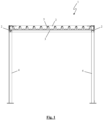
- the covering (1) illustrated in Fig. 1 comprises posts (4) to be able to place the covering (1) on the ground.
- therre are four posts (4) which support four beams (2) which have been assembled to form a frame.
- two single beams (2) to be provided instead of four beams (2), or three beams (2) which have been arranged in a triangle with respect to each other.
- a screen (3) is tensioned, in all directions, as is indicated by the arrows in Fig. 13 .
- This screen (3) forms a ceiling for the covering (1).
- steel deck (5) is arranged between these beams (2) which ensures that the beams (2) do not bend when tensioning the screen (3).
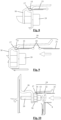
- At least one beam (2) of the covering (1) is provided with a gutter (6), as can be seen more clearly in Figs. 2 to 8 with two different illustrated embodiments.
- This gutter (6) is provided for draining off the precipitation falling on the covering.
- this gutter (6) extends under a side edge (7, 7', 7", 7"') of the screen (3).
- a side wall (8) of the gutter (6) is arranged under this screen (3).
- the screen (3) is a substantially rectangular screen (3) which is attached on each of its side edges (7, 7', 7", 7′′′) to the beams (2) by means of mounting profiles (16), tightening screws (19) and tensioning brackets (18).
- the screen (3) is provided with a half zip (15) on each of its side edges (7, 7', 7", 7′′′), which half zip may be held in a corresponding fitting slot (17) in a corresponding mounting profile (16).
- the mounting profiles (16) are attached to the beams (2) of the covering (1) by means of tensioning brackets (18) and tightening screws (19). By means of these tightening screws (19), the screen (3) can be tensioned on four sides.
- the screen (3) is in each case attachable and tensionable to the corresponding beam (2) just above the gutter (6) by means of the tightening screws (19).
- the tightening screws (19) are screwed to the tensioning brackets (18) above this gutter (6) and the tensioning brackets (18) are in turn attached to the beams (2) above this gutter (6).
- the corresponding mounting profile (16) is displaced to above the gutter (6) until the side wall (8) of the gutter (6) is arranged under the screen (3).
- a flexible sealing element (9) is attached at the bottom of the screen (3).
- the tightening screws (19) are not yet tightened up against the tensioning brackets (18)
- a hand tool can engage on the tightening screws (19) in order to screw the tightening screws (19) towards the tensioning brackets (18) and, if desired, tighten them against these tensioning brackets (18).
- the sealing element (9) is also displaced towards the gutter (6).
- this flexible sealing element (9) may then, in the tensioned position of the screen (3), be moved across the side wall (8) of the gutter (6) in order thus to close off the opening between the side wall (8) of the gutter (6) and the screen (3), so that insects can no longer penetrate into the space under the covering (1) via this opening.
- the screen (3) comprises a rectangular base screen (21) and four detachable mounting strips (20).
- Each mounting strip (20) is detachably attachable to a side edge (7, 7', 7", 7′′′) of the base screen (21) by means of a zip (22).
- each side edge (7, 7', 7", 7′′′) of the base screen (21) is provided with a half zip which may be made, for example, of polyester or nylon.
- this half zip may be welded, for example, to the base screen (21) with a weld seam.
- Each mounting strip (20) is provided with a corresponding half zip on both its longitudinal sides. This mounting strip (20) may then be coupled to the half zip of the corresponding side edge (7, 7', 7", 7′′′) of the base screen (21) by means of one of these half zips.
- the other one of the two half zips (15) may be used to attach the mounting strip (20) to the mounting profile (16), as has been described above and as is illustrated in Fig. 4 , this in order to attach the screen (3) to this mounting profile (16).
- the mounting profile (16) with a mounting strip (20) arranged thereon is first attached to the tensioning brackets (18) by means of tightening screws (19), without already tightening these tightening screws (19) onto the tensioning brackets (18), as can be seen in Figs. 4 and 8 .
- the base screen (21) is fixed to the mounting strip (20) by zipping, as can be seen in Figs. 5 and 9 .
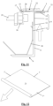
- the base screen (21) is initially rolled up, as can be seen in Fig. 12 , and is fixed on its clear side edge (7) by zipping onto the corresponding mounting strip (20) by means of the zip (22).
- the base screen (16) is attached on both sides (7', 7") simultaneously to the corresponding mounting strips (20) by means of the corresponding zips (22) while the base screen (21) is being unrolled, as is illustrated in Fig. 12 .
- the last side edge (7′′′) is then attached to the corresponding mounting strip (20) by means of the corresponding zip (22).
- the screen (3) is then fitted in the covering (1) in a tension-free manner.
- the tightening screws (19) are tightened, in which case the mounting profiles (16) are displaced towards the beams (2) in a direction perpendicular to the corresponding side edge (7, 7', 7", 7′′′) and in the plane of the screen (3). In this way, the screen (3) is tensioned.
- the tightening screws (19) may be engaged on by a hand tool in order to tension the screen (3), in this case via an opening which extends between the screen (3) and the side wall (8) of the gutter (6).
- the tightening screws (19) are screwed towards the tensioning brackets (18) and, if desired, tightened onto these tensioning brackets (18), as can be seen in Figs. 6 and 10 .
- the tightening screws (19) are tensionable in the covering (1), viewed on the underside of the screen (3).
- the zips (22) may preferably also be fixed to this underside by zipping.
- a sealing element (9) is arranged separately from the screen (3). Adjacent to the side wall (8) of the gutter (6), this sealing element (9) is slidable between a first position and a second position.
- this sealing element (9) substantially extends in the gutter (6), as can be seen is in Figs. 4 to 6 .
- the tightening screws (19) can be tightened through this opening.
- this sealing element (9) may be brought into the second position, in which it closes off the opening between the side wall (8) of the gutter (6) and the screen (3), as can be seen in Figs. 7 and 11 .
- the tensioning brackets (18), tightening screws (19) and the mounting strip (17) are then hidden from view by the sealing profile (9).
- the sealing element (9) also ensures that no insects can penetrate through the opening between the gutter (6) and the screen (3).
- the sealing element (9) is configured as a rigid sealing profile (9) which comprises a bearing part (11) which, in the second position, bears against the side wall (8) of the gutter (6) and a sealing part (13) which is arranged in a stepped manner with respect to the bearing part (11) and, in the second position, extends above the side wall (8) of the gutter (6) in order to close off the opening between the side wall (8) and the screen (3), as can be seen in Fig. 11 .
- This sealing element (9) is presses against the side wall (8) of the gutter (6) by means of leaf springs (10) which are arranged in the gutter (6). These leaf springs (10) allow a sliding movement of the sealing element (9) with respect to this side wall (8). IN this case, the sealing element (9) is then displaceable between its first position and its second position in a direction perpendicular to the screen (3).
- a flange (14) is provided at the top of the sealing part (13), which flange (14) extends at the top of the sealing element (9), away from the gutter (6) and perpendicular to the sealing part (13).
- This flange (14) may be engaged on at various locations in order to displace the sealing element (9) with respect to the side wall (8) of the gutter (6).
- the mounting strip (20) is pulled to above the gutter (6) when tightening the tightening screws (19), this mounting strip (20) is also hidden from view by the sealing element (9) when it is brought into its second position.
- the flange (14) also hides the zip (22) from view as well.
Landscapes
- Engineering & Computer Science (AREA)
- Architecture (AREA)
- Civil Engineering (AREA)
- Structural Engineering (AREA)
- Operating, Guiding And Securing Of Roll- Type Closing Members (AREA)
Claims (13)
- Abdeckung (1), umfassend zumindest zwei Träger (2) und einen zwischen diesen Trägern (2) angeordneten Screen (3), wobei zumindest ein Träger (2) mit einer Rinne (6) versehen ist, die sich unter einer Seitenkante (7, 7', 7'', 7‴) des Screens (3) erstreckt, wobei eine Seitenwand (8) dieser Rinne (6) in einem Abstand unter diesem Screen (3) angeordnet ist, wobei die Abdeckung (1) ein Dichtelement (9) umfasst, das zwischen einer ersten Position, in der eine freie Öffnung zwischen der Seitenwand (8) der Rinne (6) und dem Screen (3) oberhalb der Seitenwand (8) der Rinne (6) oder zwischen dem Dichtelement (9) und dem Screen (3) vorhanden ist, und einer zweiten Position, in der das Dichtelement (9) diese Öffnung zumindest teilweise verschließt, verschiebbar ist, wobei die Abdeckung (1) zumindest ein Montageprofil (16) umfasst, an dem der Screen (3) anbringbar oder angebracht ist und das zur Befestigung des Screens (3) an diesen Trägern (2) an einem Träger (2) anbringbar ist, und wobei diese Abdeckung (1) Spannmittel (19) umfasst, die an dem Montageprofil (16) in Eingriff kommen, um den Screen (3) bezüglich dieses Trägers (2) zu spannen, dadurch gekennzeichnet, dass die Spannmittel (19) in der ersten Position über die Öffnung spannbar sind.
- Abdeckung (1) nach Anspruch 1, dadurch gekennzeichnet, dass das Dichtelement (9) getrennt von dem Screen (3) angeordnet ist.
- Abdeckung (1) nach einem der vorhergehenden Ansprüche, dadurch gekennzeichnet, dass das Dichtelement (9) in einer senkrecht zu dem Screen (3) verlaufenden Richtung verschiebbar ist.
- Abdeckung (1) nach Anspruch 3, dadurch gekennzeichnet, dass das der Seitenwand (8) der Rinne (6) benachbarte Dichtelement (9) bezüglich dieser Seitenwand (8) verschiebbar angeordnet ist.
- Abdeckung (1) nach Anspruch 4, dadurch gekennzeichnet, dass die Abdeckung (1) ein oder mehrere federnde Elemente (10) umfasst, um das Dichtelement (9) gegen diese Seitenwand (8) zu drücken.
- Abdeckung (1) nach Anspruch 5, dadurch gekennzeichnet, dass die federnden Elemente (10) als Blattfedern (10) ausgestaltet sind.
- Abdeckung (1) nach einem der vorhergehenden Ansprüche, dadurch gekennzeichnet, dass das Dichtelement (9) ein Eingriffselement (14) umfasst, das zum Verschieben des Dichtelements (9) in Eingriff bringbar ist.
- Abdeckung (1) nach Anspruch 7, dadurch gekennzeichnet, dass das Eingriffselement (14) als ein Flansch (14) ausgestaltet ist.
- Abdeckung (1) nach einem der vorhergehenden Ansprüche, dadurch gekennzeichnet, dass das Dichtelement (9) ein Lagerteil (11) umfasst, das in der zweiten Position an der Seitenwand (8) der Rinne (6) anliegt und ein bezüglich des Lagerteils (11) gestuft angeordnetes Dichtungsteil (13) umfasst, wobei sich dieses Dichtungsteil (13) in der zweiten Position über der Seitenwand (8) der Rinne (6) erstreckt, um die Öffnung zwischen der Seitenwand (8) und dem Screen (3) zu verschließen.
- Abdeckung (1) nach den Ansprüchen 8 und 9, dadurch gekennzeichnet, dass sich der Flansch (14) oben an dem Dichtungsteil (13) von der Rinne (6) weg und senkrecht zu diesem Dichtungsteil (13) erstreckt.
- Abdeckung (1) nach einem der vorhergehenden Ansprüche, dadurch gekennzeichnet, dass sich das Dichtelement (9) zumindest in der ersten Position zumindest teilweise in der Rinne (6) erstreckt.
- Abdeckung (1) nach einem der vorhergehenden Ansprüche, dadurch gekennzeichnet, dass der Screen (6) einen Basis-Screen (21) und eine Montageleiste (20) umfasst, die an dem Montageprofil (16) anbringbar oder angebracht ist, um den Screen (3) an dem Montageprofil (16) zu befestigen, und die an dem Basis-Screen (21) anbringbar ist.
- Abdeckung (1) nach Anspruch 12, dadurch gekennzeichnet, dass das Dichtelement (9) in der Einbauposition Sichtschutz für die Montageleiste (20) in der zweiten Position bietet.
Applications Claiming Priority (2)
| Application Number | Priority Date | Filing Date | Title |
|---|---|---|---|
| BE2018/0007A BE1025900B1 (nl) | 2018-01-15 | 2018-01-15 | Doekspansysteem en werkwijze voor het bevestigen van een opgespannen doek |
| BE2018/0008A BE1025907B1 (nl) | 2018-01-15 | 2018-01-15 | Overkapping |
Publications (3)
| Publication Number | Publication Date |
|---|---|
| EP3511489A1 EP3511489A1 (de) | 2019-07-17 |
| EP3511489C0 EP3511489C0 (de) | 2025-03-05 |
| EP3511489B1 true EP3511489B1 (de) | 2025-03-05 |
Family
ID=65440755
Family Applications (1)
| Application Number | Title | Priority Date | Filing Date |
|---|---|---|---|
| EP19151876.0A Active EP3511489B1 (de) | 2018-01-15 | 2019-01-15 | Abdeckung |
Country Status (1)
| Country | Link |
|---|---|
| EP (1) | EP3511489B1 (de) |
Families Citing this family (2)
| Publication number | Priority date | Publication date | Assignee | Title |
|---|---|---|---|---|
| IT201600112860A1 (it) * | 2016-11-09 | 2018-05-09 | Renson Sunprotection Screens Nv | Barriera o schermo di protezione |
| WO2024156275A1 (en) * | 2023-01-28 | 2024-08-02 | Zhejiang Zhengte Co., Ltd. | Carport pergola |
Citations (1)
| Publication number | Priority date | Publication date | Assignee | Title |
|---|---|---|---|---|
| EP2468976B1 (de) * | 2010-12-21 | 2015-11-25 | Airbus Operations GmbH | Verkleidung |
Family Cites Families (10)
| Publication number | Priority date | Publication date | Assignee | Title |
|---|---|---|---|---|
| FR2602539B1 (fr) | 1986-08-11 | 1989-06-09 | Hayashiguchi Seizo | Ecran de fenetre |
| NL1014061C2 (nl) | 2000-01-14 | 2001-07-17 | Hamstra Weesp B V | Rolhor. |
| GB0313587D0 (en) | 2003-06-12 | 2003-07-16 | Cooper Andrew P | Barrier |
| KR100820369B1 (ko) | 2007-08-30 | 2008-04-23 | 주식회사 캬라반이에스 | 장력보강수단이 구비된 막구조물 |
| BE1019068A5 (nl) | 2009-12-09 | 2012-02-07 | Kestelyn Nv | Schermconstructie met verbeterde waterafvoer. |
| NL1038427C2 (nl) | 2009-12-09 | 2012-12-28 | Kestelyn N V | Scherminrichting. |
| ITMI20111803A1 (it) | 2011-10-05 | 2013-04-06 | Frigerio Tende Da Sole S R L | Struttura di tenda orizzontale retrattile a pacchetto. |
| WO2014043779A1 (en) | 2012-09-19 | 2014-03-27 | Les Industries Harnois Inc. | Retaining membrane on a structure |
| DE202014008425U1 (de) * | 2014-10-23 | 2016-01-26 | Novavert Gmbh & Co. Kg | Wetterschutzmodul und Wetterschutzvorrichtung aus derartigen Wetterschutzmodulen |
| DE102016001390B3 (de) * | 2016-02-09 | 2017-07-06 | Michael Elmendorff | Wettersegel |
-
2019
- 2019-01-15 EP EP19151876.0A patent/EP3511489B1/de active Active
Patent Citations (1)
| Publication number | Priority date | Publication date | Assignee | Title |
|---|---|---|---|---|
| EP2468976B1 (de) * | 2010-12-21 | 2015-11-25 | Airbus Operations GmbH | Verkleidung |
Also Published As
| Publication number | Publication date |
|---|---|
| EP3511489C0 (de) | 2025-03-05 |
| EP3511489A1 (de) | 2019-07-17 |
Similar Documents
| Publication | Publication Date | Title |
|---|---|---|
| US4768317A (en) | Ultra-lite stationary awning structures | |
| CN100434652C (zh) | 张紧的防风暴用织物板 | |
| US5289662A (en) | Wall coping system | |
| US6904720B1 (en) | Construction enclosure system | |
| US5209029A (en) | Construction assembly for awnings | |
| EP0795068B1 (de) | Temporäre schutzverkleidung | |
| WO2007103692A2 (en) | Wind abatement barrier mounting brackets and kit | |
| US4192112A (en) | Pliable awning system | |
| US9920534B2 (en) | Integrated support system and canopy | |
| US6401426B1 (en) | Method of dispensing netting for a roof structure | |
| US5148640A (en) | Manageable awning system | |
| EP3511489A1 (de) | Abdeckung | |
| US20110225860A1 (en) | Copy Raising, Lowering and Tensioning System for a Billboard | |
| US8146709B2 (en) | Movable safety barrier system | |
| US6421980B1 (en) | Method of dispensing netting for a roof structure | |
| US5619827A (en) | Roof edge flashing and anchoring system | |
| US6363684B1 (en) | Method of dispensing netting for a roof structure | |
| RU2655863C1 (ru) | Строительный профильный элемент для крепления гибких полотнищ и узел фиксации гибких полотнищ к несущему элементу каркасной конструкции | |
| US6003282A (en) | Movable safety barrier for construction of a roof structure | |
| BE1025900B1 (nl) | Doekspansysteem en werkwijze voor het bevestigen van een opgespannen doek | |
| US12203272B1 (en) | Tarp support apparatus and system | |
| BE1025907B1 (nl) | Overkapping | |
| JPH05248083A (ja) | 特にぴんと張られた平織布地のための見えない継ぎ合わせの装置 | |
| EP2345772B1 (de) | Markise | |
| AU2019216605B2 (en) | Fall Arrest System |
Legal Events
| Date | Code | Title | Description |
|---|---|---|---|
| PUAI | Public reference made under article 153(3) epc to a published international application that has entered the european phase |
Free format text: ORIGINAL CODE: 0009012 |
|
| STAA | Information on the status of an ep patent application or granted ep patent |
Free format text: STATUS: THE APPLICATION HAS BEEN PUBLISHED |
|
| AK | Designated contracting states |
Kind code of ref document: A1 Designated state(s): AL AT BE BG CH CY CZ DE DK EE ES FI FR GB GR HR HU IE IS IT LI LT LU LV MC MK MT NL NO PL PT RO RS SE SI SK SM TR |
|
| AX | Request for extension of the european patent |
Extension state: BA ME |
|
| STAA | Information on the status of an ep patent application or granted ep patent |
Free format text: STATUS: REQUEST FOR EXAMINATION WAS MADE |
|
| 17P | Request for examination filed |
Effective date: 20191220 |
|
| RBV | Designated contracting states (corrected) |
Designated state(s): AL AT BE BG CH CY CZ DE DK EE ES FI FR GB GR HR HU IE IS IT LI LT LU LV MC MK MT NL NO PL PT RO RS SE SI SK SM TR |
|
| STAA | Information on the status of an ep patent application or granted ep patent |
Free format text: STATUS: EXAMINATION IS IN PROGRESS |
|
| 17Q | First examination report despatched |
Effective date: 20220512 |
|
| RAP3 | Party data changed (applicant data changed or rights of an application transferred) |
Owner name: RENSON OUTDOOR NV |
|
| GRAP | Despatch of communication of intention to grant a patent |
Free format text: ORIGINAL CODE: EPIDOSNIGR1 |
|
| STAA | Information on the status of an ep patent application or granted ep patent |
Free format text: STATUS: GRANT OF PATENT IS INTENDED |
|
| INTG | Intention to grant announced |
Effective date: 20241212 |
|
| GRAS | Grant fee paid |
Free format text: ORIGINAL CODE: EPIDOSNIGR3 |
|
| GRAA | (expected) grant |
Free format text: ORIGINAL CODE: 0009210 |
|
| STAA | Information on the status of an ep patent application or granted ep patent |
Free format text: STATUS: THE PATENT HAS BEEN GRANTED |
|
| AK | Designated contracting states |
Kind code of ref document: B1 Designated state(s): AL AT BE BG CH CY CZ DE DK EE ES FI FR GB GR HR HU IE IS IT LI LT LU LV MC MK MT NL NO PL PT RO RS SE SI SK SM TR |
|
| REG | Reference to a national code |
Ref country code: GB Ref legal event code: FG4D |
|
| REG | Reference to a national code |
Ref country code: CH Ref legal event code: EP |
|
| REG | Reference to a national code |
Ref country code: DE Ref legal event code: R096 Ref document number: 602019066738 Country of ref document: DE |
|
| REG | Reference to a national code |
Ref country code: IE Ref legal event code: FG4D |
|
| U01 | Request for unitary effect filed |
Effective date: 20250305 |
|
| U07 | Unitary effect registered |
Designated state(s): AT BE BG DE DK EE FI FR IT LT LU LV MT NL PT RO SE SI Effective date: 20250313 |
|
| PG25 | Lapsed in a contracting state [announced via postgrant information from national office to epo] |
Ref country code: RS Free format text: LAPSE BECAUSE OF FAILURE TO SUBMIT A TRANSLATION OF THE DESCRIPTION OR TO PAY THE FEE WITHIN THE PRESCRIBED TIME-LIMIT Effective date: 20250605 |
|
| PG25 | Lapsed in a contracting state [announced via postgrant information from national office to epo] |
Ref country code: ES Free format text: LAPSE BECAUSE OF FAILURE TO SUBMIT A TRANSLATION OF THE DESCRIPTION OR TO PAY THE FEE WITHIN THE PRESCRIBED TIME-LIMIT Effective date: 20250305 |
|
| PG25 | Lapsed in a contracting state [announced via postgrant information from national office to epo] |
Ref country code: NO Free format text: LAPSE BECAUSE OF FAILURE TO SUBMIT A TRANSLATION OF THE DESCRIPTION OR TO PAY THE FEE WITHIN THE PRESCRIBED TIME-LIMIT Effective date: 20250605 |
|
| PG25 | Lapsed in a contracting state [announced via postgrant information from national office to epo] |
Ref country code: HR Free format text: LAPSE BECAUSE OF FAILURE TO SUBMIT A TRANSLATION OF THE DESCRIPTION OR TO PAY THE FEE WITHIN THE PRESCRIBED TIME-LIMIT Effective date: 20250305 |
|
| PG25 | Lapsed in a contracting state [announced via postgrant information from national office to epo] |
Ref country code: GR Free format text: LAPSE BECAUSE OF FAILURE TO SUBMIT A TRANSLATION OF THE DESCRIPTION OR TO PAY THE FEE WITHIN THE PRESCRIBED TIME-LIMIT Effective date: 20250606 |
|
| PG25 | Lapsed in a contracting state [announced via postgrant information from national office to epo] |
Ref country code: SM Free format text: LAPSE BECAUSE OF FAILURE TO SUBMIT A TRANSLATION OF THE DESCRIPTION OR TO PAY THE FEE WITHIN THE PRESCRIBED TIME-LIMIT Effective date: 20250305 |
|
| PG25 | Lapsed in a contracting state [announced via postgrant information from national office to epo] |
Ref country code: PL Free format text: LAPSE BECAUSE OF FAILURE TO SUBMIT A TRANSLATION OF THE DESCRIPTION OR TO PAY THE FEE WITHIN THE PRESCRIBED TIME-LIMIT Effective date: 20250305 |
|
| PG25 | Lapsed in a contracting state [announced via postgrant information from national office to epo] |
Ref country code: CZ Free format text: LAPSE BECAUSE OF FAILURE TO SUBMIT A TRANSLATION OF THE DESCRIPTION OR TO PAY THE FEE WITHIN THE PRESCRIBED TIME-LIMIT Effective date: 20250305 |
|
| PG25 | Lapsed in a contracting state [announced via postgrant information from national office to epo] |
Ref country code: SK Free format text: LAPSE BECAUSE OF FAILURE TO SUBMIT A TRANSLATION OF THE DESCRIPTION OR TO PAY THE FEE WITHIN THE PRESCRIBED TIME-LIMIT Effective date: 20250305 |
|
| PG25 | Lapsed in a contracting state [announced via postgrant information from national office to epo] |
Ref country code: IS Free format text: LAPSE BECAUSE OF FAILURE TO SUBMIT A TRANSLATION OF THE DESCRIPTION OR TO PAY THE FEE WITHIN THE PRESCRIBED TIME-LIMIT Effective date: 20250705 |
|
| PLBE | No opposition filed within time limit |
Free format text: ORIGINAL CODE: 0009261 |
|
| STAA | Information on the status of an ep patent application or granted ep patent |
Free format text: STATUS: NO OPPOSITION FILED WITHIN TIME LIMIT |
|
| REG | Reference to a national code |
Ref country code: CH Ref legal event code: L10 Free format text: ST27 STATUS EVENT CODE: U-0-0-L10-L00 (AS PROVIDED BY THE NATIONAL OFFICE) Effective date: 20260114 |
|
| REG | Reference to a national code |
Ref country code: CH Ref legal event code: U11 Free format text: ST27 STATUS EVENT CODE: U-0-0-U10-U11 (AS PROVIDED BY THE NATIONAL OFFICE) Effective date: 20260201 |
|
| 26N | No opposition filed |
Effective date: 20251208 |
|
| U20 | Renewal fee for the european patent with unitary effect paid |
Year of fee payment: 8 Effective date: 20260129 |
|
| PGFP | Annual fee paid to national office [announced via postgrant information from national office to epo] |
Ref country code: CH Payment date: 20260201 Year of fee payment: 8 |