EP3511472B1 - Baumaschine, insbesondere erdbewegungsmaschine mit einem bedienpult - Google Patents
Baumaschine, insbesondere erdbewegungsmaschine mit einem bedienpult Download PDFInfo
- Publication number
- EP3511472B1 EP3511472B1 EP18208306.3A EP18208306A EP3511472B1 EP 3511472 B1 EP3511472 B1 EP 3511472B1 EP 18208306 A EP18208306 A EP 18208306A EP 3511472 B1 EP3511472 B1 EP 3511472B1
- Authority
- EP
- European Patent Office
- Prior art keywords
- machine
- construction machine
- control unit
- mode
- operating
- Prior art date
- Legal status (The legal status is an assumption and is not a legal conclusion. Google has not performed a legal analysis and makes no representation as to the accuracy of the status listed.)
- Active
Links
Images


Classifications
-
- G—PHYSICS
- G05—CONTROLLING; REGULATING
- G05D—SYSTEMS FOR CONTROLLING OR REGULATING NON-ELECTRIC VARIABLES
- G05D1/00—Control of position, course, altitude or attitude of land, water, air or space vehicles, e.g. using automatic pilots
- G05D1/0011—Control of position, course, altitude or attitude of land, water, air or space vehicles, e.g. using automatic pilots associated with a remote control arrangement
- G05D1/0016—Control of position, course, altitude or attitude of land, water, air or space vehicles, e.g. using automatic pilots associated with a remote control arrangement characterised by the operator's input device
-
- B—PERFORMING OPERATIONS; TRANSPORTING
- B66—HOISTING; LIFTING; HAULING
- B66C—CRANES; LOAD-ENGAGING ELEMENTS OR DEVICES FOR CRANES, CAPSTANS, WINCHES, OR TACKLES
- B66C13/00—Other constructional features or details
- B66C13/16—Applications of indicating, registering, or weighing devices
-
- E—FIXED CONSTRUCTIONS
- E02—HYDRAULIC ENGINEERING; FOUNDATIONS; SOIL SHIFTING
- E02F—DREDGING; SOIL-SHIFTING
- E02F9/00—Component parts of dredgers or soil-shifting machines, not restricted to one of the kinds covered by groups E02F3/00 - E02F7/00
- E02F9/20—Drives; Control devices
-
- E—FIXED CONSTRUCTIONS
- E02—HYDRAULIC ENGINEERING; FOUNDATIONS; SOIL SHIFTING
- E02F—DREDGING; SOIL-SHIFTING
- E02F9/00—Component parts of dredgers or soil-shifting machines, not restricted to one of the kinds covered by groups E02F3/00 - E02F7/00
- E02F9/20—Drives; Control devices
- E02F9/2004—Control mechanisms, e.g. control levers
- E02F9/2012—Setting the functions of the control levers, e.g. changing assigned functions among operations levers, setting functions dependent on the operator or seat orientation
-
- E—FIXED CONSTRUCTIONS
- E02—HYDRAULIC ENGINEERING; FOUNDATIONS; SOIL SHIFTING
- E02F—DREDGING; SOIL-SHIFTING
- E02F9/00—Component parts of dredgers or soil-shifting machines, not restricted to one of the kinds covered by groups E02F3/00 - E02F7/00
- E02F9/20—Drives; Control devices
- E02F9/2025—Particular purposes of control systems not otherwise provided for
- E02F9/2033—Limiting the movement of frames or implements, e.g. to avoid collision between implements and the cabin
-
- E—FIXED CONSTRUCTIONS
- E02—HYDRAULIC ENGINEERING; FOUNDATIONS; SOIL SHIFTING
- E02F—DREDGING; SOIL-SHIFTING
- E02F9/00—Component parts of dredgers or soil-shifting machines, not restricted to one of the kinds covered by groups E02F3/00 - E02F7/00
- E02F9/20—Drives; Control devices
- E02F9/2025—Particular purposes of control systems not otherwise provided for
- E02F9/205—Remotely operated machines, e.g. unmanned vehicles
-
- E—FIXED CONSTRUCTIONS
- E02—HYDRAULIC ENGINEERING; FOUNDATIONS; SOIL SHIFTING
- E02F—DREDGING; SOIL-SHIFTING
- E02F9/00—Component parts of dredgers or soil-shifting machines, not restricted to one of the kinds covered by groups E02F3/00 - E02F7/00
- E02F9/26—Indicating devices
-
- E—FIXED CONSTRUCTIONS
- E02—HYDRAULIC ENGINEERING; FOUNDATIONS; SOIL SHIFTING
- E02F—DREDGING; SOIL-SHIFTING
- E02F9/00—Component parts of dredgers or soil-shifting machines, not restricted to one of the kinds covered by groups E02F3/00 - E02F7/00
- E02F9/26—Indicating devices
- E02F9/267—Diagnosing or detecting failure of vehicles
-
- G—PHYSICS
- G05—CONTROLLING; REGULATING
- G05D—SYSTEMS FOR CONTROLLING OR REGULATING NON-ELECTRIC VARIABLES
- G05D1/00—Control of position, course, altitude or attitude of land, water, air or space vehicles, e.g. using automatic pilots
- G05D1/0011—Control of position, course, altitude or attitude of land, water, air or space vehicles, e.g. using automatic pilots associated with a remote control arrangement
- G05D1/0044—Control of position, course, altitude or attitude of land, water, air or space vehicles, e.g. using automatic pilots associated with a remote control arrangement by providing the operator with a computer generated representation of the environment of the vehicle, e.g. virtual reality, maps
-
- G—PHYSICS
- G06—COMPUTING OR CALCULATING; COUNTING
- G06F—ELECTRIC DIGITAL DATA PROCESSING
- G06F1/00—Details not covered by groups G06F3/00 - G06F13/00 and G06F21/00
- G06F1/16—Constructional details or arrangements
- G06F1/1613—Constructional details or arrangements for portable computers
- G06F1/163—Wearable computers, e.g. on a belt
-
- G—PHYSICS
- G06—COMPUTING OR CALCULATING; COUNTING
- G06F—ELECTRIC DIGITAL DATA PROCESSING
- G06F21/00—Security arrangements for protecting computers, components thereof, programs or data against unauthorised activity
- G06F21/30—Authentication, i.e. establishing the identity or authorisation of security principals
- G06F21/31—User authentication
-
- H—ELECTRICITY
- H04—ELECTRIC COMMUNICATION TECHNIQUE
- H04N—PICTORIAL COMMUNICATION, e.g. TELEVISION
- H04N7/00—Television systems
- H04N7/18—Closed-circuit television [CCTV] systems, i.e. systems in which the video signal is not broadcast
Definitions
- the invention relates to a construction machine, in particular an earthmoving machine with a control panel.
- buttons/switches are usually designed as membrane keypads or finger-operated switches.
- the control elements are printed with defined symbols or provided with appropriate labels in the immediate vicinity of the control element. Feedback after pressing the individual control elements is provided only in the form of light effects.
- the inventors recognized the problem described above and set themselves the task of developing a novel concept for a control panel for controlling a construction machine that overcomes the aforementioned problems. This problem is solved by a construction machine having the features of claim 1. Advantageous embodiments of the construction machine are the subject of the dependent claims.
- a construction machine in particular an earthmoving machine, particularly preferably an excavator, for example in the form of a hydraulic excavator, with at least one control panel for inputting operator commands for controlling the construction machine.
- the core of the invention is the equipping of the control panel with at least one display means that displays a dynamically generated user interface for machine control.
- a control unit is also provided for controlling this display means, which detects a change in the operating mode of the construction machine and adapts the user interface accordingly depending on the change in operating mode.
- This design solution therefore offers the possibility of providing a compact control panel that dynamically generates a corresponding user interface for controlling the machine depending on the device mode, i.e. depending on the work processes to be carried out.
- the generated user interface is preferably a graphical user interface, in particular with one or more graphical operating symbols, e.g., in the form of switches, buttons, or other operating elements, and/or with switch or button labels.
- the operator is therefore dynamically offered a limited selection of functions or control commands adapted to the respective operating mode. Therefore, before the actual generation of the user interface, the control unit determines which functions and control commands are permitted or even useful for the respective operating mode.
- control elements that have no relevant function for the current device mode or work process are either specially marked, hidden or not displayed at all to optimise the clarity of the control panel.
- the display of the control panel is a touch-sensitive display element.
- the operating elements represented by the user interface are therefore activated by touching the respective position on the display.
- the touch display can be a multi-touch display.
- control panel comprises one or more real control elements, the labeling of which can be changed by means of the display means and consequently also their function assignment by the control unit.
- the control panel may further comprise at least one information display element that does not output any control elements, but is intended solely for information output.
- this informative display element may also be part of the display means for displaying dynamic control elements.
- Information is also output via a graphical user interface that distributes one or more information fields in an orderly manner across the available display area.
- the control unit can also be configured to dynamically adapt or generate the user interface of the information display element depending on the detected device mode. Here, too, only information fields relevant to the respective device mode can be displayed.
- the operating mode of the construction machine is understood to be, for example, regular work operation, for example, in the case of an excavator, regular excavator operation.
- Another operating mode can be the driving mode of the construction machine, allowing it to be moved not only on the construction site but also in road traffic.
- the operating mode can be understood to be maintenance or test operation.
- control panel's display element displays the corresponding controls for regular excavation operations via the control panel's display element while the machine is in "Working Mode" and to make them available for function call-up.
- information display element If the operator then switches to driving mode, the control panel's display element displays the corresponding controls for moving the construction machine around the construction site or in traffic, and the information display element displays driving information, such as the current speed, navigation data, etc.
- This approach has the advantage that the operator quickly receives a clear display of the available controls in the respective device mode.
- the invention also reduces the risk of operating errors, since the controls not required in the respective device mode and the corresponding Functions are hidden and therefore not available for selection or operation.
- the dynamic generation of the user interface i.e., the display of any operating elements or the pure information display
- the control unit can also detect changes in the machine status and dynamically adapt the user interface depending on the detected changes in status.
- One possible status could, for example, be the corresponding equipment of the construction machine. In the case of an excavator, this could mean the installation of the corresponding attachment.
- the appropriate operating elements for controlling the attachment are then displayed on the control panel.
- the control unit can detect a completed tool change on the construction machine and subsequently adapt the user interface of the display. The same can be the case with the semi-automated calling of a tool check or a lighting control.
- a device or machine condition that triggers an adjustment of the user interface could, for example, be a deviation between the target and actual values of any control loop of the construction machine.
- An example of this would be the corresponding climate control system in the construction machine cabin. If the control unit detects a deviation between the target interior temperature of the cabin and the actual interior temperature, the control unit can automatically display the corresponding controls for the climate control to alert the operator to this deviation and immediately offer them appropriate controls for adjustment.
- the control unit automatically or semi-automatically detects changes in the existing environmental conditions. Depending on the detected changes, the dynamically generated user interface of the display means or the information display element can then be adapted. It is conceivable that, depending on twilight, precipitation, or temperature values, appropriate controls can be displayed. Ideally, controls for controlling the construction machine's lighting can be displayed starting at a certain twilight level. Certain precipitation values trigger the display of controls for controlling a windshield wiper system, while controls for the driver's cab's air conditioning are displayed at corresponding outside temperatures.
- control unit can be configured to recognize specific manual user inputs and, in response, adapt the user interface of the display element accordingly.
- These specific user inputs are understood to be inputs that are not made via the user interface, but rather, for example, via an external fixed control element.
- this includes control inputs via master control elements, such as the sensors located next to the driver's seat.
- the displayed user interface or the representation on the information display element is automatically adapted to the process for actuating the support.
- the above section outlines a number of factors that are evaluated and considered by the control unit to subsequently dynamically generate a corresponding user interface. It can be advantageous to assign different weightings to these factors when adapting the user interface or the display on the information display element in order to control their influence on the respective adaptation. It makes sense for the control unit to assign a higher priority to a change in the operating mode than to the other influencing factors.
- both the display means of the control panel and any information display element provide customizable display areas. This allows the visual display to be adapted to the respective user needs. This can be done by storing user profiles in the control unit or an external, retrievable memory. Furthermore, it is advisable to equip the control unit or the construction machine with authentication tools that, after successful user authentication, automatically retrieve the assigned user profile and adapt the user interface and/or the display on the information display element according to the profile settings.
- a further aspect of the invention provides for actively supporting the user when switching between different operating modes.
- the presets to be checked and monitored include any machine settings and existing machine parameters, as well as specific position data or alignments of individual construction machine components.
- the control unit automatically checks the mode-relevant presets.
- a correction process can advantageously be triggered to adapt the detected presets.
- the correction process can either actively inform the user of the necessary correction of the respective preset, e.g. by means of a visual prompt and, ideally, appropriate display of the required operating elements, or the control unit can make the correction automatically and, if necessary, inform the user of the correction made.
- the control unit actively prompts the user to move the uppercarriage to the appropriate position. If the user follows this prompt, the control unit can then automatically lock the slewing gear, for example.
- the construction machine in particular the control unit, can be designed with at least one interface for communication with at least one mobile device.
- the interface serves for communication with so-called wearables.
- remote access to the user interface shown on the display device can be achieved using the linked mobile devices.
- the core idea of the invention is a dynamically generated user interface.
- a large portion of the function keys for controlling the construction machine, which would otherwise be implemented in hardware, are now simulated using a graphical user interface that displays the relevant control elements depending on the operating mode, machine status, and other influencing factors.
- the displayed control elements are limited to the functions relevant to the work process being performed, so that the entire control panel is not only clearer and easier to handle for the machine operator, since the reduced number of control elements can be placed in the most accessible location for the machine operator, but operational safety can also be increasingly improved, as the probability of unintentional incorrect inputs can be reduced.
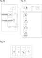
- the control panel comprises a display element in the form of a touch-sensitive display, which serves to display a graphical user interface. Furthermore, an information display is provided, which merely shows the machine data to the operator.
- the invention in particular the control unit, ensures that both the user interface on the touch display and the information display are adapted during operation depending on the work process and device status.
- Both the information display and the touchscreen for operation are positioned within the construction machine cab, making them easily visible to the operator.
- the touchscreen in particular, is ergonomically positioned for the operator.
- the information display and touchscreen can be designed separately or as a single, compact unit. A removable solution for both units is also conceivable.
- the information display and user interface of the touchscreen can be easily retrofitted and expanded with newly implemented functions (e.g., detecting a new attachment).
- both elements can provide customizable sections in both the display and the user interface, which can be designed and saved for different operators according to their personal preferences. In this case, it is useful for the operator to be entered or automatically recognized. Ideally, the personalized settings are recognized and made available across all devices.
- a special aspect of the invention is that the operation is structured and, according to certain priorities, only the operating and setting options relevant to the respective work process are made available.
- the control unit checks which device mode is currently active and whether a switchover between the respective device modes is desired.
- the selected device mode here Mode 1, 2, or 3
- the relevant functions for operating the construction machine in the respective mode are determined and grouped.
- the necessary requirements for the respective mode are checked. The latter will be discussed later with reference to the Figures 2 or 3 explained in detail.
- an operating mode can include regular work mode (e.g., digging mode on an excavator).
- the corresponding controls are displayed on the touch display of the control panel.
- a screenshot of a possible representation of the user interface is shown in Figure 4a Each box can be selected by touch, and the associated function can be called up. Appropriate symbols make the associated functions self-explanatory.
- a second mode could be road driving, for example. After selecting the mode, the touch display could then show the Figure 4b The exemplary user interface is displayed. A clear difference can be seen in the number of control elements and their assigned functions.
- the control unit can query whether other influencing factors exist that affect the dynamic generation of the user interface or the information display.
- trigger factors include maintenance, operation, or the environment.
- the former is detected by an operator requesting maintenance, e.g., by pressing a corresponding switch or connecting a maintenance device to a designated interface. If a maintenance request is received, the user interface is immediately adapted to the maintenance task by displaying the necessary controls for performing maintenance work.
- control unit continues to check for specific operator inputs. This includes, for example, the operation of a master control element, such as a gripper to control individual actuators of the construction machine, in particular, activation of the excavation system, or generally the invocation of new work orders. If the check is positive, the appropriate user interface is generated immediately. An example of the resulting user interface or the representation on the information display is in Figure 4c This is displayed immediately when the excavator operator operates a master control element for controlling the excavator support.
- a master control element such as a gripper to control individual actuators of the construction machine, in particular, activation of the excavation system, or generally the invocation of new work orders.
- control unit cannot detect the corresponding inputs, the presence of relevant environmental influences is checked and, if necessary, the user interface is adjusted. These include, for example, the ambient brightness conditions detected by sensors, the current precipitation, as well as the ambient temperature or the temperature inside the machine cabin. If necessary, the user interface can be supplemented with controls for lighting, windshield wipers, or the climate control within the cabin.
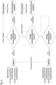
- Figure 2 shows the process for checking any device dependencies during a mode change.
- the control unit detects that the user intends to change the device mode from Mode A to Mode B.
- the control unit checks any device settings, device alignments, or device parameters to see whether they meet the requirements for changing to Device Mode B.
- the check begins with Device Dependency A. If the assigned value A does not meet the requirements for a mode change, the machine operator is informed and actively prompted to correct it, preferably by immediately displaying the appropriate control elements. After successful driver interaction, the next Device Dependency B is checked in a similar way and, if necessary, corrected. Once all device dependencies are met, the mode change can be completed and the user interface can be adapted to the new mode.
- FIG. 3 A concrete example of such a mode change in an excavator is shown in Figure 3 shown.
- the excavator is to be switched from "Work" mode to "Road” mode.
- "Work” mode there are mode-specific settings.
- the servo circuit must be switched on, an automatic oscillating axle must be active, and the corresponding display on the control panel must be adjusted to "Work" mode (see, for example, Figure 1).
- Figure 4a If a corresponding request to change mode is detected, the control unit first checks the alignment of the uppercarriage, in particular whether the rotation position of the uppercarriage meets the requirements for road travel.
- the operator is prompted accordingly (see Figure 4e ), to align the uppercarriage to the undercarriage accordingly.
- the control unit continuously checks whether the excavator operator is executing the appropriate operating commands, i.e., operating the servo control to align the uppercarriage. Once the uppercarriage alignment requirement has been met, the slewing gear brake can be automatically locked by the control unit.
- the control unit checks the next machine status, namely, querying the alignment of the equipment or attachment. If the equipment or attachment is correctly aligned for road travel, or if the operator has aligned it by actuating it accordingly following a prompt from the control unit, the control unit can lock the servo control and then query whether the operator has fastened their seat belt for road travel. If this can also be answered positively, the excavator is finally switched to road travel mode, and the corresponding user interface is generated on the display element of the control panel ( Figure 4b ).
- Certain individual functions can also be operated in conjunction with each other. For example, after parking and activating the parking brake, the ambient and access lighting are also activated, the equipment is depressurized, etc.
- control holograms can indicate different operating scopes and work processes. See illustrations 4f and 4g for examples.
- a pure on/off function for example, is represented by a rectangular hologram with chamfered edges ( Figure 4f ).
- Round control elements can contain additional setting options in addition to the activation/deactivation function ( Figure 4f ).
- a short press activates/deactivates the assigned function
- a long press calls up a submenu or substructure.
- an elongated, rectangular shape of the control element can indicate an underlying logic, such as the automatic detection of the onset of dusk ( Figure 4g ).
- the assigned function can be executed automatically or a notification is simply given about a necessary setting change.
- All control elements are, where necessary, implemented with understandable status visualizations.
- schematic device representations are used to present warnings, information, and functionality in a simpler and more understandable way.
- the status of the respective function can be displayed directly via a display of the control element, for example, using animated frame (see Figure 4g ), use of different colors, additions with symbols (see e.g. lock symbol or arrows in Figure 4d )
- mobile devices such as wearables can also be used for the people involved in the operating process.
- the wearables can be permanently linked to the construction machine via a contactless interface, e.g., Wi-Fi device hotspots.
- the construction machine can detect the position of the wearables and thus of the people involved in the immediate vicinity of the work equipment, thus enabling early detection of impending collisions with people while the work equipment is being moved.
- the positions of the construction site personnel can be displayed to the occupant in the cab, for example, via a top view of the equipment with superimposed person icons.
- the wearables also serve as a communication interface between all persons involved at the workplace. Limited access to equipment operation can be provided via the wearable if necessary, such as triggering an emergency stop in a hazardous situation (e.g., a person monitoring the digging process and detecting a collision with a ground wire).
- the wearable is designed to automatically pair with the nearest work tool, with different functionalities available depending on the tool.
Landscapes
- Engineering & Computer Science (AREA)
- General Engineering & Computer Science (AREA)
- Mining & Mineral Resources (AREA)
- Civil Engineering (AREA)
- Structural Engineering (AREA)
- Physics & Mathematics (AREA)
- Theoretical Computer Science (AREA)
- General Physics & Mathematics (AREA)
- Radar, Positioning & Navigation (AREA)
- Computer Hardware Design (AREA)
- Remote Sensing (AREA)
- Automation & Control Theory (AREA)
- Computer Security & Cryptography (AREA)
- Aviation & Aerospace Engineering (AREA)
- Software Systems (AREA)
- Mathematical Physics (AREA)
- Human Computer Interaction (AREA)
- Computing Systems (AREA)
- Mechanical Engineering (AREA)
- Multimedia (AREA)
- Signal Processing (AREA)
- Component Parts Of Construction Machinery (AREA)
- Operation Control Of Excavators (AREA)
Applications Claiming Priority (1)
| Application Number | Priority Date | Filing Date | Title |
|---|---|---|---|
| DE102017131264.1A DE102017131264A1 (de) | 2017-12-22 | 2017-12-22 | Baumaschine, insbesondere Erdbewegungsmaschine mit einem Bedienpult |
Publications (3)
| Publication Number | Publication Date |
|---|---|
| EP3511472A2 EP3511472A2 (de) | 2019-07-17 |
| EP3511472A3 EP3511472A3 (de) | 2019-12-04 |
| EP3511472B1 true EP3511472B1 (de) | 2025-05-07 |
Family
ID=64477017
Family Applications (1)
| Application Number | Title | Priority Date | Filing Date |
|---|---|---|---|
| EP18208306.3A Active EP3511472B1 (de) | 2017-12-22 | 2018-11-26 | Baumaschine, insbesondere erdbewegungsmaschine mit einem bedienpult |
Country Status (8)
| Country | Link |
|---|---|
| US (1) | US10996667B2 (pl) |
| EP (1) | EP3511472B1 (pl) |
| CN (1) | CN109958160B (pl) |
| DE (1) | DE102017131264A1 (pl) |
| DK (1) | DK3511472T3 (pl) |
| ES (1) | ES3034823T3 (pl) |
| FI (1) | FI3511472T3 (pl) |
| PL (1) | PL3511472T3 (pl) |
Cited By (1)
| Publication number | Priority date | Publication date | Assignee | Title |
|---|---|---|---|---|
| US20240083462A1 (en) * | 2020-10-23 | 2024-03-14 | Tusimple, Inc. | Safe driving operations of autonomous vehicles |
Families Citing this family (5)
| Publication number | Priority date | Publication date | Assignee | Title |
|---|---|---|---|---|
| US10723226B1 (en) * | 2019-01-15 | 2020-07-28 | Deere & Company | Machine control using biometric recognition |
| US11505919B2 (en) | 2020-07-27 | 2022-11-22 | Caterpillar Inc. | Method for remote operation of machines using a mobile device |
| CN113152550B (zh) * | 2021-04-07 | 2022-12-20 | 柳州柳工挖掘机有限公司 | 操作模式控制系统及方法和挖掘机 |
| DE102021128470B4 (de) * | 2021-11-02 | 2024-02-29 | GRAF-SYTECO GmbH & Co.KG | Bedienkonsole |
| EP4279664B1 (en) * | 2022-05-16 | 2024-08-21 | Hiab AB | Manoeuvring arrangement and a method for the manoeuvring arrangement |
Family Cites Families (20)
| Publication number | Priority date | Publication date | Assignee | Title |
|---|---|---|---|---|
| US5854988A (en) * | 1996-06-05 | 1998-12-29 | Topcon Laser Systems, Inc. | Method for controlling an excavator |
| JP2002317472A (ja) * | 2001-04-23 | 2002-10-31 | Komatsu Ltd | 作業車両のモニター装置 |
| DE10155006B4 (de) * | 2001-11-06 | 2004-12-16 | Terex-Demag Gmbh & Co. Kg | Fahrzeugkran mit Superlifteinrichtung |
| DE20207722U1 (de) | 2002-05-16 | 2003-09-18 | Liebherr-Werk Ehingen Gmbh, 89584 Ehingen | Bedienvorrichtung |
| DE602006006821D1 (de) * | 2005-05-27 | 2009-06-25 | Charles Machine Works | Bestimmung der position eines fernbedienungsanwenders |
| CN101113987A (zh) * | 2006-07-28 | 2008-01-30 | 刘绘夫 | 一种交通工具行驶速度的显示方法 |
| US20080082345A1 (en) * | 2006-09-29 | 2008-04-03 | Caterpillar Inc. | System and method for evaluating risks associated with delaying machine maintenance |
| US7937162B2 (en) * | 2006-10-31 | 2011-05-03 | Caterpillar Inc. | Machine operator interface having linked help feature |
| GB2461910B (en) * | 2008-07-17 | 2012-07-18 | Bamford Excavators Ltd | Method of operating an apparatus |
| JP5226734B2 (ja) * | 2010-05-20 | 2013-07-03 | 株式会社小松製作所 | ハイブリッド建設機械 |
| EP2573039A3 (en) * | 2011-09-23 | 2013-06-26 | Manitowoc Crane Companies, LLC | Outrigger monitoring system and methods |
| DE102012014655A1 (de) | 2012-07-24 | 2014-03-06 | Bomag Gmbh | Bedieneinheit für eine Baumaschine und Verfahren zum Betreiben der Bedieneinheit |
| DE102012111253A1 (de) * | 2012-09-27 | 2014-05-15 | Claas Selbstfahrende Erntemaschinen Gmbh | Verfahren zum Betreiben einer landwirtschaftlichen Arbeitsmaschine |
| JP6073170B2 (ja) * | 2013-03-27 | 2017-02-01 | 住友建機株式会社 | ショベル |
| US9547417B2 (en) * | 2013-03-29 | 2017-01-17 | Deere & Company | Retracting shortcut bars, status shortcuts and edit run page sets |
| CN103615850B (zh) * | 2013-12-04 | 2016-08-24 | 合肥美的电冰箱有限公司 | 冰箱 |
| US20160063332A1 (en) * | 2014-08-27 | 2016-03-03 | Toyota Jidosha Kabushiki Kaisha | Communication of external sourced information to a driver |
| US10006782B2 (en) * | 2014-11-12 | 2018-06-26 | Moj.Io Inc. | Characterization of sensor data for vehicle telematics |
| US9704398B2 (en) * | 2015-09-14 | 2017-07-11 | At&T Intellectual Property I, L.P. | Method and apparatus for enhancing driver situational awareness |
| DE102016012786A1 (de) * | 2016-10-26 | 2018-04-26 | Liebherr-Werk Biberach Gmbh | Fernsteuer-Einrichtung für Kran, Baumaschine und/oder Flurförderzeug |
-
2017
- 2017-12-22 DE DE102017131264.1A patent/DE102017131264A1/de active Pending
-
2018
- 2018-11-26 DK DK18208306.3T patent/DK3511472T3/da active
- 2018-11-26 FI FIEP18208306.3T patent/FI3511472T3/fi active
- 2018-11-26 PL PL18208306.3T patent/PL3511472T3/pl unknown
- 2018-11-26 EP EP18208306.3A patent/EP3511472B1/de active Active
- 2018-11-26 ES ES18208306T patent/ES3034823T3/es active Active
- 2018-12-20 US US16/227,526 patent/US10996667B2/en active Active
- 2018-12-21 CN CN201811569712.XA patent/CN109958160B/zh active Active
Cited By (1)
| Publication number | Priority date | Publication date | Assignee | Title |
|---|---|---|---|---|
| US20240083462A1 (en) * | 2020-10-23 | 2024-03-14 | Tusimple, Inc. | Safe driving operations of autonomous vehicles |
Also Published As
| Publication number | Publication date |
|---|---|
| US20190196462A1 (en) | 2019-06-27 |
| RU2018145319A3 (pl) | 2022-04-06 |
| EP3511472A3 (de) | 2019-12-04 |
| DK3511472T3 (da) | 2025-06-02 |
| CN109958160B (zh) | 2022-05-10 |
| PL3511472T3 (pl) | 2025-11-03 |
| US10996667B2 (en) | 2021-05-04 |
| DE102017131264A1 (de) | 2019-06-27 |
| EP3511472A2 (de) | 2019-07-17 |
| RU2018145319A (ru) | 2020-06-22 |
| CN109958160A (zh) | 2019-07-02 |
| ES3034823T3 (en) | 2025-08-25 |
| FI3511472T3 (fi) | 2025-06-30 |
Similar Documents
| Publication | Publication Date | Title |
|---|---|---|
| EP3511472B1 (de) | Baumaschine, insbesondere erdbewegungsmaschine mit einem bedienpult | |
| EP3099618B1 (de) | Kransteuerung | |
| DE112016000013B4 (de) | Steuersystem für ein Arbeitsfahrzeug, Steuerverfahren und Arbeitsfahrzeug | |
| EP2139803B1 (de) | Verfahren zum steuern einer lastbewegungsvorrichtung und steuerung einer lastbewegungsvorrichtung | |
| EP3041779B1 (de) | Arbeitsmaschine und verfahren zu deren betrieb | |
| DE102018208500B4 (de) | Bedienvorrichtung für eine Baumaschine | |
| DE102014012550A1 (de) | Kraftfahrzeug-Bedienungsvorrichtung | |
| EP2889253B1 (de) | Flurförderzeug mit Anzeige- und Bedienvorrichtung | |
| EP3713867B1 (de) | Kran mit anti-kollisions-einrichtung sowie verfahren zum betreiben mehrerer solcher krane | |
| EP3435140A1 (de) | Arbeitsmaschine mit anzeigeeinrichtung | |
| EP3010745B1 (de) | Kraftfahrzeug | |
| DE102016205797A1 (de) | Verfahren und Vorrichtung zum Zuordnen von Steuerbefehlen in einem Fahrzeug sowie Fahrzeug | |
| EP2896027B1 (de) | Verfahren zum bedienen eines fernsteuerungssystems | |
| DE112013001041T5 (de) | Anzeigesteuerungseinrichtung für Baumaschine | |
| DE102013100419A1 (de) | Flurförderzeug mit Komfortfunktion | |
| DE102011101714A1 (de) | Verfahren einer elektrohydraulischen Hubwerksregelung und Bedieneinheit für eine elektrohydraulische Hubwerksregelung | |
| DE102022200153A1 (de) | Verfahren zum Unterstützen eines Anwenders mit einem Indikator | |
| EP2889258B9 (de) | Flurförderzeug mit einer Anzeige- und Bedienvorrichtung | |
| EP2844804B1 (de) | Baumaschinensteuerung | |
| DE102017219649A1 (de) | Vorrichtung und Verfahren zur Steuerung einer Arbeitsmaschine | |
| EP3667470A1 (de) | Verfahren zum bereitstellen einer benutzerschnittstelle und benutzerschnittstelle eines fahrzeugs | |
| RU2781962C2 (ru) | Строительная машина, в частности землеройно-транспортная машина с пультом обслуживания | |
| DE102014209078B4 (de) | Verfahren und Vorrichtung zum Bedienen eines Fahrerassistenzsystems | |
| DE102013011414A1 (de) | Verfahren und Vorrichtung zum Steuern von Spiegelfunktionen in einem Fahrzeug sowie betreffendes Computerprogrammprodukt | |
| DE19506641A1 (de) | Steuerpult für eine Baumaschine |
Legal Events
| Date | Code | Title | Description |
|---|---|---|---|
| PUAI | Public reference made under article 153(3) epc to a published international application that has entered the european phase |
Free format text: ORIGINAL CODE: 0009012 |
|
| STAA | Information on the status of an ep patent application or granted ep patent |
Free format text: STATUS: THE APPLICATION HAS BEEN PUBLISHED |
|
| AK | Designated contracting states |
Kind code of ref document: A2 Designated state(s): AL AT BE BG CH CY CZ DE DK EE ES FI FR GB GR HR HU IE IS IT LI LT LU LV MC MK MT NL NO PL PT RO RS SE SI SK SM TR |
|
| AX | Request for extension of the european patent |
Extension state: BA ME |
|
| PUAL | Search report despatched |
Free format text: ORIGINAL CODE: 0009013 |
|
| AK | Designated contracting states |
Kind code of ref document: A3 Designated state(s): AL AT BE BG CH CY CZ DE DK EE ES FI FR GB GR HR HU IE IS IT LI LT LU LV MC MK MT NL NO PL PT RO RS SE SI SK SM TR |
|
| AX | Request for extension of the european patent |
Extension state: BA ME |
|
| RIC1 | Information provided on ipc code assigned before grant |
Ipc: H04N 7/18 20060101ALI20191030BHEP Ipc: B66C 13/16 20060101ALI20191030BHEP Ipc: E02F 9/26 20060101ALI20191030BHEP Ipc: E02F 9/20 20060101AFI20191030BHEP |
|
| STAA | Information on the status of an ep patent application or granted ep patent |
Free format text: STATUS: REQUEST FOR EXAMINATION WAS MADE |
|
| 17P | Request for examination filed |
Effective date: 20200604 |
|
| TPAC | Observations filed by third parties |
Free format text: ORIGINAL CODE: EPIDOSNTIPA |
|
| TPAC | Observations filed by third parties |
Free format text: ORIGINAL CODE: EPIDOSNTIPA |
|
| STAA | Information on the status of an ep patent application or granted ep patent |
Free format text: STATUS: EXAMINATION IS IN PROGRESS |
|
| 17Q | First examination report despatched |
Effective date: 20230622 |
|
| GRAP | Despatch of communication of intention to grant a patent |
Free format text: ORIGINAL CODE: EPIDOSNIGR1 |
|
| STAA | Information on the status of an ep patent application or granted ep patent |
Free format text: STATUS: GRANT OF PATENT IS INTENDED |
|
| INTG | Intention to grant announced |
Effective date: 20250113 |
|
| GRAS | Grant fee paid |
Free format text: ORIGINAL CODE: EPIDOSNIGR3 |
|
| GRAA | (expected) grant |
Free format text: ORIGINAL CODE: 0009210 |
|
| STAA | Information on the status of an ep patent application or granted ep patent |
Free format text: STATUS: THE PATENT HAS BEEN GRANTED |
|
| AK | Designated contracting states |
Kind code of ref document: B1 Designated state(s): AL AT BE BG CH CY CZ DE DK EE ES FI FR GB GR HR HU IE IS IT LI LT LU LV MC MK MT NL NO PL PT RO RS SE SI SK SM TR |
|
| P01 | Opt-out of the competence of the unified patent court (upc) registered |
Free format text: CASE NUMBER: APP_14948/2025 Effective date: 20250327 |
|
| REG | Reference to a national code |
Ref country code: GB Ref legal event code: FG4D Free format text: NOT ENGLISH |
|
| REG | Reference to a national code |
Ref country code: CH Ref legal event code: EP |
|
| REG | Reference to a national code |
Ref country code: DE Ref legal event code: R096 Ref document number: 502018015788 Country of ref document: DE |
|
| REG | Reference to a national code |
Ref country code: DK Ref legal event code: T3 Effective date: 20250526 |
|
| REG | Reference to a national code |
Ref country code: IE Ref legal event code: FG4D Free format text: LANGUAGE OF EP DOCUMENT: GERMAN |
|
| REG | Reference to a national code |
Ref country code: FI Ref legal event code: FGE |
|
| REG | Reference to a national code |
Ref country code: NL Ref legal event code: FP |
|
| REG | Reference to a national code |
Ref country code: ES Ref legal event code: FG2A Ref document number: 3034823 Country of ref document: ES Kind code of ref document: T3 Effective date: 20250825 |
|
| REG | Reference to a national code |
Ref country code: SE Ref legal event code: TRGR |
|
| PG25 | Lapsed in a contracting state [announced via postgrant information from national office to epo] |
Ref country code: PT Free format text: LAPSE BECAUSE OF FAILURE TO SUBMIT A TRANSLATION OF THE DESCRIPTION OR TO PAY THE FEE WITHIN THE PRESCRIBED TIME-LIMIT Effective date: 20250908 |
|
| REG | Reference to a national code |
Ref country code: LT Ref legal event code: MG9D |
|
| PG25 | Lapsed in a contracting state [announced via postgrant information from national office to epo] |
Ref country code: GR Free format text: LAPSE BECAUSE OF FAILURE TO SUBMIT A TRANSLATION OF THE DESCRIPTION OR TO PAY THE FEE WITHIN THE PRESCRIBED TIME-LIMIT Effective date: 20250808 |
|
| PG25 | Lapsed in a contracting state [announced via postgrant information from national office to epo] |
Ref country code: BG Free format text: LAPSE BECAUSE OF FAILURE TO SUBMIT A TRANSLATION OF THE DESCRIPTION OR TO PAY THE FEE WITHIN THE PRESCRIBED TIME-LIMIT Effective date: 20250507 |
|
| PG25 | Lapsed in a contracting state [announced via postgrant information from national office to epo] |
Ref country code: HR Free format text: LAPSE BECAUSE OF FAILURE TO SUBMIT A TRANSLATION OF THE DESCRIPTION OR TO PAY THE FEE WITHIN THE PRESCRIBED TIME-LIMIT Effective date: 20250507 |
|
| PG25 | Lapsed in a contracting state [announced via postgrant information from national office to epo] |
Ref country code: RS Free format text: LAPSE BECAUSE OF FAILURE TO SUBMIT A TRANSLATION OF THE DESCRIPTION OR TO PAY THE FEE WITHIN THE PRESCRIBED TIME-LIMIT Effective date: 20250807 |
|
| PG25 | Lapsed in a contracting state [announced via postgrant information from national office to epo] |
Ref country code: IS Free format text: LAPSE BECAUSE OF FAILURE TO SUBMIT A TRANSLATION OF THE DESCRIPTION OR TO PAY THE FEE WITHIN THE PRESCRIBED TIME-LIMIT Effective date: 20250907 |
|
| PG25 | Lapsed in a contracting state [announced via postgrant information from national office to epo] |
Ref country code: LV Free format text: LAPSE BECAUSE OF FAILURE TO SUBMIT A TRANSLATION OF THE DESCRIPTION OR TO PAY THE FEE WITHIN THE PRESCRIBED TIME-LIMIT Effective date: 20250507 |
|
| REG | Reference to a national code |
Ref country code: CH Ref legal event code: U11 Free format text: ST27 STATUS EVENT CODE: U-0-0-U10-U11 (AS PROVIDED BY THE NATIONAL OFFICE) Effective date: 20251201 |