EP3511150B1 - Method for manufacturing complex shaped product using one or more jigs and mandrels - Google Patents
Method for manufacturing complex shaped product using one or more jigs and mandrels Download PDFInfo
- Publication number
- EP3511150B1 EP3511150B1 EP16899691.6A EP16899691A EP3511150B1 EP 3511150 B1 EP3511150 B1 EP 3511150B1 EP 16899691 A EP16899691 A EP 16899691A EP 3511150 B1 EP3511150 B1 EP 3511150B1
- Authority
- EP
- European Patent Office
- Prior art keywords
- mandrel
- product
- stacking surface
- manufacturing
- jig
- Prior art date
- Legal status (The legal status is an assumption and is not a legal conclusion. Google has not performed a legal analysis and makes no representation as to the accuracy of the status listed.)
- Active
Links
Images







Classifications
-
- B—PERFORMING OPERATIONS; TRANSPORTING
- B29—WORKING OF PLASTICS; WORKING OF SUBSTANCES IN A PLASTIC STATE IN GENERAL
- B29C—SHAPING OR JOINING OF PLASTICS; SHAPING OF MATERIAL IN A PLASTIC STATE, NOT OTHERWISE PROVIDED FOR; AFTER-TREATMENT OF THE SHAPED PRODUCTS, e.g. REPAIRING
- B29C53/00—Shaping by bending, folding, twisting, straightening or flattening; Apparatus therefor
- B29C53/80—Component parts, details or accessories; Auxiliary operations
- B29C53/82—Cores or mandrels
- B29C53/821—Mandrels especially adapted for winding and joining
- B29C53/828—Arrangements comprising a plurality of cores or mandrels, e.g. to increase production speed
-
- A—HUMAN NECESSITIES
- A01—AGRICULTURE; FORESTRY; ANIMAL HUSBANDRY; HUNTING; TRAPPING; FISHING
- A01K—ANIMAL HUSBANDRY; AVICULTURE; APICULTURE; PISCICULTURE; FISHING; REARING OR BREEDING ANIMALS, NOT OTHERWISE PROVIDED FOR; NEW BREEDS OF ANIMALS
- A01K87/00—Fishing rods
- A01K87/04—Fishing-line guides on rods, e.g. tips
-
- B—PERFORMING OPERATIONS; TRANSPORTING
- B29—WORKING OF PLASTICS; WORKING OF SUBSTANCES IN A PLASTIC STATE IN GENERAL
- B29C—SHAPING OR JOINING OF PLASTICS; SHAPING OF MATERIAL IN A PLASTIC STATE, NOT OTHERWISE PROVIDED FOR; AFTER-TREATMENT OF THE SHAPED PRODUCTS, e.g. REPAIRING
- B29C53/00—Shaping by bending, folding, twisting, straightening or flattening; Apparatus therefor
- B29C53/80—Component parts, details or accessories; Auxiliary operations
- B29C53/82—Cores or mandrels
-
- B—PERFORMING OPERATIONS; TRANSPORTING
- B29—WORKING OF PLASTICS; WORKING OF SUBSTANCES IN A PLASTIC STATE IN GENERAL
- B29C—SHAPING OR JOINING OF PLASTICS; SHAPING OF MATERIAL IN A PLASTIC STATE, NOT OTHERWISE PROVIDED FOR; AFTER-TREATMENT OF THE SHAPED PRODUCTS, e.g. REPAIRING
- B29C70/00—Shaping composites, i.e. plastics material comprising reinforcements, fillers or preformed parts, e.g. inserts
- B29C70/04—Shaping composites, i.e. plastics material comprising reinforcements, fillers or preformed parts, e.g. inserts comprising reinforcements only, e.g. self-reinforcing plastics
- B29C70/28—Shaping operations therefor
- B29C70/40—Shaping or impregnating by compression not applied
- B29C70/42—Shaping or impregnating by compression not applied for producing articles of definite length, i.e. discrete articles
- B29C70/46—Shaping or impregnating by compression not applied for producing articles of definite length, i.e. discrete articles using matched moulds, e.g. for deforming sheet moulding compounds [SMC] or prepregs
-
- B—PERFORMING OPERATIONS; TRANSPORTING
- B29—WORKING OF PLASTICS; WORKING OF SUBSTANCES IN A PLASTIC STATE IN GENERAL
- B29C—SHAPING OR JOINING OF PLASTICS; SHAPING OF MATERIAL IN A PLASTIC STATE, NOT OTHERWISE PROVIDED FOR; AFTER-TREATMENT OF THE SHAPED PRODUCTS, e.g. REPAIRING
- B29C53/00—Shaping by bending, folding, twisting, straightening or flattening; Apparatus therefor
- B29C53/36—Bending and joining, e.g. for making hollow articles
- B29C53/38—Bending and joining, e.g. for making hollow articles by bending sheets or strips at right angles to the longitudinal axis of the article being formed and joining the edges
-
- B—PERFORMING OPERATIONS; TRANSPORTING
- B29—WORKING OF PLASTICS; WORKING OF SUBSTANCES IN A PLASTIC STATE IN GENERAL
- B29C—SHAPING OR JOINING OF PLASTICS; SHAPING OF MATERIAL IN A PLASTIC STATE, NOT OTHERWISE PROVIDED FOR; AFTER-TREATMENT OF THE SHAPED PRODUCTS, e.g. REPAIRING
- B29C53/00—Shaping by bending, folding, twisting, straightening or flattening; Apparatus therefor
- B29C53/36—Bending and joining, e.g. for making hollow articles
- B29C53/38—Bending and joining, e.g. for making hollow articles by bending sheets or strips at right angles to the longitudinal axis of the article being formed and joining the edges
- B29C53/40—Bending and joining, e.g. for making hollow articles by bending sheets or strips at right angles to the longitudinal axis of the article being formed and joining the edges for articles of definite length, i.e. discrete articles
- B29C53/42—Bending and joining, e.g. for making hollow articles by bending sheets or strips at right angles to the longitudinal axis of the article being formed and joining the edges for articles of definite length, i.e. discrete articles using internal forming surfaces, e.g. mandrels
-
- B—PERFORMING OPERATIONS; TRANSPORTING
- B29—WORKING OF PLASTICS; WORKING OF SUBSTANCES IN A PLASTIC STATE IN GENERAL
- B29C—SHAPING OR JOINING OF PLASTICS; SHAPING OF MATERIAL IN A PLASTIC STATE, NOT OTHERWISE PROVIDED FOR; AFTER-TREATMENT OF THE SHAPED PRODUCTS, e.g. REPAIRING
- B29C53/00—Shaping by bending, folding, twisting, straightening or flattening; Apparatus therefor
- B29C53/56—Winding and joining, e.g. winding spirally
-
- B—PERFORMING OPERATIONS; TRANSPORTING
- B29—WORKING OF PLASTICS; WORKING OF SUBSTANCES IN A PLASTIC STATE IN GENERAL
- B29C—SHAPING OR JOINING OF PLASTICS; SHAPING OF MATERIAL IN A PLASTIC STATE, NOT OTHERWISE PROVIDED FOR; AFTER-TREATMENT OF THE SHAPED PRODUCTS, e.g. REPAIRING
- B29C53/00—Shaping by bending, folding, twisting, straightening or flattening; Apparatus therefor
- B29C53/80—Component parts, details or accessories; Auxiliary operations
- B29C53/84—Heating or cooling
-
- B—PERFORMING OPERATIONS; TRANSPORTING
- B29—WORKING OF PLASTICS; WORKING OF SUBSTANCES IN A PLASTIC STATE IN GENERAL
- B29C—SHAPING OR JOINING OF PLASTICS; SHAPING OF MATERIAL IN A PLASTIC STATE, NOT OTHERWISE PROVIDED FOR; AFTER-TREATMENT OF THE SHAPED PRODUCTS, e.g. REPAIRING
- B29C70/00—Shaping composites, i.e. plastics material comprising reinforcements, fillers or preformed parts, e.g. inserts
- B29C70/04—Shaping composites, i.e. plastics material comprising reinforcements, fillers or preformed parts, e.g. inserts comprising reinforcements only, e.g. self-reinforcing plastics
- B29C70/28—Shaping operations therefor
- B29C70/30—Shaping by lay-up, i.e. applying fibres, tape or broadsheet on a mould, former or core; Shaping by spray-up, i.e. spraying of fibres on a mould, former or core
-
- B—PERFORMING OPERATIONS; TRANSPORTING
- B29—WORKING OF PLASTICS; WORKING OF SUBSTANCES IN A PLASTIC STATE IN GENERAL
- B29K—INDEXING SCHEME ASSOCIATED WITH SUBCLASSES B29B, B29C OR B29D, RELATING TO MOULDING MATERIALS OR TO MATERIALS FOR MOULDS, REINFORCEMENTS, FILLERS OR PREFORMED PARTS, e.g. INSERTS
- B29K2105/00—Condition, form or state of moulded material or of the material to be shaped
- B29K2105/06—Condition, form or state of moulded material or of the material to be shaped containing reinforcements, fillers or inserts
- B29K2105/08—Condition, form or state of moulded material or of the material to be shaped containing reinforcements, fillers or inserts of continuous length, e.g. cords, rovings, mats, fabrics, strands or yarns
- B29K2105/0872—Prepregs
-
- B—PERFORMING OPERATIONS; TRANSPORTING
- B29—WORKING OF PLASTICS; WORKING OF SUBSTANCES IN A PLASTIC STATE IN GENERAL
- B29L—INDEXING SCHEME ASSOCIATED WITH SUBCLASS B29C, RELATING TO PARTICULAR ARTICLES
- B29L2031/00—Other particular articles
- B29L2031/52—Sports equipment ; Games; Articles for amusement; Toys
- B29L2031/5227—Clubs
-
- B—PERFORMING OPERATIONS; TRANSPORTING
- B29—WORKING OF PLASTICS; WORKING OF SUBSTANCES IN A PLASTIC STATE IN GENERAL
- B29L—INDEXING SCHEME ASSOCIATED WITH SUBCLASS B29C, RELATING TO PARTICULAR ARTICLES
- B29L2031/00—Other particular articles
- B29L2031/70—Agricultural usage or equipment
- B29L2031/7002—Agricultural usage or equipment for fishing
Definitions
- the present invention relates to a method of manufacturing a product having a complex shape by using at least one jig and at least one mandrel, and more specifically to a method of manufacturing a product having a complex shape by using at least one jig and at least one mandrel, which is capable of manufacturing a product having a complex shape by using a plurality of jigs and mandrels.
- a manufacturing method using a prepreg is used to manufacture strong and robust products, such as a fishing rod guide, a golf club, a fishing rod body, a ski pole, an alpenstock, an archery arrow shaft, a selfie stick, a tripod, a billiard cue, etc.
- JP 5 431285 B2 discloses that a fishing line guide includes a frame including a ring holding part into which the fishing line is inserted, a support leg part for separating the fishing line from the surface of the fishing rod, and an attaching part; and a fixed cylinder part which is slidable relative to the fishing rod R1 and which can be locked at a prescribed position to be integrated with the attaching part. Further, fiber-reinforced synthetic resin with reinforcing fibers oriented in at least three different directions is disposed in at least one region among the ring holding part, the support leg part, and the region where the attaching part is integrated with the fixed cylinder.
- JP H01 304931 A discloses that a prepreg sheet impregnated with a synthetic resin is wound around a respective mandrel. After that, these mandrels are gathered and arranged in parallel by placing these prepreg sheets to be adjacent to one another. Next, an outside sheet is wound around these outer periphery, and the prepreg sheets and the outside sheet are backed in this state. After that, a desired porous tubular member is obtained by extracting the mandrels by means of jigs or the like. Thereby, obtaining a porous tubular member in an easy production and with high strength.
- a hollow composite plastic structure contains a hollow, integrally molded plastic body with an outer frame wall which delimits an interior space and has two opposite open ends, and at least one separating web which defines the interior space of the outer frame wall divides into at least two cavities, each of which opens at the open ends of the outer frame wall.
- the molded plastic body contains a plurality of stacked first reinforcing fabric layers which are embedded in the outer frame wall and the separating web. Each of the first reinforcing fabric layers is wound around the corresponding one of the cavities.
- the molded plastic body further contains a plurality of stacked second reinforcing fabric layers which are embedded in the outer frame wall. Each of the second reinforcement fabric layers is wound around the cavities.
- the present invention has been conceived to overcome the above-described problem of the conventional art, and an object of the present invention is to provide a method of manufacturing a product having a complex shape by using at least one jig and at least one mandrel, which is capable of manufacturing a product having a complex shape by manufacturing a prepreg sheet by using a plurality of jigs and mandrels.
- Another object of the present invention is to provide a method of manufacturing a product having a complex shape by using at least one jig and at least one mandrel, which is capable of manufacturing a strong and robust product because the product is manufactured using at least one jig and at least one mandrel and thus the product is formed in a complex shape but in an integrated shape.
- a method of manufacturing a product having a complex shape by using at least one jig and at least one mandrel according to the present invention is configured to include: a preparation step of preparing a prepreg sheet and a cylindrical first mandrel around which the prepreg sheet is wound; a first rolling step of forming a first stacking surface by winding the prepreg sheet around the first mandrel; a second mandrel preparation step of locating a second mandrel on the outer circumferential surface of the first stacking surface; a second rolling step of forming a second stacking surface by winding the first stacking surface and the second mandrel with the prepreg sheet; and a core removal step of removing the first mandrel and the second mandrel.
- the present invention has been conceived to overcome the above-described problem of the conventional art, and there is provided the method of manufacturing a product having a complex shape by using at least one jig and at least one mandrel, which is capable of manufacturing a product having a complex shape by manufacturing a prepreg sheet by using a plurality of jigs and mandrels.
- the method of manufacturing a product having a complex shape by using at least one jig and at least one mandrel which is capable of manufacturing a strong and robust product because the product is manufactured using at least one jig and at least one mandrel and thus the product is formed in a complex shape but in an integrated shape.
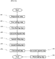
- a method of manufacturing a product having a complex shape by using at least one jig and at least one mandrel according to the present invention may be configured to include a preparation step 110, a first rolling step 120, a first heating step 130, a second mandrel preparation step 140, a second rolling step 150, a second heating step 160, and a core removal step 170.
- the preparation step 110 is the step of preparing a prepreg sheet 10 and a cylindrical first mandrel 20 around which the prepreg sheet 10 is wound, as shown in FIG. 1 .
- the prepreg sheet 10 is made of a material which is shaped using a method of stacking, and heating or pressing a material, and is provided in the shape of a sheet made of carbon or the like.
- the first rolling step 120 is the step of forming a first stacking surface 40 by winding the prepreg sheet 10 around the first mandrel 20, as shown in FIG. 2 .
- a method of winding the prepreg sheet 10 may include a method of rotating the first mandrel 20 after an end of the prepreg sheet 10 has been attached to the first mandrel 20, and a method of fastening the first mandrel 20 and winding the prepreg sheet 10 around the first mandrel 20.
- the first heating step 130 is the step of taping and heating the first stacking surface 40 after the first rolling step 120 has been performed.
- the prepreg sheet 10 is fastened not to be unwound by taping the first stacking surface 40, and the prepreg sheet 10 is combined by heating the first stacking surface 40 constituting the first stacking surface 40.
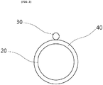
- the second mandrel preparation step 140 is the step of locating the second mandrel 30 at one point of the outer circumferential surface of the first stacking surface 40, as shown in FIG. 3 .
- the second mandrel 30 is preferably formed in a cylindrical shape, and the size thereof is preferably smaller than that of the first mandrel 20.
- the second mandrel 30 may be formed in various shapes.
- the second mandrel 30 may be provided as a jig having one of various non-cylindrical shapes, such as a triangular shape, a rectangular shape, a lozenge shape, etc.
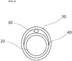
- the second rolling step 150 is the step of forming a second stacking surface 50 by winding the first stacking surface 40 and the second mandrel 30 with the prepreg sheet 10, as shown in FIG. 4 .
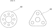
- a more complex product may be manufactured by installing a plurality of second mandrels 30, as shown in FIG. 7 .
- the second heating step 160 is the step of taping and heating the second stacking surface 50 after the second rolling step 150 has been performed.
- a combined stacking surface 60 is formed by combining the first stacking surface 40 and the second stacking surface 50 by heating the second stacking surface 50, and a hole formed between the first stacking surface 40 and the second stacking surface 50 is filled up. Since the prepreg sheet 10 is made of the material having the property of expanding with heat, the hole is filled up.
- the core removal step 170 is the step of removing the first mandrel 20 and the second mandrel 30 after the first stacking surface 40 and the second stacking surface 50 have been combined at the second heating step 160, as shown in FIG. 5 .
- the first mandrel 20 and second mandrel 30 are removed by the core removal step 170, and only the prepreg sheet 10 remains in the form of a product having a complex shape.
- the product formed by this step is machined, it may be used as a top guide of a fishing rod, as shown in FIG. 6 .
- a hole formed by the second mandrel 30 is a portion into which the fishing rod is inserted, and thus the top guide may be easily installed and used on the fishing rod.
- a third mandrel preparation step 180 and a third heating step 190 may be included after the core removal step 170 has been performed.
- the third mandrel preparation step 180 is the step of locating a third mandrel 80 on the outer circumferential surface of the second stacking surface 50, as shown in FIG. 9 .
- the third mandrel 80 may be formed in various shapes.
- the third heating step 190 is the step of taping and heating the second stacking surface 50 and the third mandrel 80.
- a depression attributable to the pressing action of the third mandrel 80 is formed on the outer circumferential surface of the second stacking surface 50 by applying heat onto the second stacking surface 50.
- FIG. 10 The shape of a product obtained after the third heating step 190 has been performed is shown in FIG. 10 .
- the product of FIG. 10 may be finally machined, may be used as a strip guide of a fishing rod, as shown in FIG. 11 , and may be easily attached or installed on the fishing rod.
- a method of manufacturing a product having a complex shape by using at least one jig and at least one mandrel according to a second embodiment may be configured to include a preparation step 210, a first rolling step 220, a second mandrel preparation step 230, a pressing step 240, a heating step 250, and a core removal step 260.
- the preparation step 210 is the step of preparing a prepreg sheet 10 and a cylindrical first mandrel 20 around which the prepreg sheet 10 is wound.
- the first rolling step 220 is the step of forming a first stacking surface 40 by winding the prepreg sheet 10 around the first mandrel 20.
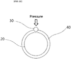
- the second mandrel preparation step 230 is the step of locating a second mandrel 30 on the outer circumferential surface of the first stacking surface 40, as shown in FIG. 12 .
- the pressing step 240 is the step of taping the first stacking surface 40 and the second mandrel 30, as shown in FIG. 12 .
- the heating step 250 is the step of heating the first stacking surface 40 and the second mandrel 30.
- the core removal step 260 is the step of removing the first mandrel 20, the second mandrel 30, and tape.
- a product completed by performing the core removal step 260 is shown in FIG. 13a .
- the product of FIG. 13a may be formed into a one-neck guide of a fishing rod after separate machining, as shown in FIG. 13b .
- a depression formed by the second mandrel 30 enables the one-neck guide to be easily installed on the fishing rod.
- the method of manufacturing a product having a complex shape by using at least one jig and at least one mandrel according to the second embodiment is basically the same in a material used, steps, and the details of the steps as the method of manufacturing a product having a complex shape by using at least one jig and at least one mandrel according to the first embodiment, but they are different in the sequence of the steps from each other.
- a plurality of depressions may be formed on the outer circumferential surface of the first stacking surface 40 by using a plurality of second mandrels 30. Due to the plurality of depressions, when a product is machined into a fishing rod, a golf club, or the like, a sound can be generated whenever the product is swung, and the strength of the product can be further enhanced.
Landscapes
- Engineering & Computer Science (AREA)
- Mechanical Engineering (AREA)
- Life Sciences & Earth Sciences (AREA)
- Chemical & Material Sciences (AREA)
- Composite Materials (AREA)
- Environmental Sciences (AREA)
- Marine Sciences & Fisheries (AREA)
- Animal Husbandry (AREA)
- Biodiversity & Conservation Biology (AREA)
- Fishing Rods (AREA)
- Moulding By Coating Moulds (AREA)
Description
- The present invention relates to a method of manufacturing a product having a complex shape by using at least one jig and at least one mandrel, and more specifically to a method of manufacturing a product having a complex shape by using at least one jig and at least one mandrel, which is capable of manufacturing a product having a complex shape by using a plurality of jigs and mandrels.
- Generally, a manufacturing method using a prepreg is used to manufacture strong and robust products, such as a fishing rod guide, a golf club, a fishing rod body, a ski pole, an alpenstock, an archery arrow shaft, a selfie stick, a tripod, a billiard cue, etc.
- However, conventional products using prepregs are chiefly used as products having simple shapes due to difficulties in the machining of prepreg materials. Accordingly, the conventional method has a problem in that it is difficult to manufacture a product having a complex shape.
-
JP 5 431285 B2 -
JP H01 304931 A -
DE 100 11 879 A1 discloses that a hollow composite plastic structure contains a hollow, integrally molded plastic body with an outer frame wall which delimits an interior space and has two opposite open ends, and at least one separating web which defines the interior space of the outer frame wall divides into at least two cavities, each of which opens at the open ends of the outer frame wall. The molded plastic body contains a plurality of stacked first reinforcing fabric layers which are embedded in the outer frame wall and the separating web. Each of the first reinforcing fabric layers is wound around the corresponding one of the cavities. The molded plastic body further contains a plurality of stacked second reinforcing fabric layers which are embedded in the outer frame wall. Each of the second reinforcement fabric layers is wound around the cavities. - The present invention has been conceived to overcome the above-described problem of the conventional art, and an object of the present invention is to provide a method of manufacturing a product having a complex shape by using at least one jig and at least one mandrel, which is capable of manufacturing a product having a complex shape by manufacturing a prepreg sheet by using a plurality of jigs and mandrels.
- Another object of the present invention is to provide a method of manufacturing a product having a complex shape by using at least one jig and at least one mandrel, which is capable of manufacturing a strong and robust product because the product is manufactured using at least one jig and at least one mandrel and thus the product is formed in a complex shape but in an integrated shape.
- The technical problems which the present invention is intended to overcome are not limited to those described above, and other technical problems which the present invention is intended to overcome will be clearly understood from the following description by those having ordinary knowledge in the art to which the present invention pertains.
- A method of manufacturing a product having a complex shape by using at least one jig and at least one mandrel according to the present invention is configured to include: a preparation step of preparing a prepreg sheet and a cylindrical first mandrel around which the prepreg sheet is wound; a first rolling step of forming a first stacking surface by winding the prepreg sheet around the first mandrel; a second mandrel preparation step of locating a second mandrel on the outer circumferential surface of the first stacking surface; a second rolling step of forming a second stacking surface by winding the first stacking surface and the second mandrel with the prepreg sheet; and a core removal step of removing the first mandrel and the second mandrel.
- According to an embodiment of the present invention, the present invention has been conceived to overcome the above-described problem of the conventional art, and there is provided the method of manufacturing a product having a complex shape by using at least one jig and at least one mandrel, which is capable of manufacturing a product having a complex shape by manufacturing a prepreg sheet by using a plurality of jigs and mandrels.
- Furthermore, there is provided the method of manufacturing a product having a complex shape by using at least one jig and at least one mandrel, which is capable of manufacturing a strong and robust product because the product is manufactured using at least one jig and at least one mandrel and thus the product is formed in a complex shape but in an integrated shape.
-
-
FIG. 1 is a view showing the preparation step of a method of manufacturing a product having a complex shape by using at least one jig and at least one mandrel according to a first embodiment of the present invention; -
FIG. 2 is a view showing the first rolling step of the method of manufacturing a product having a complex shape by using at least one jig and at least one mandrel according to the first embodiment of the present invention; -
FIG. 3 is a view showing the second mandrel preparation step of the method of manufacturing a product having a complex shape by using at least one jig and at least one mandrel according to the first embodiment of the present invention; -
FIG. 4 is a view showing the second rolling step of the method of manufacturing a product having a complex shape by using at least one jig and at least one mandrel according to the first embodiment of the present invention; -
FIG. 5 is a view showing the second heating step and core removal step of the method of manufacturing a product having a complex shape by using at least one jig and at least one mandrel according to the first embodiment of the present invention; -
FIG. 6 is a view showing a top guide of a fishing rod which is formed through separate machining after the core removal step of the method of manufacturing a product having a complex shape by using at least one jig and at least one mandrel according to the first embodiment of the present invention has been performed; -
FIG. 7 is a view showing products completed based on the numbers of mandrels in the method of manufacturing a product having a complex shape by using at least one jig and at least one mandrel according to the first embodiment of the present invention; -
FIG. 8 is a view showing a product completed using a jig instead of second mandrel in the method of manufacturing a product having a complex shape by using at least one jig and at least one mandrel according to the first embodiment of the present invention; -
FIG. 9 is a view showing the third mandrel preparation step of the method of manufacturing a product having a complex shape by using at least one jig and at least one mandrel according to the first embodiment of the present invention; -
FIG. 10 is a view showing the appearance of a product completed after the third heating step of the method of manufacturing a product having a complex shape by using at least one jig and at least one mandrel according to the first embodiment of the present invention has been performed, and also showing the appearance of a strip guide of a fishing rod formed through separate machining; -
FIG. 11 is a block diagram showing the manufacturing steps of the method of manufacturing a product having a complex shape by using at least one jig and at least one mandrel according to the first embodiment of the present invention; -
FIG. 12 is a view showing the second mandrel preparation step of a method of manufacturing a product having a complex shape by using at least one jig and at least one mandrel according to a second embodiment of the present invention; -
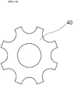
FIG. 13 is a view showing the appearance of a product completed using the method of manufacturing a product having a complex shape by using at least one jig and at least one mandrel according to the second embodiment of the present invention, and also showing the appearance of a one-neck guide of a fishing rod formed through separate machining; -
FIG. 14 is a view showing the appearance of a product completed using a plurality of second mandrels in the method of manufacturing a product having a complex shape by using at least one jig and at least one mandrel according to the second embodiment of the present invention; and -
FIG. 15 is a block diagram showing the manufacturing steps of the method of manufacturing a product having a complex shape by using at least one jig and at least one mandrel according to the second embodiment of the present invention. - 10:
- prepreg sheet
- 20:
- first mandrel
- 30:
- second mandrel
- 40:
- first stacking surface
- 50:
- second stacking surface
- 60:
- combined stacking surface
- 80:
- third mandrel
- 110:
- preparation step
- 120:
- first rolling step
- 130:
- first heating step
- 140:
- second mandrel preparation step
- 150:
- second rolling step
- 160:
- second heating step
- 170:
- core removal step
- 180:
- third mandrel preparation step
- 190:
- third heating step
- 210:
- preparation step
- 220:
- first rolling step
- 230:
- second mandrel preparation step
- 240:
- pressing step
- 250:
- heating step
- 260:
- core removal step
- Specific details including the technical problems, technical solution, and advantageous effects of the present invention are included in the following embodiments and the accompanying drawings. The advantages and features of the present invention and methods for achieving the advantages and the features will be apparent by reference to embodiments that will be described in detail below in conjunction with the accompanying drawings.
- The present invention will be described in detail below with reference to the accompanying drawings
- As shown in
FIGS. 1 to 11 , a method of manufacturing a product having a complex shape by using at least one jig and at least one mandrel according to the present invention may be configured to include apreparation step 110, afirst rolling step 120, afirst heating step 130, a secondmandrel preparation step 140, asecond rolling step 150, asecond heating step 160, and acore removal step 170. - First, the
preparation step 110 is the step of preparing aprepreg sheet 10 and a cylindricalfirst mandrel 20 around which theprepreg sheet 10 is wound, as shown inFIG. 1 . Theprepreg sheet 10 is made of a material which is shaped using a method of stacking, and heating or pressing a material, and is provided in the shape of a sheet made of carbon or the like. - Next, the
first rolling step 120 is the step of forming a first stackingsurface 40 by winding theprepreg sheet 10 around thefirst mandrel 20, as shown inFIG. 2 . A method of winding theprepreg sheet 10 may include a method of rotating thefirst mandrel 20 after an end of theprepreg sheet 10 has been attached to thefirst mandrel 20, and a method of fastening thefirst mandrel 20 and winding theprepreg sheet 10 around thefirst mandrel 20. - Next, the
first heating step 130 is the step of taping and heating the first stackingsurface 40 after thefirst rolling step 120 has been performed. At thefirst heating step 130, theprepreg sheet 10 is fastened not to be unwound by taping the first stackingsurface 40, and theprepreg sheet 10 is combined by heating the first stackingsurface 40 constituting the first stackingsurface 40. - Next, the second
mandrel preparation step 140 is the step of locating thesecond mandrel 30 at one point of the outer circumferential surface of the first stackingsurface 40, as shown inFIG. 3 . Thesecond mandrel 30 is preferably formed in a cylindrical shape, and the size thereof is preferably smaller than that of thefirst mandrel 20. Thesecond mandrel 30 may be formed in various shapes. In particular, thesecond mandrel 30 may be provided as a jig having one of various non-cylindrical shapes, such as a triangular shape, a rectangular shape, a lozenge shape, etc. - Next, the
second rolling step 150 is the step of forming a second stackingsurface 50 by winding the first stackingsurface 40 and thesecond mandrel 30 with theprepreg sheet 10, as shown inFIG. 4 . - When a product having a more complex shape is required, a more complex product may be manufactured by installing a plurality of
second mandrels 30, as shown inFIG. 7 . - Next, the
second heating step 160 is the step of taping and heating the second stackingsurface 50 after thesecond rolling step 150 has been performed. At thesecond heating step 160, a combined stackingsurface 60 is formed by combining the first stackingsurface 40 and the second stackingsurface 50 by heating the second stackingsurface 50, and a hole formed between the first stackingsurface 40 and the second stackingsurface 50 is filled up. Since theprepreg sheet 10 is made of the material having the property of expanding with heat, the hole is filled up. - Next, the
core removal step 170 is the step of removing thefirst mandrel 20 and thesecond mandrel 30 after the first stackingsurface 40 and the second stackingsurface 50 have been combined at thesecond heating step 160, as shown inFIG. 5 . Thefirst mandrel 20 andsecond mandrel 30 are removed by thecore removal step 170, and only theprepreg sheet 10 remains in the form of a product having a complex shape. When the product formed by this step is machined, it may be used as a top guide of a fishing rod, as shown inFIG. 6 . A hole formed by thesecond mandrel 30 is a portion into which the fishing rod is inserted, and thus the top guide may be easily installed and used on the fishing rod. - Next, as shown in
FIGS. 8 to 10 , when the jig is used instead of thesecond mandrel 30 at the secondmandrel preparation step 140, a thirdmandrel preparation step 180 and athird heating step 190 may be included after thecore removal step 170 has been performed. - The third
mandrel preparation step 180 is the step of locating athird mandrel 80 on the outer circumferential surface of the second stackingsurface 50, as shown inFIG. 9 . Thethird mandrel 80 may be formed in various shapes. - The
third heating step 190 is the step of taping and heating the second stackingsurface 50 and thethird mandrel 80. At thethird heating step 190, a depression attributable to the pressing action of thethird mandrel 80 is formed on the outer circumferential surface of the second stackingsurface 50 by applying heat onto the second stackingsurface 50. - After the
third heating step 190 has been performed, tape and thethird mandrel 80 are removed, and final machining into a desired shape is performed. The shape of a product obtained after thethird heating step 190 has been performed is shown inFIG. 10 . The product ofFIG. 10 may be finally machined, may be used as a strip guide of a fishing rod, as shown inFIG. 11 , and may be easily attached or installed on the fishing rod. - As shown in
FIGS. 12 to 15 , a method of manufacturing a product having a complex shape by using at least one jig and at least one mandrel according to a second embodiment may be configured to include apreparation step 210, afirst rolling step 220, a secondmandrel preparation step 230, apressing step 240, aheating step 250, and acore removal step 260. - First, the
preparation step 210 is the step of preparing aprepreg sheet 10 and a cylindricalfirst mandrel 20 around which theprepreg sheet 10 is wound. - Next, the
first rolling step 220 is the step of forming a first stackingsurface 40 by winding theprepreg sheet 10 around thefirst mandrel 20. - Next, the second
mandrel preparation step 230 is the step of locating asecond mandrel 30 on the outer circumferential surface of the first stackingsurface 40, as shown inFIG. 12 . - Next, the
pressing step 240 is the step of taping the first stackingsurface 40 and thesecond mandrel 30, as shown inFIG. 12 . - Next, the
heating step 250 is the step of heating the first stackingsurface 40 and thesecond mandrel 30. - Next, the
core removal step 260 is the step of removing thefirst mandrel 20, thesecond mandrel 30, and tape. A product completed by performing thecore removal step 260 is shown inFIG. 13a . The product ofFIG. 13a may be formed into a one-neck guide of a fishing rod after separate machining, as shown inFIG. 13b . A depression formed by thesecond mandrel 30 enables the one-neck guide to be easily installed on the fishing rod. - The method of manufacturing a product having a complex shape by using at least one jig and at least one mandrel according to the second embodiment is basically the same in a material used, steps, and the details of the steps as the method of manufacturing a product having a complex shape by using at least one jig and at least one mandrel according to the first embodiment, but they are different in the sequence of the steps from each other.
- As shown in
FIG. 14 , a plurality of depressions may be formed on the outer circumferential surface of the first stackingsurface 40 by using a plurality ofsecond mandrels 30. Due to the plurality of depressions, when a product is machined into a fishing rod, a golf club, or the like, a sound can be generated whenever the product is swung, and the strength of the product can be further enhanced. - As described above, it will be understood that those skilled in the art to which the present invention pertains may practice the above-described technical configuration of the present invention in other specific forms.
- Therefore, it should be understood that the above-described embodiments are illustrative but are not limitative in all aspects, the scope of the present invention is defined by the following claims rather than the detailed description, and all modifications and variations derived from the meanings and ranges of the claims.
Claims (2)
- A method of manufacturing a product having a complex shape by using at least one jig and at least one mandrel (20), the method comprising:a preparation step (110) of preparing a prepreg sheet (10) and a cylindrical first mandrel (20) around which the prepreg sheet (10) is wound;a first rolling step (120) of forming a first stacking surface (40) by winding the prepreg sheet (10) around the first mandrel (20);a first heating step (130) of taping and heating the first stacking surface (40);a second mandrel preparation step (140) of removing the tape and locating a second mandrel (30) on an outer circumferential surface of the first stacking surface (40);a second rolling step (150) of forming a second stacking surface (50) by winding the first stacking surface (40) and the second mandrel (30) with a prepreg sheet;a second heating step (160) of taping and heating the second stacking surface (50); anda core removal step (170) of removing the first mandrel (20) and the second mandrel (30)wherein the second mandrel (30) is a jig having one of various shapes.
- The method of claim 1,the method further comprising, after the core removal step (170);a third mandrel preparation step (180) of locating a third mandrel (80) on an outer circumferential surface of the second stacking surface (50); anda third heating step (190) of heating the second stacking surface (50) and the third mandrel (80).
Applications Claiming Priority (2)
| Application Number | Priority Date | Filing Date | Title |
|---|---|---|---|
| KR1020160115560A KR101722426B1 (en) | 2016-09-08 | 2016-09-08 | Manufacturing Method Of A Complicated Shape Using At Least One Jig And Mandrel |
| PCT/KR2016/014509 WO2018048031A1 (en) | 2016-09-08 | 2016-12-12 | Method for manufacturing complex shaped product using one or more jigs and mandrels |
Publications (3)
| Publication Number | Publication Date |
|---|---|
| EP3511150A1 EP3511150A1 (en) | 2019-07-17 |
| EP3511150A4 EP3511150A4 (en) | 2020-06-03 |
| EP3511150B1 true EP3511150B1 (en) | 2021-09-15 |
Family
ID=58589241
Family Applications (1)
| Application Number | Title | Priority Date | Filing Date |
|---|---|---|---|
| EP16899691.6A Active EP3511150B1 (en) | 2016-09-08 | 2016-12-12 | Method for manufacturing complex shaped product using one or more jigs and mandrels |
Country Status (6)
| Country | Link |
|---|---|
| US (1) | US10668661B2 (en) |
| EP (1) | EP3511150B1 (en) |
| JP (1) | JP6484727B2 (en) |
| KR (1) | KR101722426B1 (en) |
| CN (1) | CN108064198B (en) |
| WO (1) | WO2018048031A1 (en) |
Families Citing this family (2)
| Publication number | Priority date | Publication date | Assignee | Title |
|---|---|---|---|---|
| US11944081B2 (en) * | 2018-06-28 | 2024-04-02 | Globeride, Inc. | Fishing rod including rod body having fitting mounted thereon |
| JP7618464B2 (en) * | 2021-02-26 | 2025-01-21 | 株式会社シマノ | Fishing guide frame and method for manufacturing fishing guide frame |
Family Cites Families (12)
| Publication number | Priority date | Publication date | Assignee | Title |
|---|---|---|---|---|
| JPS5347104A (en) * | 1976-10-13 | 1978-04-27 | Sanyo Wood Preserving | Apparatus for promoting stability of face of slope or inclined surface in plant growing method |
| JPH01304931A (en) * | 1988-06-02 | 1989-12-08 | Daiwa Seiko Inc | Porous tubular member and manufacturing method thereof |
| US5347743A (en) * | 1991-10-23 | 1994-09-20 | Shimano Inc. | Guide for use on a fishing rod |
| US5979103A (en) * | 1993-09-03 | 1999-11-09 | Daiwa Seiko, Inc. | Fishing rod with pre-inserted fishing line guide members and method of manufacturing the same |
| DE10011879A1 (en) * | 2000-03-07 | 2001-09-13 | Roll N Ice Taiwan Corp | Hollow composite plastic structure manufacturing process involves winding a first group of prepreg layers around formers, followed by second group around the outside of the first group |
| JP2001246673A (en) | 2000-03-07 | 2001-09-11 | Mamiya Op Co Ltd | Tubular body |
| JP2002058763A (en) | 2000-08-18 | 2002-02-26 | Mizuno Corp | Method of manufacturing FRP golf shaft |
| JP2003009722A (en) | 2001-06-29 | 2003-01-14 | Shimano Inc | Method for producing rod body |
| JP2007203468A (en) * | 2006-01-31 | 2007-08-16 | Toho Tenax Co Ltd | FRP square pipe molding method. |
| JP5563357B2 (en) * | 2010-04-19 | 2014-07-30 | グローブライド株式会社 | Fishing line guide and manufacturing method thereof |
| JP5431285B2 (en) * | 2010-09-29 | 2014-03-05 | グローブライド株式会社 | Fishing rod guide and fishing rod equipped with fishing line guide |
| KR101552315B1 (en) | 2014-11-14 | 2015-09-10 | 변상영 | Manufacturing method for product from composite material using fabric winding |
-
2016
- 2016-09-08 KR KR1020160115560A patent/KR101722426B1/en active Active
- 2016-12-12 JP JP2017558559A patent/JP6484727B2/en active Active
- 2016-12-12 EP EP16899691.6A patent/EP3511150B1/en active Active
- 2016-12-12 US US15/571,400 patent/US10668661B2/en active Active
- 2016-12-12 WO PCT/KR2016/014509 patent/WO2018048031A1/en not_active Ceased
- 2016-12-12 CN CN201680025634.XA patent/CN108064198B/en active Active
Also Published As
| Publication number | Publication date |
|---|---|
| JP2018531160A (en) | 2018-10-25 |
| JP6484727B2 (en) | 2019-03-13 |
| US20190152130A1 (en) | 2019-05-23 |
| EP3511150A4 (en) | 2020-06-03 |
| KR101722426B1 (en) | 2017-04-03 |
| EP3511150A1 (en) | 2019-07-17 |
| WO2018048031A1 (en) | 2018-03-15 |
| US10668661B2 (en) | 2020-06-02 |
| CN108064198A (en) | 2018-05-22 |
| CN108064198B (en) | 2019-10-25 |
Similar Documents
| Publication | Publication Date | Title |
|---|---|---|
| CN104015919B (en) | The method manufacturing composite core | |
| US20120305173A1 (en) | Process for manufacturing a connecting rod made of a composite having a localized overthickness | |
| CN103221200B (en) | Method and device for producing large cylindrical structures | |
| KR20130090795A (en) | Solenoidal magnets made up of several axially aligned coils | |
| JP2018202753A (en) | Method for manufacturing carbon fiber reinforced resin member | |
| CN105270599A (en) | Collapsible, coiled mandrel | |
| GB2451515A (en) | A method of producing a former for winding a magnet coil and a method of producing a magnet coil | |
| EP2653294A1 (en) | Manufacturing method and structure of bicycle wheel hub | |
| KR100879904B1 (en) | Manufacturing method of pole | |
| JP2018038463A (en) | Hollow cylindrical body, cylindrical molding with bent part, and manufacturing method of cylindrical molding with bent part | |
| TWI803819B (en) | Reel seat for fishing rod, grip member for fishing rod, and fishing rod | |
| US10668661B2 (en) | Method of manufacturing product having complex shape by using at least one jig and at least one mandrel | |
| JP5923363B2 (en) | Fishing rod and article mounting structure | |
| JPH03151989A (en) | Tubular article and making thereof | |
| KR101606859B1 (en) | Rod for fishing rod formed pattern using prepreg sheet | |
| US8187517B2 (en) | Use of a tool and a method for producing a surface member | |
| RU2664942C1 (en) | Method of manufacture of large-sized bodies of rotation with surface of variable curvature of a multi-layer designed construction from polymer composite materials | |
| KR20240172032A (en) | Base material for rear grip, base material for reel seat, and rear grip, reel seat formed by each of them | |
| JP2001150574A (en) | Laminated tube | |
| JP2018531160A6 (en) | Manufacturing method of products with complex shapes using one or more jigs and mandrels | |
| KR102674294B1 (en) | Filament Winding Mold Including a Split Mold Body | |
| KR101400858B1 (en) | Method for manufacturing fishing rod formed pattern using fabric sheet formed pattern | |
| CN108943545B (en) | Composite material drilling method | |
| JP6181551B2 (en) | Golf club shaft and manufacturing method thereof | |
| US20130048205A1 (en) | Method for forming a frame |
Legal Events
| Date | Code | Title | Description |
|---|---|---|---|
| STAA | Information on the status of an ep patent application or granted ep patent |
Free format text: STATUS: UNKNOWN |
|
| STAA | Information on the status of an ep patent application or granted ep patent |
Free format text: STATUS: THE INTERNATIONAL PUBLICATION HAS BEEN MADE |
|
| PUAI | Public reference made under article 153(3) epc to a published international application that has entered the european phase |
Free format text: ORIGINAL CODE: 0009012 |
|
| STAA | Information on the status of an ep patent application or granted ep patent |
Free format text: STATUS: REQUEST FOR EXAMINATION WAS MADE |
|
| 17P | Request for examination filed |
Effective date: 20171101 |
|
| AK | Designated contracting states |
Kind code of ref document: A1 Designated state(s): AL AT BE BG CH CY CZ DE DK EE ES FI FR GB GR HR HU IE IS IT LI LT LU LV MC MK MT NL NO PL PT RO RS SE SI SK SM TR |
|
| AX | Request for extension of the european patent |
Extension state: BA ME |
|
| DAV | Request for validation of the european patent (deleted) | ||
| DAX | Request for extension of the european patent (deleted) | ||
| R17P | Request for examination filed (corrected) |
Effective date: 20171101 |
|
| REG | Reference to a national code |
Ref country code: DE Ref legal event code: R079 Ref document number: 602016063880 Country of ref document: DE Free format text: PREVIOUS MAIN CLASS: B29C0053420000 Ipc: B29C0053820000 |
|
| A4 | Supplementary search report drawn up and despatched |
Effective date: 20200506 |
|
| RIC1 | Information provided on ipc code assigned before grant |
Ipc: B29L 31/52 20060101ALN20200428BHEP Ipc: A01K 87/04 20060101ALI20200428BHEP Ipc: B29L 31/00 20060101ALN20200428BHEP Ipc: B29C 53/38 20060101ALN20200428BHEP Ipc: B29C 70/30 20060101ALN20200428BHEP Ipc: B29C 53/84 20060101ALN20200428BHEP Ipc: B29C 70/46 20060101ALI20200428BHEP Ipc: B29C 53/56 20060101ALN20200428BHEP Ipc: B29C 53/82 20060101AFI20200428BHEP Ipc: B29K 105/08 20060101ALN20200428BHEP Ipc: B29C 53/42 20060101ALN20200428BHEP |
|
| GRAP | Despatch of communication of intention to grant a patent |
Free format text: ORIGINAL CODE: EPIDOSNIGR1 |
|
| STAA | Information on the status of an ep patent application or granted ep patent |
Free format text: STATUS: GRANT OF PATENT IS INTENDED |
|
| INTG | Intention to grant announced |
Effective date: 20210415 |
|
| GRAS | Grant fee paid |
Free format text: ORIGINAL CODE: EPIDOSNIGR3 |
|
| GRAA | (expected) grant |
Free format text: ORIGINAL CODE: 0009210 |
|
| STAA | Information on the status of an ep patent application or granted ep patent |
Free format text: STATUS: THE PATENT HAS BEEN GRANTED |
|
| AK | Designated contracting states |
Kind code of ref document: B1 Designated state(s): AL AT BE BG CH CY CZ DE DK EE ES FI FR GB GR HR HU IE IS IT LI LT LU LV MC MK MT NL NO PL PT RO RS SE SI SK SM TR |
|
| REG | Reference to a national code |
Ref country code: CH Ref legal event code: EP |
|
| REG | Reference to a national code |
Ref country code: DE Ref legal event code: R096 Ref document number: 602016063880 Country of ref document: DE |
|
| REG | Reference to a national code |
Ref country code: IE Ref legal event code: FG4D |
|
| REG | Reference to a national code |
Ref country code: AT Ref legal event code: REF Ref document number: 1430189 Country of ref document: AT Kind code of ref document: T Effective date: 20211015 |
|
| REG | Reference to a national code |
Ref country code: SE Ref legal event code: TRGR |
|
| REG | Reference to a national code |
Ref country code: FI Ref legal event code: FGE |
|
| REG | Reference to a national code |
Ref country code: LT Ref legal event code: MG9D |
|
| REG | Reference to a national code |
Ref country code: NL Ref legal event code: MP Effective date: 20210915 |
|
| PG25 | Lapsed in a contracting state [announced via postgrant information from national office to epo] |
Ref country code: NO Free format text: LAPSE BECAUSE OF FAILURE TO SUBMIT A TRANSLATION OF THE DESCRIPTION OR TO PAY THE FEE WITHIN THE PRESCRIBED TIME-LIMIT Effective date: 20211215 Ref country code: HR Free format text: LAPSE BECAUSE OF FAILURE TO SUBMIT A TRANSLATION OF THE DESCRIPTION OR TO PAY THE FEE WITHIN THE PRESCRIBED TIME-LIMIT Effective date: 20210915 Ref country code: LT Free format text: LAPSE BECAUSE OF FAILURE TO SUBMIT A TRANSLATION OF THE DESCRIPTION OR TO PAY THE FEE WITHIN THE PRESCRIBED TIME-LIMIT Effective date: 20210915 Ref country code: BG Free format text: LAPSE BECAUSE OF FAILURE TO SUBMIT A TRANSLATION OF THE DESCRIPTION OR TO PAY THE FEE WITHIN THE PRESCRIBED TIME-LIMIT Effective date: 20211215 Ref country code: RS Free format text: LAPSE BECAUSE OF FAILURE TO SUBMIT A TRANSLATION OF THE DESCRIPTION OR TO PAY THE FEE WITHIN THE PRESCRIBED TIME-LIMIT Effective date: 20210915 |
|
| REG | Reference to a national code |
Ref country code: AT Ref legal event code: MK05 Ref document number: 1430189 Country of ref document: AT Kind code of ref document: T Effective date: 20210915 |
|
| PG25 | Lapsed in a contracting state [announced via postgrant information from national office to epo] |
Ref country code: LV Free format text: LAPSE BECAUSE OF FAILURE TO SUBMIT A TRANSLATION OF THE DESCRIPTION OR TO PAY THE FEE WITHIN THE PRESCRIBED TIME-LIMIT Effective date: 20210915 Ref country code: GR Free format text: LAPSE BECAUSE OF FAILURE TO SUBMIT A TRANSLATION OF THE DESCRIPTION OR TO PAY THE FEE WITHIN THE PRESCRIBED TIME-LIMIT Effective date: 20211216 |
|
| PG25 | Lapsed in a contracting state [announced via postgrant information from national office to epo] |
Ref country code: AT Free format text: LAPSE BECAUSE OF FAILURE TO SUBMIT A TRANSLATION OF THE DESCRIPTION OR TO PAY THE FEE WITHIN THE PRESCRIBED TIME-LIMIT Effective date: 20210915 |
|
| PG25 | Lapsed in a contracting state [announced via postgrant information from national office to epo] |
Ref country code: IS Free format text: LAPSE BECAUSE OF FAILURE TO SUBMIT A TRANSLATION OF THE DESCRIPTION OR TO PAY THE FEE WITHIN THE PRESCRIBED TIME-LIMIT Effective date: 20220115 Ref country code: SM Free format text: LAPSE BECAUSE OF FAILURE TO SUBMIT A TRANSLATION OF THE DESCRIPTION OR TO PAY THE FEE WITHIN THE PRESCRIBED TIME-LIMIT Effective date: 20210915 Ref country code: SK Free format text: LAPSE BECAUSE OF FAILURE TO SUBMIT A TRANSLATION OF THE DESCRIPTION OR TO PAY THE FEE WITHIN THE PRESCRIBED TIME-LIMIT Effective date: 20210915 Ref country code: RO Free format text: LAPSE BECAUSE OF FAILURE TO SUBMIT A TRANSLATION OF THE DESCRIPTION OR TO PAY THE FEE WITHIN THE PRESCRIBED TIME-LIMIT Effective date: 20210915 Ref country code: PT Free format text: LAPSE BECAUSE OF FAILURE TO SUBMIT A TRANSLATION OF THE DESCRIPTION OR TO PAY THE FEE WITHIN THE PRESCRIBED TIME-LIMIT Effective date: 20220117 Ref country code: PL Free format text: LAPSE BECAUSE OF FAILURE TO SUBMIT A TRANSLATION OF THE DESCRIPTION OR TO PAY THE FEE WITHIN THE PRESCRIBED TIME-LIMIT Effective date: 20210915 Ref country code: NL Free format text: LAPSE BECAUSE OF FAILURE TO SUBMIT A TRANSLATION OF THE DESCRIPTION OR TO PAY THE FEE WITHIN THE PRESCRIBED TIME-LIMIT Effective date: 20210915 Ref country code: ES Free format text: LAPSE BECAUSE OF FAILURE TO SUBMIT A TRANSLATION OF THE DESCRIPTION OR TO PAY THE FEE WITHIN THE PRESCRIBED TIME-LIMIT Effective date: 20210915 Ref country code: EE Free format text: LAPSE BECAUSE OF FAILURE TO SUBMIT A TRANSLATION OF THE DESCRIPTION OR TO PAY THE FEE WITHIN THE PRESCRIBED TIME-LIMIT Effective date: 20210915 Ref country code: CZ Free format text: LAPSE BECAUSE OF FAILURE TO SUBMIT A TRANSLATION OF THE DESCRIPTION OR TO PAY THE FEE WITHIN THE PRESCRIBED TIME-LIMIT Effective date: 20210915 Ref country code: AL Free format text: LAPSE BECAUSE OF FAILURE TO SUBMIT A TRANSLATION OF THE DESCRIPTION OR TO PAY THE FEE WITHIN THE PRESCRIBED TIME-LIMIT Effective date: 20210915 |
|
| REG | Reference to a national code |
Ref country code: DE Ref legal event code: R097 Ref document number: 602016063880 Country of ref document: DE |
|
| PLBE | No opposition filed within time limit |
Free format text: ORIGINAL CODE: 0009261 |
|
| STAA | Information on the status of an ep patent application or granted ep patent |
Free format text: STATUS: NO OPPOSITION FILED WITHIN TIME LIMIT |
|
| PG25 | Lapsed in a contracting state [announced via postgrant information from national office to epo] |
Ref country code: MC Free format text: LAPSE BECAUSE OF FAILURE TO SUBMIT A TRANSLATION OF THE DESCRIPTION OR TO PAY THE FEE WITHIN THE PRESCRIBED TIME-LIMIT Effective date: 20210915 Ref country code: DK Free format text: LAPSE BECAUSE OF FAILURE TO SUBMIT A TRANSLATION OF THE DESCRIPTION OR TO PAY THE FEE WITHIN THE PRESCRIBED TIME-LIMIT Effective date: 20210915 |
|
| REG | Reference to a national code |
Ref country code: CH Ref legal event code: PL |
|
| 26N | No opposition filed |
Effective date: 20220616 |
|
| PG25 | Lapsed in a contracting state [announced via postgrant information from national office to epo] |
Ref country code: SI Free format text: LAPSE BECAUSE OF FAILURE TO SUBMIT A TRANSLATION OF THE DESCRIPTION OR TO PAY THE FEE WITHIN THE PRESCRIBED TIME-LIMIT Effective date: 20210915 |
|
| REG | Reference to a national code |
Ref country code: BE Ref legal event code: MM Effective date: 20211231 |
|
| PG25 | Lapsed in a contracting state [announced via postgrant information from national office to epo] |
Ref country code: LU Free format text: LAPSE BECAUSE OF NON-PAYMENT OF DUE FEES Effective date: 20211212 Ref country code: IE Free format text: LAPSE BECAUSE OF NON-PAYMENT OF DUE FEES Effective date: 20211212 |
|
| PG25 | Lapsed in a contracting state [announced via postgrant information from national office to epo] |
Ref country code: BE Free format text: LAPSE BECAUSE OF NON-PAYMENT OF DUE FEES Effective date: 20211231 |
|
| PG25 | Lapsed in a contracting state [announced via postgrant information from national office to epo] |
Ref country code: LI Free format text: LAPSE BECAUSE OF NON-PAYMENT OF DUE FEES Effective date: 20211231 Ref country code: CH Free format text: LAPSE BECAUSE OF NON-PAYMENT OF DUE FEES Effective date: 20211231 |
|
| PG25 | Lapsed in a contracting state [announced via postgrant information from national office to epo] |
Ref country code: IT Free format text: LAPSE BECAUSE OF FAILURE TO SUBMIT A TRANSLATION OF THE DESCRIPTION OR TO PAY THE FEE WITHIN THE PRESCRIBED TIME-LIMIT Effective date: 20210915 |
|
| PG25 | Lapsed in a contracting state [announced via postgrant information from national office to epo] |
Ref country code: CY Free format text: LAPSE BECAUSE OF FAILURE TO SUBMIT A TRANSLATION OF THE DESCRIPTION OR TO PAY THE FEE WITHIN THE PRESCRIBED TIME-LIMIT Effective date: 20210915 |
|
| PG25 | Lapsed in a contracting state [announced via postgrant information from national office to epo] |
Ref country code: HU Free format text: LAPSE BECAUSE OF FAILURE TO SUBMIT A TRANSLATION OF THE DESCRIPTION OR TO PAY THE FEE WITHIN THE PRESCRIBED TIME-LIMIT; INVALID AB INITIO Effective date: 20161212 |
|
| PG25 | Lapsed in a contracting state [announced via postgrant information from national office to epo] |
Ref country code: MK Free format text: LAPSE BECAUSE OF FAILURE TO SUBMIT A TRANSLATION OF THE DESCRIPTION OR TO PAY THE FEE WITHIN THE PRESCRIBED TIME-LIMIT Effective date: 20210915 |
|
| PG25 | Lapsed in a contracting state [announced via postgrant information from national office to epo] |
Ref country code: TR Free format text: LAPSE BECAUSE OF FAILURE TO SUBMIT A TRANSLATION OF THE DESCRIPTION OR TO PAY THE FEE WITHIN THE PRESCRIBED TIME-LIMIT Effective date: 20210915 |
|
| PG25 | Lapsed in a contracting state [announced via postgrant information from national office to epo] |
Ref country code: MT Free format text: LAPSE BECAUSE OF FAILURE TO SUBMIT A TRANSLATION OF THE DESCRIPTION OR TO PAY THE FEE WITHIN THE PRESCRIBED TIME-LIMIT Effective date: 20210915 |
|
| PGFP | Annual fee paid to national office [announced via postgrant information from national office to epo] |
Ref country code: DE Payment date: 20251201 Year of fee payment: 10 |
|
| PGFP | Annual fee paid to national office [announced via postgrant information from national office to epo] |
Ref country code: GB Payment date: 20251218 Year of fee payment: 10 |
|
| PGFP | Annual fee paid to national office [announced via postgrant information from national office to epo] |
Ref country code: FI Payment date: 20251216 Year of fee payment: 10 |
|
| PGFP | Annual fee paid to national office [announced via postgrant information from national office to epo] |
Ref country code: FR Payment date: 20251217 Year of fee payment: 10 |
|
| PGFP | Annual fee paid to national office [announced via postgrant information from national office to epo] |
Ref country code: SE Payment date: 20251217 Year of fee payment: 10 |