EP3510835B1 - Ringförmiges heizelement - Google Patents
Ringförmiges heizelement Download PDFInfo
- Publication number
- EP3510835B1 EP3510835B1 EP17768399.2A EP17768399A EP3510835B1 EP 3510835 B1 EP3510835 B1 EP 3510835B1 EP 17768399 A EP17768399 A EP 17768399A EP 3510835 B1 EP3510835 B1 EP 3510835B1
- Authority
- EP
- European Patent Office
- Prior art keywords
- heating element
- housing
- heating
- element according
- wall
- Prior art date
- Legal status (The legal status is an assumption and is not a legal conclusion. Google has not performed a legal analysis and makes no representation as to the accuracy of the status listed.)
- Active
Links
Images






Classifications
-
- H—ELECTRICITY
- H05—ELECTRIC TECHNIQUES NOT OTHERWISE PROVIDED FOR
- H05B—ELECTRIC HEATING; ELECTRIC LIGHT SOURCES NOT OTHERWISE PROVIDED FOR; CIRCUIT ARRANGEMENTS FOR ELECTRIC LIGHT SOURCES, IN GENERAL
- H05B3/00—Ohmic-resistance heating
- H05B3/40—Heating elements having the shape of rods or tubes
- H05B3/42—Heating elements having the shape of rods or tubes non-flexible
- H05B3/48—Heating elements having the shape of rods or tubes non-flexible heating conductor embedded in insulating material
-
- F—MECHANICAL ENGINEERING; LIGHTING; HEATING; WEAPONS; BLASTING
- F02—COMBUSTION ENGINES; HOT-GAS OR COMBUSTION-PRODUCT ENGINE PLANTS
- F02M—SUPPLYING COMBUSTION ENGINES IN GENERAL WITH COMBUSTIBLE MIXTURES OR CONSTITUENTS THEREOF
- F02M26/00—Engine-pertinent apparatus for adding exhaust gases to combustion-air, main fuel or fuel-air mixture, e.g. by exhaust gas recirculation [EGR] systems
- F02M26/65—Constructional details of EGR valves
- F02M26/72—Housings
- F02M26/73—Housings with means for heating or cooling the EGR valve
-
- F—MECHANICAL ENGINEERING; LIGHTING; HEATING; WEAPONS; BLASTING
- F16—ENGINEERING ELEMENTS AND UNITS; GENERAL MEASURES FOR PRODUCING AND MAINTAINING EFFECTIVE FUNCTIONING OF MACHINES OR INSTALLATIONS; THERMAL INSULATION IN GENERAL
- F16K—VALVES; TAPS; COCKS; ACTUATING-FLOATS; DEVICES FOR VENTING OR AERATING
- F16K49/00—Means in or on valves for heating or cooling
- F16K49/002—Electric heating means
-
- H—ELECTRICITY
- H05—ELECTRIC TECHNIQUES NOT OTHERWISE PROVIDED FOR
- H05B—ELECTRIC HEATING; ELECTRIC LIGHT SOURCES NOT OTHERWISE PROVIDED FOR; CIRCUIT ARRANGEMENTS FOR ELECTRIC LIGHT SOURCES, IN GENERAL
- H05B3/00—Ohmic-resistance heating
- H05B3/10—Heating elements characterised by the composition or nature of the materials or by the arrangement of the conductor
- H05B3/12—Heating elements characterised by the composition or nature of the materials or by the arrangement of the conductor characterised by the composition or nature of the conductive material
- H05B3/14—Heating elements characterised by the composition or nature of the materials or by the arrangement of the conductor characterised by the composition or nature of the conductive material the material being non-metallic
- H05B3/141—Conductive ceramics, e.g. metal oxides, metal carbides, barium titanate, ferrites, zirconia, vitrous compounds
-
- F—MECHANICAL ENGINEERING; LIGHTING; HEATING; WEAPONS; BLASTING
- F02—COMBUSTION ENGINES; HOT-GAS OR COMBUSTION-PRODUCT ENGINE PLANTS
- F02M—SUPPLYING COMBUSTION ENGINES IN GENERAL WITH COMBUSTIBLE MIXTURES OR CONSTITUENTS THEREOF
- F02M25/00—Engine-pertinent apparatus for adding non-fuel substances or small quantities of secondary fuel to combustion-air, main fuel or fuel-air mixture
- F02M25/08—Engine-pertinent apparatus for adding non-fuel substances or small quantities of secondary fuel to combustion-air, main fuel or fuel-air mixture adding fuel vapours drawn from engine fuel reservoir
- F02M2025/0881—Engine-pertinent apparatus for adding non-fuel substances or small quantities of secondary fuel to combustion-air, main fuel or fuel-air mixture adding fuel vapours drawn from engine fuel reservoir with means to heat or cool the canister
-
- H—ELECTRICITY
- H05—ELECTRIC TECHNIQUES NOT OTHERWISE PROVIDED FOR
- H05B—ELECTRIC HEATING; ELECTRIC LIGHT SOURCES NOT OTHERWISE PROVIDED FOR; CIRCUIT ARRANGEMENTS FOR ELECTRIC LIGHT SOURCES, IN GENERAL
- H05B2203/00—Aspects relating to Ohmic resistive heating covered by group H05B3/00
- H05B2203/02—Heaters using heating elements having a positive temperature coefficient
-
- H—ELECTRICITY
- H05—ELECTRIC TECHNIQUES NOT OTHERWISE PROVIDED FOR
- H05B—ELECTRIC HEATING; ELECTRIC LIGHT SOURCES NOT OTHERWISE PROVIDED FOR; CIRCUIT ARRANGEMENTS FOR ELECTRIC LIGHT SOURCES, IN GENERAL
- H05B2203/00—Aspects relating to Ohmic resistive heating covered by group H05B3/00
- H05B2203/022—Heaters specially adapted for heating gaseous material
Definitions
- the invention is based on an annular heating element with the features specified in the preamble of claim 1, as stated US 4,390,000 is known. A similar heating element is out US 4,489,232 known.
- An annular heating element is also out DE 10 2014 109 273 A1 known.
- Such heating elements are required, for example, to heat a control valve, in particular an exhaust gas recirculation valve, an activated carbon filter unit, a nozzle, an injector, a connecting flange of a fluid line or a camera lens;
- a control valve in particular an exhaust gas recirculation valve, an activated carbon filter unit, a nozzle, an injector, a connecting flange of a fluid line or a camera lens
- Rain valves essentially consist of a housing with an inlet and outlet opening. In between, a movable valve rod is arranged in a guide channel, at one end of which a valve plate is attached, which interacts with a valve seat To open or close the passage between the inlet and outlet openings.
- a valve plate is attached to a guide channel, at one end of which a valve plate is attached, which interacts with a valve seat.
- both the valve plate on the valve seat and the valve rod in the area of the annular gap on the guide channel can freeze due to the delivery fluid or condensate freezing, thereby impairing the valve's function.
- both valve seat heaters and heaters that heat the annular gap between the valve rod and the guide channel are known.
- the filter unit collects and stores the fuel gases, particularly hydrocarbons, generated during standing, driving and refueling and passes them to the combustion chamber using purge air generated by the engine intake pressure when the engine is running.
- low-emission vehicles especially hybrid vehicles and vehicles with an automatic start-stop system, require very powerful filters because they have less and less time to regenerate when the engine is running.
- An activated carbon filter unit usually has three fluid connections for ambient air, fuel tank and engine unit. Depending on the operating status, the connections are operated as inlets or outlets.
- PTC heating resistors into the activated carbon filter unit.
- a heating resistor viewed from the air-side connection, is arranged in front of an absorption body, which increases the temperature of the intake air through the absorption body in regeneration mode and thereby the absorption body can be regenerated more effectively.
- Another heating resistor is also embedded in the middle of the activated carbon bed in order to increase the temperature and thus the regeneration speed.
- the heating resistors used are PTC heating resistors that are installed in channels of extruded profiles.
- the outer walls of the channels and the heat radiation ribs connected to them are in turn in a heat-conducting connection with the activated carbon granules or with a fluid flow, with the extrusion direction being oriented in the direction of flow in order to ensure the most effective heat transfer possible.
- the disadvantage is that this requires a considerable amount of installation space and a specially designed activated carbon filter unit.
- the fuel gases are very aggressive.
- the PTC stones present in the heating element are difficult to seal against the gases in this version, as potting the channel openings cannot reliably seal the PTC stones against the aggressive gases. In absorption mode, this arrangement cannot completely prevent small amounts of gases from escaping into the open air, which is prohibited by the strict emissions standards in the USA, for example.
- the object of the invention is to create a heating element that can heat an object all around along an annular surface and at the same time is designed to be so compact that it requires relatively little space and enables easy installation.
- the electrical parts of the heating element should be able to be protected from environmental influences.
- a heating element has a housing which has an annular metal part which forms a radially inner wall, a radially outer wall and a first end wall. Both the radially inner wall and the radially outer wall are adjoined by a section which forms at least part of a second frontal wall which lies opposite the first frontal wall.
- the metal part is preferably formed from sheet metal, but can, for example also be a die-cast or extruded part.
- the sheet is preferably a good thermal conductor and is therefore made of aluminum, copper or an alloy based on these metals.
- Such a housing can be produced with advantageously little effort by first producing a housing part with a U-shaped cross-section from a sheet metal disk by deep drawing, even in multiple stages, which forms a radially inner wall, a radially outer wall and a first frontal wall.
- components of the heating element in particular an annular PTC heating resistor or annularly arranged PTC resistors and one or more contact elements, for example two annular contact plates, are then inserted into the preformed housing part.
- the housing is then closed according to the invention by folding over upper sections of the radially inner and the radially outer side walls so that they form at least part of the second front wall, which lies opposite the first front wall.
- Such a housing also has the advantage that it is compact, enables good thermal coupling of the PTC heating resistor and protects the components of the heating element arranged therein from environmental influences. Another advantage is that the housing can be sealed with little effort.
- the sections adjoining the radially inner and the radially outer side walls can overlap or border on the second end face and thus completely form the second end face. However, these two sections preferably do not overlap.
- Simple production can be achieved in that the housing has a second housing part which, together with the two sections of the annular metal part, forms the second front wall.
- the section adjacent to the radially inner side wall and the section adjacent to the radially outer side wall can each cover a part of this second housing part and leave an area of the second housing part between the section adjacent to the radially inner side wall and the section adjacent to the radially outer side wall uncovered .
- the second housing part can also advantageously be used as an abutment when folding over the Side walls serve adjacent sections and pass on a pressure in the axial direction to the components of the heating element arranged underneath, so that a good thermal coupling of the PTC heating resistor to the annular housing is achieved.
- the second housing part is preferably made of metal and can, for example, be an annular disk made of sheet metal, in particular made of stainless steel. Plastic or ceramic are also possible.
- a sealing ring for example an elastomeric sealing ring, is arranged under the second front wall to seal the housing.
- a sealing ring for example an elastomeric sealing ring
- fluids can be prevented from affecting electrical components inside the housing through a gap between the sheet metal sections extending from the side walls.
- the PTC heating resistor can be contacted on one side by one or more contact elements and on the opposite side by the housing. However, it is preferred that the PTC heating resistor is electrically contacted by a contact element on opposite sides.
- connection section extends from a preferably annular contact element or from the contact elements.
- This connection section can, for example, end in a contact pin of a plug connector or be connected to a contact pin of a plug connector.
- the connection section or the connection sections are preferably led out of the radially outer side wall; However, a recess for this can also be provided, for example, in one of the end faces.
- a sealing ring in particular a sealing ring made of an elastomeric material, can be arranged.
- connection section or sections can be encapsulated with plastic.
- This plastic encapsulation can form a connector housing and/or a frame that holds the PTC heating resistor and the contact element or elements.
- At least one contact element is injected into a plastic frame.
- the plastic frame is preferably designed in such a way that it covers an upper side of the contact element in the annular section of the contact element and, based on this, has two cylindrical side walls, between which the annular PTC heating resistor is inserted in contact with the underside of the contact element.
- the strip-shaped section is completely encapsulated by the plastic frame except for the connection area.
- the strip-shaped section of a second contact element is also injected into the plastic frame.
- the annular section rests freely on the underside of the PTC heating resistor.
- the PTC heating resistor is preferably made of a ceramic material, in particular based on barium titanate.
- the PTC heating resistor is preferably ring-shaped or is composed of several individual components arranged in a ring. Furthermore, this ring formed by the PTC heating resistor is preferably a circular ring which is dimensioned such that the height h of the ring is less than its ring width b as the difference between the outer and inner radius. This enables the entire heating element to be designed to save space.
- a heating element according to the invention can, for example for heating an activated carbon filter, be provided with a heat exchanger, for example in the form of rings, ribs, fins, webs or combinations thereof attached to the housing or originating from it.
- the housing itself can also serve as a heat exchanger.
- a heating element according to the invention together with a heat exchanger is referred to below as a heating device. It can, for example, be part of an activated carbon filter unit that has an absorption body and a spatially adjoining chamber with a chamber wall for an activated carbon bed.
- a heating device in an activated carbon filter unit is generally intended to further reduce the amount of exhaust gas released into the atmosphere during absorption operation.
- the performance and regeneration speed of the activated carbon filter unit should be increased by the heating device and as little space as possible should be required for this.
- the temperature of the activated carbon in this area can be specifically increased locally in order to be completely discharged in the short regeneration phases and then to be maximally absorbent again in the absorption phase.
- gas leakage into the environment can be reliably prevented.
- This can advantageously be achieved with the heating device and activated carbon filter unit according to the invention without requiring changes to the external dimensions of the filter system and in particular to the design of the fuel tank. But even the internal structure of the filter unit hardly needs to be changed by integrating a heater according to the invention.
- the heating element preferably has a tight housing as described above, which sufficiently seals a PTC heating resistor, for example a ring PTC or several PTC elements arranged to form a ring, against the aggressive fuel gases on the inside.
- the housing is a multi-part, preferably two-part, closed housing except for the area for leading out the electrical connections, in particular a good one heat-conducting metal housing. This housing allows the heating element to be advantageously handled as a prefabricated, compact unit.
- the housing parts are joined together under pressure in the direction of the end faces of the PTC heating resistor.
- the pressurization ensures good heat transfer between the PTC heating resistor and the housing.
- the housing is extremely preferably designed in two parts with a U-shaped lower housing part and a flat housing cover, which is also referred to as a second housing part, the two housing parts being connected by bending, in particular rolling, the upper ends of the lower housing part over the housing cover .
- the PTC heating resistor is electrically contacted on one end face by at least one contact element, which is preferably provided with an annular and a strip-shaped section, which is referred to above as a connection strip. Extremely preferably, both end faces have a contact element with an annular and a strip-shaped section.
- the PTC heating resistor is arranged to be sealed from the outside by a sealing element, for example an elastomeric sealing ring, all around the outer circumference and on the top of the plastic frame in the housing.
- a sealing element for example an elastomeric sealing ring
- the heating resistor can be connected to a heat exchanger in a heat-conducting manner.
- the housing of the heating element is preferably connected to the heat exchanger in a materially bonded manner; in particular, the housing and heat exchanger are designed in one piece.
- the increased heat transfer surface achieved can effectively increase the temperature of the activated carbon in the regeneration phase and thus improve the efficiency of the activated carbon filter unit.
- the heat exchanger has a greater radial expansion than the heating element.
- the heat exchanger can essentially be designed like a grid and can be provided with openings that allow flow through in the axial direction. Extremely preferably, the heat exchanger has openings both in the radially smaller area and in the radially larger area of the heating element. This makes it possible for a fluid stream to flow past both the inside and outside of the housing in the radial direction and to heat up in the process.
- the heat exchanger has at least one outer and one inner ring with connecting webs between them, the inner ring being connected to the housing in a heat-conducting manner, in particular in a materially bonded manner.
- the heat exchanger also has individual axially aligned pins or clamps, with the help of which the housing is fastened to the heat exchanger.
- the attachment is preferably carried out in a form-fitting manner, for example by caulking or clamping.
- Activated carbon filter units are usually designed in multiple stages, with a monolithic cylindrical absorption body intended for flow through a chamber with an activated carbon bed being connected upstream or downstream depending on the operating state.
- a transition area adapts the diameter of the larger chamber with activated carbon to the diameter of the cylindrical absorption body.
- the heating element is preferably arranged in this transition region.
- the heating element is extremely preferably at a short distance from the air inlet Disposed at the distant end of the absorption body, in particular the heating element is arranged at a distance of 1mm-5mm.
- the cylindrical absorption body and the ring which is defined by the annular PTC heating resistor or the annularly arranged PTC heating resistors, can have the same central axis.
- the cylindrical absorption body and the annular housing preferably have the same central axis.
- the heat exchanger is preferably also connected in a heat-conducting manner to the absorption body directly or in a heat-conducting manner to the absorption body via a connecting element such as a seal. This is also heated by the heating device.
- At least the activated carbon bed in the immediate area of the transition area from the absorption body to the activated carbon bed, as seen from the air-side connection is locally and quickly heated in a targeted manner both by the heated air flow and by the direct heat-conducting connection to the heat exchanger, whereby the binding energy is overcome more quickly and, at least in this area, the activated carbon can be completely regenerated in a very short time.
- absorption mode there is a large absorption capacity, especially in the area of the air-side connection to the absorption body, which prevents any slippage.
- the design of the heating device with an annular heating element and a heat exchanger which enables a gas stream to flow radially past both the inside and outside of the heating element, is extremely advantageous, especially when arranged near the cylindrical absorption body, since the entire gas stream flows past close to the heating element, without the gas flow being significantly hindered when flowing in or out of the absorption body.
- the entire absorption body When a heat-conducting connection is formed to the absorption body, the entire absorption body also heats up, which significantly increases its effectiveness.
- thermoelectric extends over the entire cross section of the chamber or the transition area. As a result, the entire gas stream flows through the absorption body and the heat exchanger and is heated relatively homogeneously.
- a separating fleece is arranged, which retains the activated carbon poured into the chamber in the chamber and prevents the activated carbon bed from penetrating into the absorption body.
- the grid structure of the heat exchanger also serves to support the separating fleece and thus takes on the function of a component that would otherwise be required for this purpose.
- the heat exchanger preferably has an outer ring which rests on the chamber wall. This outer ring most preferably has a significant axial length. If you ignore the thickness of the fleece, the heat exchanger is directly connected to the activated carbon over this entire length and can thus transfer heat to it. Particularly advantageously, the activated carbon is heated locally in the area of the heat exchanger to such an extent, even with short regeneration times, that it is completely regenerated and, in absorption mode, completely absorbs the fuel gases before they exit through the air outlet, so that they do not enter the environment.
- the heat exchanger advantageously also takes on other tasks, such as fixing the absorption body and/or a seal, and thereby replaces other components, so that no additional installation space is required for the heat exchanger.
- a heating element according to the invention is used, for example, to heat a control valve, the PTC heating resistor or the annular housing surrounding it can enclose an annular gap between the guide channel and the valve rod.
- the heating element transfers its heat well to the valve housing in the area of the annular gap between the guide channel and Valve rod can be transferred, the housing of the heating element is arranged in good heat-conducting contact at least one end face of the heating element to the valve housing, preferably in an annular groove or an annular shoulder of the valve housing.
- the attachment can be done, for example, by spring pressure or by gluing.
- the heating element predominantly releases its heat to the valve housing via at least one end face. There is hardly any radial heat flow from the heating element towards the annular gap. Surprisingly, however, it has been shown that the compact, space-consuming design of the heating element according to the invention still enables the annular gap to melt more quickly than with designs with a direct, radial heat flow.
- a heating element 7 which has a PTC heating resistor 13 in an annular housing.
- the PTC heating resistor can, for example, be an annular element made of a PTC ceramic or consist of several parts arranged in a ring.
- the housing is a multi-part metal housing. In the exemplary embodiment shown, the housing is formed from two annular metal parts 11, 12, for example sheet metal parts.
- a first annular sheet metal part 11 forms a radially inner wall 11d, a radially outer wall 11e and a first front wall 11c.
- the second end wall is formed by the first annular sheet metal part 11 and the second annular sheet metal part 12 by a sheet metal section 11a of the first sheet metal part 11, which adjoins the radially inner wall 11d, and a sheet metal section 11b of the first sheet metal part 11, which adjoins the radially outer wall 11e adjacent, lie on the second annular sheet metal part 12.
- the first sheet metal part 11 can be made of aluminum and the second sheet metal part 12 can be made of stainless steel, for example.
- the sheet metal sections 11a and 11b are only bent after the PTC heating resistor 13 and other components of the heating element, including the sheet metal part 12, have been inserted into a groove formed by the sheet metal part 11.
- the sheet metal sections 11a, 11b are then folded over under pressure so that they press against the sheet metal part 12 and thus bring about good heat coupling of the PTC heating resistor 13 to the housing.
- the PTC heating resistor 13 is electrically contacted in the housing by contact elements 14, 15, for example made of sheet metal.
- the contact elements 14, 15 are preferably ring-shaped and each have a strip-shaped connection section which is led out of the metal housing and can, for example, form a contact pin of a plug connector.
- the connection sections of the contact elements 14, 15 are encapsulated with plastic 16, which forms a plug housing.
- the plastic 16 can also form a plastic frame that Contact elements 14, 15 and the PTC heating resistor 13 holds.
- the contact elements 14, 15 coated with plastic 16 and the PTC heating resistor 13 can be pre-assembled and then inserted as a unit into the sheet metal part 11 of the housing.
- sealing elements 17, 18 can be arranged in the metal housing.
- the sheet metal part 12 presses against a sealing ring 18 underneath.
- a sealing ring 17 is arranged between the radially outer wall 11e and the plastic 16 surrounding the connecting sections of the contact elements 14, 15 or the plastic frame formed therefrom.
- the sealing rings 17, 18 can be made of elastomeric plastic, for example.
- the seals 17, 18 and the plastic provide a certain thermal insulation, so that the PTC heating resistor 13 releases heat to its housing predominantly via one front side.
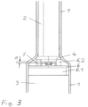
- FIG. 3 The part of an activated carbon filter unit is shown as an excerpt, which contains a heating device with a heating element 7 and a heat exchanger 6.
- the heating element 7 largely corresponds to that described above Figures 1 and 2 explained heating element.
- Fig. 3 shows a cylindrical absorption body 2, a so-called honeycomb, and the adjoining chamber 3 for an activated carbon bed, which has been omitted from the drawings for clarity.
- the heat exchanger 6 is at least partially embedded in activated carbon.
- the absorption body 2 is surrounded by an outer housing 1, preferably a plastic housing, which also forms the outer wall of the chamber 3 for the activated carbon bed.
- a transition area adapts the diameter of the larger chamber 3 with activated carbon fill approximately to the diameter of the cylindrical absorption body 2.
- the heating element 7 is arranged in this transition area. As can be seen from the drawing, the distance a between the end of the absorption body 2 and the heating element 7 is only a few mm, preferably between 2 mm and 10 mm. This allows the temperature of the activated carbon and the gas stream to be increased very effectively in this area.
- the heating element 7 is further connected in a heat-conducting manner to a heat exchanger 6, which in this exemplary embodiment has an outer cylindrical ring 6.1 which rests on the chamber wall or inside on the plastic housing 1.
- the heat exchanger 6 is thereby fixed in the chamber, and on the other hand, it is ensured that the entire gas stream flowing through the absorption body 2 also flows through the heat exchanger 6 and heats up in the process.
- the activated carbon bed is specifically heated in this area by the heat-conducting connection to the heat exchanger 6.
- the heat exchanger also has several webs 6.2 which project beyond the heating element 7 and fix the absorption body 2 in its position at this end. Furthermore, the webs 6.2 form a heat-conducting connection to the absorption body. As a result, the entire absorption body 2 also heats up, which significantly increases its effectiveness.
- a seal 4 is also fixed, which seals the absorption body 2 between its outside and the plastic housing 1.
- the heating element 7 has a two-part metal housing made of annular sheet metal parts 11 and 12, the lower housing part 11, which is U-shaped in section, forming the lower end face 11c and the two radially projecting side walls 11d, 11e.
- the upper part 12 is flat.
- the upper ends 11a, 11b of the side walls 11d, 11e are bent towards one another over the upper housing part 12, preferably rolled up. This results in a housing that is completely closed except for the area for leading out the electrical connections 14b, 15b.
- An annular PTC component 13 is arranged inside the two-part housing 11, 12. Its height h is less than its ring width b as the difference between the outer and inner radius. It is electrically contacted on its end faces by a contact element 14, 15.
- the upper contact element 14 is injected into a plastic frame 16.
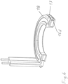
- Fig. 5 shown again in perspective, which shows the plastic frame 16 with the upper contact element 14.
- the lower contact element 15, which actually protrudes from the plastic frame 16 at point 16e, has been omitted for the sake of clarity.
- the plastic frame 16 is designed in such a way that an annular region 16a covers the top of the contact element 14a and two cylindrical side walls 16b and 16c extend from it, between which the annular PTC component 13 is inserted in contact with the section 14a of the contact element 14.
- the plastic frame 16 has an annular groove 16d on the outer circumference.
- a seal 17 is protrudingly inserted into this annular groove 16d.
- the seal 17 is designed as a two-lip shaped seal.
- a further seal 18 is arranged on the top of the annular area 16a. In the example shown, it is an annular shaped seal with edge areas thickened like a club. Both seals 17, 18 are elastically compression-formed between the plastic frame 16 and the two-part metal housing 11, 12 and thus reliably seal the PTC component 13 against external influences.
- Fig. 7 the two contact elements 14, 15 are shown separately again. They each consist of an annular region 14a and 15a, which is in electrical contact with one end face of the PTC component 13, and a strip-shaped region 14b, 15b for electrically contacting the heating element to the outside. Both strip-shaped areas 14b, 15b are tightly injected into the plastic frame 16, so that only the connection areas are exposed.
- the annular section 15a rests freely on the underside of the PTC component.
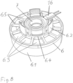
- Fig. 8 and 9 show the heating device consisting of heating element 7 and heat exchanger 6.
- the figures refer to a heating element 7, which is only connected to the heat exchanger 6 in a heat-conducting manner.
- heating element 7 and heat exchanger 6 can also be made in one piece.
- the heat exchanger 6 is also in Fig. 10 shown.
- the heat exchanger 6 has a connecting ring 6.6, which is connected flatly to the underside of the housing 11c of the heating element 7.
- the connecting ring 6.6 has approximately the same radial dimension as the underside of the housing 11c, so that a maximum heat transfer area is achieved without additional obstruction of the gas flow.
- an intermediate ring 6.4 is formed, which forms webs 6.2 in an axial extension in the direction of the absorption body 2, which fix the absorption body 2 and a seal 4 for the absorption body 2. Since only individual webs and no solid ring are formed, the gas stream flows in and out of the absorption body 2 is not hindered.
- the radial outside of the heat exchanger 6 is also formed by an outer ring 6.1, which in the exemplary embodiment Fig. 3 rests on the inside of the plastic housing 1.
- the openings 6.3 between the connecting webs 6.5 and the central opening 6.7 enable flow through the entire heat exchanger.
- the connecting webs 6.5 support an existing separating fleece (not shown).
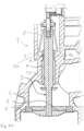
- Fig. 11 shows a section of a control valve 1 with a valve housing 2, the valve rod 3, the valve rod guide 4 connected in a heat-conducting manner to the valve housing 2, the valve plate 5 and the valve seat 6.
- the valve rod 3 is movably held in a guide channel 10, with between the guide channel 10 and the valve rod 3 has a small annular gap 9.
- a further exemplary embodiment of a heating element 7 is arranged, which essentially corresponds to the exemplary embodiments described above.
- the annular housing of the heating element 7 is pressed with its lower end face 7a against the bottom of the annular groove 2a by a spring element 8.
- the heat transfer from the heating element 7 to the valve housing 2 takes place predominantly via this lower end face 7a.
- the annular gap 9 and thus the frozen fluid or condensate located therein are heated via the valve rod guide 4, which is connected to the valve housing 2 in a heat-conducting manner and which at least partially forms the guide channel 10 and is itself also a good heat conductor.
- the valve housing 2 and the valve rod guide 4 can also be made in one piece.
- the heating element 7 can also be attached directly to the valve rod guide 4 in a heat-conducting manner.
Landscapes
- Engineering & Computer Science (AREA)
- General Engineering & Computer Science (AREA)
- Mechanical Engineering (AREA)
- Chemical & Material Sciences (AREA)
- Ceramic Engineering (AREA)
- Combustion & Propulsion (AREA)
- Resistance Heating (AREA)
Description
- Die Erfindung geht aus von einem ringförmigen Heizelement mit den im Oberbegriff des Anspruchs 1 angegebenen Merkmalen, wie es aus
US 4 390 000 bekannt ist. Ein ähnliches Heizelement ist ausUS 4 489 232 bekannt. - Ein ringförmiges Heizelement ist auch aus
DE 10 2014 109 273 A1 bekannt. Derartige Heizelemente werden beispielsweise zum Beheizen eines Regelventils, insbesondere eines Abgasrückführventils, einer Aktivkohlefiltereinheit, einer Düse, eines Injektors, eines Anschlussflansches einer Fluidleitung oder einer Kameralinse benötigt; kurz gesagt für Anwendungen, bei denen ein Objekt rundherum entlang einer Ringfläche beheizt werden soll. - Einzelheiten werden hierzu im Folgenden beispielhaft im Zusammenhang mit einem Regelventil erläutert. Regenventile bestehen im Wesentlichen aus einem Gehäuse mit einer Einlass- und Auslassöffnung. Dazwischen ist in einem Führungskanal eine beweglicher Ventilstange angeordnet, an deren einem Ende ein Ventilteller angebracht ist, der mit einem Ventilsitz zusammenwirkt, um den Durchgang zwischen Einlass- und Auslassöffnung freizugeben oder zu verschließen. Bei tiefen Temperaturen kann nun sowohl der Ventilteller am Ventilsitz, aber auch die Ventilstange im Bereich des Ringspaltes am Führungskanal durch Gefrieren des Förderfluids oder Kondensats festfrieren und das Ventil dadurch in seiner Funktion beeinträchtigen. Aus diesem Grunde sind sowohl Ventilsitzbeheizungen als auch Beheizungen, die den Ringspalt zwischen Ventilstange und Führungskanal beheizen, bekannt. So ist z.B. aus der
US6668854B2 eine Beheizung des Ringspaltes und des Ventiltellers bekannt, bei der die Beheizung in Form einer Heizpatrone erfolgt, die in einen Schacht des Gehäuses längsseits des Führungskanals eingebracht ist. Nachteilig dabei ist, dass der Führungskanal dabei nicht gleichmäßig von allen Seiten beheizt wird. Weiterhin nachteilig wird für den Schacht ein relativ dickes, massives Gehäuse benötigt, das den Schacht ausbilden kann. - Ähnliche Probleme stellen sich bei der Beheizung einer Aktivkohlefiltereinheit, wie sie beispielsweise zum Absorbieren von Kraftstoffgasen eingesetzt wird. Dabei kann durch die integrierte Heizung die Absorptions- und Abscheidungseffizienz durch die Erhöhung der Temperatur von Aktivkohle im Filter verbessert werden. Im Allgemeinen sammelt und speichert die Filtereinheit die Kraftstoffgase, insbesondere Kohlenwasserstoffe, die beim Stehen, Fahren und Betanken erzeugt werden und leitet sie mittels Spülluft, die durch den Motoransaugdruck erzeugt wird, an die Brennkammer weiter, wenn der Motor läuft. Damit benötigen schadstoffarme Fahrzeuge, vor allem auch Hybridfahrzeuge und Fahrzeuge mit einer Start-Stopp-Automatik sehr leistungsfähige Filter, da sie immer weniger Zeit zur Regeneration bei laufendem Motor haben.
- Eine Aktivkohlefiltereinheit weist in der Regel drei Fluidanschlüsse für Umgebungsluft, Kraftstofftank und Motoreinheit auf. Je nach Betriebszustand werden die Anschlüsse als Einlässe oder Auslässe betrieben. Zur Erhöhung der Leistungsfähigkeit und Regenerationsgeschwindigkeit ist es bekannt, PTC-Heizwiderstände in die Aktivkohlefiltereinheit zu integrieren. Dazu ist beispielweise in der
DE 10 2009 020 703 A1 ein Heizwiderstand vom luftseitigen Anschluss gesehen vor einem Absorptionskörper angeordnet, das im Regenerationsbetrieb die Temperatur der Ansaugluft durch den Absorptionskörper erhöht und dadurch der Absorptionskörper effektiver regeneriert werden kann. Ein weiterer Heizwiderstand ist zudem mitten in der Aktivkohleschüttung eingebettet, um auch bei dieser die Temperatur und dadurch die Regenerationgeschwindigkeit zu erhöhen. Bei den verwendeten Heizwiderständen handelt es sich um PTC-Heizwiderstände, die in Kanälen von Strangpressprofilen eingebracht sind. Die Außenwände der Kanäle und der damit verbundenen Wärmeabstrahlrippen stehen wiederum mit dem Aktivkohlegranulat bzw. mit einem Fluidstrom in wärmeleitender Verbindung, wobei die Strangpressrichtung in Strömungsrichtung orientiert ist, um eine möglichst effektive Wärmeübertragung zu gewährleisten. Nachteilig wird dafür ein erheblicher Bauraum und eine eigens dafür konstruierte Aktivkohlefiltereinheit benötigt. Außerdem sind die Kraftstoffgase sehr aggressiv. Die im Heizelement vorhandenen PTC-Steine sind in dieser Ausführung aber schwer gegen die Gase abzudichten, da ein Vergießen der Kanalöffnungen die PTC-Steine nicht zuverlässig gegen die aggressiven Gase abdichten kann. Im Absorptionsmodus kann diese Anordnung auch nicht ganz verhindern, dass kleinere Mengen der Gase ins Freie gelangen, was die strengen Abgasnormen z.B. in USA verbieten. - Vor diesem Hintergrund besteht die Aufgabe der Erfindung deshalb darin, ein Heizelement zu schaffen, das ein Objekt rundherum entlang einer Ringfläche beheizen kann und dabei gleichzeitig so kompakt ausgeführt ist, dass es relativ wenig Bauraum benötigt und einen einfachen Einbau ermöglicht. Zudem sollen die elektrischen Teile des Heizelements vor Umgebungseinflüssen geschützt werden können.
- Diese Aufgabe wird durch ein Heizelement mit den im Anspruch 1 angegebenen Merkmalen gelöst. Vorteilhafte Weiterbildungen der Erfindung sind Gegenstand von Unteransprüchen.
- Ein erfindungsgemäßes Heizelement hat ein Gehäuse, das ein ringförmiges Metallteil aufweist, das eine radial innere Wand, eine radial äußere Wand und eine erste stirnseitige Wand bildet. Sowohl an die radial innere Wand als auch an die radial äußere Wand grenzt jeweils ein Abschnitt an, der zumindest einen Teil einer zweiten stirnseitigen Wand, die der ersten stirnseitigen Wand gegenüberliegt, bildet. Das Metallteil ist bevorzugt aus Blech geformt, kann aber beispielsweise auch ein Druckguss- oder Fließpressteil sein. Bevorzugt ist das Blech gut wärmeleitend und daher aus Aluminium, Kupfer oder eine Legierung auf Basis dieser Metalle hergestellt.
- Ein solches Gehäuse kann mit vorteilhaft geringem Aufwand hergestellt werden, indem durch Tiefziehen, auch mehrstufig, aus einer Blechscheibe zunächst ein im Querschnitt U-förmiges Gehäuseteil hergestellt wird, das eine radial innere Wand, eine radial äußere Wand und eine erste stirnseitige Wand bildet.
- In das vorgeformte Gehäuseteil werden erfindungsgemäß dann Komponenten des Heizelements, insbesondere ein ringförmiger PTC-Heizwiderstand oder ringförmig angeordnete PTC-Widerstände sowie ein oder mehrere Kontaktelemente, beispielsweise zwei ringförmige Kontaktbleche, eingelegt. Danach wird erfindungsgemäß das Gehäuse geschlossen, indem obere Abschnitte von der radial inneren und der radial äußeren Seitenwand umgeklappt werden, so dass diese zumindest einen Teil der zweiten stirnseitigen Wand bilden, die der ersten stirnseitigen Wand gegenüber liegt. Ein solches Gehäuse hat zudem den Vorteil, dass es kompakt ist, eine gute Wärmeankopplung des PTC-Heizwiderstands ermöglicht und die darin angeordneten Komponenten des Heizelements vor Umgebungseinflüssen schützt. Ein weiterer Vorteil besteht darin, dass das Gehäuse mit geringem Aufwand abgedichtet werden kann.
- Die an die radial innere und die radial äußere Seitenwand anschließenden Abschnitte können auf der zweiten Stirnseite überlappen oder angrenzen und so die zweite Stirnseite vollständig ausbilden. Bevorzugt überlappen diese beiden Abschnitt jedoch nicht. Eine einfache Fertigung lässt sich realisieren, indem das Gehäuse ein zweites Gehäuseteil aufweist, das zusammen mit den beiden Abschnitten des ringförmigen Metallteils die zweite stirnseitige Wand bildet. Beispielsweise können der an die radial innere Seitenwand angrenzende Abschnitt und der an die radial äußere Seitenwand angrenzende Abschnitt jeweils einen Teil dieses zweiten Gehäuseteils bedecken und einen Bereich des zweiten Gehäuseteils zwischen dem an die radial innere Seitenwand und dem an die radial äußere Seitenwand angrenzenden Abschnitt unbedeckt lassen. Das zweite Gehäuseteil kann dabei vorteilhaft auch als Widerlager beim Umklappen der an die Seitenwände angrenzenden Abschnitte dienen und einen Druck in axialer Richtung auf die darunter angeordneten Komponenten des Heizelements weitergeben, so dass eine gute thermische Ankopplung des PTC-Heizwiderstands an das ringförmige Gehäuse erreicht wird.
- Das zweite Gehäuseteil ist bevorzugt aus Metall und kann beispielsweise eine Ringscheibe aus Blech sein, insbesondere aus Edelstahl. Möglich sind auch Kunststoff oder Keramik.
- Eine vorteilhafte Weiterbildung der Erfindung sieht vor, dass zur Abdichtung des Gehäuses unter der zweiten stirnseitigen Wand ein Dichtring angeordnet ist, beispielsweise ein elastomerer Dichtring. Auf diese Weise kann verhindert werden, dass Fluide durch einen Spalt zwischen den von den Seitenwänden ausgehenden Blechabschnitten elektrische Komponenten im Inneren des Gehäuses beinträchtigen. Dies ist beispielsweise bei Einsatz des Heizelements zur Beheizung eines Aktivkohlefilters ein wichtiger Vorteil, da auf diese Weise das Heizelement gegen die Kraftstoffgase ausreichend abgedichtet werden kann.
- In einem erfindungsgemäßen Heizelement kann der PTC-Heizwiderstand auf einer Seite von einem oder mehreren Kontaktelementen und auf der gegenüberliegenden Seite von dem Gehäuse kontaktiert werden. Bevorzugt ist aber, dass der PTC-Heizwiderstand auf gegenüberliegenden Seiten jeweils von einem Kontaktelement elektrisch kontaktiert wird.
- Eine weitere vorteilhafte Weiterbildung der Erfindung sieht vor, dass von einem bevorzugt ringförmigen Kontaktelement oder von den Kontaktelementen jeweils ein streifenförmiger Anschlussabschnitt ausgeht. Dieser Anschlussabschnitt kann beispielsweise in einem Kontaktstift eines Steckverbinders enden oder an einen Kontaktstift eines Steckverbinders angeschlossen sein. Der Anschlussabschnitt oder die Anschlussabschnitte sind bevorzugt aus der radial äußeren Seitenwand herausgeführt; eine Aussparung dafür kann aber beispielsweise auch in einer der Stirnseiten vorgesehen sein. Um eine Aussparung in der radial äußeren Seitenwand abzudichten, kann zwischen der radial äußeren Seitenwand und dem bzw. den Anschlussabschnitten ein Dichtring, insbesondere ein Dichtring aus einem elastomeren Material angeordnet sein.
- Der Anschlussabschnitt oder die Anschlussabschnitte können mit Kunststoff umspritzt sein. Diese Kunststoffumspritzung kann ein Steckergehäuse und/oder einen Rahmen bilden, der den PTC-Heizwiderstand sowie das Kontaktelement oder die Kontaktelemente hält.
- In einer vorteilhaften Weiterbildung der Erfindung ist mindestens ein Kontaktelement in einen Kunststoffrahmen eingespritzt. Dabei ist der Kunststoffrahmen bevorzugt so ausgeführt, dass er im ringförmigen Abschnitt des Kontaktelementes eine Oberseite des Kontaktelementes bedeckt und davon ausgehend zwei zylindrische Seitenwände aufweist, zwischen denen der ringförmige PTC-Heizwiderstand in Kontakt mit der Unterseite des Kontaktelementes eingelegt ist. Der streifenförmige Abschnitt ist bis auf den Anschlussbereich vollständig vom Kunststoffrahmen umspritzt.
- In einer äußerst bevorzugten Ausgestaltung ist der streifenförmige Abschnitt eines zweiten Kontaktelementes ebenfalls in den Kunststoffrahmen eingespritzt. Der ringförmige Abschnitt dagegen liegt frei an der Unterseite des PTC-Heizwiderstands an.
- Der PTC-Heizwiderstand ist bevorzugt aus einem keramischen Material, insbesondere auf Basis von Bariumtitanat, hergestellt. Vorzugsweise ist der PTC-Heizwiderstand ringförmig oder setzt sich aus mehreren ringförmig angeordneten Einzelkomponenten zusammen. Weiterhin bevorzugt ist dieser von dem PTC-Heizwiderstand gebildete Ring ein Kreisring, der so dimensioniert ist, dass die Höhe h des Rings geringer ist als seine Ringbreite b als Differenz zwischen äußerem und innerem Radius. Dies ermöglicht eine platzsparende Ausführung des gesamten Heizelements.
- Ein erfindungsgemäßes Heizelement kann, beispielsweise zum Beheizen eines Aktivkohlefilters, mit einem Wärmeübertrager versehen werden, beispielsweise in Form von Ringen, Rippen, Lamellen, Stegen oder Kombinationen davon, die an dem Gehäuse angebracht sind oder von ihm ausgehen. Insbesondere kann auch das Gehäuse selbst als Wärmeübertrager dienen. Ein erfindungsgemäßes Heizelement zusammen mit einem Wärmeübertrager wird im Folgenden als Heizeinrichtung bezeichnet. Sie kann beispielsweise Teil einer Aktivkohlefiltereinheit sein, die einen Absorptionskörper und eine räumlich daran anschließende Kammer mit einer Kammerwand für eine Aktivkohleschüttung aufweist.
- Durch eine Heizeinrichtung in einer Aktivkohlefiltereinheit soll in der Regel die Abgasmenge, die im Absorptionsbetrieb ins Freie gelangt, weiter reduziert werden. Zudem soll die Leistungsfähigkeit und Regenerationsgeschwindigkeit der Aktivkohlefiltereinheit durch die Heizeinrichtung erhöht werden und für diese möglichst wenig eigener Bauraum benötigt werden.
- Mit der Anordnung einer erfindungsgemäßen Heizeinrichtung im vom luftseitigen Anschluss gesehenen Übergangsbereich vom Absorptionskörper zur Aktivkohleschüttung hin lässt sich die Temperatur der Aktivkohle in diesem Bereich gezielt lokal erhöhen, um in den kurzen Regenerationsphasen komplett entladen zu werden und dann in der Absorptionsphase wieder maximal aufnahmefähig zu sein. Durch die gezielte Beheizung an dieser Stelle kann daher ein Gasaustritt in die Umwelt (sogenannter Schlupf) sicher verhindert werden. Vorteilhaft kann dies mit der erfindungsgemäßen Heizeinrichtung und Aktivkohlefiltereinheit erreicht werden, ohne dass Veränderungen der äußeren Abmessungen des Filtersystems und insbesondere der Gestaltung des Kraftstoffbehälters erforderlich sind. Aber selbst der innere Aufbau der Filtereinheit muss durch die Integration einer erfindungsgemäßen Heizung kaum verändert werden.
- Bevorzugt weist dabei das Heizelement ein dichtes Gehäuse wie oben beschrieben auf, das einen PTC-Heizwiderstand, beispielsweise einen Ring-PTC oder mehrere zu einem Ring angeordnete PTC-Elemente, im Inneren gegen die aggressiven Kraftstoffgase ausreichend abdichtet. Äußerst bevorzugt ist das Gehäuse ein bis auf den Bereich zum Herausführen der elektrischen Anschlüsse geschlossenes mehrteiliges, bevorzugt zweiteiliges, Gehäuse, insbesondere ein gut wärmeleitendes Metallgehäuse. Durch dieses Gehäuse ist das Heizelement vorteilhaft als vorgefertigte, kompakte Einheit handhabbar.
- In einer vorteilhaften Weiterbildung sind die Gehäuseteile unter Druckbeaufschlagung in Richtung der Stirnseiten des PTC-Heizwiderstands zusammengefügt. Durch die Druckbeaufschlagung ist ein guter Wärmeübergang zwischen dem PTC-Heizwiderstand und dem Gehäuse gewährleistet. Äußerst bevorzugt ist dabei das Gehäuse zweiteilig mit einem im Schnitt U-förmigen Gehäuseunterteil und einem flachen Gehäusedeckel, der auch als zweites Gehäuseteil bezeichnet wird, ausgeführt, wobei die beiden Gehäuseteile durch Umbiegen, insbesondere Einrollen, der oberen Enden des Gehäuseunterteiles über dem Gehäusedeckel verbunden sind.
- Wie bereits erwähnt, wird der PTC-Heizwiderstand durch mindestens ein Kontaktelement, das bevorzugt mit einem ringförmigen und einem streifenförmigen Abschnitt versehen ist, der vorstehend als Anschlussstreifen bezeichnet wird, an einer Stirnseite elektrisch kontaktiert. Äußerst bevorzugt weisen beide Stirnseiten ein Kontaktelement mit einem ringförmigen und einem streifenförmigen Abschnitt auf.
- In einer bevorzugten Weiterbildung ist der PTC-Heizwiderstand durch jeweils ein Dichtelement, beispielsweise einen elastomeren Dichtring, umlaufend am Außenumfang und auf der Oberseite des Kunststoffrahmens im Gehäuse nach außen abgedichtet angeordnet. Dadurch ist es ermöglicht, dass der PTC-Heizwiderstand gegen aggressive Einflüsse geschützt ist, was wesentlich zur Verlängerung der Lebensdauer und zur Verhinderung von vorzeitigen Ausfällen beiträgt.
- Bei einem erfindungsgemäßen Heizelement kann der Heizwiderstand wärmeleitend mit einem Wärmeübertrager verbunden sein. Bevorzugt ist dabei das Gehäuse des Heizelements stoffschlüssig mit dem Wärmeübertrager verbunden, insbesondere sind Gehäuse und Wärmeübertrager einstückig ausgeführt.
- Bei Verwendung in einer Aktivkohlefiltereinheit lässt sich durch die damit erreichte vergrößerte Wärmeübertragungsfläche die Temperatur der Aktivkohle in der Regenerationsphase wirksam erhöhen und damit die Effizienz der Aktivkohlefiltereinheit verbessern.
- Bei einer bevorzugten Ausgestaltung weist der Wärmeübertrager eine radial größere Ausdehnung auf als das Heizelement. Der Wärmeübertrager kann im Wesentlichen gitterartig ausgeführt und dabei mit Durchbrüchen versehen sein, die ein Durchströmen in axialer Richtung erlauben. Äußerst bevorzugt weist der Wärmeübertrager sowohl im radial kleineren Bereich als auch im radial größeren Bereich des Heizelements Durchbrüche auf. Dadurch ist es einem Fluidstrom ermöglicht, sowohl innen als auch außen am Gehäuse in radialer Richtung vorbei zu strömen und sich dabei zu erwärmen.
- In einer erfindungsgemäßen Weiterbildung weist der Wärmeübertrager zumindest einen äußeren und einen inneren Ring mit Verbindungsstegen dazwischen auf, wobei der innere Ring wärmeleitend, insbesondere stoffschlüssig mit dem Gehäuse verbunden ist.
- In einer vorteilhaften Ausbildung weist der Wärmeübertrager weiterhin einzelne axial ausgerichtete Stifte oder Klemmen auf, mit deren Hilfe das Gehäuse am Wärmeübertrager befestigt wird. Die Befestigung erfolgt dabei bevorzugt formschlüssig, beispielsweise durch Verstemmen oder Klemmen.
- Aktivkohlefiltereinheiten sind meist mehrstufig ausgebildet, wobei ein monolithischer, zum Durchströmen bestimmter zylindrischer Absorptionskörper einer Kammer mit einer Aktivkohleschüttung strömungsmäßig je nach Betriebszustand vor- oder nachgeschaltet ist. Ein Übergangsbereich passt den Durchmesser der größeren Kammer mit Aktivkohleschüttung dem Durchmesser des zylindrischen Absorptionskörpers an.
- Bei einer Aktivkohlefiltereinheit mit einer erfindungsgemäßen Heizeinrichtung ist das Heizelement bevorzugt in diesem Übergangsbereich angeordnet. Äußerst bevorzugt ist das Heizelement dabei in geringem Abstand vom Lufteinlass entfernten Ende des Absorptionskörpers angeordnet, insbesondere ist das Heizelement im Abstand von 1mm-5mm angeordnet. Vorteilhaft können dabei der zylindrische Absorptionskörper und der Ring, der durch den ringförmigen PTC-Heizwiderstand oder die ringförmig angeordneten PTC-Heizwiderstände definiert ist, die gleiche Mittelachse haben. Bevorzugt haben der zylindrische Absorptionskörper und das ringförmige Gehäuse die gleiche Mittelachse.
- Durch diese Anordnung ist bewirkt, dass der gesamte Gasstrom, der im Regenerationsbetrieb aus dem Absorptionskörper ausströmt, nahe an dem Heizelement und am Wärmeübertrager vorbeiströmen muss und dabei erwärmt wird. Weiterhin ist bevorzugt der Wärmeübertrager auch wärmeleitend mit dem Absorptionskörper direkt oder über ein Verbindungselement wie eine Dichtung wärmeleitend mit dem Absorptionskörper verbunden. Somit wird auch dieser von der Heizeinrichtung erwärmt. Besonders vorteilhaft ist jedoch bei sehr kurzen Regenerationszeiten, dass zumindest die Aktivkohleschüttung im unmittelbaren Bereich des vom luftseitigen Anschluss gesehenen Übergangsbereich vom Absorptionskörper zur Aktivkohleschüttung hin gezielt sowohl durch den erwärmten Luftstrom als auch durch die direkte wärmeleitende Verbindung zum Wärmeübertrager lokal schnell erwärmt wird, wodurch die Bindungsenergie beschleunigt überwunden wird und zumindest in diesem Bereich die Aktivkohle in kürzester Zeit vollständig regeneriert werden kann. Im Absorptionsbetrieb ist dann gerade im Bereich des luftseitigen Anschlusses zum Absorptionskörper hin eine große Aufnahmefähigkeit vorhanden, die jeglichen Schlupf verhindert.
- Die Ausgestaltung der Heizeinrichtung mit einem ringförmigen Heizelement und einem Wärmeübertrager, der das radiale Vorbeiströmen eines Gasstromes sowohl innen als auch außen am Heizelement ermöglicht, ist gerade bei Anordnung in der Nähe des zylindrischen Absorptionskörpers äußerst vorteilhaft, da so der gesamte Gasstrom nahe am Heizelement vorbeiströmt, ohne dass der Gasstrom beim Ein- oder Ausströmen in den Absorptionskörper wesentlich behindert wird. Bei Ausbildung einer wärmeleitenden Verbindung zum Absorptionskörper erwärmt sich zusätzlich der gesamte Absorptionskörper, was seine Effektivität wesentlich erhöht.
- Eine vorteilhafte Weiterbildung sieht vor, dass der Wärmeübertrager sich über den gesamten Querschnitt der Kammer oder des Übergangbereiches erstreckt. Dadurch durchströmt der gesamte Gasstrom durch den Absorptionskörper auch den Wärmeübertrager und wird dabei relativ homogen aufgeheizt.
- Auf der dem Heizelement abgewandten Seite des Wärmeübertragers ist ein Trennvlies angeordnet, das die in die Kammer eingeschüttete Aktivkohle in der Kammer zurückhält und ein Eindringen der Aktivkohleschüttung in den Absorptionskörper verhindert. Die Gitterstruktur des Wärmeübertragers dient dabei gleichzeitig zum Abstützen des Trennvlieses und übernimmt so die Funktion eines ansonsten hierfür extra benötigten Bauteils.
- Bevorzugt weist der Wärmeübertrager einen äußeren Ring auf, der an der Kammerwand anliegt. Dieser äußere Ring weist äußerst bevorzugt eine erhebliche axiale Länge auf. Vernachlässigt man die Vliesdicke, steht der Wärmeübertrager auf dieser gesamten Länge direkt mit der Aktivkohle in Verbindung und kann so Wärme auf sie übertragen. Besonders vorteilhaft wird dadurch die Aktivkohle lokal im Bereich des Wärmetauschers auch bei kurzen Regenerationszeiten so stark aufgeheizt, dass sie vollständig regeneriert und im Absorptionsbetrieb die Kraftstoffgase vor Austritt durch den Luftauslass vollständig aufnimmt, sodass sie nicht in die Umwelt gelangen.
- Vorteilhaft übernimmt der Wärmeübertrager auch noch weitere Aufgaben, wie z.B. das Fixieren des Absorptionskörpers und oder einer Dichtung, und ersetzt dadurch andere Bauteile, sodass kein zusätzlicher Bauraum für den Wärmeübertrager benötigt wird.
- Wenn ein erfindungsgemäßes Heizelement beispielsweise zum Beheizen eines Regelventils eingesetzt wird, kann der PTC-Heizwiderstand bzw. das ihn umgebende ringförmige Gehäuse einen Ringspalt zwischen Führungskanal und Ventilstange umschließen.
- Damit das Heizelement beim Beheizen eines Regelventiles seine Wärme gut auf das Ventilgehäuse im Bereich des Ringspaltes zwischen Führungskanal und Ventilstange übertragen kann, ist das Gehäuse des Heizelements in gut wärmeleitendem Kontakt zumindest einer Stirnseite des Heizelements zum Ventilgehäuse, bevorzugt in einer ringförmige Nut oder einem ringförmigen Absatz des Ventilgehäuses, angeordnet. Die Befestigung kann beispielsweise durch Federdruck oder durch Verkleben erfolgen.
- Das Heizelement gibt dabei überwiegend über zumindest eine Stirnseite seine Wärme an das Ventilgehäuse ab. Ein radialer Wärmefluss von dem Heizelement in Richtung Ringspalt findet dabei kaum statt. Überraschend hat sich aber gezeigt, dass durch die kompakte, wenig Bauraum beanspruchende Ausführung des erfindungsgemäßen Heizelements trotzdem ein schnelleres Freischmelzen des Ringspaltes ermöglicht wird als bei Ausführungen mit einem direkten, radialen Wärmefluss.
- Weitere Einzelheiten und Vorteile der Erfindung werden an Ausführungsbeispielen unter Bezugnahme auf die Beigefügten Zeichnungen erläutert. Gleiche und einander entsprechende Komponenten sind darin mit übereinstimmenden Bezugszeichen bezeichnet. Es zeigen:
- Fig. 1
- ein Ausführungsbeispiel eines erfindungsgemäßen Heizelements;
- Fig. 2
- eine Schnittansicht zu
Fig. 1 ; - Fig. 3
- die Anordnung eines weiteren Ausführungsbeispiels eines erfindungsgemäßen Heizelements in einem Auszug eines Aktivkohlefiltersystems, der einen Absorptionskörper und eine Kammer für eine Aktivkohleschüttung darstellt;
- Fig. 4
- einen Schnitt durch das Heizelement von
Fig. 3 ; - Fig. 5
- den Kunststoffrahmen des Heizelements von
Fig. 3 mit dem oberen Kontaktelement; - Fig. 6
- einen Schnitt durch das Heizelement von
Fig. 3 ohne Gehäuse; - Fig. 7
- die beiden Kontaktelemente des PTC-Heizwiderstands des Heizelements von
Fig. 3 ; - Fig. 8
- das Heizelement von
Fig. 3 mit Wärmeübertrager in perspektivischer Ansicht; - Fig. 9
- eine Schnittansicht zu
Fig. 8 ; - Fig. 10
- den Wärmeübertrager von
Fig. 8 in perspektivischer Ansicht; und - Fig. 11
- einen Ausschnitt eines Regelventiles mit einem weiteren Ausführungsbeispiel eines Heizelements.
- In den
Figuren 1 und 2 ist ein Heizelement 7 dargestellt, das einen PTC-Heizwiderstand 13 in einem ringförmigen Gehäuse aufweist. Der PTC-Heizwiderstand kann beispielsweise ein ringförmiges Element aus einer PTC-Keramik sein oder aus mehreren ringförmig angeordneten Teilen bestehen. Das Gehäuse ist ein mehrteiliges Gehäuse aus Metall. Bei dem gezeigten Ausführungsbeispiel ist das Gehäuse aus zwei ringförmigen Metallteilen 11, 12 beispielsweise Blechteilen, gebildet. Ein erstes ringförmiges Blechteil 11 bildet eine radial innere Wand 11d, eine radial äußere Wand 11e und eine erste stirnseitige Wand 11c. Die zweite stirnseitige Wand wird von dem ersten ringförmigen Blechteil 11 und dem zweiten ringförmigen Blechteil 12 gebildet, indem ein Blechabschnitt 11a des ersten Blechteils 11, der an die radial innere Wand 11d angrenzt, und ein Blechabschnitt 11b des ersten Blechteils 11, der an die radial äußere Wand 11e angrenzt, auf dem zweiten ringförmigen Blechteil 12 liegen. Das erste Blechteil 11 kann beispielsweise aus Aluminium und das zweite Blechteil 12 aus Edelstahl sein. - Bei der Herstellung werden die Blechabschnitte 11a und 11b erst umgebogen, nachdem der PTC-Heizwiderstand 13 und weitere Komponenten des Heizelements einschließlich des Blechteils 12 in eine von dem Blechteil 11 gebildete Nut eingelegt wurden. Die Blechabschnitte 11a, 11b werden dann unter Druckbeaufschlagung umgeklappt, so dass sie gegen das Blechteil 12 drücken und so eine gute Wärmeankopplung des PTC-Heizwiderstands 13 an das Gehäuse bewirken.
- Der PTC-Heizwiderstand 13 wird in dem Gehäuse von Kontaktelementen 14, 15, beispielsweise aus Blech, elektrisch kontaktiert. Die Kontaktelemente 14, 15 sind bevorzugt ringförmig und haben jeweils einen streifenförmigen Anschlussabschnitt, der aus dem Metallgehäuse herausgeführt ist und beispielsweise einen Kontaktstift eines Steckverbinders bilden kann. Die Anschlussabschnitte der Kontaktelemente 14, 15 sind mit Kunststoff 16 umspritzt, der ein Steckergehäuse bildet. Der Kunststoff 16 kann dabei zusätzlich auch einen Kunststoffrahmen bilden, der die Kontaktelemente 14, 15 und den PTC-Heizwiderstand 13 hält. Die mit Kunststoff 16 umspritzten Kontaktelemente 14, 15 und der PTC-Heizwiderstand 13 können so vormontiert werden und dann als Einheit in das Blechteil 11 des Gehäuses eingelegt werden.
- Um die elektrischen Komponenten des Heizelements vor Umgebungseinflüssen zu schützen, können in dem Metallgehäuse Dichtelemente 17, 18 angeordnet sein. Bei dem gezeigten Ausführungsbeispiel drückt das Blechteil 12 gegen einen darunter liegenden Dichtring 18. Zudem ist zwischen der radial äußeren Wand 11e und dem die Anschlussabschnitte der Kontaktelemente 14, 15 umgebenden Kunststoff 16 bzw. dem daraus gebildeten Kunststoffrahmen ein Dichtring 17 angeordnet. Die Dichtringe 17, 18 können beispielsweise aus elastomerem Kunststoff sein.
- Die Dichtungen 17, 18 sowie der Kunststoff bewirken eine gewisse thermische Isolation, so dass der PTC-Heizwiderstand 13 überwiegend über eine Strinseite Wärme an sein Gehäuse abgibt.
- In
Fig. 3 ist als Auszug der Teil einer Aktivkohlefiltereinheit dargestellt, der eine Heizeinrichtung mit einem Heizelement 7 und einem Wärmeübertrager 6 beinhaltet. Das Heizelement 7 entspricht weitgehend dem vorstehend anhand derFiguren 1 und 2 erläuterten Heizelement.Fig. 3 zeigt einen zylindrischen Absoptionskörper 2, eine sogenannte Honeycomb, und die daran anschließende Kammer 3 für eine Aktivkohleschüttung, die in den Zeichnungen wegen der Übersichtlichkeit weggelassen wurde. Tatsächlich aber ist der Wärmeübertrager 6 zumindest zum Teil in Aktivkohle eingebettet. Der Absorptionskörper 2 ist von einem äußeren Gehäuse 1, bevorzugt ein Kunststoffgehäuse, umgeben, das auch die äußere Wand der Kammer 3 für die Aktivkohleschüttung bildet. Ein Übergangsbereich passt dabei den Durchmesser der größeren Kammer 3 mit Aktivkohleschüttung in etwa dem Durchmesser des zylindrischen Absorptionskörpers 2 an. Das Heizelement 7 ist dabei in diesem Übergangsbereich angeordnet. Wie man der Zeichnung entnehmen kann, beträgt der Abstand a zwischen dem Ende des Absorptionskörpers 2 und dem Heizelement 7 nur wenige mm, bevorzugt zwischen 2 mm und 10 mm. Dadurch kann die Temperatur der Aktivkohle und des Gasstromes in diesem Bereich sehr wirksam erhöht werden. Das Heizelement 7 ist weiterhin wärmeleitend mit einem Wärmeübertrager 6 verbunden, der in dieser beispielhaften Ausgestaltung einen äußeren zylindrischen Ring 6.1 aufweist, der an der Kammerwand bzw. innen am Kunststoffgehäuse 1 anliegt. Zum einen ist der Wärmeübertrager 6 dadurch in der Kammer fixiert, zum anderen ist gewährleistet, dass dadurch der gesamte den Absorptionskörper 2 durchströmende Gasstrom auch den Wärmeübertrager 6 durchströmt und sich dabei erwärmt. Zusätzlich wird die Aktivkohleschüttung gezielt in diesem Bereich durch die wärmeleitende Verbindung zum Wärmeübertrager 6 erwärmt. - Der Wärmeübertrager weist weiterhin mehrere Stege 6.2 auf, die das Heizelement 7 überragen und den Absorptionskörper 2 an diesem Ende in seiner Lage fixieren. Weiterhin bilden die Stege 6.2 eine wärmeleitende Verbindung zum Absorptionskörper. Dadurch erwärmt sich zusätzlich der gesamte Absorptionskörper 2, was seine Effektivität wesentlich erhöht. In dieser Ausgestaltung erfolgt zusätzlich noch die Fixierung einer Dichtung 4, die den Absorptionskörper 2 zwischen seiner Außenseite und dem Kunststoffgehäuse 1 abdichtet. Dadurch werden andere Bauteile, die diese Funktionen gewährleisten sollen, eingespart beziehungsweise ersetzt, wodurch die Heizeinrichtung keinen zusätzlichen Bauraum benötigt und die Anzahl der Einzelteile nicht erhöht werden muss.
- In
Fig. 4 ist das Heizelement 7 im Schnitt gezeigt. Aus Übersichtsgründen sind hierbei die beiden eigentlich vorhandenen umlaufenden Dichtungen 16, 17 weggelassen. Das Heizelement 7 weist ein zweiteiliges Metallgehäuse aus ringförmigen Blechteilen 11 und 12 auf, wobei der im Schnitt U-förmige untere Gehäuseteil 11 die untere Stirnseite 11c und die beiden radial aufstehenden Seitenwände 11d, 11e bildet. Der obere Teil 12 ist flach ausgeführt. Die oberen Enden 11a, 11b der Seitenwände 11d, 11e sind über dem oberen Gehäuseteil 12 aufeinander zu umgebogen, bevorzugt eingerollt. Dadurch ist ein, bis auf den Bereich zum Herausführen der elektrischen Anschlüsse 14b, 15b, rundum geschlossenes Gehäuse gegeben. Im Inneren des zweiteiligen Gehäuses 11, 12 ist ein ringförmiger PTC-Baustein 13 angeordnet. Seine Höhe h ist geringer als seine Ringbreite b als Differenz zwischen äußerem und innerem Radius. An seinen Stirnseiten ist er jeweils von einem Kontaktelement 14, 15 elektrisch kontaktiert. - Das obere Kontaktelement 14 ist in einen Kunststoffrahmen 16 eingespritzt. Dies ist in
Fig. 5 nochmals perspektivisch dargestellt, die Kunststoffrahmen 16 mit dem oberen Kontaktelement 14 zeigt. Das untere Kontaktelement 15, das eigentlich an der Stelle 16e aus dem Kunststoffrahmen 16 herausragt, ist der Übersicht wegen weggelassen. Der Kunststoffrahmen 16 ist so ausgeführt, dass ein ringförmiger Bereich 16a die Oberseite des Kontaktelementes 14a bedeckt und sich davon ausgehend zwei zylindrische Seitenwände 16b und 16c erstrecken, zwischen denen der ringförmige PTC-Baustein 13 in Kontakt mit dem Abschnitt 14a des Kontaktelementes 14 eingelegt ist. - Dies ist besonders in
Fig. 6 zu erkennen, wobeiFig. 6 das Heizelement 7 nun ohne Metallgehäuse darstellt. Der Kunststoffrahmen16 weist am Außenumfang eine Ringnut 16d auf. In diese Ringnut 16d ist eine Dichtung 17 überstehend eingebracht. Im vorliegenden Beispiel ist die Dichtung 17 als zweilippige Formdichtung ausgeführt. Auf der Oberseite des ringförmigen Bereiches 16a ist eine weitere Dichtung 18 angeordnet. Im ausgeführten Beispiel ist es eine ringförmige Formdichtung mit keulenartig verdickten Randbereichen. Beide Dichtungen 17, 18 sind elastisch zwischen dem Kunststoffrahmen 16 und dem zweiteiligen Metallgehäuse 11, 12 druckverformt und dichten somit den PTC-Baustein 13 gegen Einflüsse von außen zuverlässig ab. - In
Fig. 7 sind die beiden Kontaktelemente 14, 15 nochmals separat dargestellt. Sie bestehen jeweils aus einem ringförmigen Bereich 14a und 15a, der in elektrischem Kontakt mit jeweils einer Stirnseite des PTC-Bausteines 13 steht, und aus einem streifenförmigen Bereich 14b, 15b zur elektrischen Kontaktierung des Heizelementes nach außen. Beide streifenförmigen Bereiche 14b, 15b sind in den Kunststoffrahmen 16 dicht eingespritzt, sodass nur die Anschlussbereiche frei liegen. Der ringförmige Abschnitt 15a dagegen liegt frei an der Unterseite des PTC-Bausteines an. -
Fig. 8 und9 zeigen die Heizeinrichtung aus Heizelement 7 und Wärmeübertrager 6. Die Figuren beziehen sich dabei auf ein Heizelement 7, das lediglich wärmeleitend mit dem Wärmeübertrager 6 verbunden ist. In einer anderen Ausgestaltungsvariante können Heizelement 7 und Wärmeübertrager 6 jedoch auch einstückig ausgeführt sein. - Der Wärmeübertrager 6 ist zudem in
Fig. 10 dargestellt. Für eine wärmeleitenden Verbindung gemäß denFig. 8 und9 weist der Wärmeübertrager 6 einen Verbindungsring 6.6 auf, der flächig mit der Gehäuseunterseite 11c des Heizelementes 7 verbunden ist. Im Ausführungsbeispiel hat dabei der Verbindungsring 6.6 in etwa die gleiche radiale Dimension wie die Gehäuseunterseite 11c, sodass eine maximale Wärmeübertragungsfläche ohne zusätzliche Behinderung des Gasstromes erreicht ist. - Weiterhin ist ein Zwischenring 6.4 ausgebildet, der in axialer Verlängerung in Richtung Absorptionskörper 2 Stege 6.2 ausbildet, die den Absorptionskörper 2 und eine Dichtung 4 für den Absorptionskörper 2 fixieren. Da nur einzelne Stege und kein massiver Ring ausgebildet ist, ist ein Ein- und Ausströmen des Gasstromes in den Absorptionskörper 2 nicht behindert.
- Die radiale Außenseite des Wärmeübertragers 6 ist ebenfalls von einem äußeren Ring 6.1 gebildet, der in der beispielhaften Ausgestaltung nach
Fig. 3 an der Innenseite des Kunststoffgehäuses 1 anliegt. Zwischen den einzelnen Ringen 6.6, 6.4, 6.1 sind Verbindungsstege 6.5 vorhanden. Die Durchbrüche 6.3 zwischen den Verbindungsstegen 6.5 und der zentrale Durchbruch 6.7 ermöglichen ein Durchströmen des gesamten Wärmeübertragers. Gleichzeitig stützen die Verbindungsstege 6.5 ein vorhandenes Trennvlies (nicht gezeigt) ab. -
Fig. 11 zeigt einen Ausschnitt eines Regelventils 1 mit einem Ventilgehäuse 2, der Ventilstange 3, der wärmeleitend mit dem Ventilgehäuse 2 verbundenen Ventilstangenführung 4, dem Ventilteller 5 und dem Ventilsitz 6. Die Ventilstange 3 ist dabei beweglich in einem Führungskanal 10 gehalten, wobei zwischen dem Führungskanal 10 und der Ventilstange 3 ein kleiner Ringspalt 9 gegeben ist. In einer Ringnut 2a des Ventilgehäuses 2, die rings um die Ventilstange 3 gelagert ist, ist ein weiteres Ausführungsbeispiel eines Heizelements 7 angeordnet, die im Wesentlichen mit den vorstehend beschriebenen Ausführungsbeispielen übereinstimmt. - Das ringförmige Gehäuse des Heizelements 7 wird mit seiner unteren Stirnseite 7a durch ein Federelement 8 gegen den Boden der Ringnut 2a gedrückt. Dabei erfolgt die Wärmeübertragung vom Heizelement 7 auf das Ventilgehäuse 2 überwiegend über diese untere Stirnseite 7a. Die Beheizung des Ringspaltes 9 und damit des darin befindlichen eingefrorenen Fluides oder Kondensates erfolgt über die wärmeleitend mit dem Ventilgehäuse 2 verbundene Ventilstangenführung 4, die wenigstens teilweise den Führungskanal 10 ausbildet und selbst auch gut wärmeleitend ist. In einer alternativen Ausbildung können das Ventilgehäuse 2 und die Ventilstangenführung 4 auch einstückig ausgeführt sein. Ebenso kann das Heizelement 7 auch direkt an der Ventilstangenführung 4 wärmeleitend angebracht sein.
Claims (15)
- Heizelement miteinem ringförmigen Gehäuse, in dem ein PTC-Heizwiderstand (13) und ein Kontaktelement (14, 15), das den PTC-Heizwiderstand (13) kontaktiert, angeordnet sind,wobei das Gehäuse ein ringförmiges Metallteil (11) aufweist, das eine radial innere Wand (11d), eine radial äußere Wand (11e) und eine erste stirnseitige Wand (11c) bildet, dadurch gekennzeichnet, dasssowohl an die radial innere Wand (11d) als auch an die radial äußere Wand (11e) jeweils ein Abschnitt (11a, 11b) angrenzt, der zumindest einen Teil einer zweiten stirnseitigen Wand des Gehäuses, die der ersten stirnseitigen Wand (11c) gegenüberliegt, bildet und nach dem Einlegen des PTC-Heizwiderstands (13) und des Kontaktelements (14, 15) umgeklappt wurde.
- Heizelement nach Anspruch 1 dadurch gekennzeichnet, dass das Gehäuse ein zweites Gehäuseteil (12) aufweist, das zusammen mit den beiden Abschnitten (11a, 11b) des ringförmigen Metallteils (11) die zweite stirnseitige Wand bildet.
- Heizelement nach Anspruch 2, dadurch gekennzeichnet, dass der an die radial innere Seitenwand (11d) angrenzende Abschnitt (11a) und der an die radial äußere Seitenwand (11e) angrenzenden Abschnitt (11e) jeweils einen Teil des zweiten Gehäuseteils (12) bedecken und ein Bereich des zweiten Gehäuseteils (12) zwischen dem an die radial innere Seitenwand (11d) und dem an die radial äußere Seitenwand (11e) angrenzenden Abschnitt (11a, 11b) von diesen beiden Abschnitten (11, 11b) unbedeckt ist.
- Heizelement nach einem der vorstehenden Ansprüche, dadurch gekennzeichnet, dass zur Abdichtung des Gehäuses unter der zweiten stirnseitigen Wand ein Dichtring (18) angeordnet ist.
- Heizelement nach einem der vorstehenden Ansprüche, dadurch gekennzeichnet, dass das PTC-Heizelement (13) und das Kontaktelement (14, 15) von einem Kunststoffrahmen in dem Gehäuse gehalten werden.
- Heizelement nach einem der vorstehenden Ansprüche, dadurch gekennzeichnet, dass von dem Kontaktelement (14, 15) ein Anschlussstreifen ausgeht, der durch eine Aussparung des ringförmigen Blechteils (11) hindurch ragt.
- Heizelement nach Anspruch 6, dadurch gekennzeichnet, dass der Anschlussstreifen mit Kunststoff (16) umspritzt ist.
- Heizelement nach Anspruch 5 und 7, dadurch gekennzeichnet, dass die Umspritzung des Anschlussstreifens den Kunststoffrahmen und ein Steckergehäuse bildet.
- Heizelement nach Anspruch 8, dadurch gekennzeichnet, dass das
Kontaktelement (14) in den Kunststoffrahmen (16) eingespritzt ist. - Heizelement nach einem der Ansprüche 6 bis 8, dadurch gekennzeichnet, dass zwischen der radial äußeren Wand (11e) und dem Kunststoffrahmen (16) ein Dichtring (17) angeordnet ist.
- Heizelement nach einem der vorstehenden Ansprüche, dadurch gekennzeichnet, dass an gegenüberliegenden Stirnseiten des PTC-Heizelement (13) jeweils ein Kontaktelement (14, 15) anliegt.
- Heizelement nach einem der vorstehenden Ansprüche, dadurch gekennzeichnet, dass der PTC-Heizwiderstand (13) einen Ring definiert, dessen Höhe (h) geringer als seine Ringbreite (b) als Differenz zwischen seinem äußeren und seinem inneren Radius ist und der PTC-Heizwiderstand (13) Wärme überwiegend an die Stirnseite (11c) abgibt.
- Heizeinrichtung mit einem Heizelement (7) nach einem der vorstehenden Ansprüche und einem an dem Heizelement angebrachten Wärmeübertrager (6).
- Verwendung eines Heizelements nach einem der Ansprüche 1 bis 12 zur Beheizung eines Regelventils, insbesondere eines Abgasrückführventils.
- Verwendung eines Heizelements nach einem der Ansprüche 1 bis 12 zur Beheizung eines Aktivkohlefilters.
Applications Claiming Priority (3)
| Application Number | Priority Date | Filing Date | Title |
|---|---|---|---|
| DE102016010772.3A DE102016010772A1 (de) | 2016-09-08 | 2016-09-08 | Heizelement zum Beheizen eines Regelventils |
| DE102017006522.5A DE102017006522A1 (de) | 2017-07-11 | 2017-07-11 | Heizeinrichtung und Aktivkohlefiltereinheit mit Heizeinrichtung |
| PCT/EP2017/072368 WO2018046548A1 (de) | 2016-09-08 | 2017-09-06 | Ringförmiges heizelement |
Publications (2)
| Publication Number | Publication Date |
|---|---|
| EP3510835A1 EP3510835A1 (de) | 2019-07-17 |
| EP3510835B1 true EP3510835B1 (de) | 2024-01-03 |
Family
ID=59895282
Family Applications (1)
| Application Number | Title | Priority Date | Filing Date |
|---|---|---|---|
| EP17768399.2A Active EP3510835B1 (de) | 2016-09-08 | 2017-09-06 | Ringförmiges heizelement |
Country Status (2)
| Country | Link |
|---|---|
| EP (1) | EP3510835B1 (de) |
| WO (1) | WO2018046548A1 (de) |
Families Citing this family (2)
| Publication number | Priority date | Publication date | Assignee | Title |
|---|---|---|---|---|
| US11650391B2 (en) * | 2020-02-25 | 2023-05-16 | Littelfuse, Inc. | PPTC heater and material having stable power and self-limiting behavior |
| CN115376715B (zh) * | 2022-09-14 | 2025-09-30 | 岭东核电有限公司 | SiC包壳封装装置 |
Family Cites Families (8)
| Publication number | Priority date | Publication date | Assignee | Title |
|---|---|---|---|---|
| JPS6328879Y2 (de) * | 1980-03-27 | 1988-08-03 | ||
| US4390000A (en) * | 1980-03-28 | 1983-06-28 | Nippon Soken, Inc. | Air-fuel mixture heating device for internal combustion engine |
| JPS5766402A (en) * | 1980-10-13 | 1982-04-22 | Seiko Epson Corp | Synthetic resin lens |
| US4407254A (en) * | 1981-10-05 | 1983-10-04 | Toyota Jidosha Kabushiki Kaisha | Intake heating apparatus of an internal combustion engine |
| JP3778851B2 (ja) | 2001-12-25 | 2006-05-24 | Smc株式会社 | ヒーター付きポペット弁 |
| DE102009020703B4 (de) | 2009-05-11 | 2017-07-13 | A. Kayser Automotive Systems Gmbh | Aktivkohlefilter für eine Verbrennungskraftmaschine |
| DE102011011692B4 (de) * | 2010-10-18 | 2022-05-05 | Tdk Electronics Ag | Heizmodul und Verdampfungsvorrichtung mit einem Heizmodul |
| DE102014109273A1 (de) | 2014-07-02 | 2016-01-07 | Pierburg Gmbh | Regelventil zum Anbau an einen Kfz-Motor |
-
2017
- 2017-09-06 EP EP17768399.2A patent/EP3510835B1/de active Active
- 2017-09-06 WO PCT/EP2017/072368 patent/WO2018046548A1/de not_active Ceased
Also Published As
| Publication number | Publication date |
|---|---|
| WO2018046548A1 (de) | 2018-03-15 |
| EP3510835A1 (de) | 2019-07-17 |
Similar Documents
| Publication | Publication Date | Title |
|---|---|---|
| EP2997249B1 (de) | Abgasventilvorrichtung für eine verbrennungskraftmaschine | |
| EP2959151B1 (de) | Abgasventilvorrichtung für eine verbrennungskraftmaschine | |
| DE102016117801A1 (de) | Element einer Abgasleitung mit einem Ventil mit zusätzlichen Anschlägen | |
| EP4004413B1 (de) | Drehschieberventil für einen kühlkreislauf | |
| WO2013020826A1 (de) | Wärmetauscheranordnung | |
| DE102007043992B4 (de) | Ladeluftmodul für eine Verbrennungskraftmaschine | |
| EP3240152B1 (de) | Stellvorrichtung | |
| DE202008006606U1 (de) | Ventileinheit, insbesondere zur Entlüftung eines Kurbelgehäuses einer Brennkraftmaschine und Kurbelgehäuseentlüftungssystem | |
| DE102016206957A1 (de) | Stellvorrichtung | |
| EP3098555A1 (de) | Kraftfahrzeug-wärmeübertragersystem | |
| WO2005007267A1 (de) | Ölfikteranordnung und filterelement | |
| EP2942500A1 (de) | Abgaswärmetauscher mit bypassrohr | |
| EP3516319B1 (de) | Wärmetauscher | |
| WO2018046548A1 (de) | Ringförmiges heizelement | |
| DE10108043B4 (de) | Selbstreinigende Ventile im Zuluft- oder Abgassystem bei Verbrennungskraftmaschinen | |
| EP3240153A1 (de) | Stellvorrichtung | |
| EP2256449B1 (de) | Verfahren zur Herstellung einer Heizplatte, Plattenheizkörper und Abstandhalter | |
| DE102013001978A1 (de) | Ventileinheit für ein Wastegatesystem und Abgasturbolader | |
| DE102016003521A1 (de) | Filterelement eines Filters, Filter und Fluidsystem mit wenigstens einem Filterelement | |
| EP2496329B1 (de) | Wechselfilterelement, systemfestes filterteil und filtersystem | |
| DE10226081A1 (de) | Wärmetauscheranordnung | |
| DE19731622B4 (de) | Abgasnachbehandlungsvorrichtung und Sekundärluftschaltventil für eine Brennkraftmaschine mit einem Sekundärluftzuführ-System | |
| EP3924614B1 (de) | Ventilvorrichtung | |
| DE102016010772A1 (de) | Heizelement zum Beheizen eines Regelventils | |
| DE102010062024A1 (de) | Kühlwasserkreislauf in einem Kraftfahrzeug mit einem Failsafe-Ventil |
Legal Events
| Date | Code | Title | Description |
|---|---|---|---|
| STAA | Information on the status of an ep patent application or granted ep patent |
Free format text: STATUS: UNKNOWN |
|
| STAA | Information on the status of an ep patent application or granted ep patent |
Free format text: STATUS: THE INTERNATIONAL PUBLICATION HAS BEEN MADE |
|
| PUAI | Public reference made under article 153(3) epc to a published international application that has entered the european phase |
Free format text: ORIGINAL CODE: 0009012 |
|
| STAA | Information on the status of an ep patent application or granted ep patent |
Free format text: STATUS: REQUEST FOR EXAMINATION WAS MADE |
|
| 17P | Request for examination filed |
Effective date: 20190305 |
|
| AK | Designated contracting states |
Kind code of ref document: A1 Designated state(s): AL AT BE BG CH CY CZ DE DK EE ES FI FR GB GR HR HU IE IS IT LI LT LU LV MC MK MT NL NO PL PT RO RS SE SI SK SM TR |
|
| AX | Request for extension of the european patent |
Extension state: BA ME |
|
| DAV | Request for validation of the european patent (deleted) | ||
| DAX | Request for extension of the european patent (deleted) | ||
| STAA | Information on the status of an ep patent application or granted ep patent |
Free format text: STATUS: EXAMINATION IS IN PROGRESS |
|
| 17Q | First examination report despatched |
Effective date: 20210111 |
|
| GRAP | Despatch of communication of intention to grant a patent |
Free format text: ORIGINAL CODE: EPIDOSNIGR1 |
|
| STAA | Information on the status of an ep patent application or granted ep patent |
Free format text: STATUS: GRANT OF PATENT IS INTENDED |
|
| INTG | Intention to grant announced |
Effective date: 20230714 |
|
| RIC1 | Information provided on ipc code assigned before grant |
Ipc: F02M 31/12 20060101ALI20230630BHEP Ipc: F02M 26/73 20160101ALI20230630BHEP Ipc: F02M 25/08 20060101ALI20230630BHEP Ipc: F16K 49/00 20060101ALI20230630BHEP Ipc: H05B 3/14 20060101ALI20230630BHEP Ipc: H05B 3/48 20060101AFI20230630BHEP |
|
| GRAS | Grant fee paid |
Free format text: ORIGINAL CODE: EPIDOSNIGR3 |
|
| GRAA | (expected) grant |
Free format text: ORIGINAL CODE: 0009210 |
|
| STAA | Information on the status of an ep patent application or granted ep patent |
Free format text: STATUS: THE PATENT HAS BEEN GRANTED |
|
| AK | Designated contracting states |
Kind code of ref document: B1 Designated state(s): AL AT BE BG CH CY CZ DE DK EE ES FI FR GB GR HR HU IE IS IT LI LT LU LV MC MK MT NL NO PL PT RO RS SE SI SK SM TR |
|
| REG | Reference to a national code |
Ref country code: GB Ref legal event code: FG4D Free format text: NOT ENGLISH |
|
| REG | Reference to a national code |
Ref country code: DE Ref legal event code: R096 Ref document number: 502017015730 Country of ref document: DE |
|
| REG | Reference to a national code |
Ref country code: CH Ref legal event code: EP |
|
| REG | Reference to a national code |
Ref country code: IE Ref legal event code: FG4D Free format text: LANGUAGE OF EP DOCUMENT: GERMAN |
|
| P01 | Opt-out of the competence of the unified patent court (upc) registered |
Effective date: 20240117 |
|
| REG | Reference to a national code |
Ref country code: LT Ref legal event code: MG9D |
|
| PG25 | Lapsed in a contracting state [announced via postgrant information from national office to epo] |
Ref country code: ES Free format text: LAPSE BECAUSE OF FAILURE TO SUBMIT A TRANSLATION OF THE DESCRIPTION OR TO PAY THE FEE WITHIN THE PRESCRIBED TIME-LIMIT Effective date: 20240103 |
|
| PG25 | Lapsed in a contracting state [announced via postgrant information from national office to epo] |
Ref country code: ES Free format text: LAPSE BECAUSE OF FAILURE TO SUBMIT A TRANSLATION OF THE DESCRIPTION OR TO PAY THE FEE WITHIN THE PRESCRIBED TIME-LIMIT Effective date: 20240103 |
|
| REG | Reference to a national code |
Ref country code: NL Ref legal event code: MP Effective date: 20240103 |
|
| PG25 | Lapsed in a contracting state [announced via postgrant information from national office to epo] |
Ref country code: NL Free format text: LAPSE BECAUSE OF FAILURE TO SUBMIT A TRANSLATION OF THE DESCRIPTION OR TO PAY THE FEE WITHIN THE PRESCRIBED TIME-LIMIT Effective date: 20240103 |
|
| PG25 | Lapsed in a contracting state [announced via postgrant information from national office to epo] |
Ref country code: NL Free format text: LAPSE BECAUSE OF FAILURE TO SUBMIT A TRANSLATION OF THE DESCRIPTION OR TO PAY THE FEE WITHIN THE PRESCRIBED TIME-LIMIT Effective date: 20240103 |
|
| PG25 | Lapsed in a contracting state [announced via postgrant information from national office to epo] |
Ref country code: IS Free format text: LAPSE BECAUSE OF FAILURE TO SUBMIT A TRANSLATION OF THE DESCRIPTION OR TO PAY THE FEE WITHIN THE PRESCRIBED TIME-LIMIT Effective date: 20240503 |
|
| PG25 | Lapsed in a contracting state [announced via postgrant information from national office to epo] |
Ref country code: LT Free format text: LAPSE BECAUSE OF FAILURE TO SUBMIT A TRANSLATION OF THE DESCRIPTION OR TO PAY THE FEE WITHIN THE PRESCRIBED TIME-LIMIT Effective date: 20240103 |
|
| PG25 | Lapsed in a contracting state [announced via postgrant information from national office to epo] |
Ref country code: GR Free format text: LAPSE BECAUSE OF FAILURE TO SUBMIT A TRANSLATION OF THE DESCRIPTION OR TO PAY THE FEE WITHIN THE PRESCRIBED TIME-LIMIT Effective date: 20240404 |
|
| PG25 | Lapsed in a contracting state [announced via postgrant information from national office to epo] |
Ref country code: HR Free format text: LAPSE BECAUSE OF FAILURE TO SUBMIT A TRANSLATION OF THE DESCRIPTION OR TO PAY THE FEE WITHIN THE PRESCRIBED TIME-LIMIT Effective date: 20240103 Ref country code: RS Free format text: LAPSE BECAUSE OF FAILURE TO SUBMIT A TRANSLATION OF THE DESCRIPTION OR TO PAY THE FEE WITHIN THE PRESCRIBED TIME-LIMIT Effective date: 20240403 |
|
| PG25 | Lapsed in a contracting state [announced via postgrant information from national office to epo] |
Ref country code: RS Free format text: LAPSE BECAUSE OF FAILURE TO SUBMIT A TRANSLATION OF THE DESCRIPTION OR TO PAY THE FEE WITHIN THE PRESCRIBED TIME-LIMIT Effective date: 20240403 Ref country code: NO Free format text: LAPSE BECAUSE OF FAILURE TO SUBMIT A TRANSLATION OF THE DESCRIPTION OR TO PAY THE FEE WITHIN THE PRESCRIBED TIME-LIMIT Effective date: 20240403 Ref country code: LT Free format text: LAPSE BECAUSE OF FAILURE TO SUBMIT A TRANSLATION OF THE DESCRIPTION OR TO PAY THE FEE WITHIN THE PRESCRIBED TIME-LIMIT Effective date: 20240103 Ref country code: IS Free format text: LAPSE BECAUSE OF FAILURE TO SUBMIT A TRANSLATION OF THE DESCRIPTION OR TO PAY THE FEE WITHIN THE PRESCRIBED TIME-LIMIT Effective date: 20240503 Ref country code: HR Free format text: LAPSE BECAUSE OF FAILURE TO SUBMIT A TRANSLATION OF THE DESCRIPTION OR TO PAY THE FEE WITHIN THE PRESCRIBED TIME-LIMIT Effective date: 20240103 Ref country code: GR Free format text: LAPSE BECAUSE OF FAILURE TO SUBMIT A TRANSLATION OF THE DESCRIPTION OR TO PAY THE FEE WITHIN THE PRESCRIBED TIME-LIMIT Effective date: 20240404 Ref country code: BG Free format text: LAPSE BECAUSE OF FAILURE TO SUBMIT A TRANSLATION OF THE DESCRIPTION OR TO PAY THE FEE WITHIN THE PRESCRIBED TIME-LIMIT Effective date: 20240103 |
|
| PG25 | Lapsed in a contracting state [announced via postgrant information from national office to epo] |
Ref country code: PL Free format text: LAPSE BECAUSE OF FAILURE TO SUBMIT A TRANSLATION OF THE DESCRIPTION OR TO PAY THE FEE WITHIN THE PRESCRIBED TIME-LIMIT Effective date: 20240103 Ref country code: PT Free format text: LAPSE BECAUSE OF FAILURE TO SUBMIT A TRANSLATION OF THE DESCRIPTION OR TO PAY THE FEE WITHIN THE PRESCRIBED TIME-LIMIT Effective date: 20240503 |
|
| PG25 | Lapsed in a contracting state [announced via postgrant information from national office to epo] |
Ref country code: SE Free format text: LAPSE BECAUSE OF FAILURE TO SUBMIT A TRANSLATION OF THE DESCRIPTION OR TO PAY THE FEE WITHIN THE PRESCRIBED TIME-LIMIT Effective date: 20240103 Ref country code: PT Free format text: LAPSE BECAUSE OF FAILURE TO SUBMIT A TRANSLATION OF THE DESCRIPTION OR TO PAY THE FEE WITHIN THE PRESCRIBED TIME-LIMIT Effective date: 20240503 Ref country code: PL Free format text: LAPSE BECAUSE OF FAILURE TO SUBMIT A TRANSLATION OF THE DESCRIPTION OR TO PAY THE FEE WITHIN THE PRESCRIBED TIME-LIMIT Effective date: 20240103 Ref country code: LV Free format text: LAPSE BECAUSE OF FAILURE TO SUBMIT A TRANSLATION OF THE DESCRIPTION OR TO PAY THE FEE WITHIN THE PRESCRIBED TIME-LIMIT Effective date: 20240103 |
|
| REG | Reference to a national code |
Ref country code: DE Ref legal event code: R097 Ref document number: 502017015730 Country of ref document: DE |
|
| PG25 | Lapsed in a contracting state [announced via postgrant information from national office to epo] |
Ref country code: DK Free format text: LAPSE BECAUSE OF FAILURE TO SUBMIT A TRANSLATION OF THE DESCRIPTION OR TO PAY THE FEE WITHIN THE PRESCRIBED TIME-LIMIT Effective date: 20240103 |
|
| PG25 | Lapsed in a contracting state [announced via postgrant information from national office to epo] |
Ref country code: SM Free format text: LAPSE BECAUSE OF FAILURE TO SUBMIT A TRANSLATION OF THE DESCRIPTION OR TO PAY THE FEE WITHIN THE PRESCRIBED TIME-LIMIT Effective date: 20240103 |
|
| PG25 | Lapsed in a contracting state [announced via postgrant information from national office to epo] |
Ref country code: EE Free format text: LAPSE BECAUSE OF FAILURE TO SUBMIT A TRANSLATION OF THE DESCRIPTION OR TO PAY THE FEE WITHIN THE PRESCRIBED TIME-LIMIT Effective date: 20240103 |
|
| PG25 | Lapsed in a contracting state [announced via postgrant information from national office to epo] |
Ref country code: SK Free format text: LAPSE BECAUSE OF FAILURE TO SUBMIT A TRANSLATION OF THE DESCRIPTION OR TO PAY THE FEE WITHIN THE PRESCRIBED TIME-LIMIT Effective date: 20240103 |
|
| PG25 | Lapsed in a contracting state [announced via postgrant information from national office to epo] |
Ref country code: SM Free format text: LAPSE BECAUSE OF FAILURE TO SUBMIT A TRANSLATION OF THE DESCRIPTION OR TO PAY THE FEE WITHIN THE PRESCRIBED TIME-LIMIT Effective date: 20240103 Ref country code: SK Free format text: LAPSE BECAUSE OF FAILURE TO SUBMIT A TRANSLATION OF THE DESCRIPTION OR TO PAY THE FEE WITHIN THE PRESCRIBED TIME-LIMIT Effective date: 20240103 Ref country code: RO Free format text: LAPSE BECAUSE OF FAILURE TO SUBMIT A TRANSLATION OF THE DESCRIPTION OR TO PAY THE FEE WITHIN THE PRESCRIBED TIME-LIMIT Effective date: 20240103 Ref country code: EE Free format text: LAPSE BECAUSE OF FAILURE TO SUBMIT A TRANSLATION OF THE DESCRIPTION OR TO PAY THE FEE WITHIN THE PRESCRIBED TIME-LIMIT Effective date: 20240103 Ref country code: DK Free format text: LAPSE BECAUSE OF FAILURE TO SUBMIT A TRANSLATION OF THE DESCRIPTION OR TO PAY THE FEE WITHIN THE PRESCRIBED TIME-LIMIT Effective date: 20240103 |
|
| PLBE | No opposition filed within time limit |
Free format text: ORIGINAL CODE: 0009261 |
|
| STAA | Information on the status of an ep patent application or granted ep patent |
Free format text: STATUS: NO OPPOSITION FILED WITHIN TIME LIMIT |
|
| 26N | No opposition filed |
Effective date: 20241007 |
|
| PG25 | Lapsed in a contracting state [announced via postgrant information from national office to epo] |
Ref country code: SI Free format text: LAPSE BECAUSE OF FAILURE TO SUBMIT A TRANSLATION OF THE DESCRIPTION OR TO PAY THE FEE WITHIN THE PRESCRIBED TIME-LIMIT Effective date: 20240103 Ref country code: MC Free format text: LAPSE BECAUSE OF FAILURE TO SUBMIT A TRANSLATION OF THE DESCRIPTION OR TO PAY THE FEE WITHIN THE PRESCRIBED TIME-LIMIT Effective date: 20240103 |
|
| REG | Reference to a national code |
Ref country code: CH Ref legal event code: PL |
|
| PG25 | Lapsed in a contracting state [announced via postgrant information from national office to epo] |
Ref country code: LU Free format text: LAPSE BECAUSE OF NON-PAYMENT OF DUE FEES Effective date: 20240906 |
|
| GBPC | Gb: european patent ceased through non-payment of renewal fee |
Effective date: 20240906 |
|
| PG25 | Lapsed in a contracting state [announced via postgrant information from national office to epo] |
Ref country code: GB Free format text: LAPSE BECAUSE OF NON-PAYMENT OF DUE FEES Effective date: 20240906 |
|
| REG | Reference to a national code |
Ref country code: BE Ref legal event code: MM Effective date: 20240930 |
|
| PG25 | Lapsed in a contracting state [announced via postgrant information from national office to epo] |
Ref country code: BE Free format text: LAPSE BECAUSE OF NON-PAYMENT OF DUE FEES Effective date: 20240930 |
|
| PG25 | Lapsed in a contracting state [announced via postgrant information from national office to epo] |
Ref country code: CH Free format text: LAPSE BECAUSE OF NON-PAYMENT OF DUE FEES Effective date: 20240930 |
|
| PG25 | Lapsed in a contracting state [announced via postgrant information from national office to epo] |
Ref country code: IE Free format text: LAPSE BECAUSE OF NON-PAYMENT OF DUE FEES Effective date: 20240906 |
|
| PG25 | Lapsed in a contracting state [announced via postgrant information from national office to epo] |
Ref country code: FI Free format text: LAPSE BECAUSE OF FAILURE TO SUBMIT A TRANSLATION OF THE DESCRIPTION OR TO PAY THE FEE WITHIN THE PRESCRIBED TIME-LIMIT Effective date: 20240103 |
|
| PGFP | Annual fee paid to national office [announced via postgrant information from national office to epo] |
Ref country code: DE Payment date: 20250919 Year of fee payment: 9 |
|
| PGFP | Annual fee paid to national office [announced via postgrant information from national office to epo] |
Ref country code: FR Payment date: 20250926 Year of fee payment: 9 |
|
| PGFP | Annual fee paid to national office [announced via postgrant information from national office to epo] |
Ref country code: CZ Payment date: 20250827 Year of fee payment: 9 |
|
| REG | Reference to a national code |
Ref country code: AT Ref legal event code: MM01 Ref document number: 1648058 Country of ref document: AT Kind code of ref document: T Effective date: 20240906 |
|
| PG25 | Lapsed in a contracting state [announced via postgrant information from national office to epo] |
Ref country code: AT Free format text: LAPSE BECAUSE OF NON-PAYMENT OF DUE FEES Effective date: 20240906 |
|
| PGFP | Annual fee paid to national office [announced via postgrant information from national office to epo] |
Ref country code: IT Payment date: 20250930 Year of fee payment: 9 |
|
| PG25 | Lapsed in a contracting state [announced via postgrant information from national office to epo] |
Ref country code: CY Free format text: LAPSE BECAUSE OF FAILURE TO SUBMIT A TRANSLATION OF THE DESCRIPTION OR TO PAY THE FEE WITHIN THE PRESCRIBED TIME-LIMIT; INVALID AB INITIO Effective date: 20170906 |
|
| PG25 | Lapsed in a contracting state [announced via postgrant information from national office to epo] |
Ref country code: HU Free format text: LAPSE BECAUSE OF FAILURE TO SUBMIT A TRANSLATION OF THE DESCRIPTION OR TO PAY THE FEE WITHIN THE PRESCRIBED TIME-LIMIT; INVALID AB INITIO Effective date: 20170906 |