EP3509884B1 - Hybridfahrzeug mit induktiver lademöglichkeit - Google Patents
Hybridfahrzeug mit induktiver lademöglichkeit Download PDFInfo
- Publication number
- EP3509884B1 EP3509884B1 EP17752112.7A EP17752112A EP3509884B1 EP 3509884 B1 EP3509884 B1 EP 3509884B1 EP 17752112 A EP17752112 A EP 17752112A EP 3509884 B1 EP3509884 B1 EP 3509884B1
- Authority
- EP
- European Patent Office
- Prior art keywords
- vehicle
- internal combustion
- combustion engine
- engine
- secondary coil
- Prior art date
- Legal status (The legal status is an assumption and is not a legal conclusion. Google has not performed a legal analysis and makes no representation as to the accuracy of the status listed.)
- Active
Links
Images
Classifications
-
- B—PERFORMING OPERATIONS; TRANSPORTING
- B60—VEHICLES IN GENERAL
- B60L—PROPULSION OF ELECTRICALLY-PROPELLED VEHICLES; SUPPLYING ELECTRIC POWER FOR AUXILIARY EQUIPMENT OF ELECTRICALLY-PROPELLED VEHICLES; ELECTRODYNAMIC BRAKE SYSTEMS FOR VEHICLES IN GENERAL; MAGNETIC SUSPENSION OR LEVITATION FOR VEHICLES; MONITORING OPERATING VARIABLES OF ELECTRICALLY-PROPELLED VEHICLES; ELECTRIC SAFETY DEVICES FOR ELECTRICALLY-PROPELLED VEHICLES
- B60L53/00—Methods of charging batteries, specially adapted for electric vehicles; Charging stations or on-board charging equipment therefor; Exchange of energy storage elements in electric vehicles
- B60L53/30—Constructional details of charging stations
- B60L53/35—Means for automatic or assisted adjustment of the relative position of charging devices and vehicles
- B60L53/38—Means for automatic or assisted adjustment of the relative position of charging devices and vehicles specially adapted for charging by inductive energy transfer
- B60L53/39—Means for automatic or assisted adjustment of the relative position of charging devices and vehicles specially adapted for charging by inductive energy transfer with position-responsive activation of primary coils
-
- B—PERFORMING OPERATIONS; TRANSPORTING
- B60—VEHICLES IN GENERAL
- B60K—ARRANGEMENT OR MOUNTING OF PROPULSION UNITS OR OF TRANSMISSIONS IN VEHICLES; ARRANGEMENT OR MOUNTING OF PLURAL DIVERSE PRIME-MOVERS IN VEHICLES; AUXILIARY DRIVES FOR VEHICLES; INSTRUMENTATION OR DASHBOARDS FOR VEHICLES; ARRANGEMENTS IN CONNECTION WITH COOLING, AIR INTAKE, GAS EXHAUST OR FUEL SUPPLY OF PROPULSION UNITS IN VEHICLES
- B60K1/00—Arrangement or mounting of electrical propulsion units
- B60K1/04—Arrangement or mounting of electrical propulsion units of the electric storage means for propulsion
-
- B—PERFORMING OPERATIONS; TRANSPORTING
- B60—VEHICLES IN GENERAL
- B60L—PROPULSION OF ELECTRICALLY-PROPELLED VEHICLES; SUPPLYING ELECTRIC POWER FOR AUXILIARY EQUIPMENT OF ELECTRICALLY-PROPELLED VEHICLES; ELECTRODYNAMIC BRAKE SYSTEMS FOR VEHICLES IN GENERAL; MAGNETIC SUSPENSION OR LEVITATION FOR VEHICLES; MONITORING OPERATING VARIABLES OF ELECTRICALLY-PROPELLED VEHICLES; ELECTRIC SAFETY DEVICES FOR ELECTRICALLY-PROPELLED VEHICLES
- B60L53/00—Methods of charging batteries, specially adapted for electric vehicles; Charging stations or on-board charging equipment therefor; Exchange of energy storage elements in electric vehicles
- B60L53/10—Methods of charging batteries, specially adapted for electric vehicles; Charging stations or on-board charging equipment therefor; Exchange of energy storage elements in electric vehicles characterised by the energy transfer between the charging station and the vehicle
- B60L53/12—Inductive energy transfer
-
- B—PERFORMING OPERATIONS; TRANSPORTING
- B60—VEHICLES IN GENERAL
- B60L—PROPULSION OF ELECTRICALLY-PROPELLED VEHICLES; SUPPLYING ELECTRIC POWER FOR AUXILIARY EQUIPMENT OF ELECTRICALLY-PROPELLED VEHICLES; ELECTRODYNAMIC BRAKE SYSTEMS FOR VEHICLES IN GENERAL; MAGNETIC SUSPENSION OR LEVITATION FOR VEHICLES; MONITORING OPERATING VARIABLES OF ELECTRICALLY-PROPELLED VEHICLES; ELECTRIC SAFETY DEVICES FOR ELECTRICALLY-PROPELLED VEHICLES
- B60L53/00—Methods of charging batteries, specially adapted for electric vehicles; Charging stations or on-board charging equipment therefor; Exchange of energy storage elements in electric vehicles
- B60L53/30—Constructional details of charging stations
- B60L53/34—Plug-like or socket-like devices specially adapted for contactless inductive charging of electric vehicles
-
- B—PERFORMING OPERATIONS; TRANSPORTING
- B60—VEHICLES IN GENERAL
- B60L—PROPULSION OF ELECTRICALLY-PROPELLED VEHICLES; SUPPLYING ELECTRIC POWER FOR AUXILIARY EQUIPMENT OF ELECTRICALLY-PROPELLED VEHICLES; ELECTRODYNAMIC BRAKE SYSTEMS FOR VEHICLES IN GENERAL; MAGNETIC SUSPENSION OR LEVITATION FOR VEHICLES; MONITORING OPERATING VARIABLES OF ELECTRICALLY-PROPELLED VEHICLES; ELECTRIC SAFETY DEVICES FOR ELECTRICALLY-PROPELLED VEHICLES
- B60L53/00—Methods of charging batteries, specially adapted for electric vehicles; Charging stations or on-board charging equipment therefor; Exchange of energy storage elements in electric vehicles
- B60L53/30—Constructional details of charging stations
- B60L53/35—Means for automatic or assisted adjustment of the relative position of charging devices and vehicles
- B60L53/38—Means for automatic or assisted adjustment of the relative position of charging devices and vehicles specially adapted for charging by inductive energy transfer
-
- B—PERFORMING OPERATIONS; TRANSPORTING
- B60—VEHICLES IN GENERAL
- B60K—ARRANGEMENT OR MOUNTING OF PROPULSION UNITS OR OF TRANSMISSIONS IN VEHICLES; ARRANGEMENT OR MOUNTING OF PLURAL DIVERSE PRIME-MOVERS IN VEHICLES; AUXILIARY DRIVES FOR VEHICLES; INSTRUMENTATION OR DASHBOARDS FOR VEHICLES; ARRANGEMENTS IN CONNECTION WITH COOLING, AIR INTAKE, GAS EXHAUST OR FUEL SUPPLY OF PROPULSION UNITS IN VEHICLES
- B60K6/00—Arrangement or mounting of plural diverse prime-movers for mutual or common propulsion, e.g. hybrid propulsion systems comprising electric motors and internal combustion engines
- B60K6/20—Arrangement or mounting of plural diverse prime-movers for mutual or common propulsion, e.g. hybrid propulsion systems comprising electric motors and internal combustion engines the prime-movers consisting of electric motors and internal combustion engines, e.g. HEVs
-
- H—ELECTRICITY
- H01—ELECTRIC ELEMENTS
- H01F—MAGNETS; INDUCTANCES; TRANSFORMERS; SELECTION OF MATERIALS FOR THEIR MAGNETIC PROPERTIES
- H01F38/00—Adaptations of transformers or inductances for specific applications or functions
- H01F38/14—Inductive couplings
-
- Y—GENERAL TAGGING OF NEW TECHNOLOGICAL DEVELOPMENTS; GENERAL TAGGING OF CROSS-SECTIONAL TECHNOLOGIES SPANNING OVER SEVERAL SECTIONS OF THE IPC; TECHNICAL SUBJECTS COVERED BY FORMER USPC CROSS-REFERENCE ART COLLECTIONS [XRACs] AND DIGESTS
- Y02—TECHNOLOGIES OR APPLICATIONS FOR MITIGATION OR ADAPTATION AGAINST CLIMATE CHANGE
- Y02T—CLIMATE CHANGE MITIGATION TECHNOLOGIES RELATED TO TRANSPORTATION
- Y02T10/00—Road transport of goods or passengers
- Y02T10/60—Other road transportation technologies with climate change mitigation effect
- Y02T10/70—Energy storage systems for electromobility, e.g. batteries
-
- Y—GENERAL TAGGING OF NEW TECHNOLOGICAL DEVELOPMENTS; GENERAL TAGGING OF CROSS-SECTIONAL TECHNOLOGIES SPANNING OVER SEVERAL SECTIONS OF THE IPC; TECHNICAL SUBJECTS COVERED BY FORMER USPC CROSS-REFERENCE ART COLLECTIONS [XRACs] AND DIGESTS
- Y02—TECHNOLOGIES OR APPLICATIONS FOR MITIGATION OR ADAPTATION AGAINST CLIMATE CHANGE
- Y02T—CLIMATE CHANGE MITIGATION TECHNOLOGIES RELATED TO TRANSPORTATION
- Y02T10/00—Road transport of goods or passengers
- Y02T10/60—Other road transportation technologies with climate change mitigation effect
- Y02T10/7072—Electromobility specific charging systems or methods for batteries, ultracapacitors, supercapacitors or double-layer capacitors
-
- Y—GENERAL TAGGING OF NEW TECHNOLOGICAL DEVELOPMENTS; GENERAL TAGGING OF CROSS-SECTIONAL TECHNOLOGIES SPANNING OVER SEVERAL SECTIONS OF THE IPC; TECHNICAL SUBJECTS COVERED BY FORMER USPC CROSS-REFERENCE ART COLLECTIONS [XRACs] AND DIGESTS
- Y02—TECHNOLOGIES OR APPLICATIONS FOR MITIGATION OR ADAPTATION AGAINST CLIMATE CHANGE
- Y02T—CLIMATE CHANGE MITIGATION TECHNOLOGIES RELATED TO TRANSPORTATION
- Y02T90/00—Enabling technologies or technologies with a potential or indirect contribution to GHG emissions mitigation
- Y02T90/10—Technologies relating to charging of electric vehicles
- Y02T90/12—Electric charging stations
-
- Y—GENERAL TAGGING OF NEW TECHNOLOGICAL DEVELOPMENTS; GENERAL TAGGING OF CROSS-SECTIONAL TECHNOLOGIES SPANNING OVER SEVERAL SECTIONS OF THE IPC; TECHNICAL SUBJECTS COVERED BY FORMER USPC CROSS-REFERENCE ART COLLECTIONS [XRACs] AND DIGESTS
- Y02—TECHNOLOGIES OR APPLICATIONS FOR MITIGATION OR ADAPTATION AGAINST CLIMATE CHANGE
- Y02T—CLIMATE CHANGE MITIGATION TECHNOLOGIES RELATED TO TRANSPORTATION
- Y02T90/00—Enabling technologies or technologies with a potential or indirect contribution to GHG emissions mitigation
- Y02T90/10—Technologies relating to charging of electric vehicles
- Y02T90/14—Plug-in electric vehicles
Definitions
- the present invention relates to a hybrid vehicle with an inductive charging facility.
- Vehicles considered here include both an electrical machine for driving the vehicle and an internal combustion engine.
- the internal combustion engine generates electrical energy for charging a battery in the vehicle and / or the internal combustion engine is used directly to drive the vehicle.
- the pamphlet DE 10 2012 217 779 A1 shows such a vehicle with an inductive charging option for the battery.
- a primary coil is provided in or below the surface (for example a parking area).
- DE 10 2012 217 779 A1 proposed to arrange the secondary coil in the body of the vehicle and lower the entire body with respect to the chassis during the charging process.
- DE102011089339A1 shows a hybrid vehicle with a separate device for lowering the secondary coil.
- DE 10 2014 018754 A1 shows a vehicle in which the secondary coil is built into the oil pan.
- the object is thus achieved by a vehicle.
- the vehicle is in particular a hybrid vehicle.
- the vehicle includes at least one electrical machine for driving the vehicle.
- the electric machine is primarily used as an electric motor, but can also be operated as a generator in certain driving situations.
- the vehicle also includes a battery for supplying the electrical machine with electrical energy.
- the internal combustion engine can in particular be operated with gasoline, diesel or gas.
- the internal combustion engine can be a small internal combustion engine that is only used as a range extender. In its function as a range extender, the internal combustion engine generates electrical energy to charge the battery and / or to operate the electrical machine.
- the internal combustion engine is drive-connected to a generator. Additionally or alternatively, it is also provided that the internal combustion engine is used for direct, mechanical driving of the vehicle and / or the electrical machine is operated as a generator by means of the internal combustion engine.
- a secondary coil is attached to the underside of the internal combustion engine.
- the term secondary coil is used here. In fact, it can be a combination of several coils.
- the secondary coil is connected to the battery in an electrically conductive manner and is designed for inductive charging of the battery.
- the secondary coil is brought into the vicinity of a primary coil at a charging station.
- the primary coil is located on or in a surface, for example the street or a parking area. Electrical energy for charging the battery in the vehicle can be transferred from the primary coil to the secondary coil by induction.
- the vehicle can also be equipped with a cable-based charging option for the battery.
- the vehicle according to the invention comprises a height-adjustable engine mount for fastening the internal combustion engine to a chassis of the vehicle.
- the engine mounting is designed to lower the internal combustion engine including the secondary coil with respect to the chassis for a charging process.
- an element that is already present namely the motor mounting, is used to lower the secondary coil.
- care is taken to ensure that a relatively light component, namely the internal combustion engine and not the entire body, is lowered.
- the lowering process is relatively energy-efficient and the moving parts of the bearing only need to be designed for the relatively low weight.
- the chassis comprises at least one axle carrier.
- the axle beam can also be referred to as a subframe or subframe.
- Two opposite wheels are attached to the axle beam.
- the vehicle usually has two axle supports.
- the internal combustion engine is preferably attached to one of the two axle carriers by means of the height-adjustable engine mounting.
- the axle support has a free space through which the internal combustion engine can be lowered.
- the engine mount is preferably composed of two, in particular three or four, individual engine mounts.
- the height adjustment of the motor mounting is carried out hydraulically, pneumatically or electro-mechanically.
- the engine mountings in particular the individual engine mounts, which are preferably filled with a corresponding pressure during normal operation of the vehicle. To lower the internal combustion engine, the pressure is released from these chambers.
- corresponding electric motors can be used to adjust the height of the internal combustion engine.
- a control device for controlling the height adjustment of the engine mount is advantageously located in the vehicle.
- the control device can, for example, receive corresponding signals from the driver and / or from the external charging device in order to control the height adjustment of the engine mounting.
- the internal combustion engine usually has an oil pan.
- the secondary coil is attached to the internal combustion engine directly under the oil pan. It is particularly preferably provided that the secondary coil is located between the oil pan and an engine shield located below the secondary coil.
- the secondary coil is as close as possible to the internal combustion engine, so that during normal operation of the vehicle the secondary coil is higher than the desired ground clearance line of the vehicle.
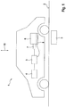
- FIGS. 1 and 2 show in purely schematic representations the vehicle 1 according to the invention, designed as a hybrid vehicle with inductive charging option.
- the vehicle 1 stands on a surface 2. In or below the surface 2 there is a primary coil 3 of an external charging device.
- the vehicle 1 comprises an electric machine 4, which is primarily arranged to drive the vehicle 1.
- a battery 5 is located in the vehicle 1 in order to supply the electrical machine 4 with electrical energy.
- an internal combustion engine 6 is arranged in the vehicle 1.
- the internal combustion engine 6 is drive-connected to a generator 7.
- the battery 5 can be charged via the internal combustion engine 6 and the generator 7.
- the vehicle 1 it is additionally or alternatively also possible to mechanically connect the internal combustion engine 6 to the wheels of the vehicle 1 in order to drive the vehicle 1 directly via the internal combustion engine 6. Furthermore, it is also possible instead of the generator 7, the to operate electric machine 4 via the internal combustion engine 6 as a generator.
- a secondary coil 8 is attached to the internal combustion engine 6 on the underside, that is to say the side of the internal combustion engine 6 facing the surface 2.
- the secondary coil 8 is connected to the battery 5 in an electrically conductive manner.
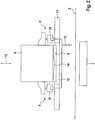
- FIG 2 shows the chassis 11 and an engine mount 9 for fastening the internal combustion engine 6 to the chassis 11.
- the engine mount 9 here comprises several individual engine mounts 10.
- the motor mounts 10 can be adjusted in height along a vertical axis 15 via a hydraulic system 13. This makes it possible to lower the internal combustion engine 6 together with the secondary coil 8 attached to it along the vertical axis 15.
- the internal combustion engine 6 is located in or above a free space 12 of the chassis 11, so that the internal combustion engine 6 can be lowered as far as possible.
- the secondary coil 8 is as close as possible to the primary coil 3, so that efficient, inductive charging of the battery 5 is possible.
- FIG. 2 shows, purely schematically, an oil pan 14 in the lower region of the internal combustion engine 6.
- the secondary coil 8 is preferably located directly under this oil pan 14.
Landscapes
- Engineering & Computer Science (AREA)
- Transportation (AREA)
- Mechanical Engineering (AREA)
- Power Engineering (AREA)
- Chemical & Material Sciences (AREA)
- Combustion & Propulsion (AREA)
- Electric Propulsion And Braking For Vehicles (AREA)
- Hybrid Electric Vehicles (AREA)
Description
- Vorliegende Erfindung betrifft ein Hybridfahrzeug mit einer induktiven Lademöglichkeit.
- Hier betrachtete Fahrzeuge umfassen sowohl eine elektrische Maschine zum Antreiben des Fahrzeugs als auch einen Verbrennungsmotor. Mit dem Verbrennungsmotor wird elektrische Energie zum Laden einer Batterie des Fahrzeugs erzeugt und/oder der Verbrennungsmotor wird direkt zum Antreiben des Fahrzeugs genutzt.
- Die Druckschrift
DE 10 2012 217 779 A1 zeigt solch ein Fahrzeug mit einer induktiven Lademöglichkeit für die Batterie. Dabei ist in oder unter der Oberfläche (beispielsweise einer Parkfläche) eine Primärspule vorgesehen. Im Fahrzeug befindet sich eine Sekundärspule. Bei ausreichend kleinem Abstand zwischen der Primärspule und der Sekundärspule kann relativ effizient elektrische Energie zum Laden der Batterie im Fahrzeug übertragen werden. Um einen möglichst kleinen Abstand zwischen den beiden Spulen beim Laden zu ermöglichen, wird inDE 10 2012 217 779 A1 vorgeschlagen, die Sekundärspule in der Karosserie des Fahrzeugs anzuordnen und beim Ladevorgang die gesamte Karosserie gegenüber dem Fahrwerk abzusenken. -
DE102011089339A1 zeigt ein Hybridfahrzeug mit einer separaten Einrichtung zum Absenken der Sekundärspule. -
DE 10 2014 018754 A1 zeigt ein Fahrzeug, bei dem die Sekundärspule in die Ölwanne eingebaut ist. - Es ist eine Aufgabe vorliegender Erfindung, ein Fahrzeug, insbesondere ein Hybridfahrzeug mit induktiver Lademöglichkeit, anzugeben, das auf einfache, wartungsarme und energieeffiziente Art ein Absenken des Sekundärspule ermöglicht.
- Die Lösung der Aufgabe erfolgt durch die Merkmale des Anspruchs 1. Die Unteransprüche haben vorteilhafte Ausgestaltungen der Erfindung zum Gegenstand.
- Somit wird die Aufgabe gelöst durch ein Fahrzeug. Bei dem Fahrzeug handelt es sich insbesondere um ein Hybridfahrzeug. Das Fahrzeug umfasst zumindest eine elektrische Maschine zum Antreiben des Fahrzeugs. Die elektrische Maschine dient in erster Linie als Elektromotor, kann jedoch in gewissen Fahrsituationen auch generatorisch betrieben werden. Ferner umfasst das Fahrzeug eine Batterie zur Versorgung der elektrischen Maschine mit elektrischer Energie.
- Im Fahrzeug befindet sich ein Verbrennungsmotor. Der Verbrennungsmotor kann insbesondere mit Benzin, Diesel oder Gas betrieben werden. Bei dem Verbrennungsmotor kann es sich um einen kleinen Verbrennungsmotor handeln, der lediglich als Range-Extender genutzt wird. In seiner Funktion als Range-Extender erzeugt der Verbrennungsmotor elektrische Energie zum Aufladen der Batterie und/oder zum Betreiben der elektrischen Maschine. Hierzu ist der Verbrennungsmotor mit einem Generator antriebsverbunden. Zusätzlich oder alternativ ist auch vorgesehen, dass der Verbrennungsmotor zum direkten, mechanischen Antreiben des Fahrzeugs genutzt wird und/oder die elektrische Maschine mittels des Verbrennungsmotors generatorisch betrieben wird.
- An der Unterseite des Verbrennungsmotors ist eine Sekundärspule befestigt. Der Einfachheit halber wird hier von einer Sekundärspule gesprochen. Tatsächlich kann es sich um eine Kombination mehrerer Spulen handeln. Die Sekundärspule ist elektrisch leitend mit der Batterie verbunden und für eine induktive Ladung der Batterie ausgebildet. Insbesondere ist vorgesehen, dass an einer Ladestation die Sekundärspule in die Nähe einer Primärspule gebracht wird. Die Primärspule befindet sich an oder in einer Oberfläche, beispielsweise der Straße oder einer Parkfläche. Durch Induktion kann von der Primärspule auf die Sekundärspule elektrische Energie zum Laden der Batterie im Fahrzeug übertragen werden. Zusätzlich zu der induktiven Lademöglichkeit, kann am Fahrzeug auch eine Möglichkeit zur kabelgebundenen Aufladung der Batterie vorgesehen sein.
- Das erfindungsgemäße Fahrzeug umfasst eine höhenverstellbare Motorlagerung zur Befestigung des Verbrennungsmotors an einem Fahrwerk des Fahrzeugs. Die Motorlagerung ist dazu ausgebildet, für einen Ladevorgang den Verbrennungsmotor samt Sekundärspule gegenüber dem Fahrwerk abzusenken.
- Erfindungsgemäß wird also ein ohnehin schon vorhandenes Element, nämlich die Motorlagerung, dazu genutzt, um die Sekundärspule abzusenken. Gleichzeitig wird darauf geachtet, dass ein relativ leichtes Bauteil, nämlich der Verbrennungsmotor und nicht die gesamte Karosserie abgesenkt wird. Dadurch ist der Absenkvorgang relativ energieeffizient und die beweglichen Teile der Lagerung müssen nur für das relativ geringe Gewicht ausgelegt werden.
- In bevorzugter Ausführung umfasst das Fahrwerk zumindest einen Achsträger. Der Achsträger kann auch als Fahrschemel oder Hilfsrahmen bezeichnet werden. Am Achsträger werden zwei gegenüberliegende Räder befestigt. Üblicherweise umfasst das Fahrzeug zwei Achsträger. Der Verbrennungsmotor ist vorzugsweise mittels der höhenverstellbaren Motorlagerung an einem der beiden Achsträger befestigt. Insbesondere weist der Achsträger einen Freiraum auf, durch den der Verbrennungsmotor nach unten abgesenkt werden kann.
- Die Motorlagerung setzt sich vorzugsweise aus zwei, insbesondere drei oder vier, einzelnen Motorlagern zusammen.
- Vorzugsweise ist vorgesehen, dass die Höhenverstellung der Motorlagerung hydraulisch, pneumatisch oder elektro-mechanisch erfolgt. Bei der hydraulischen oder pneumatischen Ausführung gibt es in der Motorlagerungen, insbesondere den einzelnen Motorlagern, sprechende Kammern, die vorzugsweise im normalen Betrieb des Fahrzeugs mit einem entsprechenden Druck gefüllt sind. Zum Absenken des Verbrennungsmotors wird der Druck aus diesen Kammern abgelassen. Bei der elektro-mechanischen Variante können entsprechende Elektromotoren zur Höhenverstellung des Verbrennungsmotors benutzt werden.
- Im Fahrzeug befindet sich vorteilhafterweise ein Steuergerät zur Ansteuerung der Höhenverstellung der Motorlagerung. Das Steuergerät kann beispielsweise vom Fahrer und/oder von der externen Ladevorrichtung entsprechende Signale erhalten, um die Höhenverstellung der Motorlagerung anzusteuern.
- Der Verbrennungsmotor weist üblicherweise eine Ölwanne auf. Die Sekundärspule ist insbesondere direkt unter der Ölwanne am Verbrennungsmotor befestigt. Sonders bevorzugt ist dabei vorgesehen, dass sich die Sekundärspule zwischen der Ölwanne und einer unter der Sekundärspule angeordneten Motorabschirmung befindet.
- Die Sekundärspule befindet sich möglichst nah am Verbrennungsmotor, sodass im normalen Betrieb des Fahrzeugs die Sekundärspule höher liegt als die gewünschte Bodenfreiheitslinie des Fahrzeugs.
- Weitere Einzelheiten, Merkmale und Vorteile der Erfindung ergeben sich aus der nachfolgenden Beschreibung und den Figuren. Es zeigen:
- Figur 1
- eine schematische Ansicht des erfindungsgemäßen Fahrzeugs, und
- Figur 2
- eine schematische Detailansicht des erfindungsgemäßen Fahrzeugs.
- Die
Figuren 1 und2 zeigen in rein schematischen Darstellungen das erfindungsgemäße Fahrzeug 1, ausgebildet als Hybridfahrzeug mit induktiver Lademöglichkeit. - Das Fahrzeug 1 steht auf einer Oberfläche 2. In oder unter der Oberfläche 2 befindet sich eine Primärspule 3 einer externen Ladevorrichtung.
- Das Fahrzeug 1 umfasst eine elektrische Maschine 4, die in erster Linie zum Antrieb des Fahrzeugs 1 angeordnet ist. Zur Versorgung der elektrischen Maschine 4 mit elektrischer Energie, befindet sich im Fahrzeug 1 eine Batterie 5.
- Des Weiteren ist im Fahrzeug 1 ein Verbrennungsmotor 6 angeordnet. Der Verbrennungsmotor 6 ist mit einem Generator 7 antriebsverbunden. Über den Verbrennungsmotor 6 und den Generator 7 kann die Batterie 5 aufgeladen werden.
- Je nach Ausgestaltung des Fahrzeugs 1, ist es zusätzlich oder alternativ auch möglich, den Verbrennungsmotor 6 mechanisch mit den Rädern des Fahrzeugs 1 zu verbinden, um so das Fahrzeug 1 direkt über den Verbrennungsmotor 6 anzutreiben. Des Weiteren ist es auch möglich, anstatt des Generators 7, die elektrische Maschine 4 über den Verbrennungsmotor 6 generatorisch zu betreiben.
- An der Unterseite, also der der Oberfläche 2 zugewandten Seite des Verbrennungsmotors 6 ist eine Sekundärspule 8 am Verbrennungsmotor 6 befestigt. Die Sekundärspule 8 ist mit der Batterie 5 elektrisch leitend verbunden.
-
Figur 2 zeigt das Fahrwerk 11 und eine Motorlagerungen 9 zur Befestigung des Verbrennungsmotors 6 am Fahrwerk 11. Die Motorlagerungen 9 umfasst hierbei mehrere einzelne Motorlager 10. - Im gezeigten Ausführungsbeispiel sind die Motorlager 10 über eine Hydraulik 13 entlang einer Hochachse 15 höhenverstellbar. Dadurch ist es möglich, den Verbrennungsmotor 6 samt der daran befestigten Sekundärspule 8 entlang der Hochachse 15 abzusenken. Insbesondere befindet sich der Verbrennungsmotor 6 in oder über einen Freiraum 12 des Fahrwerks 11, sodass der Verbrennungsmotor 6 möglichst weit abgesenkt werden kann.
- Im abgesenkten Zustand befindet sich die Sekundärspule 8 möglichst nahe an der Primärspule 3, sodass eine effiziente, induktive Ladung der Batterie 5 möglich.
-
Figur 2 zeigt rein schematisch eine Ölwanne 14 am unteren Bereich des Verbrennungsmotors 6. Die Sekundärspule 8 befindet sich vorzugsweise direkt unter dieser Ölwanne 14. -
- 1
- Fahrzeug
- 2
- Oberfläche
- 3
- Primärspule
- 4
- elektrische Maschine
- 5
- Batterie
- 6
- Verbrennungsmotor
- 7
- Generator
- 8
- Sekundärspule
- 9
- Motorlagerung
- 10
- Motorlager
- 11
- Fahrwerk
- 12
- Freiraum
- 13
- Hydraulik
- 14
- Ölwanne
- 15
- Hochachse
Claims (7)
- Fahrzeug (1), insbesondere Hybridfahrzeug mit induktiver Lademöglichkeit, umfassend• eine elektrische Maschine (4) zum Antreiben des Fahrzeugs (1),• eine Batterie (5) zur Versorgung der elektrischen Maschine (4),• einen Verbrennungsmotor (6) zum Erzeugen elektrischer Energie und/oder direktem Antreiben des Fahrzeugs (1),• eine an der Unterseite des Verbrennungsmotors (6) angeordnete Sekundärspule (8) für ein induktives Laden der Batterie (5), gekennzeichnet durch• eine höhenverstellbare Motorlagerung (9) zur Befestigung des Verbrennungsmotors (6) an einem Fahrwerk (11) des Fahrzeugs (1),• wobei die Motorlagerung (9) dazu ausgebildet ist, für einen Ladevorgang den Verbrennungsmotor (6) samt Sekundärspule (8) gegenüber dem Fahrwerk (11) abzusenken.
- Fahrzeug nach Anspruch 1, wobei das Fahrwerk (11) einen Achsträger zur Befestigung von zwei gegenüberliegenden Rädern umfasst, und wobei der Verbrennungsmotor (6) mittels der Motorlagerung (9) an dem Achsträger befestigt ist.
- Fahrzeug nach einem der vorhergehenden Ansprüche, wobei die Motorlagerung (9) zumindest zwei, vorzugsweise drei oder vier, einzelne Motorlager (10) umfasst.
- Fahrzeug nach einem der vorhergehenden Ansprüche, wobei die Motorlagerung (9) hydraulisch, pneumatisch oder elektro-mechanisch höhenverstellbar ist.
- Fahrzeug nach einem der vorhergehenden Ansprüche, wobei die Höhenverstellung der Motorlagerung (9) von einem Steuergerät des Fahrzeugs (1) ansteuerbar ist.
- Fahrzeug nach einem der vorhergehenden Ansprüche, wobei die Sekundärspule (8) unter einer Ölwanne (14) des Verbrennungsmotors (6) angeordnet ist.
- Fahrzeug nach Anspruch 6, wobei die Sekundärspule (8) zwischen der Ölwanne (14) des Verbrennungsmotors und einer unter der Sekundärspule (8) angeordneten Motorabschirmung angeordnet ist.
Applications Claiming Priority (2)
| Application Number | Priority Date | Filing Date | Title |
|---|---|---|---|
| DE102016217063.5A DE102016217063A1 (de) | 2016-09-08 | 2016-09-08 | Hybridfahrzeug mit induktiver Lademöglichkeit |
| PCT/EP2017/070477 WO2018046236A1 (de) | 2016-09-08 | 2017-08-11 | Hybridfahrzeug mit induktiver lademöglichkeit |
Publications (2)
| Publication Number | Publication Date |
|---|---|
| EP3509884A1 EP3509884A1 (de) | 2019-07-17 |
| EP3509884B1 true EP3509884B1 (de) | 2020-10-07 |
Family
ID=59626615
Family Applications (1)
| Application Number | Title | Priority Date | Filing Date |
|---|---|---|---|
| EP17752112.7A Active EP3509884B1 (de) | 2016-09-08 | 2017-08-11 | Hybridfahrzeug mit induktiver lademöglichkeit |
Country Status (4)
| Country | Link |
|---|---|
| EP (1) | EP3509884B1 (de) |
| CN (1) | CN109476223A (de) |
| DE (1) | DE102016217063A1 (de) |
| WO (1) | WO2018046236A1 (de) |
Families Citing this family (1)
| Publication number | Priority date | Publication date | Assignee | Title |
|---|---|---|---|---|
| CN114516263A (zh) * | 2022-03-09 | 2022-05-20 | 杭州德创电子股份有限公司 | 一种重卡换电的连接器气动安装装置 |
Citations (1)
| Publication number | Priority date | Publication date | Assignee | Title |
|---|---|---|---|---|
| DE102013214311A1 (de) * | 2013-07-22 | 2015-01-22 | Zf Friedrichshafen Ag | Ladevorrichtung zum Laden einer Batterie eines Fahrzeugs |
Family Cites Families (10)
| Publication number | Priority date | Publication date | Assignee | Title |
|---|---|---|---|---|
| DE102010054909A1 (de) * | 2010-12-17 | 2012-06-21 | Daimler Ag | Kraftfahrzeugvorrichtung mit einer Lade- und/oder Entladeeinheit |
| DE102011108546A1 (de) * | 2011-07-26 | 2013-01-31 | Daimler Ag | Vorrichtung und Verfahren zum Laden eines Energiespeichers eines Fahrzeuges |
| DE102011088112A1 (de) * | 2011-12-09 | 2013-06-13 | Bayerische Motoren Werke Aktiengesellschaft | Kraftwagen |
| DE102011089339A1 (de) * | 2011-12-21 | 2013-06-27 | Continental Automotive Gmbh | Induktives Übertragen von Energie von einer Primärspule zu einer Sekundärspule eines elektromobilen Kraftfahrzeugs |
| US9796280B2 (en) * | 2012-03-23 | 2017-10-24 | Hevo Inc. | Systems and mobile application for electric wireless charging stations |
| DE102012217779A1 (de) | 2012-09-28 | 2014-04-03 | Siemens Aktiengesellschaft | Ladesteuereinheit und Verfahren zur Einstellung eines Abstands für einen induktiven Ladevorgang |
| CN203193350U (zh) * | 2013-03-14 | 2013-09-11 | 安徽江淮汽车股份有限公司 | 一种电动汽车高耦合系数无线充电装置 |
| DE102013103157A1 (de) * | 2013-03-27 | 2014-10-02 | Dr. Ing. H.C. F. Porsche Aktiengesellschaft | Kontaktloses Aufladen eines elektrischen Energiespeichers eines Kraftfahrzeugs |
| KR101824578B1 (ko) * | 2013-04-26 | 2018-02-01 | 도요타 지도샤(주) | 수전 장치, 송전 장치, 전력 전송 시스템 및 주차 지원 장치 |
| DE102014018754A1 (de) * | 2014-12-16 | 2016-06-16 | Daimler Ag | Kraftfahrzeug mit einer Umhüllung für dessen Sekundärspule zum induktiven Laden einer kraftfahrzeugseitigen elektrischen Speichereinrichtung |
-
2016
- 2016-09-08 DE DE102016217063.5A patent/DE102016217063A1/de not_active Withdrawn
-
2017
- 2017-08-11 EP EP17752112.7A patent/EP3509884B1/de active Active
- 2017-08-11 CN CN201780044256.4A patent/CN109476223A/zh active Pending
- 2017-08-11 WO PCT/EP2017/070477 patent/WO2018046236A1/de not_active Ceased
Patent Citations (1)
| Publication number | Priority date | Publication date | Assignee | Title |
|---|---|---|---|---|
| DE102013214311A1 (de) * | 2013-07-22 | 2015-01-22 | Zf Friedrichshafen Ag | Ladevorrichtung zum Laden einer Batterie eines Fahrzeugs |
Also Published As
| Publication number | Publication date |
|---|---|
| DE102016217063A1 (de) | 2018-03-08 |
| WO2018046236A1 (de) | 2018-03-15 |
| EP3509884A1 (de) | 2019-07-17 |
| CN109476223A (zh) | 2019-03-15 |
Similar Documents
| Publication | Publication Date | Title |
|---|---|---|
| EP2398660B1 (de) | Verfahren und ladevorrichtung zum aufladen einer kraftfahrzeugbatterie | |
| EP2738069B1 (de) | Hilfsrahmen für ein Kraftfahrzeug | |
| EP3084919B1 (de) | Anordnung einer induktionsspule an einem unterboden eines kraftwagens | |
| DE102012025371B4 (de) | Kraftfahrzeug | |
| EP2788212B1 (de) | Kraftwagen | |
| DE102019118384A1 (de) | Mpe-achssatz mit gemeinsamer ecu | |
| DE102012217779A1 (de) | Ladesteuereinheit und Verfahren zur Einstellung eines Abstands für einen induktiven Ladevorgang | |
| DE102010016188A1 (de) | Verfahren zum Betreiben eines Elektrofahrzeuges | |
| DE102015217274A1 (de) | Verfahren zur induktiven Energieübertragung und Vorrichtung zum Betrieb einer induktiven Energieübertragungsvorrichtung | |
| DE102009028565A1 (de) | Vorrichtung zum Laden elektrisch angetriebener Fahrzeuge und Verfahren zum Betreiben der Vorrichtung | |
| DE102013003918B3 (de) | Vorrichtung aufweisend ein Fahrzeug und wenigstens eine Hochvoltbatterie sowie Verfahren für eine Vorrichtung | |
| DE102010038281A1 (de) | Energierekuperation aus einer Fahrzeugfederung | |
| DE102019111980A1 (de) | Energieversorgungseinheit für aktives fahrwerksystem | |
| DE102017103397A1 (de) | Achsantriebseinheit, Antriebsachse und Kraftfahrzeug | |
| DE102015008829A1 (de) | Trägerfahrzeug mit einem Zusatzfahrzeug | |
| EP3427992B1 (de) | Kühlfahrzeug | |
| DE102011108543A9 (de) | Ladevorrichtung zum induktiven Laden eines Fahrzeugs | |
| EP3509884B1 (de) | Hybridfahrzeug mit induktiver lademöglichkeit | |
| DE102012211516B4 (de) | Elektrisch angetriebenes Fahrzeug | |
| AT16612U1 (de) | Elektrisches Fahrzeug | |
| DE102011006665A1 (de) | Windkraftanlage und Verfahren zum Bewegen eines Generators relativ zu einem Getriebe innerhalb einer Gondel einer Windkraftanlage | |
| DE102019109550A1 (de) | Modularer Fahrzeugaufbau und Montageverfahren | |
| DE102023202044A1 (de) | Antriebsanordnung für ein Kraftfahrzeug | |
| DE102012208285B3 (de) | Energierückgewinnungssystem im Fahrzeug | |
| DE102020119127A1 (de) | Verfahren zum Betreiben eines Kraftfahrzeugs sowie entsprechendes Kraftfahrzeug |
Legal Events
| Date | Code | Title | Description |
|---|---|---|---|
| STAA | Information on the status of an ep patent application or granted ep patent |
Free format text: STATUS: UNKNOWN |
|
| STAA | Information on the status of an ep patent application or granted ep patent |
Free format text: STATUS: THE INTERNATIONAL PUBLICATION HAS BEEN MADE |
|
| PUAI | Public reference made under article 153(3) epc to a published international application that has entered the european phase |
Free format text: ORIGINAL CODE: 0009012 |
|
| STAA | Information on the status of an ep patent application or granted ep patent |
Free format text: STATUS: REQUEST FOR EXAMINATION WAS MADE |
|
| 17P | Request for examination filed |
Effective date: 20190220 |
|
| AK | Designated contracting states |
Kind code of ref document: A1 Designated state(s): AL AT BE BG CH CY CZ DE DK EE ES FI FR GB GR HR HU IE IS IT LI LT LU LV MC MK MT NL NO PL PT RO RS SE SI SK SM TR |
|
| AX | Request for extension of the european patent |
Extension state: BA ME |
|
| DAV | Request for validation of the european patent (deleted) | ||
| DAX | Request for extension of the european patent (deleted) | ||
| REG | Reference to a national code |
Ref country code: DE Ref legal event code: R079 Ref document number: 502017007643 Country of ref document: DE Free format text: PREVIOUS MAIN CLASS: B60K0006200000 Ipc: B60K0001040000 |
|
| RIC1 | Information provided on ipc code assigned before grant |
Ipc: B60L 53/12 20190101ALI20200323BHEP Ipc: B60K 6/20 20071001ALI20200323BHEP Ipc: H02J 50/10 20160101ALI20200323BHEP Ipc: B60L 53/38 20190101ALI20200323BHEP Ipc: H02J 7/02 20160101ALI20200323BHEP Ipc: B60L 53/34 20190101ALI20200323BHEP Ipc: B60L 53/39 20190101ALI20200323BHEP Ipc: H02J 50/90 20160101ALI20200323BHEP Ipc: H01F 38/14 20060101ALI20200323BHEP Ipc: B60K 1/04 20190101AFI20200323BHEP |
|
| GRAP | Despatch of communication of intention to grant a patent |
Free format text: ORIGINAL CODE: EPIDOSNIGR1 |
|
| STAA | Information on the status of an ep patent application or granted ep patent |
Free format text: STATUS: GRANT OF PATENT IS INTENDED |
|
| INTG | Intention to grant announced |
Effective date: 20200520 |
|
| GRAS | Grant fee paid |
Free format text: ORIGINAL CODE: EPIDOSNIGR3 |
|
| GRAA | (expected) grant |
Free format text: ORIGINAL CODE: 0009210 |
|
| STAA | Information on the status of an ep patent application or granted ep patent |
Free format text: STATUS: THE PATENT HAS BEEN GRANTED |
|
| AK | Designated contracting states |
Kind code of ref document: B1 Designated state(s): AL AT BE BG CH CY CZ DE DK EE ES FI FR GB GR HR HU IE IS IT LI LT LU LV MC MK MT NL NO PL PT RO RS SE SI SK SM TR |
|
| REG | Reference to a national code |
Ref country code: GB Ref legal event code: FG4D Free format text: NOT ENGLISH |
|
| REG | Reference to a national code |
Ref country code: CH Ref legal event code: EP Ref country code: AT Ref legal event code: REF Ref document number: 1320810 Country of ref document: AT Kind code of ref document: T Effective date: 20201015 |
|
| REG | Reference to a national code |
Ref country code: DE Ref legal event code: R096 Ref document number: 502017007643 Country of ref document: DE |
|
| REG | Reference to a national code |
Ref country code: IE Ref legal event code: FG4D Free format text: LANGUAGE OF EP DOCUMENT: GERMAN |
|
| REG | Reference to a national code |
Ref country code: NL Ref legal event code: MP Effective date: 20201007 |
|
| PG25 | Lapsed in a contracting state [announced via postgrant information from national office to epo] |
Ref country code: FI Free format text: LAPSE BECAUSE OF FAILURE TO SUBMIT A TRANSLATION OF THE DESCRIPTION OR TO PAY THE FEE WITHIN THE PRESCRIBED TIME-LIMIT Effective date: 20201007 Ref country code: GR Free format text: LAPSE BECAUSE OF FAILURE TO SUBMIT A TRANSLATION OF THE DESCRIPTION OR TO PAY THE FEE WITHIN THE PRESCRIBED TIME-LIMIT Effective date: 20210108 Ref country code: RS Free format text: LAPSE BECAUSE OF FAILURE TO SUBMIT A TRANSLATION OF THE DESCRIPTION OR TO PAY THE FEE WITHIN THE PRESCRIBED TIME-LIMIT Effective date: 20201007 Ref country code: PT Free format text: LAPSE BECAUSE OF FAILURE TO SUBMIT A TRANSLATION OF THE DESCRIPTION OR TO PAY THE FEE WITHIN THE PRESCRIBED TIME-LIMIT Effective date: 20210208 Ref country code: NO Free format text: LAPSE BECAUSE OF FAILURE TO SUBMIT A TRANSLATION OF THE DESCRIPTION OR TO PAY THE FEE WITHIN THE PRESCRIBED TIME-LIMIT Effective date: 20210107 |
|
| REG | Reference to a national code |
Ref country code: LT Ref legal event code: MG4D |
|
| PG25 | Lapsed in a contracting state [announced via postgrant information from national office to epo] |
Ref country code: ES Free format text: LAPSE BECAUSE OF FAILURE TO SUBMIT A TRANSLATION OF THE DESCRIPTION OR TO PAY THE FEE WITHIN THE PRESCRIBED TIME-LIMIT Effective date: 20201007 Ref country code: IS Free format text: LAPSE BECAUSE OF FAILURE TO SUBMIT A TRANSLATION OF THE DESCRIPTION OR TO PAY THE FEE WITHIN THE PRESCRIBED TIME-LIMIT Effective date: 20210207 Ref country code: LV Free format text: LAPSE BECAUSE OF FAILURE TO SUBMIT A TRANSLATION OF THE DESCRIPTION OR TO PAY THE FEE WITHIN THE PRESCRIBED TIME-LIMIT Effective date: 20201007 Ref country code: PL Free format text: LAPSE BECAUSE OF FAILURE TO SUBMIT A TRANSLATION OF THE DESCRIPTION OR TO PAY THE FEE WITHIN THE PRESCRIBED TIME-LIMIT Effective date: 20201007 Ref country code: SE Free format text: LAPSE BECAUSE OF FAILURE TO SUBMIT A TRANSLATION OF THE DESCRIPTION OR TO PAY THE FEE WITHIN THE PRESCRIBED TIME-LIMIT Effective date: 20201007 Ref country code: BG Free format text: LAPSE BECAUSE OF FAILURE TO SUBMIT A TRANSLATION OF THE DESCRIPTION OR TO PAY THE FEE WITHIN THE PRESCRIBED TIME-LIMIT Effective date: 20210107 |
|
| PG25 | Lapsed in a contracting state [announced via postgrant information from national office to epo] |
Ref country code: NL Free format text: LAPSE BECAUSE OF FAILURE TO SUBMIT A TRANSLATION OF THE DESCRIPTION OR TO PAY THE FEE WITHIN THE PRESCRIBED TIME-LIMIT Effective date: 20201007 Ref country code: HR Free format text: LAPSE BECAUSE OF FAILURE TO SUBMIT A TRANSLATION OF THE DESCRIPTION OR TO PAY THE FEE WITHIN THE PRESCRIBED TIME-LIMIT Effective date: 20201007 |
|
| REG | Reference to a national code |
Ref country code: DE Ref legal event code: R097 Ref document number: 502017007643 Country of ref document: DE |
|
| PG25 | Lapsed in a contracting state [announced via postgrant information from national office to epo] |
Ref country code: SM Free format text: LAPSE BECAUSE OF FAILURE TO SUBMIT A TRANSLATION OF THE DESCRIPTION OR TO PAY THE FEE WITHIN THE PRESCRIBED TIME-LIMIT Effective date: 20201007 Ref country code: LT Free format text: LAPSE BECAUSE OF FAILURE TO SUBMIT A TRANSLATION OF THE DESCRIPTION OR TO PAY THE FEE WITHIN THE PRESCRIBED TIME-LIMIT Effective date: 20201007 Ref country code: CZ Free format text: LAPSE BECAUSE OF FAILURE TO SUBMIT A TRANSLATION OF THE DESCRIPTION OR TO PAY THE FEE WITHIN THE PRESCRIBED TIME-LIMIT Effective date: 20201007 Ref country code: EE Free format text: LAPSE BECAUSE OF FAILURE TO SUBMIT A TRANSLATION OF THE DESCRIPTION OR TO PAY THE FEE WITHIN THE PRESCRIBED TIME-LIMIT Effective date: 20201007 Ref country code: RO Free format text: LAPSE BECAUSE OF FAILURE TO SUBMIT A TRANSLATION OF THE DESCRIPTION OR TO PAY THE FEE WITHIN THE PRESCRIBED TIME-LIMIT Effective date: 20201007 Ref country code: SK Free format text: LAPSE BECAUSE OF FAILURE TO SUBMIT A TRANSLATION OF THE DESCRIPTION OR TO PAY THE FEE WITHIN THE PRESCRIBED TIME-LIMIT Effective date: 20201007 |
|
| PLBE | No opposition filed within time limit |
Free format text: ORIGINAL CODE: 0009261 |
|
| STAA | Information on the status of an ep patent application or granted ep patent |
Free format text: STATUS: NO OPPOSITION FILED WITHIN TIME LIMIT |
|
| PG25 | Lapsed in a contracting state [announced via postgrant information from national office to epo] |
Ref country code: DK Free format text: LAPSE BECAUSE OF FAILURE TO SUBMIT A TRANSLATION OF THE DESCRIPTION OR TO PAY THE FEE WITHIN THE PRESCRIBED TIME-LIMIT Effective date: 20201007 |
|
| 26N | No opposition filed |
Effective date: 20210708 |
|
| PG25 | Lapsed in a contracting state [announced via postgrant information from national office to epo] |
Ref country code: AL Free format text: LAPSE BECAUSE OF FAILURE TO SUBMIT A TRANSLATION OF THE DESCRIPTION OR TO PAY THE FEE WITHIN THE PRESCRIBED TIME-LIMIT Effective date: 20201007 Ref country code: IT Free format text: LAPSE BECAUSE OF FAILURE TO SUBMIT A TRANSLATION OF THE DESCRIPTION OR TO PAY THE FEE WITHIN THE PRESCRIBED TIME-LIMIT Effective date: 20201007 |
|
| PG25 | Lapsed in a contracting state [announced via postgrant information from national office to epo] |
Ref country code: SI Free format text: LAPSE BECAUSE OF FAILURE TO SUBMIT A TRANSLATION OF THE DESCRIPTION OR TO PAY THE FEE WITHIN THE PRESCRIBED TIME-LIMIT Effective date: 20201007 |
|
| REG | Reference to a national code |
Ref country code: CH Ref legal event code: PL |
|
| PG25 | Lapsed in a contracting state [announced via postgrant information from national office to epo] |
Ref country code: MC Free format text: LAPSE BECAUSE OF FAILURE TO SUBMIT A TRANSLATION OF THE DESCRIPTION OR TO PAY THE FEE WITHIN THE PRESCRIBED TIME-LIMIT Effective date: 20201007 |
|
| REG | Reference to a national code |
Ref country code: BE Ref legal event code: MM Effective date: 20210831 |
|
| PG25 | Lapsed in a contracting state [announced via postgrant information from national office to epo] |
Ref country code: LI Free format text: LAPSE BECAUSE OF NON-PAYMENT OF DUE FEES Effective date: 20210831 Ref country code: CH Free format text: LAPSE BECAUSE OF NON-PAYMENT OF DUE FEES Effective date: 20210831 |
|
| PG25 | Lapsed in a contracting state [announced via postgrant information from national office to epo] |
Ref country code: IS Free format text: LAPSE BECAUSE OF FAILURE TO SUBMIT A TRANSLATION OF THE DESCRIPTION OR TO PAY THE FEE WITHIN THE PRESCRIBED TIME-LIMIT Effective date: 20210207 Ref country code: LU Free format text: LAPSE BECAUSE OF NON-PAYMENT OF DUE FEES Effective date: 20210811 |
|
| PG25 | Lapsed in a contracting state [announced via postgrant information from national office to epo] |
Ref country code: IE Free format text: LAPSE BECAUSE OF NON-PAYMENT OF DUE FEES Effective date: 20210811 Ref country code: BE Free format text: LAPSE BECAUSE OF NON-PAYMENT OF DUE FEES Effective date: 20210831 |
|
| P01 | Opt-out of the competence of the unified patent court (upc) registered |
Effective date: 20230427 |
|
| PG25 | Lapsed in a contracting state [announced via postgrant information from national office to epo] |
Ref country code: CY Free format text: LAPSE BECAUSE OF FAILURE TO SUBMIT A TRANSLATION OF THE DESCRIPTION OR TO PAY THE FEE WITHIN THE PRESCRIBED TIME-LIMIT Effective date: 20201007 |
|
| PG25 | Lapsed in a contracting state [announced via postgrant information from national office to epo] |
Ref country code: HU Free format text: LAPSE BECAUSE OF FAILURE TO SUBMIT A TRANSLATION OF THE DESCRIPTION OR TO PAY THE FEE WITHIN THE PRESCRIBED TIME-LIMIT; INVALID AB INITIO Effective date: 20170811 |
|
| REG | Reference to a national code |
Ref country code: AT Ref legal event code: MM01 Ref document number: 1320810 Country of ref document: AT Kind code of ref document: T Effective date: 20220811 |
|
| PG25 | Lapsed in a contracting state [announced via postgrant information from national office to epo] |
Ref country code: AT Free format text: LAPSE BECAUSE OF NON-PAYMENT OF DUE FEES Effective date: 20220811 |
|
| PG25 | Lapsed in a contracting state [announced via postgrant information from national office to epo] |
Ref country code: MK Free format text: LAPSE BECAUSE OF FAILURE TO SUBMIT A TRANSLATION OF THE DESCRIPTION OR TO PAY THE FEE WITHIN THE PRESCRIBED TIME-LIMIT Effective date: 20201007 |
|
| PG25 | Lapsed in a contracting state [announced via postgrant information from national office to epo] |
Ref country code: TR Free format text: LAPSE BECAUSE OF FAILURE TO SUBMIT A TRANSLATION OF THE DESCRIPTION OR TO PAY THE FEE WITHIN THE PRESCRIBED TIME-LIMIT Effective date: 20201007 |
|
| PG25 | Lapsed in a contracting state [announced via postgrant information from national office to epo] |
Ref country code: MT Free format text: LAPSE BECAUSE OF FAILURE TO SUBMIT A TRANSLATION OF THE DESCRIPTION OR TO PAY THE FEE WITHIN THE PRESCRIBED TIME-LIMIT Effective date: 20201007 |
|
| PGFP | Annual fee paid to national office [announced via postgrant information from national office to epo] |
Ref country code: DE Payment date: 20250731 Year of fee payment: 9 |
|
| PGFP | Annual fee paid to national office [announced via postgrant information from national office to epo] |
Ref country code: GB Payment date: 20250818 Year of fee payment: 9 |
|
| PGFP | Annual fee paid to national office [announced via postgrant information from national office to epo] |
Ref country code: FR Payment date: 20250821 Year of fee payment: 9 |