EP3509770B1 - Press brake tool engagement system - Google Patents
Press brake tool engagement system Download PDFInfo
- Publication number
- EP3509770B1 EP3509770B1 EP17768929.6A EP17768929A EP3509770B1 EP 3509770 B1 EP3509770 B1 EP 3509770B1 EP 17768929 A EP17768929 A EP 17768929A EP 3509770 B1 EP3509770 B1 EP 3509770B1
- Authority
- EP
- European Patent Office
- Prior art keywords
- tool
- magnetic
- tool body
- coupling
- tool holder
- Prior art date
- Legal status (The legal status is an assumption and is not a legal conclusion. Google has not performed a legal analysis and makes no representation as to the accuracy of the status listed.)
- Active
Links
Images















Classifications
-
- B—PERFORMING OPERATIONS; TRANSPORTING
- B21—MECHANICAL METAL-WORKING WITHOUT ESSENTIALLY REMOVING MATERIAL; PUNCHING METAL
- B21D—WORKING OR PROCESSING OF SHEET METAL OR METAL TUBES, RODS OR PROFILES WITHOUT ESSENTIALLY REMOVING MATERIAL; PUNCHING METAL
- B21D5/00—Bending sheet metal along straight lines, e.g. to form simple curves
- B21D5/02—Bending sheet metal along straight lines, e.g. to form simple curves on press brakes without making use of clamping means
- B21D5/0209—Tools therefor
- B21D5/0254—Tool exchanging
-
- B—PERFORMING OPERATIONS; TRANSPORTING
- B21—MECHANICAL METAL-WORKING WITHOUT ESSENTIALLY REMOVING MATERIAL; PUNCHING METAL
- B21D—WORKING OR PROCESSING OF SHEET METAL OR METAL TUBES, RODS OR PROFILES WITHOUT ESSENTIALLY REMOVING MATERIAL; PUNCHING METAL
- B21D37/00—Tools as parts of machines covered by this subclass
- B21D37/04—Movable or exchangeable mountings for tools
-
- B—PERFORMING OPERATIONS; TRANSPORTING
- B21—MECHANICAL METAL-WORKING WITHOUT ESSENTIALLY REMOVING MATERIAL; PUNCHING METAL
- B21D—WORKING OR PROCESSING OF SHEET METAL OR METAL TUBES, RODS OR PROFILES WITHOUT ESSENTIALLY REMOVING MATERIAL; PUNCHING METAL
- B21D5/00—Bending sheet metal along straight lines, e.g. to form simple curves
- B21D5/02—Bending sheet metal along straight lines, e.g. to form simple curves on press brakes without making use of clamping means
- B21D5/0209—Tools therefor
- B21D5/0236—Tool clamping
-
- B—PERFORMING OPERATIONS; TRANSPORTING
- B21—MECHANICAL METAL-WORKING WITHOUT ESSENTIALLY REMOVING MATERIAL; PUNCHING METAL
- B21D—WORKING OR PROCESSING OF SHEET METAL OR METAL TUBES, RODS OR PROFILES WITHOUT ESSENTIALLY REMOVING MATERIAL; PUNCHING METAL
- B21D55/00—Safety devices protecting the machine or the operator, specially adapted for apparatus or machines dealt with in this subclass
Definitions
- Press brake tool systems are used for forming sheet metal and other workpieces, and commonly include an upper table and a lower table.
- the upper table can be equipped to move vertically with respect to the lower table.
- Various forming tools can be mounted to the tables, so that when the tables are brought together, the tools bend or impress a workpiece, such as a piece of sheet metal, placed therebetween.
- the upper table will couple with male forming tools, such as press brake and punch tools, and the bottom table will couple with female forming tools, such as dies.
- male forming tools such as press brake and punch tools
- female forming tools such as dies.
- differently shaped press brake tools and dies are used.
- the forming tools mounted in the lower table are supported from below, they may be substituted with relative ease.
- the forming tools mounted to the upper table are suspended from above, usually held in place by a clamping mechanism that clamps all of the forming tools simultaneously.
- the forming tools mounted to the upper table may be removed by sliding the tools horizontally to an open end of the upper table, or in some instances, by removing the tools vertically.
- Horizontal exchange of the forming tools can be cumbersome due to the proximity of the forming tools with respect to one another in the upper table, often necessitating the removal of each tool mounted within the upper table when only one tool is being exchanged. Neighboring clamps may also interfere with horizontal removal of the tools.
- a safety tang that protrudes laterally from a surface of the forming tool. Such a safety tang may be shifted into a complementary groove defined by a tool holder in the upper table, thereby securing the tool to the holder until the tool is clamped.
- This mechanism is problematic, however, because of the manipulation required of the user to actuate the safety mechanism and secure the tool within the holder.
- Other preexisting safety mechanisms that involve forming tools equipped with a variety of latches, straps, or projections and complementary receiving spaces defined by tool holders are deficient for similar reasons. These designs typically employ a variety of movable external parts and often require a high degree of structural specificity between the design of each forming tool and corresponding tool holder.
- FR 2 791 590 A1 discloses the features of the first part of the independent claims. Further prior art is known from EP 1 479 461 A1 and EP 1 321 200 A2 .
- a tool includes a magnetic safety mechanism for operation in a press brake or similar machine apparatus.
- the mechanism includes a coupling assembly configured to provide a releasable magnetic coupling between the tool and a tool holder.
- a release is provided to selectively engage and disengage the magnetic coupling with the tool holder, alternately coupling and releasing the tool from the press assembly.
- a punch for a folding press or press brake with a top protrusion or tang that fits into a cavity in said press brake's upper tool holder, with a safety mechanism for temporarily holding said punch in said press brake using a switchable or adjustable permanent magnet assembly to urge or retain the punch upward into a holder receiving cavity for placement or staging until said holder is activated, thus clamping said punch solidly in place for use, the punch thus having a locked position where said punch is safely restrained in said punch holder, or an unlocked setting, where said punch can be manually installed in or removed from said punch holder.
- the safety mechanism where an assembly of permanent magnets and ferromagnetic parts are arranged to work cooperatively in a magnetic circuit, with some magnet(s) or part(s) made to be selectively moveable such that said magnetic circuit can be debilitated or weakened (as for punch installation or removal) or alternatively positioned so as to be optimized or enabled, to facilitate secure retention of punch in the holder until said holder is activated to clamp said punch solidly in the holder for folding operation.
- the safety mechanism where the magnetic assembly includes one or more electromagnets which could be switchable to selectively aid or conflict with the magnetic circuit, to effect retention or release of said punch.
- the safety mechanism where the magnetic assemblies consist of two or more parallel circuits of combinations of magnets and ferromagnetic parts such that one switchable or adjustable assembly is thus scalable for higher magnetic forces to compensation.
- the safety mechanism provided with a mechanism for directly leveraging or prying the punch away from the holder.
- the safety mechanism where one or more magnetic assemblies or permanent magnets are arranged along the length of a punch.
- the safety mechanism where such magnetic assembly or assemblies employs a bi-stable or non-momentary locked and unlocked state.
- the safety mechanism where the selectively moveable part or parts move slidably.
- the safety mechanism where the selectively moveable part or parts move rotatably.
- the safety mechanism provided with a mechanism for directly leveraging or prying the punch away from the holder.
- the safety mechanism where the magnets or magnetic assemblies are held in place with set-screws, glue, spring-pins, or such as are obvious variations of methods for securing said magnets or magnetic assemblies to the punch.
- the safety mechanism where the magnet or magnets are installed in the punch shoulder or tang with additionally assembly features.
- the safety mechanism with a selectable mechanism for dissipating magnetic flux away from the productive magnetic circuit by introducing a magnet or magnets or ferromagnetic part or parts to diverge some of the flux away from assisting in the punch-holding work of the magnetic circuit thus providing a selectably locked and unlocked state.
- a press brake tool comprising: a tool body having a working end configured for operation on a workpiece and a coupling end configured for selective engagement with a tool holder, the working end disposed generally opposite the coupling end; a magnetic assembly comprising one or more magnetic elements configured to generate a magnetic flux coupling adapted for the selective engagement of the coupling end of the tool body with the tool holder; and a coupling mechanism configured to manipulate at least one of the magnetic elements to modulate a strength of the magnetic flux coupling, where the coupling mechanism is adapted for selective disengagement of the coupling end of the tool body from the tool holder.
- the press brake tool further comprising a tang formed on the coupling end of the tool body and adapted for the selective engagement with the tool holder, where the magnetic assembly is configured to generate the magnetic flux coupling between the tang and a magnetic component of the tool holder.
- the press brake tool where the magnetic assembly comprises one or more permanent magnets disposed in the tang and configured to generate the magnetic flux coupling with the tool holder through one or both of a top surface and a side surface of the tang.
- the press brake tool, where the coupling mechanism comprise a magnetic armature configured to modulate the strength of the magnetic flux coupling by relative motion with respect to the one or more permanent magnets.
- the press brake tool where the relative motion comprises transverse location of the armature with respect to the one or more permanent magnets.
- the press brake tool further comprising a pushbutton type biasing member configured to retain the armature in alternate locked and unlocked positions, where the coupling end of the tool body is selectively engaged with and disengaged from the tool holder, respectively.
- the press brake tool where the relative motion comprises rotation of the magnetic armature with respect to the one or more permanent magnets.
- the press brake tool further comprising gear member configured for rotation of the armature between alternate locked and positions, where the coupling end of the tool body is selectively engaged with and disengaged from the tool holder, respectively.
- the press brake tool further comprising a pushbutton coupled to the gear member via a rack and pinion assembly and adapted for rotation of the armature thereby.
- the press brake tool further comprising a lever coupled to the armature for rotation thereof.
- the press brake tool where the armature comprises transversely oriented magnetic elements configured for selective interaction with corresponding transversely oriented permanent magnets in the tang.
- the press brake tool where the transversely permanent magnetics in the tang are adapted to generate the magnetic flux coupling through top surface and the side surface of the tang, respectively.
- a machine tool comprising: a first end configured for operation on a workpiece; a second end configured for engagement with a tool holder; a plurality of magnetic elements configured to generate magnetic flux couplings adapted for the engagement of the second end of the tool body with the tool holder; and a coupling mechanism configured to modulate the magnetic flux couplings, where the second end of the tool body is selectively disengaged from the tool holder.
- the machine tool where the coupling mechanism comprises first and second magnetic armatures joined together by a transverse member.
- the machine tool where first and second magnetic armatures have transversely oriented magnetic components.
- the machine tool, where the first and second magnetic armatures are configured for modulating the magnetic flux coupling by selective interaction with different respective permanent magnet elements disposed in the second end of the machine tool.
- the machine tool, where the different permanent magnet elements are disposed to generate the magnetic flux coupling through a top surface and one or more side surfaces of the second end of the machine tool, respectively.
- the machine tool further comprising a magnetically permeable material disposed adjacent at least one of the magnetic elements and adapted to substantially magnetically isolate the at least one elements from others of the magnetic elements.
- the machine tool where the magnetically permeable material is disposed adjacent a first set of the magnetic elements disposed to generate a first component of the magnetic flux couplings through a top surface of the second end of the machine tool, substantially isolated from a second set of the magnetic elements disposed to generate a second component of the magnetic flux couplings through at least one side surface of the second end of the machine tool.
- the machine tool further comprising one or more magnetic gaps disposed adjacent at least one of the plurality of magnetic elements, the magnetic gaps adapted to modulate at least one of the magnetic flux couplings by manipulation of the coupling mechanism with respect thereto.
- Suitable press brake tool systems can include a tool body having a working end configured for operation on a workpiece and a coupling end configured for selective engagement with a tool holder, the working end spaced from the coupling end along the tool body; and one or more magnetic elements configured to induce a magnetic coupling between the tool body and the tool holder, where the coupling end of the tool body is magnetically engageable with the tool holder.
- the magnetic elements can include one or more magnets disposed in the tool body for generating magnetic flux to induce the magnetic coupling, one or more ferromagnetic elements disposed in the tool body for guiding magnetic flux to induce the magnetic coupling, or a combination thereof.
- the magnetic coupling can be sufficient to support a weight of the tool body upon engagement of the coupling end with the tool holder.
- the press brake tool systems include a mechanism configured for selective disengagement of the coupling end of the tool body from the tool holder.
- the mechanism comprises an actuator engaged with the tool body, the actuator configured to urge at least a portion of the coupling end from the tool holder to define an air gap therebetween.
- the strength of the magnetic flux coupling can secure tool 10 even during operation on a workpiece without additional clamping support.
- FIG. IB is a front view of tool 10. As illustrated in FIG. IB, magnetic assemblies 18 may protrude a distance above top surface 20. The distance by which magnetic assemblies 18 protrude above top surface 20 may vary.
- Press brake tool system or apparatus 10 includes a tool body 21 with a working end configured for operation on a workpiece, and a coupling end configured for selective engagement with a tool holder.
- the working end is spaced from the coupling end along the tool body, e.g. at opposite top and bottom ends.
- One or more magnetic assemblies 18 can be configured to induce a magnetic coupling between the tool body 21 and the tool holder, where the coupling end of the tool body is magnetically engageable with the tool holder.
- the magnetic assemblies 18 can include one or more magnets disposed in the tool body 21 for generating magnetic flux to induce the magnetic coupling, one or more ferromagnetic components disposed in the tool body 21 for guiding magnetic flux to induce the magnetic coupling, or a combination thereof.
- the magnetic coupling is sufficient to support the weight of the tool body 21 upon engagement of the coupling end with the tool holder.
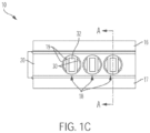
- FIG. 1 C is a top view of tool 10, showing each of the three magnetic assemblies 18 included in this particular example.
- each magnetic assembly 18 may include two assembly slugs 30 laterally flanking each side of an end guide 32. Assembly slugs 30 and end guide 32, along with other components of each magnetic assembly 18, may be contained within a housing 19, which can be fixed within tool 10. In some examples, such components may be cast or mold into housing 19 to form each magnetic assembly 18.
- Housing 19 may be a structural insert that defines the external shape of each magnetic assembly 18 and its internal compartments. Such an insert may be made from various materials including but not limited to one or more plastics or polymer compositions.
- each assembly slug 30 may be made from various materials including but not limited to a magnetically permeable material, e.g., one or more metals such as steel. In some examples, such magnetically permeable material may be highly permeable.
- End guides 32 may also be made from various materials including but not limited to iron or steel, e.g., electrical steel.
- FIG. 1C also shows line A-A, which denotes a cross-sectional plane used for illustration purposes.
- FIG. ID is an alternate top view of tool 10, showing three magnetic assemblies 18 exposed at one end through top surface 20.
- FIG. ID also shows line B-B, which denotes a cross-sectional plane, and detail K, used for illustration purposes.
- the magnetic assemblies 18 can include one or more permanent magnets disposed in the tool body 21, and configured to form a magnetic coupling between the tool body and the tool holder with the coupling end of the tool body 21 is engaged.
- One or more non-ferromagnetic components can also be disposed in the tool body, and adapted for modulation of a flux path through the one or more magnetic elements (e.g., where the strength of the magnetic coupling is responsive to the modulation of the flux path).
- a plurality of magnetic sub-assemblies 18 may each include one or more magnets, ferromagnetic elements or non-ferromagnetic components configured to independently induce a magnetic coupling between the coupling end of the tool body 21 and the tool holder.
- a tang 13 can be defined by the coupling end of the tool body, and adapted for the selective engagement with the tool holder.
- One or more magnets or ferromagnetic components can be disposed in the tang 13, and configured to induce the magnetic coupling by generating or guiding magnetic flux between the tang 13 and the tool holder.
- One or more load-bearing shoulders 16, 17 can be defined on the tool body, and configured to bear a mechanical load between the tool holder and the tool body for operation of the working end of the tool body 21 on a workpiece.
- One or more magnets or ferromagnetic components can also be disposed in the load-bearing shoulder 16, 17, and configured to induce the magnetic coupling by generating or guiding magnetic flux between the load-bearing shoulder 16, 17 and the tool holder.
- FIG. IE is a section view of tool 10, taken along line A-A of FIG. 1C .
- This section view illustrates the inner portion of a magnetic assembly 18 and armature 24 inserted therethrough, each component positioned within tool 10.
- magnetic assembly 18 can include an assembly magnet 34, multiple end guides 32 and a return flux guide or loop component 38, each contained within housing 19.
- Armature 24 can include an armature magnet 36.
- FIG. IE also shows an outline of the bottom portion of an exemplary tool holder TH (dashed lines) with which tool 10 is magnetically coupled and clamped into a press brake machine or similar machine apparatus.
- tool holder TH can be a preexisting, conventional tool holder lacking discrete magnetic components and made of steel, for example.
- assembly magnet 34 may comprise a permanent magnet made from one or more magnetic materials, e.g., neodymium iron boron ("NdFeB"). Assembly magnet 34 may be a bar magnet.
- NdFeB neodymium iron boron
- armature magnet 36 is included within armature 24 and positioned beneath assembly magnet 34 when armature 24 is inserted within lateral cavity 22.
- armature magnet 36 may also be a permanent magnet made of NdFeB.
- armature magnet 36 may be made of other magnetic materials. Armature magnet 36 may be magnetized diametrically and oriented such that the north pole of armature magnet 36 is in closest proximity to the south pole of assembly magnet 34.
- end guides 32 are positioned above assembly magnet 34, and between assembly magnet 34 and armature magnet 36.
- end guides 32 may be made from various materials including but not limited to one or more metals, e.g., iron or electrical steel.
- Return flux guide 38 is positioned beneath armature magnet 36 in this example, and is also contained within housing 19 as a sub-component of magnetic assembly 18.
- Return flux guide 38 may comprise a magnetically permeable material. In some examples, such material may be highly permeable.
- magnetic assembly 18 extends downward through tang 13 and into a vertical cavity 39 defined by tool body 21 to a distance below the horizontal plane of shoulders 16, 17.
- the distance by which each vertical magnetic assembly 18 extends within tool 10 may vary and may depend on the shape, weight, and/or size of tool 10, the number of magnetic assemblies 18 included within a given tool 10, and/or the configuration of the tool holder into which tool 10 is inserted.
- an air gap 33 may be defined beneath the bottom-most surface of flux guide 38 in magnetic assembly 18, at the bottom of vertical cavity 39.
- gap 33 may contribute to a desired magnetic flux direction induced by tool 10 and the holder by providing a non-ferromagnetic component positioned to modulate the magnetic flux coupling, e.g., by guiding the magnetic flux or by modifying or disrupting the flux path.
- FIG. IF is a top view of a vertical magnetic assembly 18, taken at detail K in FIG. ID. Detail K illustrates a magnified view of the top of each magnetic assembly 18.
- each magnetic assembly may include two D-shaped assembly slugs 30 and an end guide 32 exposed at top surface 20. Housing 19, also visible at top surface 20, may laterally partition assembly slugs 30 and end guide 32.
- FIG. 1G is a section view of detail H taken along section A-A.
- assembly magnet 34 may define an approximately rectangular cross-sectional shape
- armature magnet 36 may define an approximately circular cross-sectional shape.
- the shape of each magnet may vary.
- the cross-sectional width of each wall of housing 19 may also vary. In this particular embodiment, the cross-sectional width of each exterior wall of housing 19 may be the greatest near top surface 20.
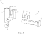
- FIG. 2 is an exploded view of a magnetic assembly 18 and armature 24.
- magnetic assembly 18 defines an aperture 40 configured to slidably receive armature 24 such that magnetic assembly 18 and armature 24 intersect.
- aperture 40 may define a lateral through-hole.
- Aperture 40 may align with lateral cavity 22 of tool 10, such that armature 24 is configured to slide seamlessly through aperture 40 and tool 10.
- the sub-assemblies of magnetic assembly 18 and armature 24 may include numerous distinct components.
- assembly magnet 34, return flux guide 38, each end guide 32, and each assembly slug 30 may be separate sub-components of each magnetic assembly 18, arranged to generate a magnetic circuit upon assembly with armature 24 and insertion within a tool holder.
- Housing 19 may define one or more internal compartments for containing each of the internal components of magnetic assembly 18. In this embodiment, housing 19 is cylindrical, but the shape of housing 19 may vary in other examples.
- Each armature 24 can include a plurality of dynamic elements, such as armature magnets 36, which can be permanent magnets in various embodiments.
- armature 24 includes three armature magnets 36 each flanked by a pair of D-shaped armature slugs 31.
- the armature slugs 31 can comprise ferromagnetic wedges. When inserted within tool 10, armature magnets 36 and slugs 31 can align with the magnetic elements included within each magnetic assembly 18.
- armature 24 can include one or more permanent magnets, electromagnets, ferromagnetic components, and/or non-ferromagnetic components collectively arranged to strengthen or support a magnetic circuit between tool 10 and the holder.
- Armature 24 may further include an end portion 42 that may be manually engaged by a user of tool 10 to insert and remove armature 24 therefrom.
- end portion 42 may comprise a handle, knob, protrusion, or other feature graspable by a user.
- FIG. 3A is a section view of tool 10, taken along line B-B of FIG. ID.
- tool 10 may define an internal lateral cavity 22 configured to slidably receive armature 24.
- a bias member 46 e.g., a spring, may be secured at a stop end 48 of cavity 22, protruding laterally within cavity 22 such that armature 24 contacts bias member 46 upon insertion into cavity 22.
- Cavity 22 may define a receiving end 50 positioned opposite stop end 48.
- Receiving end 50 may define a greater cross-sectional height and/or width to accommodate armature end portion 42.
- assembly slugs 30 may be laterally partitioned from each end guide 32, assembly magnet 34, armature magnet 36, and flux guide 38 by housing 19.
- An assembly slug 30 and armature slug 31, in combination, may extend vertically from top surface 20 to the top plane of flux guide 38.
- Armature 24 may be inserted to various depths within cavity 22.
- the depth at which armature 24 is inserted may determine whether tool 10 is in an engaged, locked position or a disengaged, unlocked position.
- movement of armature 24 can switch the strength of the magnetic flux coupling between two bi-stable states: an engaged state in which the magnetic flux coupling between tool 10 and the holder is established, and a disengaged state in which the magnetic flux coupling between tool 10 and the holder is diminished or absent.
- FIG. 3A depicts the locked position, in which armature 24 contacts, but may not compress, bias member 46. Accordingly, the locked position may represent a relaxed position.
- armature 24 functions as a button that can be manually pressed to various depths within cavity 22 by exerting various amounts of lateral force against armature end portion 42. As shown in the locked position of FIG. 3A , armature end portion 42 is inserted within cavity 22 such that its end surface is flush with the end surface of tool 10.
- magnetic circuit involves the shoulders of the tool holder: first to hold tool 10 firmly against such shoulders so that tool 10 is in an ideal position for clamping by a press brake or similar machine apparatus, and secondly because the gap between the tang 13 and the inside of the holder is designed as clearance and may therefore not be a precise or sufficiently small gap that it could be depended upon to form a reliable part of the magnetic circuit.
- magnetic flux 52 may be guided back down into each assembly slug 30, which, together with each armature slug 31, may function as a ferromagnetic wedge that propagates magnetic flux 52 downward through each magnetic assembly 18.
- magnetic flux 52 may loop horizontally, via return flux guide 38, and back upward through the south pole of armature magnet 36.
- air gaps 33 and 56 may be present at the bottom of each vertical aperture 39 and receiving end 50, respectively. Gaps 33 and 56 may function as non-ferromagnetic gaps to prevent magnetic flux 52 from dissipating within body 21 of tool 10 beneath vertical aperture 39 and receiving end 50, thereby maintaining an upward flux direction.
- FIG. 3A also shows that the body of armature 24 may be made from aluminum. In other examples, the body of armature 24 may be made from various different and/or additional materials. In this example, each flux guide 38 is made from a high permeability soft magnetic material. Other magnetic materials may also be suitable, depending upon flux density and other application-specific considerations.
- FIG. 3B is a section view of tool 10 in an unlocked configuration, taken along line B-B of FIG. ID.
- armature 24 may be urged a greater distance within lateral cavity 22, thereby compressing bias member 46.
- the magnetic poles of each assembly magnet 34 and armature magnet 36 are misaligned, creating a conflicting, and therefore much weaker, magnetic circuit.
- the reduced flux 52 generated within such a circuit may reduce the holding force between tool 10 and a corresponding tool holder, allowing manual insertion and removal of tool 10 with respect to the holder.
- gravity alone may cause tool 10, in the unlocked configuration, to fall from a corresponding tool holder.
- the release mechanism can include any suitable armature 24 having one or more magnets or ferromagnetic components 36 configured to modulate a strength of the magnetic coupling by motion with respect to the flux path defined by disposition of the one or more magnetic elements 34 in the tool body.
- the armature 24 can rotate the magnets or ferromagnetic components 36 with respect to the flux path, or with respect to the poles of the magnetic elements 34 defining the flux path.
- the armature 24 can also be configured for lateral motion of the one or more magnets or ferromagnetic components 36 with respect to the magnetic elements 24 and the flux path defined by the magnetic elements 34.
- a lever, knob or push button actuator can be engaged with the tool body 21, and mechanically coupled to the magnetic armature 24 for manipulation of the magnets or ferromagnetic elements 36 by the user to modulate the strength of the magnetic coupling.
- the release mechanism may also comprise a plurality of armature members 24, each having one or more of the magnets or ferromagnetic elements 36 configured to modulate the strength of the magnetic coupling by rotational or lateral motion with respect to one or more flux paths defined by disposition of the one or more magnetic elements 34 of the magnetic assembly 18 within the tool body 21.
- FIG. 4 is an isometric view of an upper portion of tool 60 for a press brake or similar machine apparatus.
- tool 60 may include a t-shaped magnetic circuit assembly with a sliding armature.
- the example of FIG. 4 includes two top magnets 62 included within tang 71. A portion of each top magnet 62 may be exposed at the top surface 65 of tool 60.
- Tool 60 further includes side magnets 64 within tang 71 , each exposed at reference face 66.
- Top and side magnets 62, 64 can be fixed within tool 60. Each top magnet 62 may be vertically oriented such that its north pole is positioned above its south pole. In some examples, top magnet 62 may be arranged in the opposite polar orientation. Each side magnet 64 may be oriented such that its north pole is positioned on the left side and its south pole on the right side, or vice versa. With respect to the magnetic orientation of top magnets 62, side magnets 64 may thus be oriented in an opposing orientation. Regardless of the specific polar orientation, each side magnet 64 may include a magnetic pole facing the exterior of tool 60, and a magnetic pole facing the interior of tool 60. In any or all of the various examples included herein, the polar orientation of each magnet may be reversed, provided that the polarity of each magnet relative to the other magnets comprising the magnetic circuit remains the same.
- Armature 68 can provide a coupling mechanism configured to modulate the strength of the magnetic flux coupling between tool 60 and the holder.
- Armature 68 is shown inserted within parallel lateral cavities defined by tool 60.
- tool 60 includes two lateral cavities: an upper cavity 70 positioned above a lower cavity 72.
- First or upper arm 74 of armature 68 may be slidably inserted into upper cavity 70, and second arm 76 may be slidably inserted into lower cavity 72.
- First arm 74 and second arm 76 may be connected at one end by a vertical or transverse armature member 77. While the particular arrangement of upper cavity 70 and/or lower cavity 72 may vary, FIG.
- upper cavity 70 may be defined within tang 71
- lower cavity 72 may be defined below the plane of shoulders 73, 75 that demarcate the lower boundary of tang 71.
- the exterior surface of transverse member 77 may remain accessible upon insertion of armature 68 within tool 60 such that transverse member 77 may be manually engaged by a user to insert armature 68 within tool 60, and to adjust the lateral depth at which armature 68 extends into tool 60.
- Upper arm 74 and lower arm 76 of armature 68 can each include one or more dynamic or moving elements, which may include permanent magnets and/or ferromagnetic components.
- a bias member 78 may be secured to a stop end 80 defined by lower cavity 72.
- bias member 78 comprises a spring.
- bias member 78 may not be compressed, or may be only slightly compressed, by second arm 76 of armature 68.
- Tool 60 also includes two vertical cavities 81. In some examples, the number of vertical cavities may vary and may depend on the number of top magnets 62 needed to form a magnetic circuit with armature 68 strong enough to at least temporarily secure tool 60 within a tool holder.
- Adjusting the position of armature 68 can modulate the strength of the magnetic flux coupling between tool 60 and the holder. For example, inserting armature 68 to a greater depth within tool 60 by compressing bias member 78 can cause misalignment between the magnetic poles of the dynamic elements of the armature and the magnetic poles of the top magnets 62 and side magnets 64, thus disrupting the magnetic flux coupling between tool 60 and the holder and allowing for release of the tool.
- armature 68 when the magnetic elements included in armature 68 are magnetically aligned with top and side magnets 62, 64 fixed within tool 60, a magnetic circuit can be established, thereby inducing a magnetic flux guided from tang 71 through reference face 66 into a ferromagnetic shoulder portion of a tool holder coupled with tool 60. Sliding armature 68 in this manner can gradually modulate the strength of the magnetic flux coupling between tool 60 and the holder.
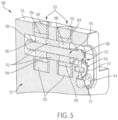
- FIG. 5 is an isometric section view of a tool 100 for a press brake or similar machine apparatus, taken along the length or longitudinal direction of tool 100.
- Tool 100 may include a cross-shaped circuit assembly with a rotating armature.
- tool 100 includes two vertical magnetic assemblies 101 , each assembly 101 including a first magnet 102 and a second magnet 103.
- First magnet 102 may be exposed at top surface 115, positioned above a lateral cavity 105 defined by tool 100.
- Second magnet 103 may be positioned below lateral cavity 105.
- focal wedges 104 may be sandwiched between each first magnet 102 and lateral cavity 105, as well as between each second magnet 103 and lateral cavity 105.
- tool 100 may also include an upper gear member 108, which includes an elongate body 109 that extends through at least a portion of lateral cavity 105.
- Upper gear member 108 may rotatably engage an adjacent pinion 110 via a plurality of complementary grooves, or mechanical teeth, protruding outward from the perimeter of both gear member 108 and pinion 110.
- pinion 110 and gear member 108 comprise gear assembly 112.
- An idler gear 111 may be also positioned at the radial center of pinion 110.
- Pinion 110 may rotatably engage rack 114 via a plurality of complementary grooves or mechanical teeth also protruding from rack 114.
- lateral movement of rack 114 may drive rotation of armature 116.
- lateral movement of rack 114 may cause pinion 110 to rotate, thereby causing rotation of upper gear member 108.
- body 109 of upper gear member 108 is secured within the radial center of each disc magnet 106, rotation of body 109 also drives rotation of each disc magnet 106, thereby adjusting the polarity of each disc magnet 106 with respect to first magnets 102 and second magnets 103.
- FIG. 6 is an isometric section view taken along the width of tool 100, transverse to the view of FIG. 5 .
- tool 100 may include one or more side magnets 118, 119.
- a lateral focal wedge 120 may be sandwiched between each side magnet 118, 119 and disc magnet 106.
- disc magnet 106 is magnetized axially such that it includes four magnetic poles.
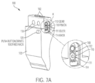
- FIG. 7A is an isometric view of tool 100.
- tool 100 may include an exterior button 122.
- button 122 protrudes outward from front surface 123, where it may be manually engaged by a user, for example.
- armature 116 thereby either releasing or locking tool 100 within a corresponding tool holder
- button 122 may be pushed.
- Pushing button 122 causes rack 114 to move laterally, thus causing pinion 110 and upper gear member 108 to rotate.
- Disc magnets 106 secured to gear member 106 may then be rotated, causing a shift in magnetic alignment within tool 100.
- FIG. 7B is a front view of tool 100. As shown in FIG. 7B , each first magnet 102 may protrude above the plane defined by top surface 115. Button 122 is positioned beneath tang 125, within body 107 of tool 100.
- FIG. 7C is a top view of tool 100.
- FIG. 7D is an alternate top view of tool 100, showing section B-B.
- a first set of magnets 102 may be exposed at top surface 115.
- This particular embodiment includes two vertical magnetic assemblies 101. In other examples, the number, size, and/or arrangement of magnetic assemblies 101 may vary.
- Button 122 is shown protruding laterally outward from tool 100.
- FIG. 7C also shows line A-A, which denotes a cross-sectional plane used for illustration purposes.
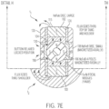
- FIG. 7E is a section view of detail H, taken along section A-A of FIG. 7C .
- tool assembly 100 With button 122 in a relaxed position, tool assembly 100 is in a locked or engaged configuration with respect to the tool holder. In the locked position, tool assembly 100 may form two magnetic circuits comprised of separate pathways of magnetic flux: flux pathway fi and flux pathway f 2 .
- flux pathway fi is guided in a counterclockwise direction through disc magnet 106 to first magnet 102, through top surface 115 of tang 125 into a ferromagnetic portion of a tool holder TH, and back through one of side magnets 118.
- the altemating magnetic poles of disc magnet 106, top magnet 102, and side magnet 118 in this configuration may generate the closed magnetic circuit defined by flux pathway f 2 .
- flux pathway f 2 is generated by the alternating magnetic poles of disc magnet 106, side magnets 118, and second magnet 103. As shown in the figure, flux pathway f 2 may be guided in a clockwise direction, passing from disc magnet 106 to second magnet 103, through a ferromagnetic shoulder portion of a tool holder TH, and back through side magnet 118.
- flux pathways fi and f 2 may generate a strong upward force to at least temporarily secure tool 100 within a corresponding tool holder.
- tool 100 may drive a magnetic flux through a larger portion of tool holder TH relative to other tool and punch designs.
- first magnet 102 may be an NdFeB disc, which may also be large, while side magnets 118 may be smaller, axially magnetized NdFeB discs.
- Disc magnet 106 may also be an NdFeB magnet.
- Disc magnet 106 may be magnetized radially.
- Focal wedges 104 and lateral focal wedges 120 may each be made of iron-nickel compositions in one example.
- FIG. 7F is a section view of tool 100, taken along section A-A of FIG. 7C .
- FIG. 7F shows tool 100 in a release position caused by pressing button 122.
- pressing button 122 causes disc magnet 106 to rotate.
- disc magnet 106 will rotate up to about 90°.
- Armature 116 may resist the rotation of disc magnet 106 beyond 90° such that no internal bias member, e.g., spring, may be necessary.
- a bias member may be included to prevent over-rotation of armature 116.
- non-ferromagnetic sleeves 124 may house magnetic assemblies 101 and side magnets 118 within tool 100.
- FIG. 8E is a section view of tool 60 taken along line B-B of FIG. 8B .
- FIG. 8E shows tool 60 in a release, or unlocked, configuration in which handle 85 has been slid or otherwise urged to the left and bias member 78 is at least partially compressed, causing the magnets 34, 36 to misalign with side magnets 64, thus weakening the magnetic flux coupling between tool 60 and its corresponding tool holder.
- movement of armature 68 directly corresponds to movement of handle 85.
- FIG. 9E is a section view of tool 130, taken along line A-A of FIG. 9D .
- top magnet 134 may be housed within a non-ferromagnetic housing or sleeve 135.
- Sleeve 135 may be made from various materials, including but not limited to aluminum or brass.
- Each of top magnet 134 and bottom magnet 136 may be an NdFeB magnet.
- Top magnet 134 may be axially magnetized, while bottom magnet 136 may be diametrically magnetized.
- each air gap 137, 138, 140 may comprise a lateral through-hole.
- Tool 130 may be inserted into tool holder TH.
- FIG. 9F is a section view of tool 130 at detail H, taken along line A-A of FIG. 10D.
- FIG. 9F shows magnetic flux F that may be generated by the arrangement of top magnet 134, bottom magnet 136, and the ferromagnetic components of tool holder TH.
- top magnet 134 may be axially magnetized and oriented such that its north pole is to the left of its south pole in the embodiment depicted.
- Bottom magnet 136 may be oriented such that its south pole is positioned to the left of its north pole.
- magnetic flux F may be guided through top magnet 134, a portion of tool holder TH, and down to bottom magnet 136. After passing through bottom magnet 136, the magnetic flux may be guided upward toward top magnet 134, after passing through another portion of tool holder TH.
- lower magnet 136 may be ring-shaped and circumferentially encompassed by tube 148.
- Tube 148 may be made from various materials, including but not limited to brass or aluminum.
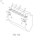
- FIG. 10 is an isometric view of a tool 150 for a press brake or similar machine apparatus, showing internal structure.
- tool 150 may contain a plurality of fixed magnet island assemblies 152 and a release lever 154.
- Tool 150 also includes a plurality of horizontal magnets 156 that collectively increase frictional holding of tool 150 within a corresponding tool holder.
- release lever 154 may be urged downward at distal end 155, thereby causing protrusion 157 to pivot about pin 158 and exert an outward force against an inner surface of the tool holder, effectively prying tool 150 away from the holder.
- Such prying may weaken the magnetic circuit generated by magnetic island assemblies 152 and the holder by urging the coupling end of the tool body 150 from the tool holder, creating an air gap in the magnetic flux path between the tool body 150 and the tool holder.
- Other decoupling members in addition or alternatively to lever 154, may be implemented in various examples. Each decoupling member can be configured to mechanically urge tool 150 away from a tool holder by creating an air gap therebetween, thereby allowing removal of tool 150 from the holder.
- the release or decoupling mechanism can include one or more pry bar or lever members 154 engaged with the tool or tool body 150. As shown in FIG. 10 , each pry bar or lever member 154 extends from a first end 155 to a second end or protrusion 157, with the second end 157 configured to selectively disengage the coupling end of the tool body 150 from the tool holder upon actuation of the first end.
- the first end 155 of the pry bar or lever member 154 may be accessible by a user, e.g., with the coupling end of the tool body 150 engaged in the tool holder, with the second end 157 of the pry bar or lever member 154 configured to protrude from the tool body 150 to selectively disengage the coupling end from the tool holder upon manipulation of the first end 155 by the user.
- a biasing element can be configured to bias the second end 157 of the pry bar or lever member 154 in a position disposed within the tool body 150, absent manipulation of the first end 155, or when the first end 155 is released.
- magnetic island assemblies 162 can be configured to induce a magnetic flux coupling with a tool holder.
- Each magnetic island assembly 162 may include one or more permanent magnets, ferromagnetic components, and/or non-ferromagnetic components configured to induce a magnetic flux coupling with a tool holder.
- the magnetic elements comprising each magnetic island assembly can be non-adjustable, such that the strength of the magnetic flux coupling depends only on the proximity of the upper portion of the tool 160 with a tool holder.
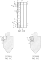
- FIG. 1 IB is a top transparent view of tool 160.
- each lever 166 can rotate about a rotational axis defined by a pin 174.
- the pins 174 extend into the body of tool 160, anchoring the levers 166 to the body of the tool.
- the coupling components e.g., magnetic island assemblies 162
- decoupling components e.g., decoupling ends 172
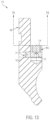
- FIG. 13 is a section view of tool 170 for a press brake or similar machine apparatus.
- tool 170 includes a magnetic coupling assembly MG with two isolated "island" magnetic assemblies configured for holding tool 170 within a tool holder TH (dashed lines), e.g., where tool holder TH utilizes a side-clamping mechanism.
- FIG. 14 is a section view of a press brake punch or tool 10 (or similar machine tool component 10, 60, 100, 130, 150, 160, 170), with a magnetic coupling mechanism MG disposed in tang end 13, opposite working end 12 of tool 10.
- Coupling mechanism MG is configured for selective engagement of tool 10 within tool holder TH, as described herein.
- Press Brake punches with a safety latch which can selectively hold the punch up into the holder until the holder clamping is activated, are useful for installing large punches or multiple punches.
- a safety latch which can selectively hold the punch up into the holder until the holder clamping is activated.
- There are various mechanisms for facilitating a releasable safety latch one of which is a straight-in pushbutton and latch-pawl.
- latching mechanisms not described in the prior art; this document describes such mechanisms.
- a magnetic safety latch mechanism is applied to a folding press or press brake punch, for example where a protrusion at the top of the punch fits into a receiving, downward-facing cavity in the punch holder.
- Such systems may have an actuating mechanism in the upper tool holder or punch holder, which clamps all of the punches simultaneously, for securely holding said punches in place while folding or forming the work-piece, which is typically sheet metal.
- Such tool holder systems have the advantage of simplicity, but make it awkward to deploy multiple punches without some mechanism to hold some punches in place, temporarily, while others are being installed.
- Conventional safety tang designs for their part, may require the punches to be installed in the correct order, and slid into the holder from one end.
- Other traditional safety latch mechanisms are known, such as laterally sliding or pivoting latches.
- magnets or magnetic assemblies could be installed horizontally in the punch tang to hold or help hold the punch up with the friction created by the magnetic force between the punch tang vertical sides and the vertical walls inside the punch holder. Also encompassed is the application of a permanent magnet or magnets, in the punch or punch holder, without a switching mechanism or release state, which would be especially practical for smaller punches wherein the magnetic forces holding the punch in the holder could be easily overcome by hand.
Landscapes
- Engineering & Computer Science (AREA)
- Mechanical Engineering (AREA)
- Bending Of Plates, Rods, And Pipes (AREA)
- Braking Arrangements (AREA)
Description
- Press brake tool systems are used for forming sheet metal and other workpieces, and commonly include an upper table and a lower table. The upper table can be equipped to move vertically with respect to the lower table. Various forming tools can be mounted to the tables, so that when the tables are brought together, the tools bend or impress a workpiece, such as a piece of sheet metal, placed therebetween.
- Typically, the upper table will couple with male forming tools, such as press brake and punch tools, and the bottom table will couple with female forming tools, such as dies. In order to perform a variety of forming operations, differently shaped press brake tools and dies are used. Thus, it is often necessary to exchange various forming tools within both the upper table and lower table.
- Because the forming tools mounted in the lower table are supported from below, they may be substituted with relative ease. The forming tools mounted to the upper table, however, are suspended from above, usually held in place by a clamping mechanism that clamps all of the forming tools simultaneously. Upon loosening, unlocking, or releasing the clamping mechanism, the forming tools mounted to the upper table may be removed by sliding the tools horizontally to an open end of the upper table, or in some instances, by removing the tools vertically. Horizontal exchange of the forming tools can be cumbersome due to the proximity of the forming tools with respect to one another in the upper table, often necessitating the removal of each tool mounted within the upper table when only one tool is being exchanged. Neighboring clamps may also interfere with horizontal removal of the tools.
- Vertical removal and insertion of the forming tools may not improve the exchange process due to the safety risks associated with handling the often heavy forming tools. In particular, loosening the clamping mechanism of the upper table may result in one or more tools falling and injuring a press brake operator.
- To prevent the forming tools from accidentally falling from the upper table of a press brake assembly, several safety mechanisms have been developed. One such mechanism may involve a safety tang that protrudes laterally from a surface of the forming tool. Such a safety tang may be shifted into a complementary groove defined by a tool holder in the upper table, thereby securing the tool to the holder until the tool is clamped. This mechanism is problematic, however, because of the manipulation required of the user to actuate the safety mechanism and secure the tool within the holder. Other preexisting safety mechanisms that involve forming tools equipped with a variety of latches, straps, or projections and complementary receiving spaces defined by tool holders are deficient for similar reasons. These designs typically employ a variety of movable external parts and often require a high degree of structural specificity between the design of each forming tool and corresponding tool holder.
- Thus, there exists a need for improved mechanisms used to secure forming tools to the upper table of a press brake assembly while the clamping mechanism of such an assembly is disengaged, such that heavy forming tools can be quickly exchanged without the risk of accidentally falling.
-
FR 2 791 590 A1EP 1 479 461 A1 andEP 1 321 200 A2 . - The invention is determined by the independent claims. Preferred embodiments are disclosed in the dependent claims.
- A tool includes a magnetic safety mechanism for operation in a press brake or similar machine apparatus. The mechanism includes a coupling assembly configured to provide a releasable magnetic coupling between the tool and a tool holder. A release is provided to selectively engage and disengage the magnetic coupling with the tool holder, alternately coupling and releasing the tool from the press assembly.
- A punch for a folding press or press brake, with a top protrusion or tang that fits into a cavity in said press brake's upper tool holder, with a safety mechanism for temporarily holding said punch in said press brake using a switchable or adjustable permanent magnet assembly to urge or retain the punch upward into a holder receiving cavity for placement or staging until said holder is activated, thus clamping said punch solidly in place for use, the punch thus having a locked position where said punch is safely restrained in said punch holder, or an unlocked setting, where said punch can be manually installed in or removed from said punch holder.
- The safety mechanism, where an assembly of permanent magnets and ferromagnetic parts are arranged to work cooperatively in a magnetic circuit, with some magnet(s) or part(s) made to be selectively moveable such that said magnetic circuit can be debilitated or weakened (as for punch installation or removal) or alternatively positioned so as to be optimized or enabled, to facilitate secure retention of punch in the holder until said holder is activated to clamp said punch solidly in the holder for folding operation.
- The safety mechanism, where the magnetic assembly includes one or more electromagnets which could be switchable to selectively aid or conflict with the magnetic circuit, to effect retention or release of said punch. The safety mechanism, where the magnetic assemblies consist of two or more parallel circuits of combinations of magnets and ferromagnetic parts such that one switchable or adjustable assembly is thus scalable for higher magnetic forces to compensation. The safety mechanism, provided with a mechanism for directly leveraging or prying the punch away from the holder.
- The safety mechanism, where one or more magnetic assemblies or permanent magnets are arranged along the length of a punch. The safety mechanism, where such magnetic assembly or assemblies employs a bi-stable or non-momentary locked and unlocked state. The safety mechanism, where the selectively moveable part or parts move slidably. The safety mechanism, where the selectively moveable part or parts move rotatably.
- A safety mechanism for holding a punch in a folding press or press brake using a permanent magnet assembly or permanent magnet or array of magnets to urge or retain the punch upward into a holder receiving cavity for placement or staging until said holder is activated to grip said punch solidly in place for use, such non-adjustable magnetic assembly being practical for smaller punches, where the forces encountered would be low enough that said punches could be manually installed or removed to or from said holder without further mechanical adjustment or rearrangement of the magnetic circuit.
- The safety mechanism, provided with a mechanism for directly leveraging or prying the punch away from the holder. The safety mechanism, where the magnets or magnetic assemblies are held in place with set-screws, glue, spring-pins, or such as are obvious variations of methods for securing said magnets or magnetic assemblies to the punch. The safety mechanism, where the magnet or magnets are installed in the punch shoulder or tang with additionally assembly features.
- A safety mechanism for holding a punch in a Folding Press or Press Brake using a permanent magnet assembly to urge the punch upward into a holder receiving cavity for placement or staging until said holder clamps said punch solidly in place for use, with non-adjustable magnets but with a mechanism for debilitating the magnetic circuit via an increasing gap or gaps in said magnetic circuit by leveraging or prying apart some part(s) within said magnetic circuit.
- The safety mechanism, with a selectable mechanism for dissipating magnetic flux away from the productive magnetic circuit by introducing a magnet or magnets or ferromagnetic part or parts to diverge some of the flux away from assisting in the punch-holding work of the magnetic circuit thus providing a selectably locked and unlocked state.
- A press brake tool comprising: a tool body having a working end configured for operation on a workpiece and a coupling end configured for selective engagement with a tool holder, the working end disposed generally opposite the coupling end; a magnetic assembly comprising one or more magnetic elements configured to generate a magnetic flux coupling adapted for the selective engagement of the coupling end of the tool body with the tool holder; and a coupling mechanism configured to manipulate at least one of the magnetic elements to modulate a strength of the magnetic flux coupling, where the coupling mechanism is adapted for selective disengagement of the coupling end of the tool body from the tool holder.
- The press brake tool, further comprising a tang formed on the coupling end of the tool body and adapted for the selective engagement with the tool holder, where the magnetic assembly is configured to generate the magnetic flux coupling between the tang and a magnetic component of the tool holder. The press brake tool, where the magnetic assembly comprises one or more permanent magnets disposed in the tang and configured to generate the magnetic flux coupling with the tool holder through one or both of a top surface and a side surface of the tang. The press brake tool, where the coupling mechanism comprise a magnetic armature configured to modulate the strength of the magnetic flux coupling by relative motion with respect to the one or more permanent magnets. The press brake tool, where the relative motion comprises transverse location of the armature with respect to the one or more permanent magnets. The press brake tool, further comprising a pushbutton type biasing member configured to retain the armature in alternate locked and unlocked positions, where the coupling end of the tool body is selectively engaged with and disengaged from the tool holder, respectively.
- The press brake tool, where the relative motion comprises rotation of the magnetic armature with respect to the one or more permanent magnets. The press brake tool, further comprising gear member configured for rotation of the armature between alternate locked and positions, where the coupling end of the tool body is selectively engaged with and disengaged from the tool holder, respectively. The press brake tool, further comprising a pushbutton coupled to the gear member via a rack and pinion assembly and adapted for rotation of the armature thereby.
- The press brake tool, further comprising a lever coupled to the armature for rotation thereof. The press brake tool, where the armature comprises transversely oriented magnetic elements configured for selective interaction with corresponding transversely oriented permanent magnets in the tang. The press brake tool, where the transversely permanent magnetics in the tang are adapted to generate the magnetic flux coupling through top surface and the side surface of the tang, respectively.
- A machine tool comprising: a first end configured for operation on a workpiece; a second end configured for engagement with a tool holder; a plurality of magnetic elements configured to generate magnetic flux couplings adapted for the engagement of the second end of the tool body with the tool holder; and a coupling mechanism configured to modulate the magnetic flux couplings, where the second end of the tool body is selectively disengaged from the tool holder.
- The machine tool, where the coupling mechanism comprises first and second magnetic armatures joined together by a transverse member. The machine tool, where first and second magnetic armatures have transversely oriented magnetic components.
The machine tool, where the first and second magnetic armatures are configured for modulating the magnetic flux coupling by selective interaction with different respective permanent magnet elements disposed in the second end of the machine tool. The machine tool, where the different permanent magnet elements are disposed to generate the magnetic flux coupling through a top surface and one or more side surfaces of the second end of the machine tool, respectively. - The machine tool, further comprising a magnetically permeable material disposed adjacent at least one of the magnetic elements and adapted to substantially magnetically isolate the at least one elements from others of the magnetic elements. The machine tool, where the magnetically permeable material is disposed adjacent a first set of the
magnetic elements disposed to generate a first component of the magnetic flux couplings through a top surface of the second end of the machine tool, substantially isolated from a second set of the magnetic elements disposed to generate a second component of the magnetic flux couplings through at least one side surface of the second end of the machine tool. The machine tool, further comprising one or more magnetic gaps disposed adjacent at least one of the plurality of magnetic elements, the magnetic gaps adapted to modulate at least one of the magnetic flux couplings by manipulation of the coupling mechanism with respect thereto. - Suitable press brake tool systems can include a tool body having a working end configured for operation on a workpiece and a coupling end configured for selective engagement with a tool holder, the working end spaced from the coupling end along the tool body; and one or more magnetic elements configured to induce a magnetic coupling between the tool body and the tool holder, where the coupling end of the tool body is magnetically engageable with the tool holder.
- The magnetic elements can include one or more magnets disposed in the tool body for generating magnetic flux to induce the magnetic coupling, one or more ferromagnetic elements disposed in the tool body for guiding magnetic flux to induce the magnetic coupling, or a combination thereof. The magnetic coupling can be sufficient to support a weight of the tool body upon engagement of the coupling end with the tool holder.
- The press brake tool systems include a mechanism configured for selective disengagement of the coupling end of the tool body from the tool holder. The mechanism comprises an actuator engaged with the tool body, the actuator configured to urge at least a portion of the coupling end from the tool holder to define an air gap therebetween.
- The mechanism can comprise a pry bar or lever member engaged with the tool body, the pry bar or lever member extending from a first end to a second end, the second end configured to selectively disengage the coupling end of the tool body from the tool holder upon actuation of the first end. The first end of the pry bar or lever member may be accessible by a user, e.g., with the coupling end of the tool body engaged in the tool holder, and where the second end of the pry bar or lever member is configured to protrude from the tool body to selectively disengage the coupling end of the tool body from the tool holder upon manipulation of the first end by the user. A biasing element can be configured to bias the second end of the pry bar or lever member in a position disposed within the tool body, absent manipulation of the first end.
- A load-bearing shoulder can be configured to bear a mechanical load between the tool holder and the tool body upon operation of the working end, where the second end of the pry bar or lever member is configured to protrude from the load-bearing shoulder to selectively disengage the coupling end from the tool holder. A pin or hinge element can be disposed between the first end of the pry bar or lever member and second end of the pry bar or lever member, e.g., where the pry bar or lever member is pivotably engaged with the tool body by the pin or hinge element. In some examples, the pry bar or lever member comprises a longitudinal portion extending from the first end to the pin or hinge element and a transverse portion extending transversely from the longitudinal portion, e.g., between the pin or hinge element and the second end.
- The mechanism can comprise a longitudinal shaft or pin member engaged with the tool body, the longitudinal shaft or pin member extending from a first end configured for actuation by a user to a second end configured to selectively disengage the coupling end of the tool body from the tool holder upon actuation of the first end. The longitudinal shaft or pin member may be disposed in sliding engagement with the tool body, e.g., with the second end configured to extend from the tool body to selectively disengage the coupling end from the tool holder upon actuation of the first end.
- The mechanism can comprise an armature having one or more magnets or ferromagnetic components configured to modulate a strength of the magnetic coupling by motion with respect to a flux path defined by disposition of the one or more magnetic elements in the tool body. The armature may be configured to rotate the one or more magnets or ferromagnetic components with respect to the flux path, or with respect to the poles of the magnetic elements defining the flux path. The armature may be configured for lateral motion of the one or more magnets or ferromagnetic components with respect to the flux path defined by magnetic assembly. A lever, knob or push button actuator can be engaged with the tool body, and mechanically coupled to the magnetic armature for manipulation of the one or more magnets or ferromagnetic components by the user to modulate the strength of the magnetic coupling. The mechanism may also comprise a plurality of armature members, each having one or more of the magnets or ferromagnetic components configured to modulate the strength of the magnetic coupling by rotational or lateral motion with respect to one or more flux paths defined by disposition of the one or more magnetic elements in the tool body.
- The magnetic elements may comprise one or more permanent magnets disposed in the tool body, the one or more permanent magnets configured to form the magnetic coupling between the tool body and the tool holder with the coupling end of the tool body engaged therein. One or more non-ferromagnetic elements may be disposed in the tool body and adapted for modulation of a flux path through the one or more magnetic elements, e.g., where the strength of the magnetic coupling is responsive to the modulation of the flux path.
- The one or more magnetic elements may comprise a plurality of magnetic sub-assemblies. Each magnetic sub-assembly may comprise one or more magnets or ferromagnetic elements configured to independently induce a magnetic coupling between the coupling end of the tool body and the tool holder.
- A tang can be defined by the coupling end of the tool body, and adapted for the selective engagement with the tool holder. One or more magnets or ferromagnetic elements may be disposed in the tang, and configured to induce the magnetic coupling by generating or guiding magnetic flux between the tang and the tool holder.
- A load-bearing shoulder can be defined on the tool body, and configured to bear a mechanical load between the tool holder and the tool body for operation of the working end of the tool body on a workpiece. One or more magnets or ferromagnetic elements may be disposed in the load-bearing shoulder, and configured to induce the magnetic coupling by generating or guiding magnetic flux between the load-bearing shoulder and the tool holder.
- Suitable methods of use and operation include disposing a tool body with respect to a tool holder, the tool body having a working end configured for operation on a workpiece, a coupling end spaced from the working end along the tool body, and one or more magnetic elements configured to induce a magnetic coupling; and engaging the working end of tool body with the tool holder, where the magnetic coupling is induced between the tool body and the tool holder. The magnetic elements may comprise one or more permanent magnets disposed in the tool body for generating magnetic flux to induce the magnetic coupling, one or more ferromagnetic elements disposed in the tool body for guiding magnetic flux to induce the magnetic coupling, or a combination
thereof. The magnetic flux coupling may be sufficient to support a weight of the tool body upon engagement of the coupling end with the tool holder. - An actuator mechanism may be engaged with the tool body, and operated to selectively disengage the coupling end of the tool body from the tool holder. Operating the actuator mechanism may comprise manipulating a knob, lever or pushbutton device coupled to the tool body, and mechanically engaged with a shaft or lever member configured to urge at least a portion of the coupling end of the tool body from the tool holder to define an air gap therebetween.
- Operating the actuator mechanism may comprise manipulating a pry bar or lever pivotally engaged with the tool body, the pry bar or lever configured to selectively disengage at least a portion of the coupling end of the tool body from the tool holder. Operating the actuator mechanism may also comprise accessing a first end of a lever or pry member engaged with the tool body, where the coupling end of the tool body is engaged in the tool holder; and manipulating the first end of the lever or pry member such that a second end of the lever or pry member protrudes from the tool body to selectively disengage the coupling end from the tool holder.
- Upon releasing the first end of the lever or pry member, the second end may be biased into a position disposed within the tool body. The second end of the lever or pry member may protrude from a load-bearing shoulder of the tool body upon manipulation of the first end, the load-bearing shoulder configured to bear a mechanical load between the tool holder and the tool body upon operation of the working end.
- Operating the actuator mechanism can comprise manipulating a longitudinal shaft in sliding engagement with the tool body. The longitudinal shaft can be configured for urging the coupling end of the tool body from the tool holder, e.g., when manipulated by a user.
- Operating the actuator mechanism can comprise manipulating one or more magnetic armatures with respect to a flux path defined by disposition of the one or more magnetic elements in the tool body. Manipulating the one or more magnetic armatures may comprise rotation or lateral motion of one or more magnets or ferromagnetic components with respect to the flux path, or with respect to the poles of the magnetic elements defining the flux path. A lever, knob or push button actuator can be
manipulated, e.g., by a user, to provide rotation or lateral motion of the one or more magnetic armatures with respect to the flux path. - Suitable methods include selectively engaging a tang on the coupling end of the tool body with the tool holder, where the magnetic coupling is induced by one or more of the magnetic elements disposed in the tang. Additional methods include selectively engaging a load-bearing shoulder defined on the tool body with the tool holder, where the magnetic coupling is induced by one or more of the magnetic elements disposed in the load-bearing shoulder.
- A press brake tool system includes a tool body having a working end configured for operation on a workpiece and a coupling end configured for selective engagement with a tool holder; a magnetic assembly configured to induce a magnetic coupling between the coupling end of the tool body and the tool holder; and a mechanism configured for selective disengagement of the magnetic coupling. The magnetic assembly may comprise one or more magnets disposed in the tool body for generating magnetic flux to induce the magnetic coupling, one or more ferromagnetic elements disposed in the tool body for guiding magnetic flux to induce the magnetic coupling, or a combination thereof. The magnetic coupling may be sufficient to support a weight of the tool body upon engagement of the coupling end with the tool holder.
- The mechanism can comprise a pry bar or lever actuator engaged with the tool body, the pry bar or lever actuator configured to urge at least a portion of the coupling end from the tool holder to define an air gap therebetween. The pry bar or lever actuator may comprise a first end accessible by a user and a second end configured to extend from the tool body to selectively disengage the coupling end from the tool holder upon manipulation of the first end by the user.
- The pry bar or lever actuator may comprise a longitudinal portion extending from a first end and a transverse portion extending transversely from the longitudinal portion to the second end. A pin or hinge may pivotably engage the pry bar or lever actuator with the tool body. A biasing element may bias the second end of the pry bar or lever actuator within the tool body, absent manipulation of the first end.
- A load-bearing shoulder can be configured to bear a mechanical load between the tool holder and the tool body upon operation of the working end. The second end of the pry bar or lever member may protrude from the load-bearing shoulder to selectively disengage the coupling end from the tool holder.
- The mechanism can comprise a longitudinal shaft or pin member disposed in sliding engagement with the tool body, and configured for actuation by a user to selectively disengage the coupling end of the tool body from the tool holder. The longitudinal shaft or pin member may comprise a first end mechanically engaged with an actuator and a second end configured to extend from the tool body to selectively disengage the coupling end from the tool holder upon manipulation of the actuator.
- The mechanism can comprise one or more magnetic armatures configured to modulate a strength of the magnetic coupling by motion with respect to a flux path defined by the magnetic assembly. The one or more magnetic armatures may each comprise one or more magnets or ferromagnetic components configured for rotation or lateral motion with respect to the flux path, or with respect to the magnetic elements defining the flux path. An actuator may be engaged with the tool body, and mechanically coupled to the one or more magnetic armatures for manipulation of the magnets or ferromagnetic components by a user to modulate the strength of the magnetic coupling.
- The magnetic assembly can comprise two or more magnetic subassemblies. The subassemblies may be configured to independently induce two or more respective magnetic couplings between the coupling end of the tool body and the tool holder.
- A tang may be defined by the coupling end of the tool body and adapted for the selective engagement with the tool holder, e.g., where the magnetic assembly comprises one or more magnets or ferromagnetic elements disposed in the tang to induce the magnetic coupling between the tang and the tool holder. A load-bearing shoulder may be defined on the tool body to bear a mechanical load between the tool holder and the tool body upon operation of the working end, e.g., where the magnetic assembly comprises one or more magnets or ferromagnetic elements disposed in the load-bearing shoulder to induce the magnetic coupling between the load-bearing shoulder and the tool holder.
-
-
FIG. 1 A is an isometric view of a tool for a press brake apparatus. - FIG. IB is a front view of the tool.
-
FIG. 1C is a top view of the tool. - FIG. ID is an alternate top view of the tool.
- FIG. IE is a section view of the tool, taken along line A-A of
FIG. 1C . - FIG. IF is a top view of a magnetic coupling assembly for the tool, taken at detail K in FIG. ID.
-
FIG. 1G is a section view of the tool, taken at detail H of FIG. IE and along line A-A ofFIG. 1C . -
FIG. 2 is an exploded view of the magnetic coupling assembly and an armature. -
FIG. 3A is a section view of the tool, taken along line B-B of FIG. ID. -
FIG. 3B is an alternate section view of the tool with the coupling assembly in a disengaged configuration, taken along line B-B of FIG. ID. -
FIG. 4 is an isometric view of a tool for a press brake apparatus, showing the internal configuration with an alternate magnetic coupling configuration. -
FIG. 5 is an isometric section view of a tool for a press brake apparatus, in an embodiment having an alternate magnetic coupling assembly. -
FIG. 6 is an alternate isometric section view of the tool, transverse toFIG. 5 . -
FIG. 7A is an isometric view of the tool ofFIG. 5 , including a magnetic coupling assembly detail. -
FIG. 7B is a front view of the tool. -
FIG. 7C is a top view of the tool. -
FIG. 7D is an alternate top view of the tool. -
FIG. 7E is a section view of the tool at detail H, taken along line A-A ofFIG. 7C , showing magnetic flux paths. -
FIG. 7F is an alternate section view of the tool. -
FIG. 7G is a further section view of the tool, taken along line B-B ofFIG. 7D . -
FIG. 8A is an isometric view of the tool, with an external handle mechanism. -
FIG. 8B is a top view of the tool showing the handle mechanism. -
FIG. 8C is a section view of the handle mechanism, taken along line C-C ofFIG. 8B . -
FIG. 8D is a section view of the tool in an engaged position, taken along line B-B ofFIG. 8B . -
FIG. 8E is an alternate section view of the tool in a released position. -
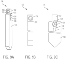
FIG. 9A is an isometric view of a tool for a press brake apparatus, in a narrow profile configuration. -
FIG. 9B is a front view of the tool inFIG. 9A . -
FIG. 9C is a side view of the tool. -
FIG. 9D is a top view of the tool. -
FIG. 9E is a section view of the tool, taken along line A-A ofFIG. 9D . -
FIG. 9F is an alternate section view of the tool at detail H ofFIG. 9E . -
FIG. 10 is an isometric view of a tool for a press brake or similar machine apparatus, showing an alternate internal magnetic coupling structure and a decoupling member. -
FIG. 11A is an isometric view of a tool for a press brake or similar machine apparatus, showing two decoupling members. -
FIG. 1 IB is a top transparent view of the tool ofFIG. 11 A . -
FIG. 11C is a section view of the tool, taken along line A-A ofFIG. 1 IB. -
FIG. 1 ID is another section view of the tool, taken along line B-B ofFIG. 1 IB. -
FIG. 12A is a top transparent view of a tool for a press brake or similar machine apparatus, showing alternate decoupling mechanisms. -
FIG. 12B is a front transparent view of the tool ofFIG. 12A , showing the internal components of the decoupling mechanisms. -
FIG. 12C is a section view of the tool, taken along line A-A ofFIG. 12A . -
FIG. 12D is another section view of the tool, taken along line B-B ofFIG. 12A . -
FIG. 13 is a section view of a tool for a press brake or similar machine apparatus. -
FIG. 14 is a section view of a press brake punch or tool coupled with a tool holder. -
FIG. 1A is an isometric view of atool component 10 for a press brake machine or similar press-type machine apparatus. While generally described as a press brake tool herein,component 10 may alternately be configured as a press brake punch, punch tool, or similar machine tool component. - As shown in
FIG. 1A ,tool 10 includes a tool end or workingend 12 opposite a coupling end ortang 13. Depending on the particular configuration oftool 10, workingend 12 may be generally positioned beneath coupling end ortang 13, such that workingend 12 is the bottom end and coupling end ortang 13 is the top end.Tang 13 may be mounted within a corresponding tool holder as part of a press brake assembly. In operation, such a press brake assembly may punch, impress, crimp, fold, crease, or otherwise shape various workpieces inserted beneath workingend 12 and optionally one or more forming dies. In some examples, a workpiece may include a sheet metal component or other material to be tooled. - In these examples,
tool 10 may include two load-bearing shoulder portions tang 13.Shoulder portions tool 10 within the holder, in order to bear or transfer a load between the tool holder and the tool body upon operation of the working end on a sheet metal component or other workpiece. -
Tool 10 also includes a plurality ofmagnetic assemblies 18 vertically disposed withintang 13 andtool body 21. Eachmagnetic assembly 18 may include one or more magnetic elements, which may include one or more permanent magnets, ferromagnetic components, or combinations thereof. As illustrated, eachmagnetic assembly 18 may be partially exposed through atop surface 20 oftang 13. In this particular example,tool 10 includes threemagnetic assemblies 18. In other examples, the number ofmagnetic assemblies 18 in a giventool 10 may vary, ranging from 1 to about 50magnetic assemblies 18. Eachmagnetic assembly 18 may be removable, adjustable, or fixed withintool 10. - The
body 21 oftool 10 may include front and back surfaces 26 and 28. In examples, surfaces 26, 28 may be variously shaped and sized depending on the desired function oftool 10.Tool 10 may further define alateral cavity 22, of which only the opening is visible inFIG. 1A .Lateral cavity 22 may be configured to slidably receive anarmature 24, which is shown fully inserted within the lateral cavity inFIG. 1A . In the embodiment shown,armature 24 provides a coupling mechanism configured to modulate the strength of a magnetic flux coupling induced betweentool 10 and the holder. In some examples,armature 24 can be adapted for selective disengagement of the coupling end ortang 13 oftool 10 from the holder.Armature 24 contains one or more dynamic or moving elements, which can include one or more magnetic elements, e.g., permanent magnets and/or ferromagnetic components. - Once inserted into the receiving space defined by a tool holder,
tool 10 may be held in place at least temporarily by magnetic forces prior to clampingtool 10 with the holder. In particular, the magnetic elements ofmagnetic assemblies 18 andarmature 24 may align such as to guide a magnetic flux in a circuit further involving a ferromagnetic material, e.g., medium alloy steel, comprising the tool holder. The magnetic flux can urgetool 10 upwardly into the tool holder so as to minimize non-ferromagnetic gaps, e.g., air gaps, between the two components, thus holdingtool 10 up against the load- impinging shoulder surfaces of the holder. In some examples, the magnetic flux coupling induced betweentool 10 and its tool holder can support the weight of the tool without additional clamping support. By holdingtool 10 in place prior to clamping a tool holder around the upper portion oftool 10, a user's hands may be free to install additional tools until the holder is activated to lock all tools in place for operation on a workpiece. In some embodiments, the strength of the magnetic flux coupling can securetool 10 even during operation on a workpiece without additional clamping support. - FIG. IB is a front view of
tool 10. As illustrated in FIG. IB,magnetic assemblies 18 may protrude a distance abovetop surface 20. The distance by whichmagnetic assemblies 18 protrude abovetop surface 20 may vary. - Press brake tool system or
apparatus 10 includes atool body 21 with a working end configured for operation on a workpiece, and a coupling end configured for selective engagement with a tool holder. The working end is spaced from the coupling end along the tool body, e.g. at opposite top and bottom ends. One or moremagnetic assemblies 18 can be configured to induce a magnetic coupling between thetool body 21 and the tool holder, where the coupling end of the tool body is magnetically engageable with the tool holder. - The
magnetic assemblies 18 can include one or more magnets disposed in thetool body 21 for generating magnetic flux to induce the magnetic coupling, one or more ferromagnetic components disposed in thetool body 21 for guiding magnetic flux to induce the magnetic coupling, or a combination thereof. Typically, the magnetic coupling is sufficient to support the weight of thetool body 21 upon engagement of the coupling end with the tool holder. -
FIG. 1 C is a top view oftool 10, showing each of the threemagnetic assemblies 18 included in this particular example. In other examples, the number, spacing, and arrangement ofmagnetic assemblies 18 withintool 10 may vary. As shown inFIG. 1C , eachmagnetic assembly 18 may include twoassembly slugs 30 laterally flanking each side of anend guide 32. Assembly slugs 30 andend guide 32, along with other components of eachmagnetic assembly 18, may be contained within ahousing 19, which can be fixed withintool 10. In some examples, such components may be cast or mold intohousing 19 to form eachmagnetic assembly 18.Housing 19 may be a structural insert that defines the external shape of eachmagnetic assembly 18 and its internal
compartments. Such an insert may be made from various materials including but not limited to one or more plastics or polymer compositions. - In embodiments, the number of assembly slugs 30 and end guides 32 may vary. Each
assembly slug 30 may be made from various materials including but not limited to a magnetically permeable material, e.g., one or more metals such as steel. In some examples, such magnetically permeable material may be highly permeable. End guides 32 may also be made from various materials including but not limited to iron or steel, e.g., electrical steel.FIG. 1C also shows line A-A, which denotes a cross-sectional plane used for illustration purposes. - FIG. ID is an alternate top view of
tool 10, showing threemagnetic assemblies 18 exposed at one end throughtop surface 20. FIG. ID also shows line B-B, which denotes a cross-sectional plane, and detail K, used for illustration purposes. - The
magnetic assemblies 18 can include one or more permanent magnets disposed in thetool body 21, and configured to form a magnetic coupling between the tool body and the tool holder with the coupling end of thetool body 21 is engaged. One or more non-ferromagnetic components can also be disposed in the tool body, and adapted for modulation of a flux path through the one or more magnetic elements (e.g., where the strength of the magnetic coupling is responsive to the modulation of the flux path). Similarly, a plurality ofmagnetic sub-assemblies 18 may each include one or more magnets, ferromagnetic elements or non-ferromagnetic components configured to independently induce a magnetic coupling between the coupling end of thetool body 21 and the tool holder. - A
tang 13 can be defined by the coupling end of the tool body, and adapted for the selective engagement with the tool holder. One or more magnets or ferromagnetic components can be disposed in thetang 13, and configured to induce the magnetic coupling by generating or guiding magnetic flux between thetang 13 and the tool holder. - One or more load-
bearing shoulders tool body 21 on a workpiece. One or more magnets or ferromagnetic components can also be disposed in the load-bearing shoulder bearing shoulder - FIG. IE is a section view of
tool 10, taken along line A-A ofFIG. 1C . This section view illustrates the inner portion of amagnetic assembly 18 andarmature 24 inserted therethrough, each component positioned withintool 10. As shown in this particular view,magnetic assembly 18 can include anassembly magnet 34, multiple end guides 32 and a return flux guide orloop component 38, each contained withinhousing 19.Armature 24 can include anarmature magnet 36. FIG. IE also shows an outline of the bottom portion of an exemplary tool holder TH (dashed lines) with whichtool 10 is magnetically coupled and clamped into a press brake machine or similar machine apparatus. In various embodiments, tool holder TH can be a preexisting, conventional tool holder lacking discrete magnetic components and made of steel, for example. - In some examples,
assembly magnet 34 may comprise a permanent magnet made from one or more magnetic materials, e.g., neodymium iron boron ("NdFeB").Assembly magnet 34 may be a bar magnet. - In the particular configuration of FIG. IE,
armature magnet 36 is included withinarmature 24 and positioned beneathassembly magnet 34 whenarmature 24 is inserted withinlateral cavity 22. Likeassembly magnet 34,armature magnet 36 may also be a permanent magnet made of NdFeB. In some embodiments,armature magnet 36 may be made of other magnetic materials.Armature magnet 36 may be magnetized diametrically and oriented such that the north pole ofarmature magnet 36 is in closest proximity to the south pole ofassembly magnet 34. - In the example of FIG. IE, end guides 32 are positioned above
assembly magnet 34, and betweenassembly magnet 34 andarmature magnet 36. In some examples, end guides 32 may be made from various materials including but not limited to one or more metals, e.g., iron or electrical steel. -
Return flux guide 38 is positioned beneatharmature magnet 36 in this example, and is also contained withinhousing 19 as a sub-component ofmagnetic assembly 18.Return flux guide 38 may comprise a magnetically permeable material. In some examples, such material may be highly permeable. - In the example depicted in FIG. IE,
magnetic assembly 18 extends downward throughtang 13 and into avertical cavity 39 defined bytool body 21 to a distance below the horizontal plane ofshoulders magnetic assembly 18 extends withintool 10 may vary and may depend on the shape, weight,
and/or size oftool 10, the number ofmagnetic assemblies 18 included within a giventool 10, and/or the configuration of the tool holder into whichtool 10 is inserted. As further shown, anair gap 33 may be defined beneath the bottom-most surface offlux guide 38 inmagnetic assembly 18, at the bottom ofvertical cavity 39. In these examples,gap 33 may contribute to a desired magnetic flux direction induced bytool 10 and the holder by providing a non-ferromagnetic component positioned to modulate the magnetic flux coupling, e.g., by guiding the magnetic flux or by modifying or disrupting the flux path. - FIG. IF is a top view of a vertical
magnetic assembly 18, taken at detail K in FIG. ID. Detail K illustrates a magnified view of the top of eachmagnetic assembly 18. As in FIG. IF, each magnetic assembly may include two D-shaped assembly slugs 30 and anend guide 32 exposed attop surface 20.Housing 19, also visible attop surface 20, may laterally partition assembly slugs 30 andend guide 32. -
FIG. 1G is a section view of detail H taken along section A-A. As shown inFIG. 1G ,assembly magnet 34 may define an approximately rectangular cross-sectional shape, andarmature magnet 36 may define an approximately circular cross-sectional shape. In other examples, the shape of each magnet may vary. The cross-sectional width of each wall ofhousing 19 may also vary. In this particular embodiment, the cross-sectional width of each exterior wall ofhousing 19 may be the greatest neartop surface 20. -
FIG. 2 is an exploded view of amagnetic assembly 18 andarmature 24. In this example,magnetic assembly 18 defines an aperture 40 configured to slidably receivearmature 24 such thatmagnetic assembly 18 andarmature 24 intersect. As shown, aperture 40 may define a lateral through-hole. Aperture 40 may align withlateral cavity 22 oftool 10, such thatarmature 24 is configured to slide seamlessly through aperture 40 andtool 10. - As further shown in
FIG. 2 , the sub-assemblies ofmagnetic assembly 18 andarmature 24 may include numerous distinct components. In particular,assembly magnet 34, returnflux guide 38, eachend guide 32, and eachassembly slug 30 may be separate sub-components of eachmagnetic assembly 18, arranged to generate a magnetic circuit upon assembly witharmature 24 and insertion within a tool holder.Housing 19 may define one or more internal compartments for containing each of the internal components ofmagnetic assembly 18. In this embodiment,housing 19 is cylindrical, but the shape ofhousing 19 may vary in other examples. - Each
armature 24 can include a plurality of dynamic elements, such asarmature magnets 36, which can be permanent magnets in various embodiments. In this particular example,armature 24 includes threearmature magnets 36 each flanked by a pair of D-shaped armature slugs 31. The armature slugs 31 can comprise ferromagnetic wedges. When inserted withintool 10,armature magnets 36 andslugs 31 can align with the magnetic elements included within eachmagnetic assembly 18. In embodiments,armature 24 can include one or more permanent magnets, electromagnets, ferromagnetic components, and/or non-ferromagnetic components collectively arranged to strengthen or support a magnetic circuit betweentool 10 and the holder.Armature 24 may further include anend portion 42 that may be manually engaged by a user oftool 10 to insert and removearmature 24 therefrom. In some examples,end portion 42 may comprise a handle, knob, protrusion, or other feature graspable by a user. -
FIG. 3A is a section view oftool 10, taken along line B-B of FIG. ID. In this example,tool 10 may define an internallateral cavity 22 configured to slidably receivearmature 24. A bias member 46, e.g., a spring, may be secured at a stop end 48 ofcavity 22, protruding laterally withincavity 22 such thatarmature 24 contacts bias member 46 upon insertion intocavity 22.Cavity 22 may define a receiving end 50 positioned opposite stop end 48. Receiving end 50 may define a greater cross-sectional height and/or width to accommodatearmature end portion 42. - As further shown in
FIG. 3A , assembly slugs 30 may be laterally partitioned from eachend guide 32,assembly magnet 34,armature magnet 36, and flux guide 38 byhousing 19. Anassembly slug 30 andarmature slug 31, in combination, may extend vertically fromtop surface 20 to the top plane offlux guide 38. -
Armature 24 may be inserted to various depths withincavity 22. The depth at which armature 24 is inserted may determine whethertool 10 is in an engaged, locked position or a disengaged, unlocked position. In some examples, movement ofarmature 24 can switch the strength of the magnetic flux coupling between two bi-stable states: an engaged state in which the magnetic flux coupling betweentool 10 and the holder is established, and a disengaged state in which the magnetic flux coupling betweentool 10 and the holder is diminished or absent.FIG. 3A depicts the locked position, in which armature 24 contacts, but may not compress, bias member 46. Accordingly, the locked position may represent a relaxed position. In this configuration, armature 24 functions as a button that can be manually pressed to various depths withincavity 22 by exerting various amounts of lateral force againstarmature end portion 42. As shown in the locked position ofFIG. 3A ,armature end portion 42 is inserted withincavity 22 such that its end surface is flush with the end surface oftool 10. - In the locked position,
assembly magnet 34 included in eachmagnetic assembly 18 may be magnetically oriented the same as eacharmature magnet 36. In these examples, eachassembly magnet 34 is oriented such that its north pole is positioned above its south pole, and eacharmature magnet 36 is similarly oriented such that its north pole is oriented above its south pole. In this orientation,assembly magnet 34armature magnet 36, surrounded by the additional ferromagnetic components oftool 10 and its corresponding tool holder, may form a magnetic circuit that generates a magnetic flux 52 that passes vertically through eachend guide 32, loops through a ferromagnetic material comprising the tool holder whentool 10 is in the locked position within a receiving space defined by the holder. It may be desirable that magnetic circuit involves the shoulders of the tool holder: first to holdtool 10 firmly against such shoulders so thattool 10 is in an ideal position for clamping by a press brake or similar machine apparatus, and secondly because the gap between thetang 13 and the inside of the holder is designed as clearance and may therefore not be a precise or sufficiently small gap that it could be depended upon to form a reliable part of the magnetic circuit. - After passing through the tool holder, magnetic flux 52 may be guided back down into each
assembly slug 30, which, together with eacharmature slug 31, may function as a ferromagnetic wedge that propagates magnetic flux 52 downward through eachmagnetic assembly 18. At the bottom of eacharmature slug 31, magnetic flux 52 may loop horizontally, viareturn flux guide 38, and back upward through the south pole ofarmature magnet 36. - As further shown in
FIG. 3A ,air gaps 33 and 56 may be present at the bottom of eachvertical aperture 39 and receiving end 50, respectively.Gaps 33 and 56 may function as non-ferromagnetic gaps to prevent magnetic flux 52 from dissipating withinbody 21 oftool 10 beneathvertical aperture 39 and receiving end 50, thereby maintaining an upward flux direction. -
FIG. 3A also shows that the body ofarmature 24 may be made from aluminum. In other examples, the body ofarmature 24 may be made from various different and/or additional materials. In this example, eachflux guide 38 is made from a high permeability soft magnetic material. Other magnetic materials may also be suitable, depending upon flux density and other application-specific considerations. -
FIG. 3B is a section view oftool 10 in an unlocked configuration, taken along line B-B of FIG. ID. In the unlocked configuration,armature 24 may be urged a greater distance withinlateral cavity 22, thereby compressing bias member 46. The magnetic poles of eachassembly magnet 34 andarmature magnet 36 are misaligned, creating a conflicting, and therefore much weaker, magnetic circuit. The reduced flux 52 generated within such a circuit may reduce the holding force betweentool 10 and a corresponding tool holder, allowing manual insertion and removal oftool 10 with respect to the holder. In some examples, gravity alone may causetool 10, in the unlocked configuration, to fall from a corresponding tool holder. - The release mechanism can include any
suitable armature 24 having one or more magnets orferromagnetic components 36 configured to modulate a strength of the magnetic coupling by motion with respect to the flux path defined by disposition of the one or moremagnetic elements 34 in the tool body. Thearmature 24 can rotate the magnets orferromagnetic components 36 with respect to the flux path, or with respect to the poles of themagnetic elements 34 defining the flux path. Thearmature 24 can also be configured for lateral motion of the one or more magnets orferromagnetic components 36 with respect to themagnetic elements 24 and the flux path defined by themagnetic elements 34. A lever, knob or push button actuator can be engaged with thetool body 21, and mechanically coupled to themagnetic armature 24 for manipulation of the magnets orferromagnetic elements 36 by the user to modulate the strength of the magnetic coupling. The release mechanism may also comprise a plurality ofarmature members 24, each having one or more of the magnets orferromagnetic elements 36 configured to modulate the strength of the magnetic coupling by rotational or lateral motion with respect to one or more flux paths defined by disposition of the one or moremagnetic elements 34 of themagnetic assembly 18 within thetool body 21. -
FIG. 4 is an isometric view of an upper portion oftool 60 for a press brake or similar machine apparatus. As shown inFIG. 4 ,tool 60 may include a t-shaped magnetic circuit assembly with a sliding armature. The example ofFIG. 4 includes two top magnets 62 included within tang 71. A portion of each top magnet 62 may be exposed at the top surface 65 oftool 60.Tool 60 further includes side magnets 64 within tang 71 , each exposed at reference face 66. - Top and side magnets 62, 64 can be fixed within
tool 60. Each top magnet 62 may be vertically oriented such that its north pole is positioned above its south pole. In some examples, top magnet 62 may be arranged in the opposite polar orientation. Each side magnet 64 may be oriented such that its north pole is positioned on the left side and its south pole on the right side, or vice versa. With respect to the magnetic orientation of top magnets 62, side magnets 64 may thus be oriented in an opposing orientation. Regardless of the specific polar orientation, each side magnet 64 may include a magnetic pole facing the exterior oftool 60, and a magnetic pole facing the interior oftool 60. In any or all of the various examples included herein, the polar orientation of each magnet may be reversed, provided that the polarity of each magnet relative to the other magnets comprising the magnetic circuit remains the same. -
Armature 68 can provide a coupling mechanism configured to modulate the strength of the magnetic flux coupling betweentool 60 and the holder.Armature 68 is shown inserted within parallel lateral cavities defined bytool 60. In particular,tool 60 includes two lateral cavities: an upper cavity 70 positioned above a lower cavity 72. First orupper arm 74 ofarmature 68 may be slidably inserted into upper cavity 70, and second arm 76 may be slidably inserted into lower cavity 72.First arm 74 and second arm 76 may be connected at one end by a vertical ortransverse armature member 77. While the particular arrangement of upper cavity 70 and/or lower cavity 72 may vary,FIG. 4 illustrates that upper cavity 70 may be defined within tang 71, and lower cavity 72 may be defined below the plane ofshoulders 73, 75 that demarcate the lower boundary of tang 71. The exterior surface oftransverse member 77 may remain accessible upon insertion ofarmature 68 withintool 60 such thattransverse member 77 may be manually engaged by a user to insertarmature 68 withintool 60, and to adjust the lateral depth at which armature 68 extends intotool 60.Upper arm 74 and lower arm 76 ofarmature 68 can each include one or more dynamic or moving elements, which may include permanent magnets and/or ferromagnetic components. - As further shown in
FIG. 4 , abias member 78 may be secured to a stop end 80 defined by lower cavity 72. In this example,bias member 78 comprises a spring. In a locked or engaged configuration,bias member 78 may not be compressed, or may be only slightly compressed, by second arm 76 ofarmature 68.Tool 60 also includes two vertical cavities 81. In some examples, the number of vertical cavities may vary and may depend on the number of top magnets 62 needed to form a magnetic circuit witharmature 68 strong enough to at least temporarilysecure tool 60 within a tool holder. - Adjusting the position of
armature 68 can modulate the strength of the magnetic flux coupling betweentool 60 and the holder. For example, insertingarmature 68 to a greater depth withintool 60 by compressingbias member 78 can cause misalignment between the magnetic poles of the dynamic elements of the armature and the magnetic poles of the top magnets 62 and side magnets 64, thus disrupting the magnetic flux coupling betweentool 60 and the holder and allowing for release of the tool. By contrast, when the magnetic elements included inarmature 68 are magnetically aligned with top and side magnets 62, 64 fixed withintool 60, a magnetic circuit can be established, thereby inducing a magnetic flux guided from tang 71 through reference face 66 into a ferromagnetic shoulder portion of a tool holder coupled withtool 60. Slidingarmature 68 in this manner can gradually modulate the strength of the magnetic flux coupling betweentool 60 and the holder. -
FIG. 5 is an isometric section view of atool 100 for a press brake or similar machine apparatus, taken along the length or longitudinal direction oftool 100.Tool 100 may include a cross-shaped circuit assembly with a rotating armature. In the particular configuration ofFIG. 5 ,tool 100 includes two verticalmagnetic assemblies 101 , eachassembly 101 including afirst magnet 102 and asecond magnet 103.First magnet 102 may be exposed at top surface 115, positioned above alateral cavity 105 defined bytool 100.Second magnet 103 may be positioned belowlateral cavity 105. As further shown in the figure,focal wedges 104 may be sandwiched between eachfirst magnet 102 andlateral cavity 105, as well as between eachsecond magnet 103 andlateral cavity 105. -
Tool 100 also includes a rotating armature 1 16, which provides a coupling mechanism configured to modulate the strength of the magnetic flux coupling betweentool 100 and the holder. By rotating, armature 1 16 may adjust the polar orientation of one or more dynamic elements, e.g.,permanent disc magnets 106 and ferromagnetic collar 1 13, contained in the armature and inserted withinlateral cavity 105. Rotating the dynamic elements ofrotating armature 116 may gradually modulate the strength of the magnetic flux coupling along a spectrum from high strength to low or zero strength. This particular example includes twodisc magnets 106 and oneferromagnetic collar 113, but the number of dynamic magnetic components can vary depending upon tool size and application. - As further shown in
FIG. 5 ,tool 100 may also include anupper gear member 108, which includes an elongate body 109 that extends through at least a portion oflateral cavity 105.Upper gear member 108 may rotatably engage anadjacent pinion 110 via a plurality of complementary grooves, or mechanical teeth, protruding outward from the perimeter of bothgear member 108 andpinion 110. Together,pinion 110 andgear member 108 comprisegear assembly 112. An idler gear 111 may be also positioned at the radial center ofpinion 110.Pinion 110 may rotatably engagerack 114 via a plurality of complementary grooves or mechanical teeth also protruding fromrack 114. - In operation, lateral movement of
rack 114, e.g., sliding, may drive rotation ofarmature 116. Specifically, lateral movement ofrack 114 may causepinion 110 to rotate, thereby causing rotation ofupper gear member 108. Because body 109 ofupper gear member 108 is secured within the radial center of eachdisc magnet 106, rotation of body 109 also drives rotation of eachdisc magnet 106, thereby adjusting the polarity of eachdisc magnet 106 with respect tofirst magnets 102 andsecond magnets 103. -
FIG. 6 is an isometric section view taken along the width oftool 100, transverse to the view ofFIG. 5 . As further detailed inFIG. 6 ,tool 100 may include one ormore side magnets 118, 119. A lateralfocal wedge 120 may be sandwiched between eachside magnet 118, 119 anddisc magnet 106. In this particular example,disc magnet 106 is magnetized axially such that it includes four magnetic poles. -
FIG. 7A is an isometric view oftool 100. As shown inFIG. 7 A ,tool 100 may include anexterior button 122. In this example,button 122 protrudes outward from front surface 123, where it may be manually engaged by a user, for example. To rotatearmature 116, thereby either releasing or lockingtool 100 within a corresponding tool holder,button 122 may be pushed. Pushingbutton 122 causes rack 114 to move laterally, thus causingpinion 110 andupper gear member 108 to rotate.Disc magnets 106 secured to gearmember 106 may then be rotated, causing a shift in magnetic alignment withintool 100. -
FIG. 7B is a front view oftool 100. As shown inFIG. 7B , eachfirst magnet 102 may protrude above the plane defined by top surface 115.Button 122 is positioned beneathtang 125, withinbody 107 oftool 100. -
FIG. 7C is a top view oftool 100.FIG. 7D is an alternate top view oftool 100, showing section B-B. - As shown in
FIGS. 7B and7C , a first set ofmagnets 102 may be exposed at top surface 115. This particular embodiment includes two verticalmagnetic assemblies 101. In other examples, the number, size, and/or arrangement ofmagnetic assemblies 101 may vary.Button 122 is shown protruding laterally outward fromtool 100.FIG. 7C also shows line A-A, which denotes a cross-sectional plane used for illustration purposes. -
FIG. 7E is a section view of detail H, taken along section A-A ofFIG. 7C . Withbutton 122 in a relaxed position,tool assembly 100 is in a locked or engaged configuration with respect to the tool holder. In the locked position,tool assembly 100 may form two magnetic circuits comprised of separate pathways of magnetic flux: flux pathway fi and flux pathway f2. As shown inFIG. 7E , flux pathway fi is guided in a counterclockwise direction throughdisc magnet 106 tofirst magnet 102, through top surface 115 oftang 125 into a ferromagnetic portion of a tool holder TH, and back through one ofside magnets 118. The altemating magnetic poles ofdisc magnet 106,top magnet 102, andside magnet 118 in this configuration may generate the closed magnetic circuit defined by flux pathway f2. - Similarly, flux pathway f2 is generated by the alternating magnetic poles of
disc magnet 106,side magnets 118, andsecond magnet 103. As shown in the figure, flux pathway f2 may be guided in a clockwise direction, passing fromdisc magnet 106 tosecond magnet 103, through a ferromagnetic shoulder portion of a tool holder TH, and back throughside magnet 118. - In combination, flux pathways fi and f2 may generate a strong upward force to at least temporarily
secure tool 100 within a corresponding tool holder. By generating two circuits that work in cooperation,tool 100 may drive a magnetic flux through a larger portion of tool holder TH relative to other tool and punch designs. - As further shown in
FIG. 7E ,first magnet 102 may be an NdFeB disc, which may also be large, whileside magnets 118 may be smaller, axially magnetized NdFeB discs.Disc magnet 106 may also be an NdFeB magnet.Disc magnet 106, however, may be
magnetized radially.Focal wedges 104 and lateralfocal wedges 120 may each be made of iron-nickel compositions in one example. -
FIG. 7F is a section view oftool 100, taken along section A-A ofFIG. 7C .FIG. 7F showstool 100 in a release position caused by pressingbutton 122. As shown inFIG. 7F , pressingbutton 122 causesdisc magnet 106 to rotate. In some examples,disc magnet 106 will rotate up to about 90°.Armature 116 may resist the rotation ofdisc magnet 106 beyond 90° such that no internal bias member, e.g., spring, may be necessary. In some examples, a bias member may be included to prevent over-rotation ofarmature 116.
Rotation ofdisc magnet 106 causes the magnetic poles betweendisc magnet 106,first magnet 102,second magnet 103, and eachside magnet 118 to misalign, thereby nearly cancelling magnetic circuits x and y. Without a magnetic flux throughtool 100 and a tool holder, theforce urging tool 100 upward into a tool holder may be diminished, allowing removal oftool 100 from the tool holder. - As further shown in
FIG. 7F ,non-ferromagnetic sleeves 124 may housemagnetic assemblies 101 andside magnets 118 withintool 100. -
FIG. 7G is a section view oftool 100 taken along line B-B ofFIG. 7D . In this example, body 109 may extend the entire length oflateral cavity 105. -
FIG. 8A is an isometric view oftool 60 for a press brake or similar machine apparatus. As shown inFIG. 8A ,tool 60 includes anexternal handle mechanism 85. In this particular embodiment, handlemechanism 85 includes a slidable handle component that protrudes from front surface 59 oftool 60.Handle mechanism 85 may be shaped to be graspable by a user. By movinghandle mechanism 85 laterally,armature 68 may be moved laterally withintool 60. Thus, handlemechanism 85 may be engaged toalternate tool 60 from a locked to an unlocked configuration. -
FIG. 8B is a top view oftool 60. As shown inFIG. 8B , handlemechanism 85 protrudes laterally outward fromtool 60 for user access. -
FIG. 8C is a section view ofhandle mechanism 85, taken along line C-C ofFIG. 8B .Handle mechanism 85 may be coupled, attached, or otherwise secured to armature 68 viatransverse member 77. In some examples, handlemechanism 85 may be directly or indirectly coupled toarmature 68. For instance, handlemechanism 85 may be inserted into an aperture or cavity defined bytransverse member 77. As depicted inFIG. 12C , handlemechanism 85 may be secured to the outer surface oftransverse member 77. In other embodiments, handlemechanism 85 may be integrally formed withtransverse member 77. -
FIG. 8D is a section view oftool 60, taken along line B-B ofFIG. 8B .FIG. 8D illustratestool 60 in a latched, engaged or "locked" configuration in which handlemechanism 85 is not urged laterally in a direction against the lateral force exerted bybias member 78. Thus,bias member 78 remains uncompressed, and the polarity of themagnets armature 68 remain aligned with side magnets 64. - In this example, handle
mechanism 85 may be coupled withtransverse member 77 ofarmature 68. Withhandle 85 protruding laterally outward with from front surface 59,armature 68 may not need to be directly engaged by a user. Thus, in this particular embodiment,tool 60 may lack external openings exposingtransverse member 77. As shown inFIG. 8D ,end wall 83 may provide a barrier to the exposure oftransverse member 77. -
FIG. 8E is a section view oftool 60 taken along line B-B ofFIG. 8B .FIG. 8E showstool 60 in a release, or unlocked, configuration in which handle 85 has been slid or otherwise urged to the left andbias member 78 is at least partially compressed, causing themagnets tool 60 and its corresponding tool holder. As shown inFIG. 8E , movement ofarmature 68 directly corresponds to movement ofhandle 85. -
FIG. 9A is an isometric view oftool 130 for a press brake or similar machine apparatus.Tool 130 may be smaller in profile relative to other tool configuration. Thus,tool 130 may only require two magnets to create a magnetic flux sufficient to at least temporarily holdtool 130 within a corresponding tool holder. As shown inFIG. 9A ,tool 130 may include atop magnet 134 withintang 132. Abottom magnet 136 may be positioned beneathtang 132, laterally exposed atsurface 133.Tool 130 may further include one or more air gaps positioned to divert a magnetic flux toward the shoulders of a tool holder. In this particular configuration,tool 130 includes afirst air gap 137, asecond air gap 138, and a third air gap 139, each defined by openings insurface 133. -
FIG. 9B is a front view oftool 130. As shown inFIG. 9B , one or moretop magnet components 134 may be exposed at reference face 131 oftool 130. -
FIG. 9C is a side view oftool 130, showingsurface 133.Air gaps FIG. 9C are each
circular or semicircular. In some examples, the size and/or shape of each air gap may vary.FIG. 9C also showsbottom magnet 136, exposed atsurface 133 and overlapping withair gaps -
FIG. 9D is a top view oftool 130. As shown inFIG. 9D , no magnetic assemblies or sub-assembly components may be visible on top surface 144. -
FIG. 9E is a section view oftool 130, taken along line A-A ofFIG. 9D . As shown inFIG. 9E ,top magnet 134 may be housed within a non-ferromagnetic housing orsleeve 135.Sleeve 135 may be made from various materials, including but not limited to aluminum or brass. Each oftop magnet 134 andbottom magnet 136 may be an NdFeB magnet.Top magnet 134 may be axially magnetized, whilebottom magnet 136 may be diametrically magnetized. As further shown inFIG. 9E , eachair gap Tool 130 may be inserted into tool holder TH. -
FIG. 9F is a section view oftool 130 at detail H, taken along line A-A of FIG. 10D.FIG. 9F shows magnetic flux F that may be generated by the arrangement oftop magnet 134,bottom magnet 136, and the ferromagnetic components of tool holder TH. In particular,top magnet 134 may be axially magnetized and oriented such that its north pole is to the left of its south pole in the embodiment depicted.Bottom magnet 136 may be oriented such that its south pole is positioned to the left of its north pole. In this configuration, magnetic flux F may be guided throughtop magnet 134, a portion of tool holder TH, and down tobottom magnet 136. After passing throughbottom magnet 136, the magnetic flux may be guided upward towardtop magnet 134, after passing through another portion of tool holder TH. - In these examples,
lower magnet 136 may be ring-shaped and circumferentially encompassed bytube 148.Tube 148 may be made from various materials, including but not limited to brass or aluminum. -
FIG. 10 is an isometric view of atool 150 for a press brake or similar machine apparatus, showing internal structure. As shown inFIG. 10 ,tool 150 may contain a plurality of fixedmagnet island assemblies 152 and a release lever 154.Tool 150 also includes a plurality ofhorizontal magnets 156 that collectively increase frictional holding oftool 150 within a corresponding tool holder. To facilitate removal oftool 150 from a tool holder, release lever 154 may be urged downward atdistal end 155, thereby causingprotrusion 157 to pivot aboutpin 158 and exert an outward force against an inner surface of the tool holder, effectively pryingtool 150 away from the holder. Such prying may weaken the magnetic circuit generated bymagnetic island assemblies 152 and the holder by urging the coupling end of thetool body 150 from the tool holder, creating an air gap in the magnetic flux path between thetool body 150 and the tool holder. Other decoupling members, in addition or alternatively to lever 154, may be implemented in various examples. Each decoupling member can be configured to mechanically urgetool 150 away from a tool holder by creating an air gap therebetween, thereby allowing removal oftool 150 from the holder. - The release or decoupling mechanism can include one or more pry bar or lever members 154 engaged with the tool or
tool body 150. As shown inFIG. 10 , each pry bar or lever member 154 extends from afirst end 155 to a second end orprotrusion 157, with thesecond end 157 configured to selectively disengage the coupling end of thetool body 150 from the tool holder upon actuation of the first end. Thefirst end 155 of the pry bar or lever member 154 may be accessible by a user, e.g., with the coupling end of thetool body 150 engaged in the tool holder, with thesecond end 157 of the pry bar or lever member 154 configured to protrude from thetool body 150 to selectively disengage the coupling end from the tool holder upon manipulation of thefirst end 155 by the user. A biasing element can be configured to bias thesecond end 157 of the pry bar or lever member 154 in a position disposed within thetool body 150, absent manipulation of thefirst end 155, or when thefirst end 155 is released. -
FIG. 11A is an isometric view of atool 160 for a press brake or similar machine apparatus.Tool 160 includes a plurality of fixedmagnetic island assemblies 162 disposed within a load-bearing shoulder 164 of the tool. Twolevers 166 protrude from theirrespective access windows 168 at afront surface 169 of the tool. Eachlever 166 defines anactuating end 167 and adecoupling end 172.Shoulder 164 defines twodecoupling windows 170, through which the decoupling end 172 of eachlever 166 protrudes various distances depending on the position of eachlever 166. - In operation,
magnetic island assemblies 162 can be configured to induce a magnetic flux coupling with a tool holder. Eachmagnetic island assembly 162 may include one or more permanent magnets, ferromagnetic components, and/or non-ferromagnetic components configured to induce a magnetic flux coupling with a tool holder. The magnetic elements comprising each magnetic island assembly can be non-adjustable, such that the strength of the magnetic flux coupling depends only on the proximity of the upper portion of thetool 160 with a tool holder. - To disrupt the magnetic flux coupling and remove
tool 160 from its tool holder, a user can manipulate one or bothlevers 166. Movinglever 166 downward, for example, causes the decoupling end 172 of the lever to move upward throughdecoupling window 170. Because the surface ofshoulder 164 can be pressed flat against a receiving shoulder of a tool holder when the two components are coupled, upward motion of adecoupling end 172 throughdecoupling window 170 mechanically urgestool 160 away from the tool holder by creating an air gap therebetween. As the size of the air gap increases, the strength of the magnetic flux coupling decreases, such thattool 160 may be removed from the tool holder, either by gravity or user-assisted removal. -
FIG. 1 IB is a top transparent view oftool 160. As shown, eachlever 166 can rotate about a rotational axis defined by apin 174. Thepins 174 extend into the body oftool 160, anchoring thelevers 166 to the body of the tool. In the embodiment shown, the coupling components, e.g.,magnetic island assemblies 162, and decoupling components, e.g., decoupling ends 172, are each exposed at the surface ofshoulder 164, thus positioned to engage with the same mating surface of a tool holder. -
FIG. 11C is a cross-sectional view oftool 160, taken along section A-A ofFIG. 1 1B . As shown,lever 166 may be approximately L-shaped, withdecoupling end 172 oriented approximately perpendicular to theactuating end 167.Lever 166 is shown in a resting or coupling configuration, in which theactuating end 167 is perpendicular to thefront surface 169 of the tool anddecoupling end 172 does not protrude from the surface ofshoulder 174 throughdecoupling window 170. -
FIG. 1 ID is a cross-sectional view oftool 160, taken along section B-B ofFIG. 1 IB.Lever 166 is shown in a disengaged or decoupling configuration, in which actuatingend 167 oflever 166 has been pushed downward, thus forcing decoupling end 172 upward throughdecoupling window 170. In this configuration,tool 160 may be mechanically urged from its tool holder. In some examples, eachlever 166 must be in the decoupling configuration to effect release oftool 160 from the holder. In other examples, movement of onelever 166 to the decoupling configuration can suffice to urgetool 160 away from its tool holder. -
FIG. 12A is a top transparent view of atool 180 for a press brake or similar machine apparatus. Liketool 160,tool 180 includes a plurality of fixedmagnetic island assemblies 182 exposed at a surface of a load-bearing shoulder 184 of the tool.Tool 180 also includes twodecoupling actuators 186. Eachdecoupling actuator 186 is coupled to a pushbutton or slidable shaft orpin member 188, which when moved to a decoupling position, mechanically urges a tool holder away fromtool 180. - Movement of the shaft or
pin member 188 can be effected by movement of multiple movable components operationally coupled with eachdecoupling actuator 186. In operation, rotation ofdecoupling actuator 186 is translated into rotation of an inner portion 190 of the decoupling actuator that protrudes within the body of the tool. Rotation of each inner portion 190 causes rotation ofinternal gear member 192.Internal gear member 192 rotatably engages the shaft or pin 188 via a plurality of complementary grooves defined by the gear member and the pushbutton. -
FIG. 12B is a front transparent view oftool 180, showingmagnetic island assemblies 182, each pin orshaft member 188, and eachdecoupling actuator 186. In the decoupling configuration shown, eachmember 188 protrudes above the top surface ofshoulder 184, thereby mechanically urgingtool 180 away from its corresponding tool holder. As further shown, eachmember 188 moves bi-directionally within apushbutton cavity 194, a portion of which is vacant upon displacement of the pushbutton above the top surface of the shoulder. The distance by which eachmember 188 protrudes fromshoulder 184 may vary, and may depend at least in part on the strength of the magnetic flux coupling induced bytool 180 and a corresponding tool holder. For example, a stronger magnetic flux coupling may necessitate greater extension of each shaft orpin member 188 to mechanically urgetool 180 away from its tool holder, forming an air gap in the magnetic flux coupling. - Each
decoupling actuator 186 may be manipulated by a user. In the specific embodiment shown, eachdecoupling actuator 186 comprises a rotatable knob. Alternative configurations of thedecoupling actuators 186, e.g., pushbuttons, levers, pins, switches, etc., are also within the scope of this disclosure. -
FIG. 12C is a section view oftool 180, taken along section A-A ofFIG. 12A . As shown, a portion ofdecoupling actuator 186 may protrude fromtool 180 for user
engagement, while inner portion 190 may extend a distance within the body of the tool. In some examples, inner portion 190 may anchor decoupling actuator 186 totool 180. -
FIG. 12D is a section view oftool 180, taken along section B-B ofFIG. 12A .Gear member 192 is shown, along withpushbutton cavity 194. By engaging with complementary grooves defined by the shaft orpin member 188, rotation ofgear member 192 causes linear movement ofmember 188. In this manner, rotation ofdecoupling actuator 186 causes linear movement ofmember 188, which can releasetool 180 from the tool holder. - Suitable release mechanisms include a longitudinal shaft or
pin member 188 engaged with thetool body 180, the longitudinal shaft orpin member 188 extending from a first (e.g., bottom) end configured for actuation by a user to a second (e.g., top) end configured to selectively disengage the coupling end of thetool body 180 from the tool holder upon actuation of the first end. The longitudinal shaft orpin member 188 can be disposed in sliding engagement within thetool body 180, e.g., with the second end configured to extend from thetool body 180 to selectively disengage the coupling end from the tool holder upon actuation of the first end. -
FIG. 13 is a section view oftool 170 for a press brake or similar machine apparatus. As shown inFIG. 13 ,tool 170 includes a magnetic coupling assembly MG with two isolated "island" magnetic assemblies configured for holdingtool 170 within a tool holder TH (dashed lines), e.g., where tool holder TH utilizes a side-clamping mechanism. -
Tool 170 includes firstmagnetic assembly 174 and second magnetic assembly 176 that together form a magnetic circuit or circuits throughtang 180 oftool 170 and the adjacent portion of tool holder TH, sufficient to at least temporarilysecure tool 170 to tool holder TH. As further shown in the figure, firstmagnetic assembly 174 may be secured totool 170 via first fastener 175. Similarly, second magnetic assembly 176 may be secured totool 170 via second faster 177. -
FIG. 14 is a section view of a press brake punch or tool 10 (or similarmachine tool component tang end 13, opposite workingend 12 oftool 10. Coupling mechanism MG is configured for selective engagement oftool 10 within tool holder TH, as described herein. - Suitable examples of tool holder TH are described, for example, in
U.S. Publication No. 2007/0144232 to Shimota et al. In any of the embodiments described herein, tool holder TH may comprise a preexisting tool holder lacking defined stationary or movable magnetic elements. As described herein, at least a portion of tool holder TH may comprise a ferromagnetic material.Tool 10 may additionally be secured by a bolt BO or similar mechanical fixture, as known in the art. - As described above, a safety latch mechanism is applied to Folding Press or Press Brake Tooling to hold the Punch up until it is clamped in place.
- Press Brake punches with a safety latch which can selectively hold the punch up into the holder until the holder clamping is activated, are useful for installing large punches or multiple punches. There are various mechanisms for facilitating a releasable safety latch, one of which is a straight-in pushbutton and latch-pawl. There are additional latching mechanisms not described in the prior art; this document describes such mechanisms.
- Suitable applications of the present safety mechanism include, but are not limited to, improved safety mechanism for tooling machinery described in
U.S. Patent No. 5,245,854 ,U.S. Patent No. 6,467,327 ;U.S. Patent No. 6,732,564 ;U.S. Patent No. 6,928,852 ;U.S. Patent No. 7,004,008 ;U.S. Patent No. 7,021,116 ;U.S. Patent No. 7,661,288 ;U.S. Patent No. 7,810,369 . - More specifically, a magnetic safety latch mechanism is applied to a folding press or press brake punch, for example where a protrusion at the top of the punch fits into a receiving, downward-facing cavity in the punch holder. Such systems may have an actuating mechanism in the upper tool holder or punch holder, which clamps all of the punches simultaneously, for securely holding said punches in place while folding or forming the work-piece, which is typically sheet metal. Such tool holder systems have the advantage of simplicity, but make it awkward to deploy multiple punches without some mechanism to hold some punches in place, temporarily, while others are being installed. Conventional safety tang designs, for their part, may require the punches to be installed in the correct order, and slid into the holder from one end. Other traditional safety latch mechanisms are known, such as laterally sliding or pivoting latches.
- The present disclosure provides a magnetic assembly within the upper portion of each punch, to hold said punches safely in place, temporarily, so that the user's hands are free to install additional punches until the punch holder is activated to lock all of the punches in place for operation. Such magnetic assembly would ideally be comprised of an arrangement of strong (such as, but not limited to, NdFeB) permanent magnet assembly arranged within the punch such that the ferromagnetic properties of the punch itself are used to guide the magnetic flux in a circuit further involving the ferromagnetic or other material of the punch holder (e.g., typically medium-alloy steel), so that the punch will be urged upward by said magnetic flux so as to minimize non-ferromagnetic gaps (e.g., air) thus holding said punch up against the load-impinging shoulders of said punch holder.
- It may be desirable that the magnetic circuit involves the shoulders of the punch holder: first to hold said punch firmly against said shoulders so that the punch is in an ideal position for clamping by the press, and secondly because the gap between the top of the punch tang and the inside of the holder is designed as clearance and is therefore not a precise or sufficiently small gap that it could be depended upon to form a reliable part of the magnetic circuit. Some embodiments can incorporate a movable part or movable parts of the magnetic circuit, e.g., permanent magnets or ferromagnetic components, which can be moved from one position with the magnetic circuit in a magnetically coupled or locked state, with a continuous flux path, and another position with the magnetic circuit in a magnetically decoupled or weakened (unlocked) state, e.g., by moving one or more components apart to create an air gap along the flux path, or by orienting a pair magnetic poles in opposition along the flux path.
- Other variations of the magnetic assembly could use vertically aligned magnets or magnetic assemblies pressed into holes in the top of the tang, thus simplifying the machining needed to adapt stock punch material for receiving said assemblies, which assemblies would also protrude slightly from the top of the tang. A single or plural arrangement of press-fit, switchable magnetic assemblies could be deployed with an optimal protrusion from the punch tang to minimize the deficiency of the unknown gap at the tang top by using said resistively slidable magnetic assemblies which would thus adapt to the aforementioned gap variability. The magnetic assemblies could be made
switchable by various mechanism including that of having part of the magnetic circuit involve a slidable permanent magnet with poles alternately in alignment, favorably, with the magnetic circuit, creating a latched position, or opposing so as to weaken or even cancel the magnetic attraction to the punch holder, creating the released position. - Similar magnetic work-piece clamping systems can also be used as part holders for such machines as surface grinders, as well as the use of a magnetic tool-holder for press-brake tooling as described here. Other variations could employ magnets or magnetic assemblies installed in the top of the punch shoulder of the tang.
- Additionally, magnets or magnetic assemblies could be installed horizontally in the punch tang to hold or help hold the punch up with the friction created by the magnetic force between the punch tang vertical sides and the vertical walls inside the punch holder. Also encompassed is the application of a permanent magnet or magnets, in the punch or punch holder, without a switching mechanism or release state, which would be especially practical for smaller punches wherein the magnetic forces holding the punch in the holder could be easily overcome by hand.
Claims (15)
- A press brake tool system comprising:a tool body (21) having a working end (12) configured for operation on a workpiece and a coupling end (13) configured for selective engagement with a tool holder, the working end spaced from the coupling end along the tool body; andone or more magnetic elements (34) configured to induce a magnetic coupling between the tool body (21) and the tool holder, wherein the coupling end of the tool body (21) is magnetically engageable with the tool holder; anda mechanism configured for selective disengagement of the coupling end of the tool body (21) from the tool holder;characterized in that the mechanism comprises an actuator (154, 166, 186) engaged with the tool body (21), the actuator configured to urge at least a portion of the coupling end (13) from the tool holder to define an air gap therebetween.
- The press brake tool system of claim 1, wherein the one or more magnetic elements (34) comprise one or more magnets disposed in the tool body (21) for generating magnetic flux to induce the magnetic coupling, one or more ferromagnetic elements disposed in the tool body (21) for guiding magnetic flux to induce the magnetic coupling, or a combination thereof; or
wherein the magnetic coupling is sufficient to support a weight of the tool body (21) upon engagement of the coupling end (13) with the tool holder. - The press brake tool system of claim 1 or 2, wherein the mechanism comprises a pry bar or lever member (154) engaged with the tool body (21), the pry bar or lever member extending from a first end (155) to a second end (157), the second end (157) configured to selectively disengage the coupling end of the tool body (21) from the tool holder upon actuation of the first end (155).
- The press brake tool system of claim 3, wherein the first end (155) of the pry bar or lever member (154) is accessible by a user with the coupling end of the tool body (21) engaged in the tool holder, and wherein the second end (157) of the pry bar or lever member (154) is configured to protrude from the tool body (21) to selectively disengage the coupling end of the tool body (21) from the tool holder upon manipulation of the first end (155) by the user in at least one of a vertical up or down direction or a lateral direction; orfurther comprising a biasing element configured to bias the second end of the pry bar or lever member in a position disposed within the tool body, absent manipulation of the first end;further comprising a load-bearing shoulder (16, 17) configured to bear a mechanical load between the tool holder and the tool body (21) upon operation of the working end (12), wherein the second end (157) of the pry bar or lever member (155) is configured to protrude from the load-bearing shoulder to selectively disengage the coupling end (13) from the tool holder; orfurther comprising a pin or hinge element disposed between the first end of the pry bar or lever member and second end of the pry bar or lever member, wherein the pry bar or lever member is pivotably engaged with the tool body (21) by the pin or hinge element, preferably wherein the pry bar or lever member comprises a longitudinal portion extending from the first end to the pin or hinge element and a transverse portion extending transversely from the longitudinal portion between the pin or hinge element and the second end.
- The press brake tool system of claim 1 or 2, wherein the mechanism comprises a longitudinal shaft or pin member (188) engaged with the tool body (21), the longitudinal shaft or pin member extending from a first end configured for actuation by a user to a second end configured to selectively disengage the coupling end of the tool body (21) from the tool holder upon actuation of the first end;
preferably wherein the longitudinal shaft or pin member (188) is disposed in sliding engagement with the tool body and the second end is configured to extend from the tool body (21) to selectively disengage the coupling end from the tool holder upon actuation of the first end. - The press brake tool system of claim 1 or 2, wherein the mechanism comprises an armature having one or more magnets or ferromagnetic components configured to modulate a strength of the magnetic coupling by motion with respect to a flux path defined by disposition of the one or more magnetic elements in the tool body; preferably:wherein the armature is configured to rotate the one or more magnets or ferromagnetic components with respect to the flux path;wherein the armature is configured for lateral motion of the one or more magnets or ferromagnetic components with respect to the flux path; orfurther comprising a lever, knob or push button actuator engaged with the tool body (21) and mechanically coupled to the armature for manipulation of the one or more magnets or ferromagnetic elements by the user to modulate the strength of the magnetic coupling.
- The press brake tool system of claim 1 or 2, wherein the mechanism comprises a plurality of armature members, each of the armature members having one or more of the magnets or ferromagnetic elements configured to modulate a strength of the magnetic coupling by rotational or lateral motion with respect to one or more flux paths defined by disposition of the one or more magnetic elements in the tool body.
- The press brake tool system of claim 1 or 2, wherein the mechanism is adapted for modulation of a flux path through the one or more magnetic elements by introduction of a gap therein, wherein a strength of the magnetic coupling is responsive to the modulation of the flux path by the gap.
- The press brake tool system of claim 1 or 2, wherein the one or more magnetic elements (34) comprise a plurality of magnetic sub-assemblies, each magnetic sub-assembly comprising one or more magnets or ferromagnetic elements configured to independently induce a magnetic coupling between the coupling end of the tool body (21) and the tool holder; orfurther comprising a tang defined by the coupling end (13) of the tool body (21) and adapted for the selective engagement with the tool holder preferably wherein the one or more magnetic elements comprise one or more magnets or ferromagnetic elements disposed in the tang and configured to induce the magnetic coupling by generating or guiding magnetic flux between the tang and the tool holder; orfurther comprising a load-bearing shoulder (16, 17) defined on the tool body (21) and configured to bear a mechanical load between the tool holder and the tool body (21) for operation of the working end (12) of the tool body (21) on a workpiece, preferably wherein the one or more magnetic elements comprise one or more magnets or ferromagnetic elements disposed in the load-bearing shoulder and configured to induce the magnetic coupling by generating or guiding magnetic flux between the load-bearing shoulder and the tool holder.
- A method comprising:disposing a tool body (21) with respect to a tool holder, the tool body (21) having a working end (12) configured for operation on a workpiece, a coupling end (13) spaced from the working end along the tool body, and one or more magnetic elements configured to induce a magnetic coupling;engaging the working end of tool body (21) with the tool holder, wherein the magnetic coupling is induced between the tool body (21) and the tool holder; andoperating an actuator mechanism engaged with the tool body (21) to selectively disengage the coupling end of the tool body (21) from the tool holder;characterized in that the actuator mechanism comprises an actuator (154, 166, 186) engaged with the tool body (21), the actuator configured to urge at least a portion of the coupling end (13) from the tool holder to define an air gap therebetween.
- The method of claim 10, wherein the one or more magnetic elements (34) comprise one or more permanent magnets disposed in the tool body (21) for generating magnetic flux to induce the magnetic coupling, one or more ferromagnetic elements disposed in the tool body (21) for guiding magnetic flux to induce the magnetic coupling, or a combination thereof; or
wherein the magnetic coupling is sufficient to support a weight of the tool body (21) upon engagement of the coupling end (13) with the tool holder. - The method of claim 10, wherein operating the actuator mechanism comprises:manipulating a knob, lever or pushbutton device coupled to the tool body (21) and mechanically engaged with a shaft or lever member configured to urge at least a portion of the coupling end of the tool body (21) from the tool holder to define an air gap therebetween; ormanipulating a pry bar or lever pivotally engaged with the tool body, the pry bar or lever configured to selectively disengage at least a portion of the coupling end of the tool body (21) from the tool holder.
- The method of claim 10, further comprising operating an actuator mechanism engaged with the tool body (21) to selectively disengage the coupling end of the tool body (21) from the tool holder, wherein operating the actuator mechanism comprises:accessing a first end (155) of a lever or pry member (154) engaged with the tool body, wherein the coupling end of the tool body (21) is engaged in the tool holder; andmanipulating the first end (155) of the lever or pry member (154) in at least one of a vertical up or down direction or a lateral direction such that a second end (157) of the lever or pry member protrudes from the tool body (21) to selectively disengage the coupling end from the tool holder; preferablyfurther comprising releasing the first end (155) of the lever or pry member (154), wherein the second end is biased into a position disposed within the tool body; orthe second end (157) of the lever or pry member protruding (1549 from a load-bearing shoulder of the tool body (21) upon manipulation of the first end, the load-bearing shoulder configured to bear a mechanical load between the tool holder and the tool body (21) upon operation of the working end.
- The method of claim 10, further comprising operating an actuator mechanism engaged with the tool body (21) to selectively disengage the coupling end of the tool body (21) from the tool holder, wherein operating the actuator mechanism comprises:manipulating a longitudinal shaft in sliding engagement with the tool body, the longitudinal shaft urging the coupling end of the tool body (21) from the tool holder; and ormanipulating one or more magnetic armatures with respect to a flux path defined by disposition of the one or more magnetic elements in the tool body; preferably:wherein manipulating the one or more magnetic armatures comprises rotation or lateral motion of one or more magnets or ferromagnetic components with respect to the flux path; orfurther comprising manipulating a lever, knob or push button actuator to provide rotation or lateral motion of the one or more magnetic armatures with respect to the flux path.
- The method of claim 10, further comprising:selectively engaging a tang on the coupling end (13) of the tool body (21) with the tool holder, wherein the magnetic coupling is induced by one or more of the magnetic elements disposed in the tang; orselectively engaging a load-bearing shoulder (16, 17) defined on the tool body (21) with the tool holder, wherein the magnetic coupling is induced by one or more of the magnetic elements disposed in the load-bearing shoulder.
Applications Claiming Priority (2)
| Application Number | Priority Date | Filing Date | Title |
|---|---|---|---|
| US201662385513P | 2016-09-09 | 2016-09-09 | |
| PCT/US2017/050524 WO2018049056A1 (en) | 2016-09-09 | 2017-09-07 | Press brake tool engagement system |
Publications (3)
| Publication Number | Publication Date |
|---|---|
| EP3509770A1 EP3509770A1 (en) | 2019-07-17 |
| EP3509770C0 EP3509770C0 (en) | 2025-04-16 |
| EP3509770B1 true EP3509770B1 (en) | 2025-04-16 |
Family
ID=59901609
Family Applications (1)
| Application Number | Title | Priority Date | Filing Date |
|---|---|---|---|
| EP17768929.6A Active EP3509770B1 (en) | 2016-09-09 | 2017-09-07 | Press brake tool engagement system |
Country Status (5)
| Country | Link |
|---|---|
| US (1) | US11383284B2 (en) |
| EP (1) | EP3509770B1 (en) |
| CA (1) | CA3034636A1 (en) |
| MX (1) | MX2019002783A (en) |
| WO (1) | WO2018049056A1 (en) |
Families Citing this family (8)
| Publication number | Priority date | Publication date | Assignee | Title |
|---|---|---|---|---|
| MX2019002783A (en) | 2016-09-09 | 2019-09-04 | Mate Precision Tooling Inc | Press brake tool engagement system. |
| US10792716B2 (en) * | 2017-06-29 | 2020-10-06 | Mate Precision Tooling, Inc. | Magnetic press brake and machine tooling engagement systems |
| US10953453B2 (en) | 2017-11-06 | 2021-03-23 | Mate Precision Technologies Inc. | Magnetic press brake tooling engagement system |
| US20220080486A1 (en) * | 2018-12-31 | 2022-03-17 | Durmazlar Makina Sanayi Ve Ticaret Anonim Sirketi | An auxiliary bending tool for bending machines |
| US12103064B2 (en) | 2019-04-08 | 2024-10-01 | E&S Enterprises Inc. | Punch assembly with interchangeable tips |
| US11235370B2 (en) | 2019-04-08 | 2022-02-01 | E&S Enterprises Inc. | Punch assembly with interchangeable tips |
| US12246369B2 (en) * | 2021-05-13 | 2025-03-11 | Accurpress America Inc. | Press brake safety latch |
| US20230275444A1 (en) * | 2022-02-25 | 2023-08-31 | Milwaukee Electric Tool Corporation | Magnet coupling assembly |
Family Cites Families (45)
| Publication number | Priority date | Publication date | Assignee | Title |
|---|---|---|---|---|
| US2082210A (en) | 1932-12-10 | 1937-06-01 | G M Lab Inc | Safety device |
| BE548557A (en) | 1955-06-13 | Eckold Walter | ||
| US3377887A (en) | 1965-05-11 | 1968-04-16 | Houdaille Industries Inc | Turret punch press |
| US3451236A (en) | 1967-08-22 | 1969-06-24 | Alexander Fowler | Control for press brake |
| US3907452A (en) | 1973-10-01 | 1975-09-23 | Walter C Tripp | Tool guide |
| US4056029A (en) | 1976-04-29 | 1977-11-01 | Doherty Norman R | Electrically actuated power press |
| US4197772A (en) | 1978-03-10 | 1980-04-15 | Anderson Stanley L | Automatic feeding apparatus for punch press |
| US4787237A (en) | 1986-08-28 | 1988-11-29 | Accurate Manufacturing Company | Failsafe tool clamping system for press brake |
| KR910008876B1 (en) | 1986-09-05 | 1991-10-24 | 오끼뎅끼 고오교오 가부시끼가이샤 | Work following apparatus and method for press working |
| JPS6363530A (en) | 1986-09-05 | 1988-03-19 | Oki Electric Ind Co Ltd | Method and device for work follow in press bending |
| CN87213856U (en) | 1987-09-28 | 1988-06-15 | 宋文彬 | Magnetic feeding and discharging tool fool punching machine |
| FR2643838B1 (en) * | 1989-03-02 | 1991-05-31 | Treillet Jean | RIGID FIXING DEVICE FOR HANGING PARTS SUCH AS BENDING PRESS PUNCHES |
| NL9100034A (en) | 1991-01-10 | 1992-08-03 | Wila Maschf Bv | PRESS BRAKE TOOL, AND AN ADAPTER AND A BRAKE PRESS FOR IT. |
| JP3518883B2 (en) | 1993-10-19 | 2004-04-12 | 株式会社小松製作所 | Die management method in punch press machine |
| JP2921741B2 (en) | 1995-10-02 | 1999-07-19 | 株式会社アマダメトレックス | Upper die holder device for press brake |
| DE19546969A1 (en) | 1995-12-15 | 1997-06-19 | Amada Gmbh | Quick clamping device for at least one tool of a processing machine |
| US6003360A (en) * | 1997-07-01 | 1999-12-21 | Wilson Tool International, Inc. | Press brake tool holder |
| FR2791590A1 (en) | 1999-03-31 | 2000-10-06 | Michel Brisard | Punch tool mounting for press has magnets to hold tool and tool head together |
| DE19928831A1 (en) | 1999-06-24 | 2000-12-28 | Fiessler Elektronik Ohg | Holding device for workpieces on bending machines or presses has control means to deactivate holding device as tool reaches predetermined position relative to workpiece |
| JP2002086298A (en) | 2000-09-13 | 2002-03-26 | Uht Corp | Punch driving structure in punching machine |
| JP4750953B2 (en) | 2001-02-14 | 2011-08-17 | 株式会社アマダ | Upper mold holder device |
| US6557390B2 (en) | 2001-05-11 | 2003-05-06 | Wilson Tool International, Inc. | Press brake assemblies, tool holder apparatuses, and components thereof |
| US6467327B1 (en) | 2001-08-15 | 2002-10-22 | Wilson Tool International, Inc. | Press brake tool and tool holder |
| ITPR20010093A1 (en) | 2001-12-21 | 2003-06-21 | Schiavi Macchine Ind Spa | MACHINE TOOL FOR SHEET METAL WORKING. |
| DE10163498C1 (en) | 2001-12-21 | 2003-02-20 | Eht Werkzeugmaschinen Gmbh | Bending machine with adjustable lower tool has lower tool able to be coupled too adjustable stop, spacing of which from lower tool can be adjusted with coupling released |
| US6928852B2 (en) | 2003-03-31 | 2005-08-16 | Wila B.V. | Combination of a press brake clamping system and at least a press brake tool |
| ITPR20030037A1 (en) | 2003-05-23 | 2004-11-24 | Schiavi Macchine Ind Spa | SUPPORT SYSTEM OF A PUNCH FOR BENDING PRESS. |
| US7004008B2 (en) | 2003-07-01 | 2006-02-28 | Wilson Tool International, Inc. | Press brake tool having lockable safety key |
| US7661288B2 (en) | 2003-07-01 | 2010-02-16 | Wilson Tool International Inc. | Press brake tool safety key assemblies |
| US7021116B2 (en) | 2003-12-19 | 2006-04-04 | Wilson Tool International, Inc. | Press brake tooling technology |
| US6848291B1 (en) * | 2004-02-13 | 2005-02-01 | Wilson Tool International, Inc. | Press brake tool and tool holder |
| US7308817B2 (en) * | 2005-02-08 | 2007-12-18 | Wilson Tool International Inc. | Push plate tool holder for press brakes |
| ES2355646T3 (en) | 2005-11-11 | 2011-03-29 | Wila B.V. | TOOL FOR CONFORMATION OF IMMOBILIZATION MEANS FOR THE DRIVE ELEMENT OF THE SAFETY ELEMENT. |
| CN102202811B (en) | 2008-11-11 | 2014-10-15 | 韦拉有限公司 | Device for clamping a tool |
| US8752410B2 (en) | 2011-07-23 | 2014-06-17 | Wilson Tool International Inc. | Tooling assemblies and systems |
| JP5947620B2 (en) | 2012-05-23 | 2016-07-06 | 株式会社アマダホールディングス | Upper mold and upper mold temporary fixing method |
| EP2946846B1 (en) | 2014-05-23 | 2016-04-06 | Felder KG | Tool changing device for a forming press |
| AT515526B1 (en) * | 2014-08-12 | 2015-10-15 | Trumpf Maschinen Austria Gmbh | Bending tool and gripping device for manipulating the bending tool |
| JP5947861B2 (en) | 2014-10-24 | 2016-07-06 | 株式会社アマダホールディングス | Method of attaching / detaching mold of press brake and mold storage device |
| DE202015004582U1 (en) | 2015-06-29 | 2015-08-20 | Bystronic Laser Ag | press brake |
| FR3040643B1 (en) | 2015-09-08 | 2017-09-29 | Amada Europe | DEVICE FOR MECHANICAL CONTACT, SUCH AS REAR STOPS FOR A PRESSER |
| AT517706B1 (en) | 2015-10-20 | 2017-04-15 | Trumpf Maschinen Austria Gmbh & Co Kg | bending machine |
| MX2019002783A (en) | 2016-09-09 | 2019-09-04 | Mate Precision Tooling Inc | Press brake tool engagement system. |
| US10792716B2 (en) | 2017-06-29 | 2020-10-06 | Mate Precision Tooling, Inc. | Magnetic press brake and machine tooling engagement systems |
| US10953453B2 (en) | 2017-11-06 | 2021-03-23 | Mate Precision Technologies Inc. | Magnetic press brake tooling engagement system |
-
2017
- 2017-09-07 MX MX2019002783A patent/MX2019002783A/en unknown
- 2017-09-07 US US15/698,395 patent/US11383284B2/en active Active
- 2017-09-07 EP EP17768929.6A patent/EP3509770B1/en active Active
- 2017-09-07 WO PCT/US2017/050524 patent/WO2018049056A1/en not_active Ceased
- 2017-09-07 CA CA3034636A patent/CA3034636A1/en not_active Abandoned
Also Published As
| Publication number | Publication date |
|---|---|
| EP3509770C0 (en) | 2025-04-16 |
| US11383284B2 (en) | 2022-07-12 |
| EP3509770A1 (en) | 2019-07-17 |
| MX2019002783A (en) | 2019-09-04 |
| WO2018049056A1 (en) | 2018-03-15 |
| CA3034636A1 (en) | 2018-03-15 |
| US20180071805A1 (en) | 2018-03-15 |
Similar Documents
| Publication | Publication Date | Title |
|---|---|---|
| US11383284B2 (en) | Press brake tool engagement system | |
| US5791181A (en) | Locking system, particularly for motor vehicles and building fixtures | |
| US10792716B2 (en) | Magnetic press brake and machine tooling engagement systems | |
| CN107771107A (en) | Punch-head assembly with the replaceable punch tip fixed by attachment pegs | |
| US20110260474A1 (en) | Latch device | |
| US9962749B2 (en) | Press brake tool safety latch mechanism | |
| EP1134765B1 (en) | Lock switch apparatus | |
| EP3101205B1 (en) | Lock assembly for locking a door with respect to a door frame | |
| JP4396478B2 (en) | Key switch | |
| JP5102218B2 (en) | Forming tool with fixing means for the actuating member of the safety member | |
| US10953453B2 (en) | Magnetic press brake tooling engagement system | |
| CA2138844A1 (en) | Quick Release Mechanism for Tools Such as Socket Wrenches | |
| US4710077A (en) | Locking tool holder | |
| CA2516566A1 (en) | Magnetic lock for banknote cassette | |
| JP5974845B2 (en) | Key switch | |
| JP2012180739A (en) | Closing device | |
| TWI608154B (en) | Keyhole shielding device | |
| US20070095641A1 (en) | Locking mechanism for a safety switch | |
| US11541524B2 (en) | Tool-holding device, work machine with the tool-holding device, as well as a method for positioning a tool on a tool-holding device | |
| JP7396629B2 (en) | tool carrying equipment | |
| EP1479319B1 (en) | A closing and/or opening latch device for a drawer guide | |
| CN115341814B (en) | Magnetic fastening device | |
| UA71999C2 (en) | Forming machine with a cutting device | |
| JP2006019539A (en) | Device attachment / detachment device | |
| Kozlowski et al. | Lockout device for high voltage circuit breaker |
Legal Events
| Date | Code | Title | Description |
|---|---|---|---|
| STAA | Information on the status of an ep patent application or granted ep patent |
Free format text: STATUS: UNKNOWN |
|
| STAA | Information on the status of an ep patent application or granted ep patent |
Free format text: STATUS: THE INTERNATIONAL PUBLICATION HAS BEEN MADE |
|
| PUAI | Public reference made under article 153(3) epc to a published international application that has entered the european phase |
Free format text: ORIGINAL CODE: 0009012 |
|
| STAA | Information on the status of an ep patent application or granted ep patent |
Free format text: STATUS: REQUEST FOR EXAMINATION WAS MADE |
|
| 17P | Request for examination filed |
Effective date: 20190404 |
|
| AK | Designated contracting states |
Kind code of ref document: A1 Designated state(s): AL AT BE BG CH CY CZ DE DK EE ES FI FR GB GR HR HU IE IS IT LI LT LU LV MC MK MT NL NO PL PT RO RS SE SI SK SM TR |
|
| AX | Request for extension of the european patent |
Extension state: BA ME |
|
| DAV | Request for validation of the european patent (deleted) | ||
| DAX | Request for extension of the european patent (deleted) | ||
| RAP1 | Party data changed (applicant data changed or rights of an application transferred) |
Owner name: MATE PRECISION TECHNOLOGIES INC. |
|
| STAA | Information on the status of an ep patent application or granted ep patent |
Free format text: STATUS: EXAMINATION IS IN PROGRESS |
|
| 17Q | First examination report despatched |
Effective date: 20220516 |
|
| P01 | Opt-out of the competence of the unified patent court (upc) registered |
Effective date: 20230607 |
|
| GRAP | Despatch of communication of intention to grant a patent |
Free format text: ORIGINAL CODE: EPIDOSNIGR1 |
|
| STAA | Information on the status of an ep patent application or granted ep patent |
Free format text: STATUS: GRANT OF PATENT IS INTENDED |
|
| INTG | Intention to grant announced |
Effective date: 20241113 |
|
| GRAS | Grant fee paid |
Free format text: ORIGINAL CODE: EPIDOSNIGR3 |
|
| GRAA | (expected) grant |
Free format text: ORIGINAL CODE: 0009210 |
|
| STAA | Information on the status of an ep patent application or granted ep patent |
Free format text: STATUS: THE PATENT HAS BEEN GRANTED |
|
| AK | Designated contracting states |
Kind code of ref document: B1 Designated state(s): AL AT BE BG CH CY CZ DE DK EE ES FI FR GB GR HR HU IE IS IT LI LT LU LV MC MK MT NL NO PL PT RO RS SE SI SK SM TR |
|
| REG | Reference to a national code |
Ref country code: GB Ref legal event code: FG4D |
|
| REG | Reference to a national code |
Ref country code: CH Ref legal event code: EP |
|
| REG | Reference to a national code |
Ref country code: IE Ref legal event code: FG4D |
|
| REG | Reference to a national code |
Ref country code: DE Ref legal event code: R096 Ref document number: 602017088943 Country of ref document: DE |
|
| U01 | Request for unitary effect filed |
Effective date: 20250514 |
|
| U07 | Unitary effect registered |
Designated state(s): AT BE BG DE DK EE FI FR IT LT LU LV MT NL PT RO SE SI Effective date: 20250520 |
|
| P04 | Withdrawal of opt-out of the competence of the unified patent court (upc) registered |
Free format text: CASE NUMBER: APP_23411/2025 Effective date: 20250516 |
|
| U20 | Renewal fee for the european patent with unitary effect paid |
Year of fee payment: 9 Effective date: 20250807 |
|
| PG25 | Lapsed in a contracting state [announced via postgrant information from national office to epo] |
Ref country code: ES Free format text: LAPSE BECAUSE OF FAILURE TO SUBMIT A TRANSLATION OF THE DESCRIPTION OR TO PAY THE FEE WITHIN THE PRESCRIBED TIME-LIMIT Effective date: 20250416 |
|
| PG25 | Lapsed in a contracting state [announced via postgrant information from national office to epo] |
Ref country code: GR Free format text: LAPSE BECAUSE OF FAILURE TO SUBMIT A TRANSLATION OF THE DESCRIPTION OR TO PAY THE FEE WITHIN THE PRESCRIBED TIME-LIMIT Effective date: 20250717 Ref country code: NO Free format text: LAPSE BECAUSE OF FAILURE TO SUBMIT A TRANSLATION OF THE DESCRIPTION OR TO PAY THE FEE WITHIN THE PRESCRIBED TIME-LIMIT Effective date: 20250716 |
|
| PG25 | Lapsed in a contracting state [announced via postgrant information from national office to epo] |
Ref country code: PL Free format text: LAPSE BECAUSE OF FAILURE TO SUBMIT A TRANSLATION OF THE DESCRIPTION OR TO PAY THE FEE WITHIN THE PRESCRIBED TIME-LIMIT Effective date: 20250416 |
|
| PGFP | Annual fee paid to national office [announced via postgrant information from national office to epo] |
Ref country code: GB Payment date: 20250703 Year of fee payment: 9 |
|
| PG25 | Lapsed in a contracting state [announced via postgrant information from national office to epo] |
Ref country code: HR Free format text: LAPSE BECAUSE OF FAILURE TO SUBMIT A TRANSLATION OF THE DESCRIPTION OR TO PAY THE FEE WITHIN THE PRESCRIBED TIME-LIMIT Effective date: 20250416 |
|
| PG25 | Lapsed in a contracting state [announced via postgrant information from national office to epo] |
Ref country code: RS Free format text: LAPSE BECAUSE OF FAILURE TO SUBMIT A TRANSLATION OF THE DESCRIPTION OR TO PAY THE FEE WITHIN THE PRESCRIBED TIME-LIMIT Effective date: 20250716 |
|
| PG25 | Lapsed in a contracting state [announced via postgrant information from national office to epo] |
Ref country code: IS Free format text: LAPSE BECAUSE OF FAILURE TO SUBMIT A TRANSLATION OF THE DESCRIPTION OR TO PAY THE FEE WITHIN THE PRESCRIBED TIME-LIMIT Effective date: 20250816 |
|
| PG25 | Lapsed in a contracting state [announced via postgrant information from national office to epo] |
Ref country code: SM Free format text: LAPSE BECAUSE OF FAILURE TO SUBMIT A TRANSLATION OF THE DESCRIPTION OR TO PAY THE FEE WITHIN THE PRESCRIBED TIME-LIMIT Effective date: 20250416 |
|
| PG25 | Lapsed in a contracting state [announced via postgrant information from national office to epo] |
Ref country code: CZ Free format text: LAPSE BECAUSE OF FAILURE TO SUBMIT A TRANSLATION OF THE DESCRIPTION OR TO PAY THE FEE WITHIN THE PRESCRIBED TIME-LIMIT Effective date: 20250416 |
|
| PG25 | Lapsed in a contracting state [announced via postgrant information from national office to epo] |
Ref country code: SK Free format text: LAPSE BECAUSE OF FAILURE TO SUBMIT A TRANSLATION OF THE DESCRIPTION OR TO PAY THE FEE WITHIN THE PRESCRIBED TIME-LIMIT Effective date: 20250416 |
|
| PLBE | No opposition filed within time limit |
Free format text: ORIGINAL CODE: 0009261 |
|
| STAA | Information on the status of an ep patent application or granted ep patent |
Free format text: STATUS: NO OPPOSITION FILED WITHIN TIME LIMIT |
|
| REG | Reference to a national code |
Ref country code: CH Ref legal event code: L10 Free format text: ST27 STATUS EVENT CODE: U-0-0-L10-L00 (AS PROVIDED BY THE NATIONAL OFFICE) Effective date: 20260225 |
|
| 26N | No opposition filed |
Effective date: 20260119 |
|
| REG | Reference to a national code |
Ref country code: CH Ref legal event code: H13 Free format text: ST27 STATUS EVENT CODE: U-0-0-H10-H13 (AS PROVIDED BY THE NATIONAL OFFICE) Effective date: 20260504 |