EP1479461A1 - Support system for a punch in a bending press - Google Patents
Support system for a punch in a bending press Download PDFInfo
- Publication number
- EP1479461A1 EP1479461A1 EP04012065A EP04012065A EP1479461A1 EP 1479461 A1 EP1479461 A1 EP 1479461A1 EP 04012065 A EP04012065 A EP 04012065A EP 04012065 A EP04012065 A EP 04012065A EP 1479461 A1 EP1479461 A1 EP 1479461A1
- Authority
- EP
- European Patent Office
- Prior art keywords
- punch
- support system
- permanent magnets
- tool
- groove
- Prior art date
- Legal status (The legal status is an assumption and is not a legal conclusion. Google has not performed a legal analysis and makes no representation as to the accuracy of the status listed.)
- Withdrawn
Links
Images
Classifications
-
- B—PERFORMING OPERATIONS; TRANSPORTING
- B21—MECHANICAL METAL-WORKING WITHOUT ESSENTIALLY REMOVING MATERIAL; PUNCHING METAL
- B21D—WORKING OR PROCESSING OF SHEET METAL OR METAL TUBES, RODS OR PROFILES WITHOUT ESSENTIALLY REMOVING MATERIAL; PUNCHING METAL
- B21D5/00—Bending sheet metal along straight lines, e.g. to form simple curves
- B21D5/02—Bending sheet metal along straight lines, e.g. to form simple curves on press brakes without making use of clamping means
- B21D5/0209—Tools therefor
Definitions
- the present invention deals with a support system for a punch for a bending press.
- a bending press provides for a structure composed of a lower table on which a matrix die rests, on which the sheet of plate to be bent is rested, and of a vertically translating upper table adapted to support a tool, called punch, adapted to press onto the plate next to the below-placed matrix die.
- Punches are blocked in an upper table seat through an hooking device that provides for an actual locking device of the mechanical, pneumatic or hydraulic type and a stop or support device to prevent the punch from falling when it is free from the locking system upon assembling or disassembling it for a replacement.
- the stop device such as for example the one disclosed in Italian Patent N. 1308548, provides for a coupling between a stop tooth and a groove obtained in the punch.
- a first electromagnet is further provided, inserted inside the press housing in which the punch tang is inserted.
- a permanent magnet is inserted that operates on the punch ends in order to support the punch itself, while the first electromagnet, if activated, cancels or decreases the support flow emitted by the first permanent magnet till it allows unlocking the tool.
- the punch supporting action is thereby separated from the unlocking control action in order to keep the punch in its seat even in case of failures and consequently improve the resistance characteristics of the whole assembly.
- the projecting member has a slanted coupling surface with respect to the tang axis so that the magnet exerts an attraction force with an horizontal component and a vertical component.
- the projecting member application implies particular tool working and a welding that is particularly difficult and is the weak point of the tool itself.
- Object of the present invention is solving the above-described inconveniences by providing an extremely simple tool or punch, though at the same time meeting the task of guaranteeing the tool seal during its hooking and unhooking steps to the upper table of the bending press.
- This object is wholly obtained by the support system for the tool of a bending press object of the present invention that is characterised in that it provides a permanent magnet on the upper horizontal plane surface of the tool tang.
- the permanent magnet is housed in a groove longitudinally obtained on said upper surface or, according to another embodiment, in an intermediate member placed between tool and locking device.
- 1 designates a punch adapted to be secured through suitable locking means to the upper table of a bending press.
- the punch provides for an horizontal groove or slot 2 obtained on the upper face 5 of the punch tang 3.
- one or more permanent magnets 4 are housed and are smoothly arranged along the whole or part of the groove.
- the groove has a depth that is greater than the magnet thickness, so that the thrust exerted by the press is not discharged onto the magnets that are rather brittle and do not resist to the high compression forces of a bending press.
- the magnets wholly occupy the groove obtained on the punch head, while in figure 2 the magnets are spaced and smoothly arranged along the groove. The magnets are retained into the groove through glueing.
- the groove has been made by milling the plane head tool surface, but it could be obtained by screwing two edges to the punch, such edges creating the groove or slot in which the permanent magnets are inserted.
- 6 points out an intermediate member composed of a plate on the lower face 7 of which a groove is obtained in which a permanent magnet 8 is inserted, that faces the upper face 5 of a tool, not shown.
- two blind holes 10 are obtained in which two helical springs 11 are housed, that allow the plate 12 of the locking device to slightly rotate outwards in order to allow a similar punch rotation to enable the punch detachment from the magnet in case of replacement.
- the locking device plate is secured with a socket head screw 13 whose shank passes through a hole with a greater diameter.
- the permanent magnet action in fact is such as to oppose a certain resistance to a vertical traction action, while such action can be easily won by a rotation exerted by an operator.
Landscapes
- Engineering & Computer Science (AREA)
- Mechanical Engineering (AREA)
- Bending Of Plates, Rods, And Pipes (AREA)
Abstract
The invention refers to the field of tools for bending presses and in particular it refers to a
support system for a punch during its insertion or replacement step. In the hooking portion
or tang, it is provided to apply one or more permanent magnets arranged along the whole or
part of the upper horizontal plane face. In an embodiment, a groove or slot (2) is provided,
obtained on the upper horizontal face of the punch inside which one or more permanent
magnets (4) are housed. In a second embodiment, the permanent magnets (8) are inserted
into a supplementary plate (6) connected to the locking device and facing towards the
below-placed tool or punch.
Description
- The present invention deals with a support system for a punch for a bending press.
- As known, a bending press provides for a structure composed of a lower table on which a matrix die rests, on which the sheet of plate to be bent is rested, and of a vertically translating upper table adapted to support a tool, called punch, adapted to press onto the plate next to the below-placed matrix die.
- Punches are blocked in an upper table seat through an hooking device that provides for an actual locking device of the mechanical, pneumatic or hydraulic type and a stop or support device to prevent the punch from falling when it is free from the locking system upon assembling or disassembling it for a replacement.
- The stop device, such as for example the one disclosed in Italian Patent N. 1308548, provides for a coupling between a stop tooth and a groove obtained in the punch.
- A first electromagnet is further provided, inserted inside the press housing in which the punch tang is inserted.
- Between electromagnet and tang, a permanent magnet is inserted that operates on the punch ends in order to support the punch itself, while the first electromagnet, if activated, cancels or decreases the support flow emitted by the first permanent magnet till it allows unlocking the tool.
- The punch supporting action is thereby separated from the unlocking control action in order to keep the punch in its seat even in case of failures and consequently improve the resistance characteristics of the whole assembly.
- The above-described punch-stopping system is rather complex since it requires particular working on the upper table and therefore it cannot be applied to already existing presses.
- The same Applicant has made the arrangement simpler through a tool or punch that provides for a tang, adapted to be coupled with the upper table, equipped with at least one ferromagnetic projecting member adapted to be coupled with a magnet associated with the upper table of the bending press.
- The projecting member has a slanted coupling surface with respect to the tang axis so that the magnet exerts an attraction force with an horizontal component and a vertical component.
- The projecting member application implies particular tool working and a welding that is particularly difficult and is the weak point of the tool itself.
- Object of the present invention is solving the above-described inconveniences by providing an extremely simple tool or punch, though at the same time meeting the task of guaranteeing the tool seal during its hooking and unhooking steps to the upper table of the bending press.
- This object is wholly obtained by the support system for the tool of a bending press object of the present invention that is characterised in that it provides a permanent magnet on the upper horizontal plane surface of the tool tang.
- According to an embodiment, the permanent magnet is housed in a groove longitudinally obtained on said upper surface or, according to another embodiment, in an intermediate member placed between tool and locking device.
- These and other characteristics will be better pointed out by the following description of two preferred embodiments, shown, merely as a non-limiting example, in the enclosed tables of drawing, in which:
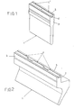
- figure 1 shows in a perspective view a punch carrying the support system according to the present invention;
- figure 2 shows in a perspective view another embodiment of a punch carrying the same support system of figure 1;
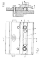
- figure 3 shows in a front view the support system for the punch according to another embodiment;
- figure 4 shows the support system according to section A-A in figure 3.
- With reference to figure 1, 1 designates a punch adapted to be secured through suitable locking means to the upper table of a bending press.
- The punch provides for an horizontal groove or
slot 2 obtained on theupper face 5 of thepunch tang 3. - In the
groove 2, one or morepermanent magnets 4 are housed and are smoothly arranged along the whole or part of the groove. - The groove has a depth that is greater than the magnet thickness, so that the thrust exerted by the press is not discharged onto the magnets that are rather brittle and do not resist to the high compression forces of a bending press.
- As can be noted in figure 1, the magnets wholly occupy the groove obtained on the punch head, while in figure 2 the magnets are spaced and smoothly arranged along the groove.
The magnets are retained into the groove through glueing. - The advantages that the above-described tool offers are evident:
- quick and correct positioning;
- easy direct alignment to bending axis;
- easy and quick cleaning.
-
- The above-described system can also be applied on any already existing tool and on any bending press: it will suffice to obtain a slot in the punch head and to insert the permanent magnets.
- In the embodiment shown, the groove has been made by milling the plane head tool surface, but it could be obtained by screwing two edges to the punch, such edges creating the groove or slot in which the permanent magnets are inserted.
- With reference to figures 3 and 4, a second embodiment of the support system will now be described, such embodiment being particularly advantageous for already marketed tools or punches in order to avoid any type of working on the tools themselves.
- With reference to the above-mentioned figures, 6 points out an intermediate member composed of a plate on the
lower face 7 of which a groove is obtained in which apermanent magnet 8 is inserted, that faces theupper face 5 of a tool, not shown. - On the side face 9 of the plate, two
blind holes 10 are obtained in which twohelical springs 11 are housed, that allow theplate 12 of the locking device to slightly rotate outwards in order to allow a similar punch rotation to enable the punch detachment from the magnet in case of replacement. - The locking device plate is secured with a
socket head screw 13 whose shank passes through a hole with a greater diameter. - The permanent magnet action in fact is such as to oppose a certain resistance to a vertical traction action, while such action can be easily won by a rotation exerted by an operator.
Claims (6)
- Support system of a punch for a bending press characterised in that it comprises one or more permanent magnets (4) interposed between the upper horizontal plane surface (5) of the punch and the punch locking device, said one or more permanent magnets (4) being arranged along the whole or part of said horizontal plane surface.
- Support system for a punch according to claim 1, characterised in that it comprises, on the upper horizontal plane surface of the punch, a groove or slot (2) inside which said one or more permanent magnets (4) are housed.
- Support system for a punch according to claim 1 or 2, characterised in that it comprises two parallel edges applied to the horizontal plane surface to create a groove or slot (2) inside which said one or more permanent magnets (4) are housed.
- Support system for a punch according to claim 1, characterised in that it comprises an intermediate member composed of a plate (6) in which a groove is obtained, said groove being adapted to house one or more permanent magnets, said intermediate member being supported by the tool locking device and being placed above the tool.
- Support system for a punch according to claim 1 or 3, characterised in that it comprises resilient means between intermediate member and locking device, in order to allow a slight rotation of the locking device and consequently of the tool, to make the tool detach from the permanent magnet(s).
- Support system for a punch according to claim 1, 3 or 4, characterised in that the resilient means are composed of helical springs placed in suitable seats obtained in the intermediate member and in the locking device.
Applications Claiming Priority (2)
| Application Number | Priority Date | Filing Date | Title |
|---|---|---|---|
| ITPR20030037 ITPR20030037A1 (en) | 2003-05-23 | 2003-05-23 | SUPPORT SYSTEM OF A PUNCH FOR BENDING PRESS. |
| ITPR20030037 | 2003-05-23 |
Publications (1)
| Publication Number | Publication Date |
|---|---|
| EP1479461A1 true EP1479461A1 (en) | 2004-11-24 |
Family
ID=33042711
Family Applications (1)
| Application Number | Title | Priority Date | Filing Date |
|---|---|---|---|
| EP04012065A Withdrawn EP1479461A1 (en) | 2003-05-23 | 2004-05-21 | Support system for a punch in a bending press |
Country Status (2)
| Country | Link |
|---|---|
| EP (1) | EP1479461A1 (en) |
| IT (1) | ITPR20030037A1 (en) |
Cited By (7)
| Publication number | Priority date | Publication date | Assignee | Title |
|---|---|---|---|---|
| CN106216516A (en) * | 2016-08-08 | 2016-12-14 | 安徽威亚机械制造有限公司 | Press brake die, bending machine and press die method |
| WO2018049056A1 (en) * | 2016-09-09 | 2018-03-15 | Mate Precision Tooling, Inc. | Press brake tool engagement system |
| WO2018071946A3 (en) * | 2016-10-20 | 2018-07-05 | Trumpf Maschinen Austria Gmbh & Co. Kg. | Device for positioning a bending tool |
| WO2019006080A1 (en) * | 2017-06-29 | 2019-01-03 | Mate Precision Tooling, Inc. | Magnetic press brake and machine tooling engagement systems |
| US10953453B2 (en) | 2017-11-06 | 2021-03-23 | Mate Precision Technologies Inc. | Magnetic press brake tooling engagement system |
| US11235370B2 (en) | 2019-04-08 | 2022-02-01 | E&S Enterprises Inc. | Punch assembly with interchangeable tips |
| US12103064B2 (en) | 2019-04-08 | 2024-10-01 | E&S Enterprises Inc. | Punch assembly with interchangeable tips |
Citations (5)
| Publication number | Priority date | Publication date | Assignee | Title |
|---|---|---|---|---|
| US2912249A (en) * | 1955-06-13 | 1959-11-10 | Eckold Walter | Tool clamps |
| JPS5550920A (en) * | 1978-10-06 | 1980-04-14 | Matsushita Electric Ind Co Ltd | Bending device |
| DE19518387A1 (en) * | 1995-05-23 | 1996-11-28 | Dieter Jung | Bench used for bending over edges of sheet metal plates at angle |
| FR2791590A1 (en) * | 1999-03-31 | 2000-10-06 | Michel Brisard | Punch tool mounting for press has magnets to hold tool and tool head together |
| JP2003117607A (en) * | 2001-10-09 | 2003-04-23 | Kitagawa Seisakusho:Kk | Mold for press bending machine |
-
2003
- 2003-05-23 IT ITPR20030037 patent/ITPR20030037A1/en unknown
-
2004
- 2004-05-21 EP EP04012065A patent/EP1479461A1/en not_active Withdrawn
Patent Citations (5)
| Publication number | Priority date | Publication date | Assignee | Title |
|---|---|---|---|---|
| US2912249A (en) * | 1955-06-13 | 1959-11-10 | Eckold Walter | Tool clamps |
| JPS5550920A (en) * | 1978-10-06 | 1980-04-14 | Matsushita Electric Ind Co Ltd | Bending device |
| DE19518387A1 (en) * | 1995-05-23 | 1996-11-28 | Dieter Jung | Bench used for bending over edges of sheet metal plates at angle |
| FR2791590A1 (en) * | 1999-03-31 | 2000-10-06 | Michel Brisard | Punch tool mounting for press has magnets to hold tool and tool head together |
| JP2003117607A (en) * | 2001-10-09 | 2003-04-23 | Kitagawa Seisakusho:Kk | Mold for press bending machine |
Non-Patent Citations (2)
| Title |
|---|
| PATENT ABSTRACTS OF JAPAN vol. 0040, no. 92 (M - 018) 3 July 1980 (1980-07-03) * |
| PATENT ABSTRACTS OF JAPAN vol. 2003, no. 08 6 August 2003 (2003-08-06) * |
Cited By (14)
| Publication number | Priority date | Publication date | Assignee | Title |
|---|---|---|---|---|
| CN106216516B (en) * | 2016-08-08 | 2018-09-11 | 安徽威亚机械制造有限公司 | Press brake die and bending machine |
| CN106216516A (en) * | 2016-08-08 | 2016-12-14 | 安徽威亚机械制造有限公司 | Press brake die, bending machine and press die method |
| US11383284B2 (en) | 2016-09-09 | 2022-07-12 | Mate Precision Technologies Inc. | Press brake tool engagement system |
| WO2018049056A1 (en) * | 2016-09-09 | 2018-03-15 | Mate Precision Tooling, Inc. | Press brake tool engagement system |
| WO2018071946A3 (en) * | 2016-10-20 | 2018-07-05 | Trumpf Maschinen Austria Gmbh & Co. Kg. | Device for positioning a bending tool |
| US11491530B2 (en) | 2016-10-20 | 2022-11-08 | Trumpf Maschinen Austria Gmbh & Co. Kg | Device for positioning a bending tool |
| CN109922900A (en) * | 2016-10-20 | 2019-06-21 | 特鲁普机械奥地利有限公司及两合公司 | Device for positioning bending tools |
| CN109922900B (en) * | 2016-10-20 | 2020-11-20 | 特鲁普机械奥地利有限公司及两合公司 | Methods of Positioning the Bending Tool |
| US11471927B2 (en) | 2016-10-20 | 2022-10-18 | Trumpf Maschinen Austria Gmbh & Co. Kg | Loading method for a machine tool and tool transfer device |
| US10792716B2 (en) | 2017-06-29 | 2020-10-06 | Mate Precision Tooling, Inc. | Magnetic press brake and machine tooling engagement systems |
| WO2019006080A1 (en) * | 2017-06-29 | 2019-01-03 | Mate Precision Tooling, Inc. | Magnetic press brake and machine tooling engagement systems |
| US10953453B2 (en) | 2017-11-06 | 2021-03-23 | Mate Precision Technologies Inc. | Magnetic press brake tooling engagement system |
| US11235370B2 (en) | 2019-04-08 | 2022-02-01 | E&S Enterprises Inc. | Punch assembly with interchangeable tips |
| US12103064B2 (en) | 2019-04-08 | 2024-10-01 | E&S Enterprises Inc. | Punch assembly with interchangeable tips |
Also Published As
| Publication number | Publication date |
|---|---|
| ITPR20030037A1 (en) | 2004-11-24 |
Similar Documents
| Publication | Publication Date | Title |
|---|---|---|
| US5181438A (en) | Ball lock punch retainer | |
| US20050188797A1 (en) | Connecting shaft device for screws | |
| KR101624099B1 (en) | jig assembly for processing a oil-groove | |
| EP1479461A1 (en) | Support system for a punch in a bending press | |
| US12544820B2 (en) | Punching tool for mobile use | |
| JP2005021935A (en) | Locate clamp device | |
| US10343261B2 (en) | Vise stop arrangement | |
| KR102901273B1 (en) | Quick Change System | |
| CN102762325A (en) | Tool for machining and method of orientation of cutting inserts in the tool | |
| BRPI0612308A2 (en) | top folding drive and tool clamping device | |
| US20070186384A1 (en) | Wall frame hanging apparatus | |
| US2912249A (en) | Tool clamps | |
| US20080182738A1 (en) | Robotic end-of-arm tool quick-change device | |
| KR20180006540A (en) | Rail drilling apparatus | |
| US10773293B2 (en) | Hydraulic punch device | |
| US8485482B2 (en) | Retaining system | |
| KR200444042Y1 (en) | Positioning Device for Nozzle | |
| KR20100125066A (en) | Jig device | |
| US7224251B2 (en) | Magnetic retaining device for machine tool | |
| EP1321200B1 (en) | Sheet metal working machine with a tool | |
| JP3124434U (en) | Snap fastener attaching machine | |
| CN113784817A (en) | Quick change system, rotary indexing table with this type of quick change system and use | |
| CN211491319U (en) | Locating pin press-fitting machine | |
| JPH09220618A (en) | Upper mold device for V-shaped bending machine | |
| CN213135099U (en) | Valve body punching clamp |
Legal Events
| Date | Code | Title | Description |
|---|---|---|---|
| PUAI | Public reference made under article 153(3) epc to a published international application that has entered the european phase |
Free format text: ORIGINAL CODE: 0009012 |
|
| AK | Designated contracting states |
Kind code of ref document: A1 Designated state(s): AT BE BG CH CY CZ DE DK EE ES FI FR GB GR HU IE IT LI LU MC NL PL PT RO SE SI SK TR |
|
| AX | Request for extension of the european patent |
Extension state: AL HR LT LV MK |
|
| AKX | Designation fees paid | ||
| REG | Reference to a national code |
Ref country code: DE Ref legal event code: 8566 |
|
| STAA | Information on the status of an ep patent application or granted ep patent |
Free format text: STATUS: THE APPLICATION IS DEEMED TO BE WITHDRAWN |
|
| 18D | Application deemed to be withdrawn |
Effective date: 20050525 |