EP3508806A2 - Method for manufacturing a curved heat exchanger using wedge shaped segments - Google Patents
Method for manufacturing a curved heat exchanger using wedge shaped segments Download PDFInfo
- Publication number
- EP3508806A2 EP3508806A2 EP18204860.3A EP18204860A EP3508806A2 EP 3508806 A2 EP3508806 A2 EP 3508806A2 EP 18204860 A EP18204860 A EP 18204860A EP 3508806 A2 EP3508806 A2 EP 3508806A2
- Authority
- EP
- European Patent Office
- Prior art keywords
- section
- heat exchanger
- lengthwise
- widthwise
- closure
- Prior art date
- Legal status (The legal status is an assumption and is not a legal conclusion. Google has not performed a legal analysis and makes no representation as to the accuracy of the status listed.)
- Granted
Links
Images




Classifications
-
- F—MECHANICAL ENGINEERING; LIGHTING; HEATING; WEAPONS; BLASTING
- F28—HEAT EXCHANGE IN GENERAL
- F28F—DETAILS OF HEAT-EXCHANGE AND HEAT-TRANSFER APPARATUS, OF GENERAL APPLICATION
- F28F3/00—Plate-like or laminated elements; Assemblies of plate-like or laminated elements
- F28F3/02—Elements or assemblies thereof with means for increasing heat-transfer area, e.g. with fins, with recesses, with corrugations
- F28F3/025—Elements or assemblies thereof with means for increasing heat-transfer area, e.g. with fins, with recesses, with corrugations the means being corrugated, plate-like elements
-
- B—PERFORMING OPERATIONS; TRANSPORTING
- B23—MACHINE TOOLS; METAL-WORKING NOT OTHERWISE PROVIDED FOR
- B23K—SOLDERING OR UNSOLDERING; WELDING; CLADDING OR PLATING BY SOLDERING OR WELDING; CUTTING BY APPLYING HEAT LOCALLY, e.g. FLAME CUTTING; WORKING BY LASER BEAM
- B23K1/00—Soldering, e.g. brazing, or unsoldering
- B23K1/0008—Soldering, e.g. brazing, or unsoldering specially adapted for particular articles or work
- B23K1/0012—Brazing of heat exchangers
-
- F—MECHANICAL ENGINEERING; LIGHTING; HEATING; WEAPONS; BLASTING
- F28—HEAT EXCHANGE IN GENERAL
- F28D—HEAT-EXCHANGE APPARATUS, NOT PROVIDED FOR IN ANOTHER SUBCLASS, IN WHICH THE HEAT-EXCHANGE MEDIA DO NOT COME INTO DIRECT CONTACT
- F28D1/00—Heat-exchange apparatus having stationary conduit assemblies for one heat-exchange medium only, the media being in contact with different sides of the conduit wall, in which the other heat-exchange medium is a large body of fluid, e.g. domestic or motor car radiators
- F28D1/02—Heat-exchange apparatus having stationary conduit assemblies for one heat-exchange medium only, the media being in contact with different sides of the conduit wall, in which the other heat-exchange medium is a large body of fluid, e.g. domestic or motor car radiators with heat-exchange conduits immersed in the body of fluid
- F28D1/0246—Heat-exchange apparatus having stationary conduit assemblies for one heat-exchange medium only, the media being in contact with different sides of the conduit wall, in which the other heat-exchange medium is a large body of fluid, e.g. domestic or motor car radiators with heat-exchange conduits immersed in the body of fluid heat-exchange elements having several adjacent conduits forming a whole, e.g. blocks
-
- F—MECHANICAL ENGINEERING; LIGHTING; HEATING; WEAPONS; BLASTING
- F28—HEAT EXCHANGE IN GENERAL
- F28D—HEAT-EXCHANGE APPARATUS, NOT PROVIDED FOR IN ANOTHER SUBCLASS, IN WHICH THE HEAT-EXCHANGE MEDIA DO NOT COME INTO DIRECT CONTACT
- F28D1/00—Heat-exchange apparatus having stationary conduit assemblies for one heat-exchange medium only, the media being in contact with different sides of the conduit wall, in which the other heat-exchange medium is a large body of fluid, e.g. domestic or motor car radiators
- F28D1/02—Heat-exchange apparatus having stationary conduit assemblies for one heat-exchange medium only, the media being in contact with different sides of the conduit wall, in which the other heat-exchange medium is a large body of fluid, e.g. domestic or motor car radiators with heat-exchange conduits immersed in the body of fluid
- F28D1/04—Heat-exchange apparatus having stationary conduit assemblies for one heat-exchange medium only, the media being in contact with different sides of the conduit wall, in which the other heat-exchange medium is a large body of fluid, e.g. domestic or motor car radiators with heat-exchange conduits immersed in the body of fluid with tubular conduits
- F28D1/053—Heat-exchange apparatus having stationary conduit assemblies for one heat-exchange medium only, the media being in contact with different sides of the conduit wall, in which the other heat-exchange medium is a large body of fluid, e.g. domestic or motor car radiators with heat-exchange conduits immersed in the body of fluid with tubular conduits the conduits being straight
- F28D1/0535—Heat-exchange apparatus having stationary conduit assemblies for one heat-exchange medium only, the media being in contact with different sides of the conduit wall, in which the other heat-exchange medium is a large body of fluid, e.g. domestic or motor car radiators with heat-exchange conduits immersed in the body of fluid with tubular conduits the conduits being straight the conduits having a non-circular cross-section
- F28D1/05366—Assemblies of conduits connected to common headers, e.g. core type radiators
-
- F—MECHANICAL ENGINEERING; LIGHTING; HEATING; WEAPONS; BLASTING
- F28—HEAT EXCHANGE IN GENERAL
- F28D—HEAT-EXCHANGE APPARATUS, NOT PROVIDED FOR IN ANOTHER SUBCLASS, IN WHICH THE HEAT-EXCHANGE MEDIA DO NOT COME INTO DIRECT CONTACT
- F28D7/00—Heat-exchange apparatus having stationary tubular conduit assemblies for both heat-exchange media, the media being in contact with different sides of a conduit wall
- F28D7/005—Heat-exchange apparatus having stationary tubular conduit assemblies for both heat-exchange media, the media being in contact with different sides of a conduit wall the conduits for only one medium being tubes having bent portions or being assembled from bent tubes or being tubes having a toroidal configuration
-
- F—MECHANICAL ENGINEERING; LIGHTING; HEATING; WEAPONS; BLASTING
- F28—HEAT EXCHANGE IN GENERAL
- F28D—HEAT-EXCHANGE APPARATUS, NOT PROVIDED FOR IN ANOTHER SUBCLASS, IN WHICH THE HEAT-EXCHANGE MEDIA DO NOT COME INTO DIRECT CONTACT
- F28D9/00—Heat-exchange apparatus having stationary plate-like or laminated conduit assemblies for both heat-exchange media, the media being in contact with different sides of a conduit wall
- F28D9/0025—Heat-exchange apparatus having stationary plate-like or laminated conduit assemblies for both heat-exchange media, the media being in contact with different sides of a conduit wall the conduits being formed by zig-zag bend plates
-
- F—MECHANICAL ENGINEERING; LIGHTING; HEATING; WEAPONS; BLASTING
- F28—HEAT EXCHANGE IN GENERAL
- F28D—HEAT-EXCHANGE APPARATUS, NOT PROVIDED FOR IN ANOTHER SUBCLASS, IN WHICH THE HEAT-EXCHANGE MEDIA DO NOT COME INTO DIRECT CONTACT
- F28D9/00—Heat-exchange apparatus having stationary plate-like or laminated conduit assemblies for both heat-exchange media, the media being in contact with different sides of a conduit wall
- F28D9/0062—Heat-exchange apparatus having stationary plate-like or laminated conduit assemblies for both heat-exchange media, the media being in contact with different sides of a conduit wall the conduits for one heat-exchange medium being formed by spaced plates with inserted elements
-
- F—MECHANICAL ENGINEERING; LIGHTING; HEATING; WEAPONS; BLASTING
- F28—HEAT EXCHANGE IN GENERAL
- F28F—DETAILS OF HEAT-EXCHANGE AND HEAT-TRANSFER APPARATUS, OF GENERAL APPLICATION
- F28F9/00—Casings; Header boxes; Auxiliary supports for elements; Auxiliary members within casings
- F28F9/26—Arrangements for connecting different sections of heat-exchange elements, e.g. of radiators
-
- F—MECHANICAL ENGINEERING; LIGHTING; HEATING; WEAPONS; BLASTING
- F28—HEAT EXCHANGE IN GENERAL
- F28D—HEAT-EXCHANGE APPARATUS, NOT PROVIDED FOR IN ANOTHER SUBCLASS, IN WHICH THE HEAT-EXCHANGE MEDIA DO NOT COME INTO DIRECT CONTACT
- F28D21/00—Heat-exchange apparatus not covered by any of the groups F28D1/00 - F28D20/00
- F28D2021/0019—Other heat exchangers for particular applications; Heat exchange systems not otherwise provided for
- F28D2021/0021—Other heat exchangers for particular applications; Heat exchange systems not otherwise provided for for aircrafts or cosmonautics
-
- F—MECHANICAL ENGINEERING; LIGHTING; HEATING; WEAPONS; BLASTING
- F28—HEAT EXCHANGE IN GENERAL
- F28F—DETAILS OF HEAT-EXCHANGE AND HEAT-TRANSFER APPARATUS, OF GENERAL APPLICATION
- F28F2210/00—Heat exchange conduits
- F28F2210/10—Particular layout, e.g. for uniform temperature distribution
-
- F—MECHANICAL ENGINEERING; LIGHTING; HEATING; WEAPONS; BLASTING
- F28—HEAT EXCHANGE IN GENERAL
- F28F—DETAILS OF HEAT-EXCHANGE AND HEAT-TRANSFER APPARATUS, OF GENERAL APPLICATION
- F28F2240/00—Spacing means
Definitions
- the present disclosure relates to heat exchangers, and in particular to curved plate-fin heat exchangers.
- Heat exchangers are often used to transfer heat between two fluids.
- heat exchangers may be used to transfer heat between a relatively hot air source (e.g., bleed air from a gas turbine engine) and a relatively cool air source (e.g., ram air).
- a relatively hot air source e.g., bleed air from a gas turbine engine
- a relatively cool air source e.g., ram air.
- Some heat exchangers often referred to as plate-fin heat exchangers, include a plate-fin core having multiple heat transfer sheets arranged in layers to define air passages there between. Closure bars seal alternating inlets of hot air and cool air inlet sides of the core. Accordingly, hot air and cool air are directed through alternating passages to form alternating layers of hot and cool air within the core. Heat is transferred between the hot and cool air via the heat transfer sheets that separate the layers.
- each of the passages can include heat transfer fins, often formed of corrugated material (e.g., aluminum), that are oriented in a direction of the flow within the passage.
- the heat transfer fins increase turbulence and a surface area that is exposed to the airflow, thereby enhancing heat transfer between the layers.
- plate-fin heat exchangers Due to existing corrugated sheet structures and manufacturing techniques, known plate-fin heat exchangers have a rectangular axial cross section. In some applications, such as aircraft environmental control systems, the plate-fin heat exchangers are arranged around a central axis. As a result of the rectangular cross section of the plate-fin heat exchangers, gaps occur between adjacent plate-fin heat exchangers and between a curved housing and the plate-fin heat exchangers when the plate-fin heat exchangers are arranged circumferentially about the central axis. These gaps create dead space next to the plate-fin heat exchangers that cannot be used by the plate-fin heat exchangers.
- a heat exchanger in one embodiment, includes a first section with a top side opposite a bottom side, wherein the top side is longer than the bottom side.
- the first section also includes a first side extending between the top side and the bottom side, and a second side extending between the top side and the bottom side opposite the first side.
- the first side and the second side of the first section taper toward each other as the first side and the second side extend toward the bottom side of the first section.
- the heat exchanger also includes a second section with a top side opposite a bottom side, and a first side extending between the top side of the second section and the bottom side of the second section.
- the second section also includes a second side extending between the top side of the second section and the bottom side of the second section opposite the first side of the second section.
- the second side of the second section of the heat exchanger is connected to the first side of the first section of the heat exchanger.
- a header manifold is connected to the first side of the second section.
- a heat exchanger in another embodiment, includes a first section with a top opposite a bottom, a lengthwise dimension transverse to a widthwise dimension, and a first parting sheet at the top of the first section.
- the first section also includes a first lengthwise closure bar and a second lengthwise closure bar under the first parting sheet, with the first and second lengthwise closure bars extending in the lengthwise dimension and spaced from each other in the widthwise dimension.
- a second parting sheet is under the first and second lengthwise closure bars. The first parting sheet, the second parting sheet, the first lengthwise closure bar, and the second lengthwise closure bar together form a first lengthwise passage that extends in the lengthwise dimension through the first section of the heat exchanger.
- a first widthwise closure bar and a second widthwise closure bar are under the second parting sheet.
- the first and second widthwise closure bars extend in the widthwise dimension and are spaced from each other in the lengthwise dimension.
- a third parting sheet is under the first and second widthwise closure bars.
- the second parting sheet, the third parting sheet, the first widthwise closure bar, and the second widthwise closure bar together form a first widthwise passage that extends in the widthwise dimension through the first section of the heat exchanger.
- a third lengthwise closure bar and a fourth lengthwise closure bar are under the third parting sheet and extend in the lengthwise dimension and are spaced from each other in the widthwise dimension.
- a fourth parting sheet is under the third and fourth lengthwise closure bars.
- the third parting sheet, the fourth parting sheet, the third lengthwise closure bar, and the fourth lengthwise closure bar together form a second lengthwise passage that extends in the lengthwise dimension through the first section of the heat exchanger.
- the first and second lengthwise closure bars of the first section are both longer than the third and fourth lengthwise closure bars of the first section.
- a method for manufacturing a heat exchanger includes stacking a plurality of parting sheets, a plurality of lengthwise closure bars, and a plurality of widthwise closure bars to form a rectangular first heat exchanger section.
- the first heat exchanger section includes at least one widthwise passage extending between a pair of the widthwise closure bars and at least one lengthwise passage extending between a pair of the lengthwise closure bars.
- the method also includes brazing the rectangular first heat exchanger section together and cutting a first side and a second end of the rectangular first heat exchanger section to give the first heat exchanger section a tapered-trapezoid profile.
- the method further includes stacking a second plurality of parting sheets, a second plurality of lengthwise closure bars, and a second plurality of widthwise closure bars to form a second heat exchanger section.
- the second heat exchanger section includes at least one widthwise passage extending between a pair of the second plurality of widthwise closure bars and at least one lengthwise passage extending between a pair of the second plurality of lengthwise closure bars.
- the method further includes brazing the second heat exchanger section together, and brazing an end of the second heat exchanger section to the first or second end of the first heat exchanger section.
- the disclosure relates to a heat exchanger with multiple core sections. At least one of the core sections of the heat exchanger is wedge-shaped (i.e., tapered on two sides). When the wedge-shaped core section(s) is connected to adjacent core sections in the heat exchanger, the interface between the tapered sides of the wedge-shaped core section(s) and the adjacent core sections creates a bend (or bends) in the overall geometry of the heat exchanger. The bend(s) in the heat exchanger allow the heat exchanger to curve and better fill and utilize non-rectangular spaces.
- the disclosure also relates to a method for manufacturing this heat exchanger. The bent heat exchanger is described below with reference to FIGS. 1-4 .
- FIG. 1 is a perspective view of heat exchanger 10.
- heat exchanger 10 includes first header 12a, second header 12b, and core 14 with first section 14a, second section 14b, and third section 14c.
- First header 12a includes inlet 16 and second header 12b includes outlet 18.
- First section 14a of core 14 includes top side 20a, bottom side 22a, first side 24a, and second side 26a.
- Second section 14b of core 14 includes top side 20b, bottom side 22b, first side 24b, and second side 26b.
- Third section 14c of core 14 includes top side 20c, bottom side 22c, first side 24c, and second side 26c.
- Heat exchanger 10 also includes first bend 28 and second bend 30. Hot air F1 and cool air F2 interact with heat exchanger 10.
- Top side 20a of first section 14a is positioned opposite bottom side 22a.
- First side 24a of first section 14a is positioned opposite second side 26a, and both first side 24a and second side 26a of first section 14a extend from top side 20a to bottom side 22a.
- Top side 20a is longer than bottom side 22a, causing first side 24a and second side 26a to taper toward each other as they extend to bottom side 22a.
- second section 14b of core 14 is identical to first section 14a, except that first side 24b of second section 14b is not tapered.
- Top side 20b of second section 14b is positioned opposite bottom side 22b.
- First side 24b of second section 14b is positioned opposite second side 26b, and both first side 24b and second side 26b of second section 14b extend from top side 20b to bottom side 22b.
- Top side 20b is longer than bottom side 22b, second side 26b to taper as second side 26b extends to bottom side 22b.
- third section 14c of core 14 is also identical to first section 14a, except that second side 26c of third section 14c is not tapered.
- Top side 20c of third section 14c is positioned opposite bottom side 22c.
- First side 24c of third section 14c is positioned opposite second side 26c, and both first side 24c and second side 26c of third section 14c extend from top side 20c to bottom side 22c.
- Top side 20c is longer than bottom side 22c, causing first side 24c to taper as first side 24c extends to bottom side 22c.
- Third section 14c, first section 14a, and second section 14b of core 14 are connected in series between first header 12a and second header 12b.
- first header 12a is connected to first side 24b of second section 14b.
- Second side 26b of second section 14b is connected to first side 24a of first section 14a.
- Second side 26a of first section 14a is connected to first side 24c of third section 14c.
- Second side 26c of third section 14c is connected to second header 12b.
- First section 14a, second section 14b, and third section 14c of core 14 are brazed together to form core 14.
- First header 12a and second header 12b are welded to core 14 to form heat exchanger 10.
- first bend 28 occurs in heat exchanger 10 between first section 14a and second section 14b of core 14
- second bend 30 occurs between first section 14a and third section 14c of core 14.
- First bend 28 and second bend 30 in heat exchanger 10 cause heat exchanger 10 to arc and curve from first header 12a to second header 12b. Because heat exchanger 10 arcs and curves from first header 12a to second header 12b, heat exchanger 10 can be used in curved spaces, such as curved or annular ducts in aircraft environmental control systems.
- heat exchanger 10 During operation of heat exchanger 10, hot air F1 enters inlet 16 on first header 12a where first header 12a directs hot air F1 in second section 14b of core 14.
- heat exchanger 10 is a plate-fin heat exchanger with lengthwise passages that extend completely through second section 14b, first section 14a, and third section 14c so that hot air F1 is able to flow from first header 12a, through core 14, and into second header 12b.
- hot air F1 exits heat exchanger 10 through outlet 18 of second header 12b.
- first section 14a, second section 14b, and third section 14c of core 14 each include widthwise passages that allow cool air F2 to flow orthogonally through core 14 without mixing with hot air F1.
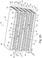
- FIG. 2A is a perspective view of first section 14a of core 14 of heat exchanger 10.
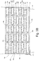
- FIG. 2B is a side elevation view of first section 14a of core 14 of heat exchanger 10 from FIG. 2A . While FIGS. 2A and 2B illustrate first section 14a of core 14, the following discussion of FIGS. 2A and 2B can be adapted and applied to second section 14b and third section 14c of core 14. As shown in FIGS.
- first section 14a further includes parting sheets 32a-32j, lengthwise closure bars 34a-34e, widthwise closure bars 36a-36d, hot-gas passages 38a-38e, cool-gas passages 40a-40d, lengthwise corrugated sheets 42a-42e, widthwise corrugated sheets 44a-44d, top end sheet 46a, and bottom end sheet 48a.
- a lengthwise dimension X of first section 14a is defined as the direction parallel to the x-axis
- a widthwise dimension Z of first section 14a is defined as the direction parallel to the z-axis
- a height dimension Y of first section 14a is defined as the direction parallel to the y-axis.
- first section 14a the elements of first section 14a are stacked in the height dimension Y in the following order, descending from top side 20a to bottom side 22a of first section 14a: top end sheet 46a, parting sheet 32a, lengthwise closure bars 34a (two shown), lengthwise corrugation 42a, parting sheet 32b, widthwise closure bars 36a (two shown), widthwise corrugation 44a, parting sheet 32c, lengthwise closure bars 34b (two shown), lengthwise corrugation 42b, parting sheet 32d, widthwise closure bars 36b (two shown), widthwise corrugation 44b, parting sheet 32e, lengthwise closure bars 34c (two shown), lengthwise corrugation 42c, parting sheet 32f, widthwise closure bars 36c (two shown), widthwise corrugation 44c, parting sheet 32g, lengthwise closure bars 34d (two shown), lengthwise corrugation 42d, parting sheet 32h, widthwise closure bars 36d (two shown), widthwise corrugation 44d, parting sheet 32i, lengthwise closure bars 34
- Hot-gas passages 38a-38e are passages that extend in the lengthwise dimension X through first section 14a.
- Hot-gas passages 38a-38e are formed by lengthwise closure bars 34a-34e and parting sheets 32a-32j.
- parting sheet 32a, parting sheet 32b, lengthwise corrugation 42a, and lengthwise closure bars 34a form hot-gas passage 38a.
- Parting sheet 32c, parting sheet 32d, lengthwise corrugation 42b, and lengthwise closure bars 34b form hot-gas passage 38b.
- Parting sheet 32e, parting sheet 32f, lengthwise corrugation 42c, and lengthwise closure bars 34c form hot-gas passage 38c.
- Parting sheet 32g, parting sheet 32h, lengthwise corrugation 42d, and lengthwise closure bars 34d form hot-gas passage 38d.
- Parting sheet 32i, parting sheet 32j, lengthwise corrugation 42e, and lengthwise closure bars 34e form hot-gas passage 38e.
- Cool-gas passages 40a-40d are passages that extend in the widthwise dimension Z through first section 14a. Cool-gas passages 40a-40d are formed by widthwise closure bars 36a-36d and parting sheets 32b-32i. For example, parting sheet 32b, parting sheet 32c, widthwise corrugation 44a, and widthwise closure bars 36a form cool-gas passage 40a. Parting sheet 32d, parting sheet 32e, widthwise corrugation 44b, and widthwise closure bars 36b form cool-gas passage 40b.
- Parting sheet 32f, parting sheet 32g, widthwise corrugation 44c, and widthwise closure bars 36c form cool-gas passage 40c.
- Parting sheet 32h, parting sheet 32i, widthwise corrugation 44d, and widthwise closure bars 36d form cool-gas passage 40d.
- first section 14a in FIGS. 2A and 2B alternates hot-gas passages 38a-38e with cool-gas passages 40a-40d along the height dimension Y such that each one of cool-gas passages 40a-40d is positioned vertically on first section 14a between two of hot-gas passages 38a-38e. Alternating hot-gas passages 38a-38e with cool-gas passages 40a-40d improves the efficiency of first section 14a of heat exchanger 10 by increasing the heat transfer area between hot air F1 and cool air F2.
- lengthwise corrugated sheets 42a-42e are positioned inside hot-gas passages 38a-38e respectively, and widthwise corrugated sheets 44a-44d are positioned inside cool-gas passages 40a-40d respectively.
- Lengthwise corrugated sheets 42a-42e extend the entire length of hot-gas passages 38a-38e respectively, and widthwise corrugated sheets 44a-44d extend the entire length of cool-gas passages 40a-40d respectively.
- first section 14a of core 14 is tapered with top side 20a longer than bottom side 22a, and first side 24a and second side 26a tapering toward each other as they extend to bottom side 22a of first section 14a.
- FIG. 2B best illustrates the tapered profile of first section 14a.
- lengthwise closure bars 34a-34e decrease in length in the X dimension from top side 20a to bottom side 22a.
- the two lengthwise closure bars 34a are longer in the X dimension than the two lengthwise closure bars 34b.
- Lengthwise closure bars 34e have the shortest length among lengthwise closure bars 34a-34e.
- Parting sheets 32a-32j also decrease in length in the X dimension from top side 20a to bottom side 22a. For example, parting sheet 32a is longer than parting sheet 32b in the X dimension, and parting sheet 32b is longer than parting sheet 32c in the X dimension. Parting sheet 32j has the shortest length of parting sheets 32a-32j in the X dimension.
- each of widthwise closure bars 36a-36d includes a ramping trapezoid cross-section on the X-Y plane with two ninety-degree angles, one obtuse angle, and one acute angle.
- Each of lengthwise closure bars 34a-34e include a rectangular cross-section on the Y-Z plane and an elongated isosceles trapezoid profile on the X-Y plane.
- first section 14a of core 14 shown in FIG. 1
- a method for manufacturing first section 14a (as well as second section 14b and third section 14c) and heat exchanger 10 is described below with reference to FIGS. 3A-4 .
- FIG. 3A is a perspective view of a prefinished embodiment of first section 14a of core 14 (shown in FIG. 1 ) for heat exchanger 10 (also shown in FIG. 1 ).
- FIG. 3B is a side elevation view of the prefinished embodiment of first section 14a from FIG. 3A .
- FIG. 4 is a side elevation view of a completed embodiment of heat exchanger 10. While FIGS. 3A and 3B illustrate first section 14a, the following discussion of FIGS. 3A and 3B can also be applied to second section 14b and third section 14c of core 14.
- first section 14a To manufacture first section 14a, the elements of first section 14a are stacked in the height dimension Y in the following order, descending from top side 20a to bottom side 22a of first section 14a: top end sheet 46a, parting sheet 32a, lengthwise closure bars 34a, parting sheet 32b, widthwise closure bars 36a, parting sheet 32c, lengthwise closure bars 34b, parting sheet 32d, widthwise closure bars 36b, parting sheet 32e, lengthwise closure bars 34c, parting sheet 32f, widthwise closure bars 36c, parting sheet 32g, lengthwise closure bars 34d, parting sheet 32h, widthwise closure bars 36d, parting sheet 32i, lengthwise closure bars 34e, parting sheet 32j, and bottom end sheet 48a.
- lengthwise corrugated sheets 42a-42e are inserted inside hot-gas passages 38a-38e respectively, and widthwise corrugated sheets 44a-44d are inserted inside cool-gas passages 40a-40d respectively.
- Widthwise closure bars 36a-36d have differing thicknesses in the X dimension, with the thickness of widthwise closure bars 36a-36d increasing from widthwise closure bars 36a down to widthwise closure bars 36d.
- widthwise closure bars 36a are each thinner in the X dimension than widthwise closure bars 36b, and widthwise closure bars 36b are thinner in the X dimension than widthwise closure bars 36c.
- Widthwise closure bars 36d are the thickest of widthwise closure bars 36a-36d.
- prefinished first section 14a After stacking parting sheets 32a-32j, lengthwise closure bars 34a-34e, widthwise closure bars 36a-36d, lengthwise corrugated sheets 42a-42e, widthwise corrugated sheets 44a-44d, top end sheet 46a, and bottom end sheet 48a as described above, the above listed elements are brazed together into a rectangular prefinished first section 14a using a first braze material at a first temperature. After the elements of prefinished first section 14 are brazed together, the ends of prefinished first section 14 are cut along lines L1 and L2 to form tapered first side 24a and tapered second side 26a and give first section 14a a tapered-trapezoid profile.
- the cuts along lines L1 and L2 are accommodated by the increasing thicknesses of widthwise closure bars 36a-36d.
- the cuts along lines L1 and L2 can be performed through wire-cut electrical discharge machining (EDM).
- EDM electrical discharge machining
- the above steps used to produce tapered first section 14a of core section 14 are repeated to produce second section 14b (shown above in FIG. 1 and below in FIG. 4 ) and to produce third section 14c (shown above in FIG. 1 and below in FIG. 4 ). Because first side 24b of second section 14b and second side 26c of third section 14c are both not tapered (as discussed previously with reference to FIG. 1 ), second section 14b and third section 14c each only require one angled cut.
- first section 14a, second section 14b, and third section 14c After manufacturing first section 14a, second section 14b, and third section 14c, the three sections 14a, 14b, and 14c are positioned relative one another such that hot-gas passages 38a-38e of first section 14a are contiguous with hot-gas passages 38a-38e of second section 14b and third section 14c respectively, as shown in FIG. 4 .
- First section 14a, second section 14b, and third section 14c are then brazed together to form core 14 using a second braze material at a second temperature.
- the second braze material has a lower melting temperature than the first braze material, and thus the second temperature is lower than the first temperature.
- first section 14a, second section 14b, and third section 14c are brazed at a lower temperature than the first brazing temperature used to produce sections 14a, 14b, and 14c, first section 14a, second section 14b, and/or third section 14c are not at risk of individually falling apart during the second braze.
- First header 12a and second header 12b are then positioned relative core 14 and welded to core 14.
- first header manifold 12a is welded to first side 24b of second section 14b.
- Second side 26b of second section 14b is connected by the second braze material to first side 24a of first section 14b.
- Second side 26a of first section 14a is connected by the second braze material to first side 24c of third section 14c.
- Second side 26c of third section 14c is welded to second header 12b.
- first bend 28 and second bend 30 are formed in core 14 of heat exchanger 10.
- First bend 28 and second bend 30 in heat exchanger 10 cause heat exchanger 10 to arc and curve from first header 12a to second header 12b. Because heat exchanger 10 arcs and curves from first header 12a to second header 12b, heat exchanger 10 can be used in curved spaces, such as curved or annular ducts in aircraft environmental control systems.
- a heat exchanger in one embodiment, includes a first section with a top side opposite a bottom side, wherein the top side is longer than the bottom side.
- the first section also includes a first side extending between the top side and the bottom side, and a second side extending between the top side and the bottom side opposite the first side.
- the first side and the second side of the first section taper toward each other as the first side and the second side extend toward the bottom side of the first section.
- the heat exchanger also includes a second section with a top side opposite a bottom side, and a first side extending between the top side of the second section and the bottom side of the second section.
- the second section also includes a second side extending between the top side of the second section and the bottom side of the second section opposite the first side of the second section.
- the second side of the second section of the heat exchanger is connected to the first side of the first section of the heat exchanger.
- a header manifold is connected to the first side of the second section.
- the heat exchanger of the preceding paragraph can optionally include, additionally and/or alternatively, any one or more of the following features, configurations and/or additional components:
- the top side of the second section is longer than the bottom side of the second section, and the first side of the second section and/or the second side of the second section taper from the top side of the second section to the bottom side of the second section; a first hot-gas passage extending from the first side of the first section to the second side of the first section; and a second hot-gas passage extending from the first side of the second section to the second side of the second section, wherein the second hot-gas passage of the second section is contiguous with the first hot-gas passage of the first section; and/or a first corrugated sheet inside the first hot-gas passage of the first section and extending from the first side of the first section to the second side of the first section; and a second corrugated sheet inside the second hot-gas passage of the second section and extending from the first side of the second section to the second side of the second section.
- a heat exchanger in another embodiment, includes a first section with a top opposite a bottom, a lengthwise dimension transverse to a widthwise dimension, and a first parting sheet at the top of the first section.
- the first section also includes a first lengthwise closure bar and a second lengthwise closure bar under the first parting sheet, with the first and second lengthwise closure bars extending in the lengthwise dimension and spaced from each other in the widthwise dimension.
- a second parting sheet is under the first and second lengthwise closure bars. The first parting sheet, the second parting sheet, the first lengthwise closure bar, and the second lengthwise closure bar together form a first lengthwise passage that extends in the lengthwise dimension through the first section of the heat exchanger.
- a first widthwise closure bar and a second widthwise closure bar are under the second parting sheet.
- the first and second widthwise closure bars extend in the widthwise dimension and are spaced from each other in the lengthwise dimension.
- a third parting sheet is under the first and second widthwise closure bars.
- the second parting sheet, the third parting sheet, the first widthwise closure bar, and the second widthwise closure bar together form a first widthwise passage that extends in the widthwise dimension through the first section of the heat exchanger.
- a third lengthwise closure bar and a fourth lengthwise closure bar are under the third parting sheet and extend in the lengthwise dimension and are spaced from each other in the widthwise dimension.
- a fourth parting sheet is under the third and fourth lengthwise closure bars.
- the third parting sheet, the fourth parting sheet, the third lengthwise closure bar, and the fourth lengthwise closure bar together form a second lengthwise passage that extends in the lengthwise dimension through the first section of the heat exchanger.
- the first and second lengthwise closure bars of the first section are both longer than the third and fourth lengthwise closure bars of the first section.
- the heat exchanger of the preceding paragraph can optionally include, additionally and/or alternatively, any one or more of the following features, configurations and/or additional components:
- a method for manufacturing a heat exchanger includes stacking a plurality of parting sheets, a plurality of lengthwise closure bars, and a plurality of widthwise closure bars to form a rectangular first heat exchanger section.
- the first heat exchanger section includes at least one widthwise passage extending between a pair of the widthwise closure bars and at least one lengthwise passage extending between a pair of the lengthwise closure bars.
- the method also includes brazing the rectangular first heat exchanger section together and cutting a first side and a second side of the rectangular first heat exchanger section to give the first heat exchanger section a tapered-trapezoid profile.
- the method further includes stacking a second plurality of parting sheets, a second plurality of lengthwise closure bars, and a second plurality of widthwise closure bars to form a second heat exchanger section.
- the second heat exchanger section includes at least one widthwise passage extending between a pair of the second plurality of widthwise closure bars and at least one lengthwise passage extending between a pair of the second plurality of lengthwise closure bars.
- the method further includes brazing the second heat exchanger section together, and brazing an end of the second heat exchanger section to the first or second side of the first heat exchanger section.
- the method of the preceding paragraph can optionally include, additionally and/or alternatively, any one or more of the following features, configurations and/or additional components:
- any relative terms or terms of degree used herein such as “substantially”, “essentially”, “generally”, “approximately”, and the like, should be interpreted in accordance with and subject to any applicable definitions or limits expressly stated herein. In all instances, any relative terms or terms of degree used herein should be interpreted to broadly encompass any relevant disclosed embodiments as well as such ranges or variations as would be understood by a person of ordinary skill in the art in view of the entirety of the present disclosure, such as to encompass ordinary manufacturing tolerance variations, incidental alignment variations, transitory vibrations and sway movements, temporary alignment or shape variations induced by operational conditions, and the like.
- core 14 has been described with reference to an exemplary embodiment(s), it will be understood by those skilled in the art that various changes may be made and equivalents may be substituted for elements thereof without departing from the scope of the invention.
- core 14 of heat exchanger 10 can have more than three sections.
- many modifications may be made to adapt a particular situation or material to the teachings of the invention without departing from the essential scope thereof.
- core 14 can include non-identical sections. Therefore, it is intended that the invention not be limited to the particular embodiment(s) disclosed, but that the invention will include all embodiments falling within the scope of the appended claims.
Landscapes
- Engineering & Computer Science (AREA)
- Mechanical Engineering (AREA)
- Physics & Mathematics (AREA)
- Thermal Sciences (AREA)
- General Engineering & Computer Science (AREA)
- Heat-Exchange Devices With Radiators And Conduit Assemblies (AREA)
Abstract
Description
- This invention was made with government support under Contract No. FA8626-16-C-2139 awarded by the United States Air Force. The government has certain rights in the invention.
- The present disclosure relates to heat exchangers, and in particular to curved plate-fin heat exchangers.
- Heat exchangers are often used to transfer heat between two fluids. For example, in aircraft environmental control systems, heat exchangers may be used to transfer heat between a relatively hot air source (e.g., bleed air from a gas turbine engine) and a relatively cool air source (e.g., ram air). Some heat exchangers, often referred to as plate-fin heat exchangers, include a plate-fin core having multiple heat transfer sheets arranged in layers to define air passages there between. Closure bars seal alternating inlets of hot air and cool air inlet sides of the core. Accordingly, hot air and cool air are directed through alternating passages to form alternating layers of hot and cool air within the core. Heat is transferred between the hot and cool air via the heat transfer sheets that separate the layers. In addition, to facilitate heat transfer between the layers, each of the passages can include heat transfer fins, often formed of corrugated material (e.g., aluminum), that are oriented in a direction of the flow within the passage. The heat transfer fins increase turbulence and a surface area that is exposed to the airflow, thereby enhancing heat transfer between the layers.
- Due to existing corrugated sheet structures and manufacturing techniques, known plate-fin heat exchangers have a rectangular axial cross section. In some applications, such as aircraft environmental control systems, the plate-fin heat exchangers are arranged around a central axis. As a result of the rectangular cross section of the plate-fin heat exchangers, gaps occur between adjacent plate-fin heat exchangers and between a curved housing and the plate-fin heat exchangers when the plate-fin heat exchangers are arranged circumferentially about the central axis. These gaps create dead space next to the plate-fin heat exchangers that cannot be used by the plate-fin heat exchangers.
- In one embodiment, a heat exchanger includes a first section with a top side opposite a bottom side, wherein the top side is longer than the bottom side. The first section also includes a first side extending between the top side and the bottom side, and a second side extending between the top side and the bottom side opposite the first side. The first side and the second side of the first section taper toward each other as the first side and the second side extend toward the bottom side of the first section. The heat exchanger also includes a second section with a top side opposite a bottom side, and a first side extending between the top side of the second section and the bottom side of the second section. The second section also includes a second side extending between the top side of the second section and the bottom side of the second section opposite the first side of the second section. The second side of the second section of the heat exchanger is connected to the first side of the first section of the heat exchanger. A header manifold is connected to the first side of the second section.
- In another embodiment, a heat exchanger includes a first section with a top opposite a bottom, a lengthwise dimension transverse to a widthwise dimension, and a first parting sheet at the top of the first section. The first section also includes a first lengthwise closure bar and a second lengthwise closure bar under the first parting sheet, with the first and second lengthwise closure bars extending in the lengthwise dimension and spaced from each other in the widthwise dimension. A second parting sheet is under the first and second lengthwise closure bars. The first parting sheet, the second parting sheet, the first lengthwise closure bar, and the second lengthwise closure bar together form a first lengthwise passage that extends in the lengthwise dimension through the first section of the heat exchanger. A first widthwise closure bar and a second widthwise closure bar are under the second parting sheet. The first and second widthwise closure bars extend in the widthwise dimension and are spaced from each other in the lengthwise dimension. A third parting sheet is under the first and second widthwise closure bars. The second parting sheet, the third parting sheet, the first widthwise closure bar, and the second widthwise closure bar together form a first widthwise passage that extends in the widthwise dimension through the first section of the heat exchanger. A third lengthwise closure bar and a fourth lengthwise closure bar are under the third parting sheet and extend in the lengthwise dimension and are spaced from each other in the widthwise dimension. A fourth parting sheet is under the third and fourth lengthwise closure bars. The third parting sheet, the fourth parting sheet, the third lengthwise closure bar, and the fourth lengthwise closure bar together form a second lengthwise passage that extends in the lengthwise dimension through the first section of the heat exchanger. The first and second lengthwise closure bars of the first section are both longer than the third and fourth lengthwise closure bars of the first section.
- In another embodiment, a method for manufacturing a heat exchanger includes stacking a plurality of parting sheets, a plurality of lengthwise closure bars, and a plurality of widthwise closure bars to form a rectangular first heat exchanger section. The first heat exchanger section includes at least one widthwise passage extending between a pair of the widthwise closure bars and at least one lengthwise passage extending between a pair of the lengthwise closure bars. The method also includes brazing the rectangular first heat exchanger section together and cutting a first side and a second end of the rectangular first heat exchanger section to give the first heat exchanger section a tapered-trapezoid profile. The method further includes stacking a second plurality of parting sheets, a second plurality of lengthwise closure bars, and a second plurality of widthwise closure bars to form a second heat exchanger section. The second heat exchanger section includes at least one widthwise passage extending between a pair of the second plurality of widthwise closure bars and at least one lengthwise passage extending between a pair of the second plurality of lengthwise closure bars. The method further includes brazing the second heat exchanger section together, and brazing an end of the second heat exchanger section to the first or second end of the first heat exchanger section.
- Persons of ordinary skill in the art will recognize that other aspects and embodiments are possible in view of the entirety of the present disclosure, including the accompanying figures.
-
-
FIG. 1 is a perspective view of a heat exchanger. -
FIG. 2A is a perspective view of a section of the heat exchanger. -
FIG. 2B is a side elevation view of the section of the heat exchanger fromFIG. 2A . -
FIG. 3A is a perspective view of a section of the heat exchanger prior to a cutting step. -
FIG. 3B is a side elevation view of the section of the heat exchanger fromFIG. 3A . -
FIG. 4 is a side elevation view of the heat exchanger. - While the above-identified drawing figures set forth one or more embodiments, other embodiments are also contemplated. It should be understood that numerous other modifications and embodiments can be devised by those skilled in the art, which fall within the scope of the claims. The figures may not be drawn to scale, and applications and embodiments may include features and components not specifically shown in the drawings. Like reference numerals identify similar structural elements.
- The disclosure relates to a heat exchanger with multiple core sections. At least one of the core sections of the heat exchanger is wedge-shaped (i.e., tapered on two sides). When the wedge-shaped core section(s) is connected to adjacent core sections in the heat exchanger, the interface between the tapered sides of the wedge-shaped core section(s) and the adjacent core sections creates a bend (or bends) in the overall geometry of the heat exchanger. The bend(s) in the heat exchanger allow the heat exchanger to curve and better fill and utilize non-rectangular spaces. The disclosure also relates to a method for manufacturing this heat exchanger. The bent heat exchanger is described below with reference to
FIGS. 1-4 . -
FIG. 1 is a perspective view ofheat exchanger 10. As shown inFIG. 1 ,heat exchanger 10 includesfirst header 12a,second header 12b, andcore 14 withfirst section 14a,second section 14b, andthird section 14c.First header 12a includesinlet 16 andsecond header 12b includesoutlet 18.First section 14a ofcore 14 includestop side 20a,bottom side 22a,first side 24a, andsecond side 26a.Second section 14b ofcore 14 includestop side 20b,bottom side 22b,first side 24b, andsecond side 26b.Third section 14c ofcore 14 includestop side 20c,bottom side 22c,first side 24c, andsecond side 26c.Heat exchanger 10 also includesfirst bend 28 andsecond bend 30. Hot air F1 and cool air F2 interact withheat exchanger 10. -
Top side 20a offirst section 14a is positioned oppositebottom side 22a.First side 24a offirst section 14a is positioned oppositesecond side 26a, and bothfirst side 24a andsecond side 26a offirst section 14a extend fromtop side 20a tobottom side 22a.Top side 20a is longer thanbottom side 22a, causingfirst side 24a andsecond side 26a to taper toward each other as they extend tobottom side 22a. In the embodiment ofFIG. 1 ,second section 14b ofcore 14 is identical tofirst section 14a, except thatfirst side 24b ofsecond section 14b is not tapered.Top side 20b ofsecond section 14b is positioned oppositebottom side 22b.First side 24b ofsecond section 14b is positioned oppositesecond side 26b, and bothfirst side 24b andsecond side 26b ofsecond section 14b extend fromtop side 20b tobottom side 22b.Top side 20b is longer thanbottom side 22b,second side 26b to taper assecond side 26b extends tobottom side 22b. In the embodiment ofFIG. 1 ,third section 14c ofcore 14 is also identical tofirst section 14a, except thatsecond side 26c ofthird section 14c is not tapered.Top side 20c ofthird section 14c is positioned oppositebottom side 22c.First side 24c ofthird section 14c is positioned oppositesecond side 26c, and bothfirst side 24c andsecond side 26c ofthird section 14c extend fromtop side 20c tobottom side 22c.Top side 20c is longer thanbottom side 22c, causingfirst side 24c to taper asfirst side 24c extends tobottom side 22c. -
Third section 14c,first section 14a, andsecond section 14b ofcore 14 are connected in series betweenfirst header 12a andsecond header 12b. As shown inFIG. 1 ,first header 12a is connected tofirst side 24b ofsecond section 14b.Second side 26b ofsecond section 14b is connected tofirst side 24a offirst section 14a.Second side 26a offirst section 14a is connected tofirst side 24c ofthird section 14c.Second side 26c ofthird section 14c is connected tosecond header 12b.First section 14a,second section 14b, andthird section 14c ofcore 14 are brazed together to formcore 14.First header 12a andsecond header 12b are welded tocore 14 to formheat exchanger 10. Becausefirst section 14a is tapered and portions ofsecond section 14b andthird section 14c are tapered,first bend 28 occurs inheat exchanger 10 betweenfirst section 14a andsecond section 14b ofcore 14, andsecond bend 30 occurs betweenfirst section 14a andthird section 14c ofcore 14.First bend 28 andsecond bend 30 inheat exchanger 10cause heat exchanger 10 to arc and curve fromfirst header 12a tosecond header 12b. Becauseheat exchanger 10 arcs and curves fromfirst header 12a tosecond header 12b,heat exchanger 10 can be used in curved spaces, such as curved or annular ducts in aircraft environmental control systems. - During operation of
heat exchanger 10, hot air F1 entersinlet 16 onfirst header 12a wherefirst header 12a directs hot air F1 insecond section 14b ofcore 14. As discussed below with respect toFIGS. 2A and2B ,heat exchanger 10 is a plate-fin heat exchanger with lengthwise passages that extend completely throughsecond section 14b,first section 14a, andthird section 14c so that hot air F1 is able to flow fromfirst header 12a, throughcore 14, and intosecond header 12b. After enteringsecond header 12b, hot air F1 exitsheat exchanger 10 throughoutlet 18 ofsecond header 12b. As also discussed below with reference toFIGS. 2A and2B ,first section 14a,second section 14b, andthird section 14c ofcore 14 each include widthwise passages that allow cool air F2 to flow orthogonally throughcore 14 without mixing with hot air F1. -
FIG. 2A is a perspective view offirst section 14a ofcore 14 ofheat exchanger 10.FIG. 2B is a side elevation view offirst section 14a ofcore 14 ofheat exchanger 10 fromFIG. 2A . WhileFIGS. 2A and2B illustratefirst section 14a ofcore 14, the following discussion ofFIGS. 2A and2B can be adapted and applied tosecond section 14b andthird section 14c ofcore 14. As shown inFIGS. 2A and2B ,first section 14a further includes partingsheets 32a-32j, lengthwise closure bars 34a-34e, widthwise closure bars 36a-36d, hot-gas passages 38a-38e, cool-gas passages 40a-40d, lengthwisecorrugated sheets 42a-42e, widthwisecorrugated sheets 44a-44d,top end sheet 46a, andbottom end sheet 48a. - In
FIGS. 2A and2B , a lengthwise dimension X offirst section 14a is defined as the direction parallel to the x-axis, a widthwise dimension Z offirst section 14a is defined as the direction parallel to the z-axis, and a height dimension Y offirst section 14a is defined as the direction parallel to the y-axis. To formfirst section 14a, the elements offirst section 14a are stacked in the height dimension Y in the following order, descending fromtop side 20a tobottom side 22a offirst section 14a:top end sheet 46a, partingsheet 32a, lengthwise closure bars 34a (two shown), lengthwisecorrugation 42a, partingsheet 32b, widthwise closure bars 36a (two shown), widthwisecorrugation 44a, partingsheet 32c, lengthwise closure bars 34b (two shown), lengthwisecorrugation 42b, partingsheet 32d, widthwise closure bars 36b (two shown), widthwisecorrugation 44b, partingsheet 32e, lengthwise closure bars 34c (two shown), lengthwisecorrugation 42c, partingsheet 32f, widthwise closure bars 36c (two shown), widthwisecorrugation 44c, partingsheet 32g, lengthwise closure bars 34d (two shown), lengthwisecorrugation 42d, partingsheet 32h, widthwise closure bars 36d (two shown), widthwisecorrugation 44d, partingsheet 32i, lengthwise closure bars 34e (two shown), lengthwisecorrugation 42e, partingsheet 32j, andbottom end sheet 48a. - All of lengthwise closure bars 34a-34e shown in
FIGS. 2A and2B extend in the lengthwise dimension X and each pair of lengthwise closure bars 34a-34e are spaced apart in the widthwise dimension Z. Hot-gas passages 38a-38e are passages that extend in the lengthwise dimension X throughfirst section 14a. Hot-gas passages 38a-38e are formed by lengthwise closure bars 34a-34e andparting sheets 32a-32j. For example, partingsheet 32a, partingsheet 32b, lengthwisecorrugation 42a, and lengthwise closure bars 34a form hot-gas passage 38a. Partingsheet 32c, partingsheet 32d, lengthwisecorrugation 42b, and lengthwise closure bars 34b form hot-gas passage 38b. Partingsheet 32e, partingsheet 32f, lengthwisecorrugation 42c, and lengthwise closure bars 34c form hot-gas passage 38c. Partingsheet 32g, partingsheet 32h, lengthwisecorrugation 42d, and lengthwise closure bars 34d form hot-gas passage 38d. Partingsheet 32i,parting sheet 32j, lengthwisecorrugation 42e, and lengthwise closure bars 34e form hot-gas passage 38e. - All of widthwise closure bars 36a-36d shown in
FIGS. 2A and2B extend in the widthwise dimension Z and each pair of widthwise closure bars 36a-36d are spaced apart in the lengthwise dimension X. Cool-gas passages 40a-40d are passages that extend in the widthwise dimension Z throughfirst section 14a. Cool-gas passages 40a-40d are formed by widthwise closure bars 36a-36d andparting sheets 32b-32i. For example, partingsheet 32b, partingsheet 32c, widthwisecorrugation 44a, and widthwise closure bars 36a form cool-gas passage 40a. Partingsheet 32d, partingsheet 32e, widthwisecorrugation 44b, and widthwise closure bars 36b form cool-gas passage 40b. Partingsheet 32f, partingsheet 32g, widthwisecorrugation 44c, and widthwise closure bars 36c form cool-gas passage 40c. Partingsheet 32h, partingsheet 32i, widthwisecorrugation 44d, and widthwise closure bars 36d form cool-gas passage 40d. - The configuration of
first section 14a inFIGS. 2A and2B alternates hot-gas passages 38a-38e with cool-gas passages 40a-40d along the height dimension Y such that each one of cool-gas passages 40a-40d is positioned vertically onfirst section 14a between two of hot-gas passages 38a-38e. Alternating hot-gas passages 38a-38e with cool-gas passages 40a-40d improves the efficiency offirst section 14a ofheat exchanger 10 by increasing the heat transfer area between hot air F1 and cool air F2. To further increase the heat transfer area insidefirst section 14a, lengthwisecorrugated sheets 42a-42e are positioned inside hot-gas passages 38a-38e respectively, and widthwisecorrugated sheets 44a-44d are positioned inside cool-gas passages 40a-40d respectively. Lengthwisecorrugated sheets 42a-42e extend the entire length of hot-gas passages 38a-38e respectively, and widthwisecorrugated sheets 44a-44d extend the entire length of cool-gas passages 40a-40d respectively. - As previously discussed above with reference to
FIG. 1 ,first section 14a ofcore 14 is tapered withtop side 20a longer thanbottom side 22a, andfirst side 24a andsecond side 26a tapering toward each other as they extend tobottom side 22a offirst section 14a.FIG. 2B best illustrates the tapered profile offirst section 14a. As shown inFIG. 2B , lengthwise closure bars 34a-34e decrease in length in the X dimension fromtop side 20a tobottom side 22a. For example, the two lengthwise closure bars 34a are longer in the X dimension than the two lengthwise closure bars 34b. Lengthwise closure bars 34e have the shortest length among lengthwise closure bars 34a-34e. Partingsheets 32a-32j also decrease in length in the X dimension fromtop side 20a tobottom side 22a. For example, partingsheet 32a is longer than partingsheet 32b in the X dimension, andparting sheet 32b is longer than partingsheet 32c in the X dimension. Partingsheet 32j has the shortest length ofparting sheets 32a-32j in the X dimension. - As part of forming tapered
first side 24a andsecond side 26a offirst section 14a, each of widthwise closure bars 36a-36d includes a ramping trapezoid cross-section on the X-Y plane with two ninety-degree angles, one obtuse angle, and one acute angle. Each of lengthwise closure bars 34a-34e include a rectangular cross-section on the Y-Z plane and an elongated isosceles trapezoid profile on the X-Y plane. Overall,first section 14a of core 14 (shown inFIG. 1 ) has a tapered-trapezoid profile on the X-Y plane with the length offirst section 14a in the X dimension decreasing from top end sheet 46 down to bottom end sheet 48. A method for manufacturingfirst section 14a (as well assecond section 14b andthird section 14c) andheat exchanger 10 is described below with reference toFIGS. 3A-4 . -
FIG. 3A is a perspective view of a prefinished embodiment offirst section 14a of core 14 (shown inFIG. 1 ) for heat exchanger 10 (also shown inFIG. 1 ).FIG. 3B is a side elevation view of the prefinished embodiment offirst section 14a fromFIG. 3A .FIG. 4 is a side elevation view of a completed embodiment ofheat exchanger 10. WhileFIGS. 3A and3B illustratefirst section 14a, the following discussion ofFIGS. 3A and3B can also be applied tosecond section 14b andthird section 14c ofcore 14. - To manufacture
first section 14a, the elements offirst section 14a are stacked in the height dimension Y in the following order, descending fromtop side 20a tobottom side 22a offirst section 14a:top end sheet 46a, partingsheet 32a,lengthwise closure bars 34a, partingsheet 32b, widthwise closure bars 36a, partingsheet 32c, lengthwise closure bars 34b, partingsheet 32d, widthwise closure bars 36b, partingsheet 32e, lengthwise closure bars 34c, partingsheet 32f, widthwise closure bars 36c, partingsheet 32g,lengthwise closure bars 34d, partingsheet 32h, widthwise closure bars 36d, partingsheet 32i, lengthwiseclosure bars 34e, partingsheet 32j, andbottom end sheet 48a. lengthwisecorrugated sheets 42a-42e are inserted inside hot-gas passages 38a-38e respectively, and widthwisecorrugated sheets 44a-44d are inserted inside cool-gas passages 40a-40d respectively. - As shown best in
FIG. 3B , all of lengthwise closure bars 34a-34e originally have the same length in the X dimension. Widthwise closure bars 36a-36d have differing thicknesses in the X dimension, with the thickness of widthwise closure bars 36a-36d increasing from widthwise closure bars 36a down to widthwise closure bars 36d. For example widthwise closure bars 36a are each thinner in the X dimension than widthwise closure bars 36b, and widthwise closure bars 36b are thinner in the X dimension than widthwise closure bars 36c. Widthwise closure bars 36d are the thickest of widthwise closure bars 36a-36d. - After stacking
parting sheets 32a-32j, lengthwise closure bars 34a-34e, widthwise closure bars 36a-36d, lengthwisecorrugated sheets 42a-42e, widthwisecorrugated sheets 44a-44d,top end sheet 46a, andbottom end sheet 48a as described above, the above listed elements are brazed together into a rectangular prefinishedfirst section 14a using a first braze material at a first temperature. After the elements of prefinishedfirst section 14 are brazed together, the ends of prefinishedfirst section 14 are cut along lines L1 and L2 to form taperedfirst side 24a and taperedsecond side 26a and givefirst section 14a a tapered-trapezoid profile. The cuts along lines L1 and L2 are accommodated by the increasing thicknesses of widthwise closure bars 36a-36d. The cuts along lines L1 and L2 can be performed through wire-cut electrical discharge machining (EDM). After cuttingfirst section 14 along lines L1 and L2, the above steps used to produce taperedfirst section 14a ofcore section 14 are repeated to producesecond section 14b (shown above inFIG. 1 and below inFIG. 4 ) and to producethird section 14c (shown above inFIG. 1 and below inFIG. 4 ). Becausefirst side 24b ofsecond section 14b andsecond side 26c ofthird section 14c are both not tapered (as discussed previously with reference toFIG. 1 ),second section 14b andthird section 14c each only require one angled cut. - After manufacturing
first section 14a,second section 14b, andthird section 14c, the threesections gas passages 38a-38e offirst section 14a are contiguous with hot-gas passages 38a-38e ofsecond section 14b andthird section 14c respectively, as shown inFIG. 4 .First section 14a,second section 14b, andthird section 14c are then brazed together to formcore 14 using a second braze material at a second temperature. The second braze material has a lower melting temperature than the first braze material, and thus the second temperature is lower than the first temperature. Becausefirst section 14a,second section 14b, andthird section 14c are brazed at a lower temperature than the first brazing temperature used to producesections first section 14a,second section 14b, and/orthird section 14c are not at risk of individually falling apart during the second braze.First header 12a andsecond header 12b are then positionedrelative core 14 and welded tocore 14. - As shown in
FIG. 4 ,first header manifold 12a is welded tofirst side 24b ofsecond section 14b.Second side 26b ofsecond section 14b is connected by the second braze material tofirst side 24a offirst section 14b.Second side 26a offirst section 14a is connected by the second braze material tofirst side 24c ofthird section 14c.Second side 26c ofthird section 14c is welded tosecond header 12b. Because of the tapered sides offirst section 14a,second section 14b, andthird section 14c,first bend 28 andsecond bend 30 are formed incore 14 ofheat exchanger 10.First bend 28 andsecond bend 30 inheat exchanger 10cause heat exchanger 10 to arc and curve fromfirst header 12a tosecond header 12b. Becauseheat exchanger 10 arcs and curves fromfirst header 12a tosecond header 12b,heat exchanger 10 can be used in curved spaces, such as curved or annular ducts in aircraft environmental control systems. - The following are non-exclusive descriptions of possible embodiments of the present invention.
- In one embodiment, a heat exchanger includes a first section with a top side opposite a bottom side, wherein the top side is longer than the bottom side. The first section also includes a first side extending between the top side and the bottom side, and a second side extending between the top side and the bottom side opposite the first side. The first side and the second side of the first section taper toward each other as the first side and the second side extend toward the bottom side of the first section. The heat exchanger also includes a second section with a top side opposite a bottom side, and a first side extending between the top side of the second section and the bottom side of the second section. The second section also includes a second side extending between the top side of the second section and the bottom side of the second section opposite the first side of the second section. The second side of the second section of the heat exchanger is connected to the first side of the first section of the heat exchanger. A header manifold is connected to the first side of the second section.
- The heat exchanger of the preceding paragraph can optionally include, additionally and/or alternatively, any one or more of the following features, configurations and/or additional components:
- the top side of the second section is longer than the bottom side of the second section, and the first side of the second section and/or the second side of the second section taper from the top side of the second section to the bottom side of the second section;
a first hot-gas passage extending from the first side of the first section to the second side of the first section; and a second hot-gas passage extending from the first side of the second section to the second side of the second section, wherein the second hot-gas passage of the second section is contiguous with the first hot-gas passage of the first section; and/or
a first corrugated sheet inside the first hot-gas passage of the first section and extending from the first side of the first section to the second side of the first section; and a second corrugated sheet inside the second hot-gas passage of the second section and extending from the first side of the second section to the second side of the second section. - In another embodiment, a heat exchanger includes a first section with a top opposite a bottom, a lengthwise dimension transverse to a widthwise dimension, and a first parting sheet at the top of the first section. The first section also includes a first lengthwise closure bar and a second lengthwise closure bar under the first parting sheet, with the first and second lengthwise closure bars extending in the lengthwise dimension and spaced from each other in the widthwise dimension. A second parting sheet is under the first and second lengthwise closure bars. The first parting sheet, the second parting sheet, the first lengthwise closure bar, and the second lengthwise closure bar together form a first lengthwise passage that extends in the lengthwise dimension through the first section of the heat exchanger. A first widthwise closure bar and a second widthwise closure bar are under the second parting sheet. The first and second widthwise closure bars extend in the widthwise dimension and are spaced from each other in the lengthwise dimension. A third parting sheet is under the first and second widthwise closure bars. The second parting sheet, the third parting sheet, the first widthwise closure bar, and the second widthwise closure bar together form a first widthwise passage that extends in the widthwise dimension through the first section of the heat exchanger. A third lengthwise closure bar and a fourth lengthwise closure bar are under the third parting sheet and extend in the lengthwise dimension and are spaced from each other in the widthwise dimension. A fourth parting sheet is under the third and fourth lengthwise closure bars. The third parting sheet, the fourth parting sheet, the third lengthwise closure bar, and the fourth lengthwise closure bar together form a second lengthwise passage that extends in the lengthwise dimension through the first section of the heat exchanger. The first and second lengthwise closure bars of the first section are both longer than the third and fourth lengthwise closure bars of the first section.
- The heat exchanger of the preceding paragraph can optionally include, additionally and/or alternatively, any one or more of the following features, configurations and/or additional components:
- the length of the first section tapers from the first parting sheet to the fourth parting sheet;
- the first section further comprises: a third widthwise closure bar and a fourth widthwise closure bar under the fourth parting sheet, wherein the third and fourth widthwise closure bars extend in the widthwise dimension and are spaced from each other in the lengthwise dimension; and a fifth parting sheet under the third and fourth widthwise closure bars, wherein the fourth parting sheet, the fifth parting sheet, the third widthwise closure bar, and the fourth widthwise closure bar together form a second widthwise passage that extends in the widthwise dimension through the first section of the heat exchanger;
- a second section comprising: a top, a bottom, a lengthwise dimension, a widthwise dimension, a first parting sheet, a second parting sheet, a third parting sheet, a fourth parting sheet, a first lengthwise closure bar, a second lengthwise closure bar, a third lengthwise closure bar, a fourth lengthwise closure bar, a first widthwise closure bar, a second widthwise closure bar, a first lengthwise passage, a second lengthwise passage, and a first widthwise passage all arranged in the same manner as the first section of the heat exchanger, wherein the first widthwise closure bar of the second section of the heat exchanger is connected to the second widthwise closure bar of the first section of the heat exchanger, wherein the first lengthwise passage of the second section of the heat exchanger is contiguous with the first lengthwise passage of the first section of the heat exchanger, and wherein the second lengthwise passage of the second section of the heat exchanger is contiguous with the second lengthwise passage of the first section of the heat exchanger;
- the first parting sheet of the first section is longer than the second parting sheet of the first section, wherein the second parting sheet of the first section is longer than the third parting sheet of the first section, wherein the third parting sheet of the first section is longer than the fourth parting sheet of the first section;
- a first corrugated sheet inside the first lengthwise passage of the first section of the heat exchanger; a second corrugated sheet inside the second lengthwise passage of the first section of the heat exchanger; a third corrugated sheet inside the first widthwise passage of the first section of the heat exchanger; a fourth corrugated sheet inside the first lengthwise passage of the second section of the heat exchanger; a fifth corrugated sheet inside the second lengthwise passage of the second section of the heat exchanger; and a sixth corrugated sheet inside the first widthwise passage of the second section of the heat exchanger;
- a first braze material connects together at least the following parts of the first section: the first parting sheet, the second parting sheet, the third parting sheet, the fourth parting sheet, the first lengthwise closure bar, the second lengthwise closure bar, the third lengthwise closure bar, the fourth lengthwise closure bar, the first widthwise closure bar, and the second widthwise closure bar;
- a second braze material connects the first section of the heat exchanger to the second section of the heat exchanger, wherein the second braze material has a lower melting temperature than the first braze material; and/or
- a header manifold is welded to the second widthwise closure bar of the second section or the first widthwise closure bar of the first section.
- In another embodiment, a method for manufacturing a heat exchanger includes stacking a plurality of parting sheets, a plurality of lengthwise closure bars, and a plurality of widthwise closure bars to form a rectangular first heat exchanger section. The first heat exchanger section includes at least one widthwise passage extending between a pair of the widthwise closure bars and at least one lengthwise passage extending between a pair of the lengthwise closure bars. The method also includes brazing the rectangular first heat exchanger section together and cutting a first side and a second side of the rectangular first heat exchanger section to give the first heat exchanger section a tapered-trapezoid profile. The method further includes stacking a second plurality of parting sheets, a second plurality of lengthwise closure bars, and a second plurality of widthwise closure bars to form a second heat exchanger section. The second heat exchanger section includes at least one widthwise passage extending between a pair of the second plurality of widthwise closure bars and at least one lengthwise passage extending between a pair of the second plurality of lengthwise closure bars. The method further includes brazing the second heat exchanger section together, and brazing an end of the second heat exchanger section to the first or second side of the first heat exchanger section.
- The method of the preceding paragraph can optionally include, additionally and/or alternatively, any one or more of the following features, configurations and/or additional components:
- brazing the rectangular first heat exchanger section together at a first temperature; brazing the second heat exchanger section together at the first temperature; and brazing the end of the second heat exchanger section to the first or second side of the first heat exchanger section at a second temperature, wherein the second temperature is lower than the first temperature;
- the plurality of widthwise closure bars of the first heat exchanger section prior to cutting comprises a first pair of widthwise closure bars and a second pair of widthwise closure bars, wherein the widthwise closure bars in the first pair are each thicker than the widthwise closure bars in the second pair;
- brazing the end of the second heat exchanger section to the first side of the first heat exchanger section; and welding a header manifold to the second heat exchanger section opposite the first heat exchanger section;
- brazing the second heat exchanger section together; cutting a first side and/or a second side of the second heat exchanger section to taper the first side and/or second side of the second heat exchanger section; brazing the second side of the second heat exchanger section to the first side of the first heat exchanger section;
- brazing the second heat exchanger section to the first heat exchanger section forms a bend in the heat exchanger; and/or
- stacking a third plurality of parting sheets, a third plurality of lengthwise closure bars, and a third plurality of widthwise closure bars to form a third heat exchanger section with at least one widthwise passage extending between a pair of the third plurality of widthwise closure bars and at least one lengthwise passage extending between a pair of the third plurality of lengthwise closure bars; cutting a first side and/or a second side of the third heat exchanger section to taper the first side and/or second side of the third heat exchanger section; and brazing the first side of the third heat exchanger section to the second side of the first heat exchanger section, wherein brazing the third heat exchanger section to the first heat exchanger section forms a second bend in the heat exchanger.
- Any relative terms or terms of degree used herein, such as "substantially", "essentially", "generally", "approximately", and the like, should be interpreted in accordance with and subject to any applicable definitions or limits expressly stated herein. In all instances, any relative terms or terms of degree used herein should be interpreted to broadly encompass any relevant disclosed embodiments as well as such ranges or variations as would be understood by a person of ordinary skill in the art in view of the entirety of the present disclosure, such as to encompass ordinary manufacturing tolerance variations, incidental alignment variations, transitory vibrations and sway movements, temporary alignment or shape variations induced by operational conditions, and the like.
- While the invention has been described with reference to an exemplary embodiment(s), it will be understood by those skilled in the art that various changes may be made and equivalents may be substituted for elements thereof without departing from the scope of the invention. For example, while the above disclosure describes
core 14 as having threesections core 14 ofheat exchanger 10 can have more than three sections. In addition, many modifications may be made to adapt a particular situation or material to the teachings of the invention without departing from the essential scope thereof. For example, while the above disclosure describesfirst section 14a,second section 14b, andthird section 14c as being the same as one another,core 14 can include non-identical sections. Therefore, it is intended that the invention not be limited to the particular embodiment(s) disclosed, but that the invention will include all embodiments falling within the scope of the appended claims.
Claims (15)
- A heat exchanger comprising:a first section (14a) comprising:a top side (20a) opposite a bottom side (22a), wherein the top side is longer than the bottom side;a first side (24a) extending between the top side and the bottom side; anda second side (26a) extending between the top side and the bottom side opposite the first side, wherein the first side and the second side taper toward each other as the first side and the second side extend toward the bottom side;a second section (14b) comprising:a top side (20b) opposite a bottom side (22b);a first side (24b) extending between the top side of the second section and the bottom side of the second section; anda second side (26b) extending between the top side of the second section and the bottom side of the second section opposite the first side of the second section, wherein the second side of the second section is connected to the first side of the first section; anda header manifold (12a) connected to the first side of the second section.
- The heat exchanger of claim 1, wherein the top side of the second section is longer than the bottom side of the second section, and the first side of the second section and/or the second side of the second section taper from the top side of the second section to the bottom side of the second section.
- The heat exchanger of claim 1, wherein the heat exchanger further comprises:a first hot-gas passage (38a) extending from the first side of the first section to the second side of the first section; anda second hot-gas passage (38b) extending from the first side of the second section to the second side of the second section, wherein the second hot-gas passage of the second section is contiguous with the first hot-gas passage of the first section.
- The heat exchanger of claim 3, wherein the heat exchanger further comprises:a first corrugated sheet (42a) inside the first hot-gas passage of the first section and extending from the first side of the first section to the second side of the first section; anda second corrugated sheet (42b) inside the second hot-gas passage of the second section and extending from the first side of the second section to the second side of the second section.
- A heat exchanger comprising:a first section (14a) comprising:a top (20a) opposite a bottom (22b);a lengthwise dimension transverse to a widthwise dimension;a first parting sheet (32a) at the top of the first section;a first lengthwise closure bar (34a) and a second lengthwise closure bar (34b) under the first parting sheet, wherein the first and second lengthwise closure bars extend in the lengthwise dimension and are spaced from each other in the widthwise dimension;a second parting sheet (32b) under the first and second lengthwise closure bars, wherein the first parting sheet, the second parting sheet, the first lengthwise closure bar, and the second lengthwise closure bar together form a first lengthwise passage that extends in the lengthwise dimension through the first section of the heat exchanger;a first widthwise closure bar (36a) and a second widthwise closure bar (36b) under the second parting sheet, wherein the first and second widthwise closure bars extend in the widthwise dimension and are spaced from each other in the lengthwise dimension;a third parting sheet (32c) under the first and second widthwise closure bars, wherein the second parting sheet, the third parting sheet, the first widthwise closure bar, and the second widthwise closure bar together form a first widthwise passage that extends in the widthwise dimension through the first section of the heat exchanger;a third lengthwise closure bar (34c) and a fourth lengthwise closure bar (34d) under the third parting sheet, wherein the third and fourth lengthwise closure bars extend in the lengthwise dimension and are spaced from each other in the widthwise dimension; anda fourth parting sheet (32d) under the third and fourth lengthwise closure bars, wherein the third parting sheet, the fourth parting sheet, the third lengthwise closure bar, and the fourth lengthwise closure bar together form a second lengthwise passage that extends in the lengthwise dimension through the first section of the heat exchanger,wherein the first and second lengthwise closure bars are both longer than the third and fourth lengthwise closure bars.
- The heat exchanger of claim 5, wherein the length of the first section tapers from the first parting sheet to the fourth parting sheet.
- The heat exchanger of claim 6, wherein the first section further comprises:a third widthwise closure bar (36c) and a fourth widthwise closure bar (36d) under the fourth parting sheet, wherein the third and fourth widthwise closure bars extend in the widthwise dimension and are spaced from each other in the lengthwise dimension; anda fifth parting sheet (32e) under the third and fourth widthwise closure bars, wherein the fourth parting sheet, the fifth parting sheet, the third widthwise closure bar, and the fourth widthwise closure bar together form a second widthwise passage that extends in the widthwise dimension through the first section of the heat exchanger.
- The heat exchanger of claim 5 further comprising:a second section (14b) comprising:a top, a bottom, a lengthwise dimension, a widthwise dimension, a first parting sheet, a second parting sheet, a third parting sheet, a fourth parting sheet, a first lengthwise closure bar, a second lengthwise closure bar, a third lengthwise closure bar, a fourth lengthwise closure bar, a first widthwise closure bar, a second widthwise closure bar, a first lengthwise passage, a second lengthwise passage, and a first widthwise passage all arranged in the same manner as the first section of the heat exchanger,wherein the first widthwise closure bar of the second section of the heat exchanger is connected to the second widthwise closure bar of the first section of the heat exchanger, wherein the first lengthwise passage of the second section of the heat exchanger is contiguous with the first lengthwise passage of the first section of the heat exchanger, and wherein the second lengthwise passage of the second section of the heat exchanger is contiguous with the second lengthwise passage of the first section of the heat exchanger; and preferablywherein the first parting sheet of the first section is longer than the second parting sheet of the first section, wherein the second parting sheet of the first section is longer than the third parting sheet of the first section, wherein the third parting sheet of the first section is longer than the fourth parting sheet of the first section.
- The heat exchanger of claim 8 further comprising:a first corrugated sheet inside the first lengthwise passage of the first section of the heat exchanger;a second corrugated sheet inside the second lengthwise passage of the first section of the heat exchanger;a third corrugated sheet inside the first widthwise passage of the first section of the heat exchanger;a fourth corrugated sheet inside the first lengthwise passage of the second section of the heat exchanger;a fifth corrugated sheet inside the second lengthwise passage of the second section of the heat exchanger; anda sixth corrugated sheet inside the first widthwise passage of the second section of the heat exchanger.
- The heat exchanger of claim 8 or 9, wherein a first braze material connects together at least the following parts of the first section: the first parting sheet, the second parting sheet, the third parting sheet, the fourth parting sheet, the first lengthwise closure bar, the second lengthwise closure bar, the third lengthwise closure bar, the fourth lengthwise closure bar, the first widthwise closure bar, and the second widthwise closure bar, and preferably wherein a second braze material connects the first section of the heat exchanger to the second section of the heat exchanger, wherein the second braze material has a lower melting temperature than the first braze material, and preferably wherein a header manifold is welded to the second widthwise closure bar of the second section or the first widthwise closure bar of the first section.
- A method for manufacturing a heat exchanger comprising:stacking a plurality of parting sheets, a plurality of lengthwise closure bars, and a plurality of widthwise closure bars to form a rectangular first heat exchanger section with at least one widthwise passage extending between a pair of the widthwise closure bars and at least one lengthwise passage extending between a pair of the lengthwise closure bars;brazing the rectangular first heat exchanger section together;cutting a first side and a second side of the rectangular first heat exchanger section to give the first heat exchanger section a tapered-trapezoid profile;stacking a second plurality of parting sheets, a second plurality of lengthwise closure bars, and a second plurality of widthwise closure bars to form a second heat exchanger section with at least one widthwise passage extending between a pair of the second plurality of widthwise closure bars and at least one lengthwise passage extending between a pair of the second plurality of lengthwise closure bars;brazing the second heat exchanger section together; andbrazing an end of the second heat exchanger section to the first or second side of the first heat exchanger section.
- The method of claim 11 further comprising:brazing the rectangular first heat exchanger section together at a first temperature;brazing the second heat exchanger section together at the first temperature; andbrazing the end of the second heat exchanger section to the first or second side of the first heat exchanger section at a second temperature, wherein the second temperature is lower than the first temperature.
- The method of claim 12, wherein the plurality of widthwise closure bars of the first heat exchanger section prior to cutting comprises a first pair of widthwise closure bars and a second pair of widthwise closure bars, wherein the widthwise closure bars in the first pair are each thicker than the widthwise closure bars in the second pair.
- The method of claim 13 further comprising:brazing the end of the second heat exchanger section to the first side of the first heat exchanger section; andwelding a header manifold to the second heat exchanger section opposite the first heat exchanger section; orfurther comprising:brazing the second heat exchanger section together;cutting a first side and/or a second side of the second heat exchanger section to taper the first side and/or second side of the second heat exchanger section;brazing the second side of the second heat exchanger section to the first side of the first heat exchanger section.
- The method of claim 14, wherein brazing the second heat exchanger section to the first heat exchanger section forms a bend in the heat exchanger, and preferably further comprising:stacking a third plurality of parting sheets, a third plurality of lengthwise closure bars, and a third plurality of widthwise closure bars to form a third heat exchanger section with at least one widthwise passage extending between a pair of the third plurality of widthwise closure bars and at least one lengthwise passage extending between a pair of the third plurality of lengthwise closure bars;cutting a first side and/or a second side of the third heat exchanger section to taper the first side and/or second side of the third heat exchanger section; andbrazing the first side of the third heat exchanger section to the second side of the first heat exchanger section,wherein brazing the third heat exchanger section to the first heat exchanger section forms a second bend in the heat exchanger.
Applications Claiming Priority (1)
| Application Number | Priority Date | Filing Date | Title |
|---|---|---|---|
| US15/864,760 US10551131B2 (en) | 2018-01-08 | 2018-01-08 | Method for manufacturing a curved heat exchanger using wedge shaped segments |
Publications (3)
| Publication Number | Publication Date |
|---|---|
| EP3508806A2 true EP3508806A2 (en) | 2019-07-10 |
| EP3508806A3 EP3508806A3 (en) | 2019-10-16 |
| EP3508806B1 EP3508806B1 (en) | 2020-10-28 |
Family
ID=64183927
Family Applications (1)
| Application Number | Title | Priority Date | Filing Date |
|---|---|---|---|
| EP18204860.3A Active EP3508806B1 (en) | 2018-01-08 | 2018-11-07 | Method for manufacturing a curved heat exchanger using wedge shaped segments |
Country Status (2)
| Country | Link |
|---|---|
| US (3) | US10551131B2 (en) |
| EP (1) | EP3508806B1 (en) |
Cited By (2)
| Publication number | Priority date | Publication date | Assignee | Title |
|---|---|---|---|---|
| EP3771876A1 (en) * | 2019-08-01 | 2021-02-03 | Hamilton Sundstrand Corporation | Plate fin crossflow heat exchanger |
| FR3159663A1 (en) * | 2024-02-26 | 2025-08-29 | Liebherr-Aerospace Toulouse Sas | HEAT EXCHANGER COMPRISING A PLURALITY OF FLUID CIRCULATION PLATES EACH COMPRISING AT LEAST TWO DISTINCT PORTIONS, COOLING SYSTEM AND METHOD OF MANUFACTURING |
Families Citing this family (19)
| Publication number | Priority date | Publication date | Assignee | Title |
|---|---|---|---|---|
| US10551131B2 (en) * | 2018-01-08 | 2020-02-04 | Hamilton Sundstrand Corporation | Method for manufacturing a curved heat exchanger using wedge shaped segments |
| US20210148638A1 (en) | 2019-11-15 | 2021-05-20 | United Technologies Corporation | Aircraft Heat Exchanger Assembly |
| JP2021085535A (en) * | 2019-11-25 | 2021-06-03 | ダイキン工業株式会社 | Heat exchanger |
| US11378341B2 (en) | 2020-01-03 | 2022-07-05 | Raytheon Technologies Corporation | Gas turbine engine heat exchanger for annular flowpaths |
| EP3892949B1 (en) | 2020-01-03 | 2026-03-25 | RTX Corporation | Aircraft heat exchangers and plates |
| US11448132B2 (en) | 2020-01-03 | 2022-09-20 | Raytheon Technologies Corporation | Aircraft bypass duct heat exchanger |
| US12297775B2 (en) | 2020-01-03 | 2025-05-13 | Rtx Corporation | Aircraft heat exchanger panel array interconnection |
| US12140077B2 (en) | 2020-01-03 | 2024-11-12 | Rtx Corporation | Aircraft heat exchanger assembly |
| US11525637B2 (en) | 2020-01-19 | 2022-12-13 | Raytheon Technologies Corporation | Aircraft heat exchanger finned plate manufacture |
| EP3911908B1 (en) | 2020-01-19 | 2023-07-12 | Raytheon Technologies Corporation | Aircraft heat exchanger |
| US11674758B2 (en) | 2020-01-19 | 2023-06-13 | Raytheon Technologies Corporation | Aircraft heat exchangers and plates |
| US11585273B2 (en) | 2020-01-20 | 2023-02-21 | Raytheon Technologies Corporation | Aircraft heat exchangers |
| US11585605B2 (en) | 2020-02-07 | 2023-02-21 | Raytheon Technologies Corporation | Aircraft heat exchanger panel attachment |
| US11454451B2 (en) | 2020-10-23 | 2022-09-27 | Raytheon Technologies Corporation | Tube bank heat exchanger |
| US11965697B2 (en) * | 2021-03-02 | 2024-04-23 | General Electric Company | Multi-fluid heat exchanger |
| US11892250B2 (en) | 2021-05-14 | 2024-02-06 | Rtx Corporation | Heat exchanger tube support |
| US11859910B2 (en) | 2021-05-14 | 2024-01-02 | Rtx Corporation | Heat exchanger tube support |
| US12209819B2 (en) * | 2022-06-03 | 2025-01-28 | Rtx Corporation | Conformal heat exchanger |
| EP4653794A3 (en) | 2022-07-15 | 2025-12-24 | RTX Corporation | Aircraft heat exchanger |
Family Cites Families (44)
| Publication number | Priority date | Publication date | Assignee | Title |
|---|---|---|---|---|
| US1947913A (en) * | 1932-12-03 | 1934-02-20 | Crane Ltd | Radiator |
| GB567880A (en) * | 1943-02-05 | 1945-03-07 | James Frank Belaieff | Improvements in, or relating to, plate heat exchange apparatus |
| US2792200A (en) * | 1952-03-15 | 1957-05-14 | Modine Mfg Co | Toroidal type heat exchanger |
| US3289757A (en) * | 1964-06-24 | 1966-12-06 | Stewart Warner Corp | Heat exchanger |
| US3818984A (en) * | 1972-01-31 | 1974-06-25 | Nippon Denso Co | Heat exchanger |
| US4248297A (en) * | 1977-03-29 | 1981-02-03 | Owens-Illinois, Inc. | Glass-ceramic article and method of making same |
| US4438809A (en) * | 1980-08-01 | 1984-03-27 | Thaddeus Papis | Tapered plate annular heat exchanger |
| US4379487A (en) * | 1981-04-10 | 1983-04-12 | Kalman Krakow | Intermeshing passage manifold |
| DE3131091A1 (en) * | 1981-08-06 | 1983-02-24 | Klöckner-Humboldt-Deutz AG, 5000 Köln | RING-SHAPED RECUPERATIVE HEAT EXCHANGER |
| US4582126A (en) * | 1984-05-01 | 1986-04-15 | Mechanical Technology Incorporated | Heat exchanger with ceramic elements |
| JPS60238688A (en) * | 1984-05-11 | 1985-11-27 | Mitsubishi Electric Corp | Heat exchanger |
| US5004044A (en) * | 1989-10-02 | 1991-04-02 | Avco Corporation | Compact rectilinear heat exhanger |
| US5513695A (en) * | 1994-02-24 | 1996-05-07 | Abb Air Preheater, Inc. | Support of incompressible heat transfer surface in rotary regenerative air preheaters |
| US5564496A (en) | 1994-11-01 | 1996-10-15 | United Technologies Corporation | Composite parting sheet |
| EP0816788A3 (en) * | 1996-06-24 | 1998-12-16 | Sanden Corporation | Multi-tube heat exchanger and air conditioner having the same |
| US5957194A (en) | 1996-06-27 | 1999-09-28 | Advanced Thermal Solutions, Inc. | Plate fin heat exchanger having fluid control means |
| JPH10122768A (en) * | 1996-10-17 | 1998-05-15 | Honda Motor Co Ltd | Heat exchanger |
| JP3494217B2 (en) * | 2000-07-07 | 2004-02-09 | 川崎重工業株式会社 | Gas turbine device with heat exchanger |
| US6931848B2 (en) * | 2001-03-05 | 2005-08-23 | Power Play Energy L.L.C. | Stirling engine having platelet heat exchanging elements |
| FR2830229B1 (en) * | 2001-09-28 | 2004-01-23 | Valeo Equip Electr Moteur | FRONT PANEL OF MOTOR VEHICLE INCLUDING A BUMPER BEAM |
| US6973965B2 (en) * | 2002-12-11 | 2005-12-13 | Modine Manufacturing Company | Heat-exchanger assembly with wedge-shaped tubes with balanced coolant flow |
| DE10260535A1 (en) * | 2002-12-21 | 2004-07-08 | Mtu Aero Engines Gmbh | Process for the production of heat exchanger tubes consisting of half tubes or tubes for recuperative exhaust gas heat exchangers |
| EP1639628A4 (en) * | 2003-06-26 | 2007-12-26 | Thermal Corp | Heat transfer device and method of making same |
| FR2860289B1 (en) * | 2003-09-26 | 2017-10-20 | Valeo Thermique Moteur Sa | HEAT EXCHANGER OF SHAPED SHAPE AND METHOD FOR MANUFACTURING THE SAME |
| US7147050B2 (en) * | 2003-10-28 | 2006-12-12 | Capstone Turbine Corporation | Recuperator construction for a gas turbine engine |
| US7013636B2 (en) * | 2004-04-22 | 2006-03-21 | The Boeing Company | System and method for controlling the temperature and infrared signature of an engine |
| GB2426042A (en) * | 2005-05-13 | 2006-11-15 | Meggitt | Plate fin heat exchanger assembly |
| WO2008143318A1 (en) | 2007-05-23 | 2008-11-27 | Sumitomo Precision Products Co., Ltd. | Primary heat transfer surface type heat exchanger and method for manufacturing the same |
| US8438835B2 (en) * | 2007-07-30 | 2013-05-14 | General Electric Company | Methods and apparatus for mixing fluid in turbine engines |
| EP2246109A1 (en) * | 2009-04-29 | 2010-11-03 | Methanol Casale S.A. | Isothermal tube reactor |
| DE102010046471A1 (en) | 2010-09-24 | 2012-03-29 | Gm Global Technology Operations Llc (N.D.Ges.D. Staates Delaware) | Heat exchanger for radiator arrangement of motor car to remove waste heat produced during operation of drive aggregate to environment, has tubes arranged so that flow cross section is larger at discharge surface than at inlet surface |
| US9513059B2 (en) * | 2011-02-04 | 2016-12-06 | Lockheed Martin Corporation | Radial-flow heat exchanger with foam heat exchange fins |
| US9766019B2 (en) * | 2011-02-28 | 2017-09-19 | Pratt & Whitney Canada Corp. | Swirl reducing gas turbine engine recuperator |
| US9238284B2 (en) * | 2011-12-20 | 2016-01-19 | Unison Industries, Llc | Methods for forming a heat exchanger and portions thereof |
| US9200855B2 (en) * | 2012-03-06 | 2015-12-01 | Honeywell International Inc. | Tubular heat exchange systems |
| CN104245510B (en) * | 2012-04-05 | 2017-01-18 | 空中客车作业有限公司 | Craft outer skin heat exchanger and method for manufacturing craft outer skin heat exchanger |
| GB2500871B (en) * | 2012-04-05 | 2017-03-01 | Ford Global Tech Llc | An Air to Liquid Heat Exchanger |
| US10100740B2 (en) * | 2013-06-14 | 2018-10-16 | United Technologies Corporation | Curved plate/fin heater exchanger |
| GB2524059B (en) * | 2014-03-13 | 2019-10-16 | Hs Marston Aerospace Ltd | Curved cross-flow heat exchanger |
| US20150361922A1 (en) | 2014-06-13 | 2015-12-17 | Honeywell International Inc. | Heat exchanger designs using variable geometries and configurations |
| EP3173722B1 (en) | 2015-11-25 | 2019-05-01 | Daikin Industries, Ltd. | Heat exchanger |
| EP3364142B1 (en) * | 2017-02-17 | 2019-10-02 | HS Marston Aerospace Limited | Heat transfer segment |
| EP3460377B1 (en) * | 2017-09-21 | 2020-04-29 | HS Marston Aerospace Limited | Heat exchanger frame |
| US10551131B2 (en) * | 2018-01-08 | 2020-02-04 | Hamilton Sundstrand Corporation | Method for manufacturing a curved heat exchanger using wedge shaped segments |
-
2018
- 2018-01-08 US US15/864,760 patent/US10551131B2/en active Active
- 2018-11-07 EP EP18204860.3A patent/EP3508806B1/en active Active
-
2019
- 2019-12-12 US US16/712,731 patent/US11060802B2/en active Active
-
2021
- 2021-06-11 US US17/345,307 patent/US11668533B2/en active Active
Non-Patent Citations (1)
| Title |
|---|
| None |
Cited By (4)
| Publication number | Priority date | Publication date | Assignee | Title |
|---|---|---|---|---|
| EP3771876A1 (en) * | 2019-08-01 | 2021-02-03 | Hamilton Sundstrand Corporation | Plate fin crossflow heat exchanger |
| US11187470B2 (en) | 2019-08-01 | 2021-11-30 | Hamilton Sundstrand Corporation | Plate fin crossflow heat exchanger |
| FR3159663A1 (en) * | 2024-02-26 | 2025-08-29 | Liebherr-Aerospace Toulouse Sas | HEAT EXCHANGER COMPRISING A PLURALITY OF FLUID CIRCULATION PLATES EACH COMPRISING AT LEAST TWO DISTINCT PORTIONS, COOLING SYSTEM AND METHOD OF MANUFACTURING |
| WO2025180698A1 (en) * | 2024-02-26 | 2025-09-04 | Liebherr-Aerospace Toulouse Sas | Heat exchanger comprising a plurality of fluid circulation plates each comprising at least two separate portions, cooling system and manufacturing method |
Also Published As
| Publication number | Publication date |
|---|---|
| US11060802B2 (en) | 2021-07-13 |
| EP3508806B1 (en) | 2020-10-28 |
| US20190212074A1 (en) | 2019-07-11 |
| US20210381779A1 (en) | 2021-12-09 |
| US20200224979A1 (en) | 2020-07-16 |
| US11668533B2 (en) | 2023-06-06 |
| EP3508806A3 (en) | 2019-10-16 |
| US10551131B2 (en) | 2020-02-04 |
Similar Documents
| Publication | Publication Date | Title |
|---|---|---|
| EP3508806B1 (en) | Method for manufacturing a curved heat exchanger using wedge shaped segments | |
| EP3633300B1 (en) | Plate-fin heat exchanger core design for improved manufacturing | |
| EP0646231B1 (en) | Heat exchange tubes | |
| EP3364142B1 (en) | Heat transfer segment | |
| US7044211B2 (en) | Method of forming heat exchanger tubing and tubing formed thereby | |
| EP0907062A1 (en) | Heat exchanger tube and method of its manufacture | |
| EP1962040B1 (en) | Bend relief spacer | |
| KR20120088876A (en) | Corrugated fin and heat exchanger with same | |
| KR20190099466A (en) | heat transmitter | |
| JP2005043026A (en) | Flat tube for heat exchanger | |
| EP2722628A1 (en) | Serpentine heat exchanger | |
| EP3336469B1 (en) | Profiled joint for heat exchanger | |
| US6837305B2 (en) | Heat exchanger plates and manufacturing method | |
| EP3771876B1 (en) | Plate fin crossflow heat exchanger | |
| EP3647703B1 (en) | Additively manufactured fin slots for thermal growth | |
| CN111565861A (en) | Tubes for heat exchangers with disturbance devices | |
| CN104741482B (en) | Fin producing device for heat exchanger, fin for the heat exchanger, and the heat exchanger | |
| US20180304342A1 (en) | Heat exchanger with improved fins | |
| US11156413B2 (en) | Metal plate burring method | |
| CN105051480B (en) | Heat exchanger | |
| GB1569499A (en) | Heat exchanger | |
| WO2023052032A1 (en) | A flat tube for a heat exchanger | |
| JPS61282794A (en) | Heat exchanger | |
| WO2009029102A1 (en) | Method of manufacturing brazed aluminum plate and ring heat exchanger |
Legal Events
| Date | Code | Title | Description |
|---|---|---|---|
| PUAI | Public reference made under article 153(3) epc to a published international application that has entered the european phase |
Free format text: ORIGINAL CODE: 0009012 |
|
| STAA | Information on the status of an ep patent application or granted ep patent |
Free format text: STATUS: THE APPLICATION HAS BEEN PUBLISHED |
|
| AK | Designated contracting states |
Kind code of ref document: A2 Designated state(s): AL AT BE BG CH CY CZ DE DK EE ES FI FR GB GR HR HU IE IS IT LI LT LU LV MC MK MT NL NO PL PT RO RS SE SI SK SM TR |
|
| AX | Request for extension of the european patent |
Extension state: BA ME |
|
| PUAL | Search report despatched |
Free format text: ORIGINAL CODE: 0009013 |
|
| AK | Designated contracting states |
Kind code of ref document: A3 Designated state(s): AL AT BE BG CH CY CZ DE DK EE ES FI FR GB GR HR HU IE IS IT LI LT LU LV MC MK MT NL NO PL PT RO RS SE SI SK SM TR |
|
| AX | Request for extension of the european patent |
Extension state: BA ME |
|
| RIC1 | Information provided on ipc code assigned before grant |
Ipc: F28D 21/00 20060101ALI20190912BHEP Ipc: F28D 1/053 20060101ALI20190912BHEP Ipc: F28D 7/00 20060101AFI20190912BHEP Ipc: F28D 9/00 20060101ALI20190912BHEP |
|
| STAA | Information on the status of an ep patent application or granted ep patent |
Free format text: STATUS: REQUEST FOR EXAMINATION WAS MADE |
|
| 17P | Request for examination filed |
Effective date: 20191202 |
|
| RBV | Designated contracting states (corrected) |
Designated state(s): AL AT BE BG CH CY CZ DE DK EE ES FI FR GB GR HR HU IE IS IT LI LT LU LV MC MK MT NL NO PL PT RO RS SE SI SK SM TR |
|
| GRAP | Despatch of communication of intention to grant a patent |
Free format text: ORIGINAL CODE: EPIDOSNIGR1 |
|
| STAA | Information on the status of an ep patent application or granted ep patent |
Free format text: STATUS: GRANT OF PATENT IS INTENDED |
|
| RIC1 | Information provided on ipc code assigned before grant |
Ipc: F28D 1/053 20060101ALI20200504BHEP Ipc: F28D 21/00 20060101ALI20200504BHEP Ipc: B23K 1/00 20060101ALI20200504BHEP Ipc: F28D 7/00 20060101AFI20200504BHEP Ipc: F28D 9/00 20060101ALI20200504BHEP |
|
| INTG | Intention to grant announced |
Effective date: 20200519 |
|
| GRAS | Grant fee paid |
Free format text: ORIGINAL CODE: EPIDOSNIGR3 |
|
| GRAA | (expected) grant |
Free format text: ORIGINAL CODE: 0009210 |
|
| STAA | Information on the status of an ep patent application or granted ep patent |
Free format text: STATUS: THE PATENT HAS BEEN GRANTED |
|
| AK | Designated contracting states |
Kind code of ref document: B1 Designated state(s): AL AT BE BG CH CY CZ DE DK EE ES FI FR GB GR HR HU IE IS IT LI LT LU LV MC MK MT NL NO PL PT RO RS SE SI SK SM TR |
|
| REG | Reference to a national code |
Ref country code: GB Ref legal event code: FG4D |
|
| REG | Reference to a national code |
Ref country code: CH Ref legal event code: EP |
|
| REG | Reference to a national code |
Ref country code: AT Ref legal event code: REF Ref document number: 1328630 Country of ref document: AT Kind code of ref document: T Effective date: 20201115 |
|
| REG | Reference to a national code |
Ref country code: DE Ref legal event code: R096 Ref document number: 602018009110 Country of ref document: DE |
|
| REG | Reference to a national code |
Ref country code: IE Ref legal event code: FG4D |
|
| REG | Reference to a national code |
Ref country code: AT Ref legal event code: MK05 Ref document number: 1328630 Country of ref document: AT Kind code of ref document: T Effective date: 20201028 |
|
| REG | Reference to a national code |
Ref country code: NL Ref legal event code: MP Effective date: 20201028 |
|
| PG25 | Lapsed in a contracting state [announced via postgrant information from national office to epo] |
Ref country code: RS Free format text: LAPSE BECAUSE OF FAILURE TO SUBMIT A TRANSLATION OF THE DESCRIPTION OR TO PAY THE FEE WITHIN THE PRESCRIBED TIME-LIMIT Effective date: 20201028 Ref country code: PT Free format text: LAPSE BECAUSE OF FAILURE TO SUBMIT A TRANSLATION OF THE DESCRIPTION OR TO PAY THE FEE WITHIN THE PRESCRIBED TIME-LIMIT Effective date: 20210301 Ref country code: FI Free format text: LAPSE BECAUSE OF FAILURE TO SUBMIT A TRANSLATION OF THE DESCRIPTION OR TO PAY THE FEE WITHIN THE PRESCRIBED TIME-LIMIT Effective date: 20201028 Ref country code: NO Free format text: LAPSE BECAUSE OF FAILURE TO SUBMIT A TRANSLATION OF THE DESCRIPTION OR TO PAY THE FEE WITHIN THE PRESCRIBED TIME-LIMIT Effective date: 20210128 Ref country code: GR Free format text: LAPSE BECAUSE OF FAILURE TO SUBMIT A TRANSLATION OF THE DESCRIPTION OR TO PAY THE FEE WITHIN THE PRESCRIBED TIME-LIMIT Effective date: 20210129 |
|
| REG | Reference to a national code |
Ref country code: LT Ref legal event code: MG4D |
|
| PG25 | Lapsed in a contracting state [announced via postgrant information from national office to epo] |
Ref country code: IS Free format text: LAPSE BECAUSE OF FAILURE TO SUBMIT A TRANSLATION OF THE DESCRIPTION OR TO PAY THE FEE WITHIN THE PRESCRIBED TIME-LIMIT Effective date: 20210228 Ref country code: LV Free format text: LAPSE BECAUSE OF FAILURE TO SUBMIT A TRANSLATION OF THE DESCRIPTION OR TO PAY THE FEE WITHIN THE PRESCRIBED TIME-LIMIT Effective date: 20201028 Ref country code: PL Free format text: LAPSE BECAUSE OF FAILURE TO SUBMIT A TRANSLATION OF THE DESCRIPTION OR TO PAY THE FEE WITHIN THE PRESCRIBED TIME-LIMIT Effective date: 20201028 Ref country code: SE Free format text: LAPSE BECAUSE OF FAILURE TO SUBMIT A TRANSLATION OF THE DESCRIPTION OR TO PAY THE FEE WITHIN THE PRESCRIBED TIME-LIMIT Effective date: 20201028 Ref country code: BG Free format text: LAPSE BECAUSE OF FAILURE TO SUBMIT A TRANSLATION OF THE DESCRIPTION OR TO PAY THE FEE WITHIN THE PRESCRIBED TIME-LIMIT Effective date: 20210128 Ref country code: AT Free format text: LAPSE BECAUSE OF FAILURE TO SUBMIT A TRANSLATION OF THE DESCRIPTION OR TO PAY THE FEE WITHIN THE PRESCRIBED TIME-LIMIT Effective date: 20201028 Ref country code: ES Free format text: LAPSE BECAUSE OF FAILURE TO SUBMIT A TRANSLATION OF THE DESCRIPTION OR TO PAY THE FEE WITHIN THE PRESCRIBED TIME-LIMIT Effective date: 20201028 |
|
| PG25 | Lapsed in a contracting state [announced via postgrant information from national office to epo] |
Ref country code: HR Free format text: LAPSE BECAUSE OF FAILURE TO SUBMIT A TRANSLATION OF THE DESCRIPTION OR TO PAY THE FEE WITHIN THE PRESCRIBED TIME-LIMIT Effective date: 20201028 Ref country code: NL Free format text: LAPSE BECAUSE OF FAILURE TO SUBMIT A TRANSLATION OF THE DESCRIPTION OR TO PAY THE FEE WITHIN THE PRESCRIBED TIME-LIMIT Effective date: 20201028 |
|
| REG | Reference to a national code |
Ref country code: DE Ref legal event code: R097 Ref document number: 602018009110 Country of ref document: DE |
|
| PG25 | Lapsed in a contracting state [announced via postgrant information from national office to epo] |
Ref country code: LT Free format text: LAPSE BECAUSE OF FAILURE TO SUBMIT A TRANSLATION OF THE DESCRIPTION OR TO PAY THE FEE WITHIN THE PRESCRIBED TIME-LIMIT Effective date: 20201028 Ref country code: LU Free format text: LAPSE BECAUSE OF NON-PAYMENT OF DUE FEES Effective date: 20201107 Ref country code: MC Free format text: LAPSE BECAUSE OF FAILURE TO SUBMIT A TRANSLATION OF THE DESCRIPTION OR TO PAY THE FEE WITHIN THE PRESCRIBED TIME-LIMIT Effective date: 20201028 Ref country code: RO Free format text: LAPSE BECAUSE OF FAILURE TO SUBMIT A TRANSLATION OF THE DESCRIPTION OR TO PAY THE FEE WITHIN THE PRESCRIBED TIME-LIMIT Effective date: 20201028 Ref country code: EE Free format text: LAPSE BECAUSE OF FAILURE TO SUBMIT A TRANSLATION OF THE DESCRIPTION OR TO PAY THE FEE WITHIN THE PRESCRIBED TIME-LIMIT Effective date: 20201028 Ref country code: CZ Free format text: LAPSE BECAUSE OF FAILURE TO SUBMIT A TRANSLATION OF THE DESCRIPTION OR TO PAY THE FEE WITHIN THE PRESCRIBED TIME-LIMIT Effective date: 20201028 Ref country code: SK Free format text: LAPSE BECAUSE OF FAILURE TO SUBMIT A TRANSLATION OF THE DESCRIPTION OR TO PAY THE FEE WITHIN THE PRESCRIBED TIME-LIMIT Effective date: 20201028 Ref country code: SM Free format text: LAPSE BECAUSE OF FAILURE TO SUBMIT A TRANSLATION OF THE DESCRIPTION OR TO PAY THE FEE WITHIN THE PRESCRIBED TIME-LIMIT Effective date: 20201028 |
|
| REG | Reference to a national code |
Ref country code: BE Ref legal event code: MM Effective date: 20201130 |
|
| PG25 | Lapsed in a contracting state [announced via postgrant information from national office to epo] |
Ref country code: DK Free format text: LAPSE BECAUSE OF FAILURE TO SUBMIT A TRANSLATION OF THE DESCRIPTION OR TO PAY THE FEE WITHIN THE PRESCRIBED TIME-LIMIT Effective date: 20201028 |
|
| PLBE | No opposition filed within time limit |
Free format text: ORIGINAL CODE: 0009261 |
|
| STAA | Information on the status of an ep patent application or granted ep patent |
Free format text: STATUS: NO OPPOSITION FILED WITHIN TIME LIMIT |
|
| 26N | No opposition filed |
Effective date: 20210729 |
|
| PG25 | Lapsed in a contracting state [announced via postgrant information from national office to epo] |
Ref country code: IE Free format text: LAPSE BECAUSE OF NON-PAYMENT OF DUE FEES Effective date: 20201107 Ref country code: IT Free format text: LAPSE BECAUSE OF FAILURE TO SUBMIT A TRANSLATION OF THE DESCRIPTION OR TO PAY THE FEE WITHIN THE PRESCRIBED TIME-LIMIT Effective date: 20201028 Ref country code: AL Free format text: LAPSE BECAUSE OF FAILURE TO SUBMIT A TRANSLATION OF THE DESCRIPTION OR TO PAY THE FEE WITHIN THE PRESCRIBED TIME-LIMIT Effective date: 20201028 |
|
| PG25 | Lapsed in a contracting state [announced via postgrant information from national office to epo] |
Ref country code: SI Free format text: LAPSE BECAUSE OF FAILURE TO SUBMIT A TRANSLATION OF THE DESCRIPTION OR TO PAY THE FEE WITHIN THE PRESCRIBED TIME-LIMIT Effective date: 20201028 |
|
| PG25 | Lapsed in a contracting state [announced via postgrant information from national office to epo] |
Ref country code: IS Free format text: LAPSE BECAUSE OF FAILURE TO SUBMIT A TRANSLATION OF THE DESCRIPTION OR TO PAY THE FEE WITHIN THE PRESCRIBED TIME-LIMIT Effective date: 20210228 Ref country code: TR Free format text: LAPSE BECAUSE OF FAILURE TO SUBMIT A TRANSLATION OF THE DESCRIPTION OR TO PAY THE FEE WITHIN THE PRESCRIBED TIME-LIMIT Effective date: 20201028 Ref country code: MT Free format text: LAPSE BECAUSE OF FAILURE TO SUBMIT A TRANSLATION OF THE DESCRIPTION OR TO PAY THE FEE WITHIN THE PRESCRIBED TIME-LIMIT Effective date: 20201028 Ref country code: CY Free format text: LAPSE BECAUSE OF FAILURE TO SUBMIT A TRANSLATION OF THE DESCRIPTION OR TO PAY THE FEE WITHIN THE PRESCRIBED TIME-LIMIT Effective date: 20201028 |
|
| PG25 | Lapsed in a contracting state [announced via postgrant information from national office to epo] |
Ref country code: MK Free format text: LAPSE BECAUSE OF FAILURE TO SUBMIT A TRANSLATION OF THE DESCRIPTION OR TO PAY THE FEE WITHIN THE PRESCRIBED TIME-LIMIT Effective date: 20201028 |
|
| REG | Reference to a national code |
Ref country code: CH Ref legal event code: PL |
|
| PG25 | Lapsed in a contracting state [announced via postgrant information from national office to epo] |
Ref country code: BE Free format text: LAPSE BECAUSE OF NON-PAYMENT OF DUE FEES Effective date: 20201130 |
|
| P01 | Opt-out of the competence of the unified patent court (upc) registered |
Effective date: 20230522 |
|
| PG25 | Lapsed in a contracting state [announced via postgrant information from national office to epo] |
Ref country code: LI Free format text: LAPSE BECAUSE OF NON-PAYMENT OF DUE FEES Effective date: 20220630 Ref country code: CH Free format text: LAPSE BECAUSE OF NON-PAYMENT OF DUE FEES Effective date: 20220630 |
|
| PGFP | Annual fee paid to national office [announced via postgrant information from national office to epo] |
Ref country code: DE Payment date: 20251022 Year of fee payment: 8 |
|
| PGFP | Annual fee paid to national office [announced via postgrant information from national office to epo] |
Ref country code: GB Payment date: 20251023 Year of fee payment: 8 |
|
| PGFP | Annual fee paid to national office [announced via postgrant information from national office to epo] |
Ref country code: FR Payment date: 20251022 Year of fee payment: 8 |