EP2722628A1 - Serpentine heat exchanger - Google Patents
Serpentine heat exchanger Download PDFInfo
- Publication number
- EP2722628A1 EP2722628A1 EP20120800204 EP12800204A EP2722628A1 EP 2722628 A1 EP2722628 A1 EP 2722628A1 EP 20120800204 EP20120800204 EP 20120800204 EP 12800204 A EP12800204 A EP 12800204A EP 2722628 A1 EP2722628 A1 EP 2722628A1
- Authority
- EP
- European Patent Office
- Prior art keywords
- tube
- heat exchanger
- folded
- protrusions
- serpentine
- Prior art date
- Legal status (The legal status is an assumption and is not a legal conclusion. Google has not performed a legal analysis and makes no representation as to the accuracy of the status listed.)
- Withdrawn
Links
Images


Classifications
-
- F—MECHANICAL ENGINEERING; LIGHTING; HEATING; WEAPONS; BLASTING
- F28—HEAT EXCHANGE IN GENERAL
- F28D—HEAT-EXCHANGE APPARATUS, NOT PROVIDED FOR IN ANOTHER SUBCLASS, IN WHICH THE HEAT-EXCHANGE MEDIA DO NOT COME INTO DIRECT CONTACT
- F28D1/00—Heat-exchange apparatus having stationary conduit assemblies for one heat-exchange medium only, the media being in contact with different sides of the conduit wall, in which the other heat-exchange medium is a large body of fluid, e.g. domestic or motor car radiators
- F28D1/02—Heat-exchange apparatus having stationary conduit assemblies for one heat-exchange medium only, the media being in contact with different sides of the conduit wall, in which the other heat-exchange medium is a large body of fluid, e.g. domestic or motor car radiators with heat-exchange conduits immersed in the body of fluid
- F28D1/04—Heat-exchange apparatus having stationary conduit assemblies for one heat-exchange medium only, the media being in contact with different sides of the conduit wall, in which the other heat-exchange medium is a large body of fluid, e.g. domestic or motor car radiators with heat-exchange conduits immersed in the body of fluid with tubular conduits
- F28D1/047—Heat-exchange apparatus having stationary conduit assemblies for one heat-exchange medium only, the media being in contact with different sides of the conduit wall, in which the other heat-exchange medium is a large body of fluid, e.g. domestic or motor car radiators with heat-exchange conduits immersed in the body of fluid with tubular conduits the conduits being bent, e.g. in a serpentine or zig-zag
- F28D1/0477—Heat-exchange apparatus having stationary conduit assemblies for one heat-exchange medium only, the media being in contact with different sides of the conduit wall, in which the other heat-exchange medium is a large body of fluid, e.g. domestic or motor car radiators with heat-exchange conduits immersed in the body of fluid with tubular conduits the conduits being bent, e.g. in a serpentine or zig-zag the conduits being bent in a serpentine or zig-zag
- F28D1/0478—Heat-exchange apparatus having stationary conduit assemblies for one heat-exchange medium only, the media being in contact with different sides of the conduit wall, in which the other heat-exchange medium is a large body of fluid, e.g. domestic or motor car radiators with heat-exchange conduits immersed in the body of fluid with tubular conduits the conduits being bent, e.g. in a serpentine or zig-zag the conduits being bent in a serpentine or zig-zag the conduits having a non-circular cross-section
-
- F—MECHANICAL ENGINEERING; LIGHTING; HEATING; WEAPONS; BLASTING
- F28—HEAT EXCHANGE IN GENERAL
- F28D—HEAT-EXCHANGE APPARATUS, NOT PROVIDED FOR IN ANOTHER SUBCLASS, IN WHICH THE HEAT-EXCHANGE MEDIA DO NOT COME INTO DIRECT CONTACT
- F28D1/00—Heat-exchange apparatus having stationary conduit assemblies for one heat-exchange medium only, the media being in contact with different sides of the conduit wall, in which the other heat-exchange medium is a large body of fluid, e.g. domestic or motor car radiators
- F28D1/02—Heat-exchange apparatus having stationary conduit assemblies for one heat-exchange medium only, the media being in contact with different sides of the conduit wall, in which the other heat-exchange medium is a large body of fluid, e.g. domestic or motor car radiators with heat-exchange conduits immersed in the body of fluid
- F28D1/03—Heat-exchange apparatus having stationary conduit assemblies for one heat-exchange medium only, the media being in contact with different sides of the conduit wall, in which the other heat-exchange medium is a large body of fluid, e.g. domestic or motor car radiators with heat-exchange conduits immersed in the body of fluid with plate-like or laminated conduits
- F28D1/0308—Heat-exchange apparatus having stationary conduit assemblies for one heat-exchange medium only, the media being in contact with different sides of the conduit wall, in which the other heat-exchange medium is a large body of fluid, e.g. domestic or motor car radiators with heat-exchange conduits immersed in the body of fluid with plate-like or laminated conduits the conduits being formed by paired plates touching each other
-
- F—MECHANICAL ENGINEERING; LIGHTING; HEATING; WEAPONS; BLASTING
- F28—HEAT EXCHANGE IN GENERAL
- F28D—HEAT-EXCHANGE APPARATUS, NOT PROVIDED FOR IN ANOTHER SUBCLASS, IN WHICH THE HEAT-EXCHANGE MEDIA DO NOT COME INTO DIRECT CONTACT
- F28D1/00—Heat-exchange apparatus having stationary conduit assemblies for one heat-exchange medium only, the media being in contact with different sides of the conduit wall, in which the other heat-exchange medium is a large body of fluid, e.g. domestic or motor car radiators
- F28D1/02—Heat-exchange apparatus having stationary conduit assemblies for one heat-exchange medium only, the media being in contact with different sides of the conduit wall, in which the other heat-exchange medium is a large body of fluid, e.g. domestic or motor car radiators with heat-exchange conduits immersed in the body of fluid
- F28D1/03—Heat-exchange apparatus having stationary conduit assemblies for one heat-exchange medium only, the media being in contact with different sides of the conduit wall, in which the other heat-exchange medium is a large body of fluid, e.g. domestic or motor car radiators with heat-exchange conduits immersed in the body of fluid with plate-like or laminated conduits
- F28D1/0358—Heat-exchange apparatus having stationary conduit assemblies for one heat-exchange medium only, the media being in contact with different sides of the conduit wall, in which the other heat-exchange medium is a large body of fluid, e.g. domestic or motor car radiators with heat-exchange conduits immersed in the body of fluid with plate-like or laminated conduits the conduits being formed by bent plates
-
- F—MECHANICAL ENGINEERING; LIGHTING; HEATING; WEAPONS; BLASTING
- F28—HEAT EXCHANGE IN GENERAL
- F28F—DETAILS OF HEAT-EXCHANGE AND HEAT-TRANSFER APPARATUS, OF GENERAL APPLICATION
- F28F1/00—Tubular elements; Assemblies of tubular elements
- F28F1/10—Tubular elements and assemblies thereof with means for increasing heat-transfer area, e.g. with fins, with projections, with recesses
- F28F1/12—Tubular elements and assemblies thereof with means for increasing heat-transfer area, e.g. with fins, with projections, with recesses the means being only outside the tubular element
- F28F1/126—Tubular elements and assemblies thereof with means for increasing heat-transfer area, e.g. with fins, with projections, with recesses the means being only outside the tubular element consisting of zig-zag shaped fins
-
- F—MECHANICAL ENGINEERING; LIGHTING; HEATING; WEAPONS; BLASTING
- F28—HEAT EXCHANGE IN GENERAL
- F28F—DETAILS OF HEAT-EXCHANGE AND HEAT-TRANSFER APPARATUS, OF GENERAL APPLICATION
- F28F1/00—Tubular elements; Assemblies of tubular elements
- F28F1/10—Tubular elements and assemblies thereof with means for increasing heat-transfer area, e.g. with fins, with projections, with recesses
- F28F1/42—Tubular elements and assemblies thereof with means for increasing heat-transfer area, e.g. with fins, with projections, with recesses the means being both outside and inside the tubular element
- F28F1/424—Means comprising outside portions integral with inside portions
- F28F1/426—Means comprising outside portions integral with inside portions the outside portions and the inside portions forming parts of complementary shape, e.g. concave and convex
-
- F—MECHANICAL ENGINEERING; LIGHTING; HEATING; WEAPONS; BLASTING
- F28—HEAT EXCHANGE IN GENERAL
- F28F—DETAILS OF HEAT-EXCHANGE AND HEAT-TRANSFER APPARATUS, OF GENERAL APPLICATION
- F28F3/00—Plate-like or laminated elements; Assemblies of plate-like or laminated elements
- F28F3/02—Elements or assemblies thereof with means for increasing heat-transfer area, e.g. with fins, with recesses, with corrugations
- F28F3/04—Elements or assemblies thereof with means for increasing heat-transfer area, e.g. with fins, with recesses, with corrugations the means being integral with the element
- F28F3/042—Elements or assemblies thereof with means for increasing heat-transfer area, e.g. with fins, with recesses, with corrugations the means being integral with the element in the form of local deformations of the element
- F28F3/044—Elements or assemblies thereof with means for increasing heat-transfer area, e.g. with fins, with recesses, with corrugations the means being integral with the element in the form of local deformations of the element the deformations being pontual, e.g. dimples
-
- F—MECHANICAL ENGINEERING; LIGHTING; HEATING; WEAPONS; BLASTING
- F28—HEAT EXCHANGE IN GENERAL
- F28F—DETAILS OF HEAT-EXCHANGE AND HEAT-TRANSFER APPARATUS, OF GENERAL APPLICATION
- F28F2225/00—Reinforcing means
- F28F2225/04—Reinforcing means for conduits
-
- F—MECHANICAL ENGINEERING; LIGHTING; HEATING; WEAPONS; BLASTING
- F28—HEAT EXCHANGE IN GENERAL
- F28F—DETAILS OF HEAT-EXCHANGE AND HEAT-TRANSFER APPARATUS, OF GENERAL APPLICATION
- F28F2275/00—Fastening; Joining
- F28F2275/12—Fastening; Joining by methods involving deformation of the elements
- F28F2275/122—Fastening; Joining by methods involving deformation of the elements by crimping, caulking or clinching
Definitions
- the present invention relates to a serpentine heat exchanger.
- a serpentine heat exchanger disclosed in JP2001-27484A has been known as a heat exchanger used as an evaporator or a capacitor of an air conditioner for a vehicle.
- the serpentine heat exchanger has a configuration in which a tube having a medium passage inside thereof is folded back in a serpentine (meandering) shape, and a fin is arranged in a space enclosed by the folded tube.
- the serpentine heat exchanger has an advantage that changes in length and folding positions/the number of folds of the tube enable various sizes, that is, various capacities, of heat exchangers to be manufactured.
- a serpentine heat exchanger needs to include fins as many as possible to achieve size reduction and high efficiency thereof by reducing a curvature radius of a folded portion of a tube by thinning a wall of the tube, and reducing a space inside the folded portion, the space being in which the fin is not arranged.
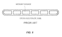
- medium passages formed in the tube are a plurality of parallel passages as illustrated in Fig. 6 .
- a medium flowing in one passage is not mixed with a medium flowing in the other passage, so that a temperature difference is generated between the passages, causing difficulty in achieving high efficiency of the heat generator.
- the present invention has been made to solve such technical problems, and an object of the present invention to achieve size reduction and high efficiency of a serpentine heat exchanger.
- a serpentine heat exchanger includes a tube formed by bonding two press-molded tube sheets and folded back in a serpentine shape, and a fin arranged in a space enclosed by the tube that is folded-back, wherein an inside of a folded-back portion of the tube includes a plurality of protrusions at a distance from one another, the protrusions protruding from one tube sheet and contacting the other tube sheet.
- the serpentine-shaped tube is formed by superposing the press-molded tube sheets and folding back the superposed tube sheets. Since a wall of the tube can be thinner than that of a tube manufactured by extrusion molding, a curvature radius of the folded portion can be reduced. This can reduce a space inside the folded portion, the space being in which the fin cannot be disposed. Thus, a larger number of the fins can be arranged, thereby achieving size reduction and high efficiency of the heat exchanger.
- a medium flowing inside the tube flows while being constantly mixed through gaps among the protrusions. This also allows the heat exchanger to achieve high efficiency.
- Fig. 1 is an overall configuration view of a serpentine heat exchanger (hereinafter called "a heat exchanger") 100 according to a first embodiment of the present invention.
- a heat exchanger a serpentine heat exchanger
- the heat exchanger 100 includes a tube 1, a corrugated fin 2, an inlet adapter 3, an outlet adapter 4, an inlet pipe 5, and an outlet pipe 6.
- the tube 1 is formed by superposing tube sheets 11 (see Fig. 4A ) and folding back the superposed tube sheets 11 in a serpentine (meandering) shape.
- Each of the tube sheets 11 includes a recessed groove 7 and a plurality of truncated conical protrusions 8 (see Fig. 2A through Fig. 2C and Fig. 3 ) formed by press molding, the truncated conical protrusions 8 protruding inside the recessed groove 7.
- a folded back portion of the tube 1 is expressed as "a folded-back portion", whereas a portion that is not folded back is expressed as "a straight portion”.
- Fig. 2A through Fig. 2C are diagrams respectively illustrating the tube 1 cut in the folded-back portion in a lateral direction, the tube 1 cut in the straight portion in a lateral direction, and the tube 1 cut in the folded-back portion and the straight portion in a longitudinal direction.
- Fig. 3 is a cross-sectional view of the tube 1.
- the protrusions 8 of one tube sheet 11 butt the protrusions 8 of the other tube sheet 11, so that pillars extending in a thickness direction of the tube 1 are formed inside the tube 1.
- the protrusions 8 are formed at a distance from one another in a surface direction (a flow direction of a medium and a direction perpendicular thereto) of the tube sheet 11.
- the protrusions 8 reinforce the straight portion, and prevent reduction in an area of passage cross-section due to a crush of the tube 1 in the folded-back portion.
- the protrusions 8 are arranged in a staggered pattern, and do not block the passage of the medium.
- the corrugated fin 2 is a fin formed by folding a metal plate in a corrugated shape.
- the corrugated fin 2 is arranged in each of the plurality of U-shaped spaces formed by the folded-back tube 1, and an upper end and a lower end thereof contact the tube 1.
- the inlet adapter 3 and the inlet pipe 5 are connected to one end of the tube 1.
- the outlet adapter 4 and the outlet pipe 6 are connected to the other end of the tube 1.
- the heat exchanger 100 is configured as described above, so that a medium flowing into the inlet adapter 3 from the inlet pipe 5 flows from a lower side to an upper side in the figure by passing inside the meandering tube 1. In the course of this process, heat of the medium is exchanged with the air passing through the corrugated fins 2. After exchanging the heat, the medium is fed to the outlet adapter 4 and discharged from the outlet pipe 6.
- the tube sheet 11 is manufactured by press working ( Fig. 4A ).
- the tube sheet 11 has the recessed groove 7 extending in a longitudinal direction in the middle thereof.
- the protrusion 8 has a height equal to a depth of the recessed groove 7.
- the tabs 12 are formed on both sides of a portion to be the folded-back portion.
- two tube sheets 11 are prepared and superposed such that the recessed grooves 7 are provided inside, thereby forming the tube 1 ( Fig. 4B ).
- the two tube sheets 11 are aligned such that positions of the protrusions 8 and the tabs 12 of one tube sheet 11 coincide with positions of the protrusions 8 and the tabs 12 of the other tube sheet 11.
- the superposition of the recessed grooves 7 forms a medium passage inside the tube 1.
- the protrusions 8 are butted together, so that the pillars extending in a thickness direction are formed inside the tube 1.
- the tabs 12 are folded, and the tube sheets 11 are swaged together ( Fig. 4C ).
- the tabs 12 are folded in the same direction as that in which the tube 1 is folded.
- the tube 1 is folded back at a plurality of locations, and thus formed in a serpentine shape ( Fig. 4D ).
- force is applied to both sides of the portion to be folded back while a jig is contacting this portion.
- the tube sheets 11 are swaged together by the tabs 12, the two tube sheets 11 can remain in close contact with each other even after the tube 1 is folded back, and a gap is not generated on a side surface of the tube 1.
- the inlet adapter 3 is connected to one end of the tube 1, and the outlet adapter 4 is connected to the other end ( Fig. 4E ).
- Each of the inlet adapter 3 and the outlet adapter 4 has a cylindrical shape, and includes an opening on an end surface thereof and a slit-shaped opening on a side surface thereof.
- the inlet pipe 5 or the outlet pipe 6 is connected to the opening, whereas the end of the tube 1 is connected to the slit-shaped opening.
- the corrugated fin 2 is inserted and arranged in a space between the folded-back tube 1 ( Fig. 4F ).
- the inlet pipe 5 is connected to the inlet adapter 3, and the outlet pipe 6 is connected to the outlet adapter 4 ( Fig. 4G ).
- the serpentine-shaped tube 1 is formed by superposing the press-molded tube sheets 11 and folding back the superposed tube sheets 11 at a plurality of locations. Since a wall of the tube 1 can be thinner than that of a tube manufactured by extrusion molding, a curvature radius of the folded portion can be reduced. This can reduce a space inside the folded portion, the space being in which the corrugated fin 2 cannot be disposed. Thus, a larger number of the corrugated fins 2 can be arranged, thereby achieving size reduction and high efficiency of the heat exchanger 100.
- a medium flowing inside the tube 1 flows while being constantly mixed through gaps among the protrusions 8 (pillars). This also enables the heat exchanger 100 to achieve high efficiency.
- the tube sheets 11 are swaged together with the tabs 12. Accordingly, when the tube 1 is folded back, the tube sheets 11 are not separated from each other, thereby preventing generation of a gap on a side surface of the tube 1.
- the protrusion 8 formed on the tube sheet 11 has a truncated conical shape, strength of the tube 1 in the straight portion can be ensured, and foldability in the folded portion can also be ensured.
- a second embodiment differs from the first embodiment in a forming method of a pillar to be formed inside a tube 1.
- the protrusions 8 are formed on both of the two tube sheets 11 forming the tube 1, and then butted together to form pillars. In the second embodiment, however, protrusions 8 are formed on only one tube sheet 11. The protrusions 8 are not formed on the other tube sheet 11. In the second embodiment, the protrusions 8 formed on one tube sheet 11 are butted on a flat surface of the other tube sheet 11, so that pillars are formed inside the tube 1.
- Fig. 5 is a cross-sectional view of the tube 1 according to the second embodiment.
- the protrusions 8 are formed on only one tube sheet 11, and not formed on the other tube sheet 11. With such a structure, pillars can be formed inside the tube 1. This structure does not require alignment of the protrusions 8, and can simplify a manufacturing process.
- the protrusions 8 are formed on the entire tube 2.
- the protrusions 8 may be provided in at least a folded portion. If strength of a straight portion can be ensured without the protrusions 8, the straight portion does not need to have the protrusions 8.
- the protrusion 8 may have a cylindrical shape or a prism shape (a triangular prism, a quadrangular prism, and the like) instead of a truncated conical shape.
Abstract
Description
- The present invention relates to a serpentine heat exchanger.
- A serpentine heat exchanger disclosed in
JP2001-27484A - The serpentine heat exchanger has a configuration in which a tube having a medium passage inside thereof is folded back in a serpentine (meandering) shape, and a fin is arranged in a space enclosed by the folded tube.
- The serpentine heat exchanger has an advantage that changes in length and folding positions/the number of folds of the tube enable various sizes, that is, various capacities, of heat exchangers to be manufactured.
- A serpentine heat exchanger needs to include fins as many as possible to achieve size reduction and high efficiency thereof by reducing a curvature radius of a folded portion of a tube by thinning a wall of the tube, and reducing a space inside the folded portion, the space being in which the fin is not arranged.
- However, since the tube used for the serpentine heat exchanger is molded by an extrusion molding, a wall of the tube has been difficult to be thinned.
- Moreover, medium passages formed in the tube are a plurality of parallel passages as illustrated in
Fig. 6 . In such a passage structure, a medium flowing in one passage is not mixed with a medium flowing in the other passage, so that a temperature difference is generated between the passages, causing difficulty in achieving high efficiency of the heat generator. - The present invention has been made to solve such technical problems, and an object of the present invention to achieve size reduction and high efficiency of a serpentine heat exchanger.
- According to one aspect of the present invention, a serpentine heat exchanger includes a tube formed by bonding two press-molded tube sheets and folded back in a serpentine shape, and a fin arranged in a space enclosed by the tube that is folded-back, wherein an inside of a folded-back portion of the tube includes a plurality of protrusions at a distance from one another, the protrusions protruding from one tube sheet and contacting the other tube sheet.
- According to the above aspect, the serpentine-shaped tube is formed by superposing the press-molded tube sheets and folding back the superposed tube sheets. Since a wall of the tube can be thinner than that of a tube manufactured by extrusion molding, a curvature radius of the folded portion can be reduced. This can reduce a space inside the folded portion, the space being in which the fin cannot be disposed. Thus, a larger number of the fins can be arranged, thereby achieving size reduction and high efficiency of the heat exchanger.
- Moreover, a medium flowing inside the tube flows while being constantly mixed through gaps among the protrusions. This also allows the heat exchanger to achieve high efficiency.
-
- [
Fig. 1] Fig. 1 is an overall configuration view of a serpentine heat exchanger according to a first embodiment of the present invention. - [
Fig. 2A] Fig. 2A is a diagram illustrating a tube which is cut in a folded-back portion in a lateral direction. - [
Fig. 2B] Fig. 2B is a diagram illustrating a tube which is cut in a straight portion in a lateral direction. - [
Fig. 2C] Fig. 2C is a diagram illustrating a tube which is cut in a folded-back portion and a straight portion in a longitudinal direction. - [
Fig. 3] Fig. 3 is a cross-sectional view of a tube. - [
Fig. 4A] Fig. 4A is a diagram explaining a manufacturing method. - [
Fig. 4B] Fig. 4B is a diagram explaining the manufacturing method. - [
Fig. 4C] Fig. 4C is a diagram explaining the manufacturing method. - [
Fig. 4D] Fig. 4D is a diagram explaining the manufacturing method. - [
Fig. 4E] Fig. 4E is a diagram explaining the manufacturing method. - [
Fig. 4F] Fig. 4F is a diagram explaining the manufacturing method. - [
Fig. 4G] Fig. 4G is a diagram explaining the manufacturing method. - [
Fig. 4H] Fig. 4H is a diagram explaining the manufacturing method. - [
Fig. 5] Fig. 5 is a cross-sectional view of a tube according to a second embodiment of the present invention. - [
Fig. 6] Fig. 6 is a cross-sectional view of a conventional tube. - Hereinafter, embodiments of the present invention will be described with reference to the drawings.
-
Fig. 1 is an overall configuration view of a serpentine heat exchanger (hereinafter called "a heat exchanger") 100 according to a first embodiment of the present invention. - The
heat exchanger 100 includes atube 1, acorrugated fin 2, aninlet adapter 3, anoutlet adapter 4, aninlet pipe 5, and anoutlet pipe 6. - The
tube 1 is formed by superposing tube sheets 11 (seeFig. 4A ) and folding back thesuperposed tube sheets 11 in a serpentine (meandering) shape. Each of thetube sheets 11 includes arecessed groove 7 and a plurality of truncated conical protrusions 8 (seeFig. 2A through Fig. 2C andFig. 3 ) formed by press molding, the truncatedconical protrusions 8 protruding inside the recessedgroove 7. In the description below, a folded back portion of thetube 1 is expressed as "a folded-back portion", whereas a portion that is not folded back is expressed as "a straight portion". -
Fig. 2A through Fig. 2C are diagrams respectively illustrating thetube 1 cut in the folded-back portion in a lateral direction, thetube 1 cut in the straight portion in a lateral direction, and thetube 1 cut in the folded-back portion and the straight portion in a longitudinal direction.Fig. 3 is a cross-sectional view of thetube 1. - As illustrated in these diagrams, the
protrusions 8 of onetube sheet 11 butt theprotrusions 8 of theother tube sheet 11, so that pillars extending in a thickness direction of thetube 1 are formed inside thetube 1. Theprotrusions 8 are formed at a distance from one another in a surface direction (a flow direction of a medium and a direction perpendicular thereto) of thetube sheet 11. Theprotrusions 8 reinforce the straight portion, and prevent reduction in an area of passage cross-section due to a crush of thetube 1 in the folded-back portion. Theprotrusions 8 are arranged in a staggered pattern, and do not block the passage of the medium. - In the folded-back portion of the
tube 1,tabs 12 of thetube sheets 11 are folded in a folding back direction of thetube 1, so that thetube sheets 11 are swaged together. - The
corrugated fin 2 is a fin formed by folding a metal plate in a corrugated shape. Thecorrugated fin 2 is arranged in each of the plurality of U-shaped spaces formed by the folded-back tube 1, and an upper end and a lower end thereof contact thetube 1. - The
inlet adapter 3 and theinlet pipe 5 are connected to one end of thetube 1. Theoutlet adapter 4 and theoutlet pipe 6 are connected to the other end of thetube 1. - The
heat exchanger 100 according to the first embodiment is configured as described above, so that a medium flowing into theinlet adapter 3 from theinlet pipe 5 flows from a lower side to an upper side in the figure by passing inside the meanderingtube 1. In the course of this process, heat of the medium is exchanged with the air passing through thecorrugated fins 2. After exchanging the heat, the medium is fed to theoutlet adapter 4 and discharged from theoutlet pipe 6. - Next, a manufacturing method of the
heat exchanger 100 according to the first embodiment is described with reference toFig. 4A through Fig. 4H . - First, the
tube sheet 11 is manufactured by press working (Fig. 4A ). Thetube sheet 11 has the recessedgroove 7 extending in a longitudinal direction in the middle thereof. The plurality ofprotrusions 8, at a distance from one another in a surface direction of thetube sheet 11, protrudes from a bottom of the recessedgroove 7. Theprotrusion 8 has a height equal to a depth of the recessedgroove 7. Moreover, thetabs 12 are formed on both sides of a portion to be the folded-back portion. - Next, two
tube sheets 11 are prepared and superposed such that the recessedgrooves 7 are provided inside, thereby forming the tube 1 (Fig. 4B ). Herein, the twotube sheets 11 are aligned such that positions of theprotrusions 8 and thetabs 12 of onetube sheet 11 coincide with positions of theprotrusions 8 and thetabs 12 of theother tube sheet 11. The superposition of the recessedgrooves 7 forms a medium passage inside thetube 1. Moreover, theprotrusions 8 are butted together, so that the pillars extending in a thickness direction are formed inside thetube 1. - Subsequently, the
tabs 12 are folded, and thetube sheets 11 are swaged together (Fig. 4C ). Thetabs 12 are folded in the same direction as that in which thetube 1 is folded. - Next, the
tube 1 is folded back at a plurality of locations, and thus formed in a serpentine shape (Fig. 4D ). When thetube 1 is fold back, force is applied to both sides of the portion to be folded back while a jig is contacting this portion. In this portion, since thetube sheets 11 are swaged together by thetabs 12, the twotube sheets 11 can remain in close contact with each other even after thetube 1 is folded back, and a gap is not generated on a side surface of thetube 1. - Next, the
inlet adapter 3 is connected to one end of thetube 1, and theoutlet adapter 4 is connected to the other end (Fig. 4E ). Each of theinlet adapter 3 and theoutlet adapter 4 has a cylindrical shape, and includes an opening on an end surface thereof and a slit-shaped opening on a side surface thereof. Theinlet pipe 5 or theoutlet pipe 6 is connected to the opening, whereas the end of thetube 1 is connected to the slit-shaped opening. - Subsequently, the
corrugated fin 2 is inserted and arranged in a space between the folded-back tube 1 (Fig. 4F ). - Next, the
inlet pipe 5 is connected to theinlet adapter 3, and theoutlet pipe 6 is connected to the outlet adapter 4 (Fig. 4G ). - Lastly, the entire heat exchanger is placed in a furnace, and each of the components is bonded by blazing (
Fig. 4H ). - Now, an operational effect of the first embodiment is described.
- According to the first embodiment, the serpentine-shaped
tube 1 is formed by superposing the press-moldedtube sheets 11 and folding back the superposedtube sheets 11 at a plurality of locations. Since a wall of thetube 1 can be thinner than that of a tube manufactured by extrusion molding, a curvature radius of the folded portion can be reduced. This can reduce a space inside the folded portion, the space being in which thecorrugated fin 2 cannot be disposed. Thus, a larger number of thecorrugated fins 2 can be arranged, thereby achieving size reduction and high efficiency of theheat exchanger 100. - Moreover, in a case where a wall thickness of the
tube 1 is reduced, there is a possibility that thetube 1 may be crushed in a folded portion. In the first embodiment, however, since pillars are formed inside thetube 1 by theprotrusions 8 protruding from thetube sheet 11, a reduction in a passage cross-sectional area due to a crush of thetube 1 in the folded portion does not occur. - In addition, a medium flowing inside the
tube 1 flows while being constantly mixed through gaps among the protrusions 8 (pillars). This also enables theheat exchanger 100 to achieve high efficiency. - Moreover, in the folded-back portion, the
tube sheets 11 are swaged together with thetabs 12. Accordingly, when thetube 1 is folded back, thetube sheets 11 are not separated from each other, thereby preventing generation of a gap on a side surface of thetube 1. - Moreover, since the
protrusion 8 formed on thetube sheet 11 has a truncated conical shape, strength of thetube 1 in the straight portion can be ensured, and foldability in the folded portion can also be ensured. - A second embodiment differs from the first embodiment in a forming method of a pillar to be formed inside a
tube 1. - In the first embodiment, the
protrusions 8 are formed on both of the twotube sheets 11 forming thetube 1, and then butted together to form pillars. In the second embodiment, however,protrusions 8 are formed on only onetube sheet 11. Theprotrusions 8 are not formed on theother tube sheet 11. In the second embodiment, theprotrusions 8 formed on onetube sheet 11 are butted on a flat surface of theother tube sheet 11, so that pillars are formed inside thetube 1. -
Fig. 5 is a cross-sectional view of thetube 1 according to the second embodiment. Theprotrusions 8 are formed on only onetube sheet 11, and not formed on theother tube sheet 11. With such a structure, pillars can be formed inside thetube 1. This structure does not require alignment of theprotrusions 8, and can simplify a manufacturing process. - Since other configurations are the same as the first embodiment, the descriptions thereof are omitted.
- While the embodiments of the present invention have been described, it is to be understood that the above embodiments are examples of application of the present invention, and a technical scope of the present invention is not limited to the particular configurations of the above embodiments.
- For example, in the above embodiments, the
protrusions 8 are formed on theentire tube 2. However, theprotrusions 8 may be provided in at least a folded portion. If strength of a straight portion can be ensured without theprotrusions 8, the straight portion does not need to have theprotrusions 8. - Moreover, the
protrusion 8 may have a cylindrical shape or a prism shape (a triangular prism, a quadrangular prism, and the like) instead of a truncated conical shape. - This application claims priority from Japanese Patent Application No.
2011-135178
Claims (7)
- A serpentine heat exchanger comprising:a tube formed by bonding two press-molded tube sheets and folded back in a serpentine shape; anda fin arranged in a space enclosed by the tube that is folded-back, whereinan inside of a folded-back portion of the tube includes a plurality of protrusions at a distance from one another, the protrusions protruding from a first tube sheet and contacting a second tube sheet.
- The serpentine heat exchanger according to claim 1, wherein
an inside of a straight portion of the tube also includes the protrusions. - The serpentine heat exchanger according to claim 1, wherein
the protrusion is butted on another protrusion protruding from the second tube sheet. - The serpentine heat exchanger according to claim 1, wherein
the protrusions are formed only on the first tube sheet. - The serpentine heat exchanger according to claim 1, wherein
the protrusions are arranged in a staggered pattern. - The serpentine heat exchanger according to claim 1, wherein
the protrusion has a truncated conical shape, a cylindrical shape, or a prism shape. - The serpentine heat exchanger according to claim 1, wherein
the first tube sheet and the second tube sheet are swaged together on both sides in the folded-back portion of the tube.
Applications Claiming Priority (2)
| Application Number | Priority Date | Filing Date | Title |
|---|---|---|---|
| JP2011135178A JP5663413B2 (en) | 2011-06-17 | 2011-06-17 | Serpentine heat exchanger |
| PCT/JP2012/062900 WO2012172928A1 (en) | 2011-06-17 | 2012-05-21 | Serpentine heat exchanger |
Publications (2)
| Publication Number | Publication Date |
|---|---|
| EP2722628A1 true EP2722628A1 (en) | 2014-04-23 |
| EP2722628A4 EP2722628A4 (en) | 2015-06-03 |
Family
ID=47356922
Family Applications (1)
| Application Number | Title | Priority Date | Filing Date |
|---|---|---|---|
| EP12800204.5A Withdrawn EP2722628A4 (en) | 2011-06-17 | 2012-05-21 | Serpentine heat exchanger |
Country Status (5)
| Country | Link |
|---|---|
| US (1) | US20140116662A1 (en) |
| EP (1) | EP2722628A4 (en) |
| JP (1) | JP5663413B2 (en) |
| CN (1) | CN103608636A (en) |
| WO (1) | WO2012172928A1 (en) |
Families Citing this family (8)
| Publication number | Priority date | Publication date | Assignee | Title |
|---|---|---|---|---|
| DE102012011520A1 (en) * | 2012-06-08 | 2013-12-12 | Fraunhofer-Gesellschaft zur Förderung der angewandten Forschung e.V. | Heat exchanger system, method of making same and fluid distribution element |
| USD763417S1 (en) * | 2012-08-02 | 2016-08-09 | Mitsubishi Electric Corporation | Heat exchanger tube |
| AU2013401471B2 (en) * | 2013-09-30 | 2017-09-21 | Arcelik Anonim Sirketi | Forced convection heat exchanger for a refrigeration appliance |
| CN104061683A (en) * | 2014-06-14 | 2014-09-24 | 广东万和新电气股份有限公司 | Cast aluminum heat exchanger of gas-fired boiler |
| FR3040478B1 (en) * | 2015-08-25 | 2017-12-15 | Valeo Systemes Thermiques | HEAT EXCHANGER |
| CN105352181A (en) * | 2015-11-13 | 2016-02-24 | 任能 | Improved condensation type gas warm bath dual-purpose heat exchanger |
| US20170336152A1 (en) * | 2016-05-20 | 2017-11-23 | Hyundai Motor Company | Double-sided cooler for cooling both sides of electronic component |
| DE102017222742A1 (en) * | 2017-12-14 | 2019-06-19 | Hanon Systems | Pipe, in particular flat pipe for an exhaust gas cooler and exhaust gas cooler |
Family Cites Families (14)
| Publication number | Priority date | Publication date | Assignee | Title |
|---|---|---|---|---|
| JPS5254062Y2 (en) * | 1972-07-06 | 1977-12-07 | ||
| JPS4950857U (en) * | 1972-08-07 | 1974-05-04 | ||
| JPS4950857A (en) * | 1972-09-18 | 1974-05-17 | ||
| JPS5730582U (en) * | 1980-07-30 | 1982-02-17 | ||
| DE3142028A1 (en) * | 1981-10-23 | 1983-05-05 | Süddeutsche Kühlerfabrik Julius Fr. Behr GmbH & Co KG, 7000 Stuttgart | OIL COOLER |
| JPS5959688U (en) * | 1982-10-12 | 1984-04-18 | 株式会社デンソー | Heat exchanger |
| JPS5970180U (en) * | 1982-11-01 | 1984-05-12 | 昭和アルミニウム株式会社 | Evaporator |
| JPH0566073A (en) * | 1991-09-05 | 1993-03-19 | Sanden Corp | Multilayered heat exchanger |
| JPH07227631A (en) * | 1993-12-21 | 1995-08-29 | Zexel Corp | Guide tube for heat exchanging in laminated layer type heat exchanger and its manufacture |
| JP2001027484A (en) | 1999-07-15 | 2001-01-30 | Zexel Valeo Climate Control Corp | Serpentine heat-exchanger |
| JP2001248988A (en) * | 2000-03-06 | 2001-09-14 | Mitsubishi Heavy Ind Ltd | Heat exchanger |
| CN100340835C (en) * | 2001-12-17 | 2007-10-03 | 昭和电工株式会社 | Heat exchanger and process for fabricating same |
| EP1541953B1 (en) * | 2002-07-09 | 2007-04-25 | Zexel Valeo Climate Control Corporation | Tube for heat exchanger |
| US20040099408A1 (en) * | 2002-11-26 | 2004-05-27 | Shabtay Yoram Leon | Interconnected microchannel tube |
-
2011
- 2011-06-17 JP JP2011135178A patent/JP5663413B2/en not_active Expired - Fee Related
-
2012
- 2012-05-21 CN CN201280029492.6A patent/CN103608636A/en active Pending
- 2012-05-21 WO PCT/JP2012/062900 patent/WO2012172928A1/en active Application Filing
- 2012-05-21 US US14/124,345 patent/US20140116662A1/en not_active Abandoned
- 2012-05-21 EP EP12800204.5A patent/EP2722628A4/en not_active Withdrawn
Also Published As
| Publication number | Publication date |
|---|---|
| JP5663413B2 (en) | 2015-02-04 |
| JP2013002753A (en) | 2013-01-07 |
| WO2012172928A1 (en) | 2012-12-20 |
| CN103608636A (en) | 2014-02-26 |
| EP2722628A4 (en) | 2015-06-03 |
| US20140116662A1 (en) | 2014-05-01 |
Similar Documents
| Publication | Publication Date | Title |
|---|---|---|
| EP2722628A1 (en) | Serpentine heat exchanger | |
| EP2884209B1 (en) | Bent heat exchanger and method for bending the heat exchanger | |
| JP4171760B2 (en) | Flat tube and manufacturing method of flat tube | |
| US20140196877A1 (en) | Tube for heat exchanger | |
| EP1521050A2 (en) | Tube for heat exchanger | |
| EP3355020A1 (en) | Heat exchange tube for heat exchanger, heat exchanger and assembly method thereof | |
| EP3141860A1 (en) | Plate heat exchanger and method for producing same | |
| US10989485B2 (en) | Heat exchanger tube, and corresponding heat exchanger production method | |
| US5603159A (en) | Method of producing heat exchangers | |
| US6438840B2 (en) | Method of making continuous corrugated heat exchanger | |
| EP3578913B1 (en) | Heat exchanger and refrigeration cycle apparatus | |
| JP4448354B2 (en) | Heat exchanger | |
| WO2008047827A1 (en) | Heat exchanger tube and method of producing the same | |
| WO2006129598A1 (en) | Heat exchanger | |
| JP2007147173A (en) | Heat exchanger and its manufacturing method | |
| WO2015081274A1 (en) | Flattened envelope heat exchanger | |
| JP5140803B2 (en) | Heat exchanger and manufacturing method thereof | |
| JP2015113983A (en) | Heat exchanger | |
| CN112368537B (en) | Heat transport device and method for manufacturing the same | |
| EP4151942A1 (en) | Flat tube | |
| JP4312640B2 (en) | Stacked heat exchanger | |
| JP2004347159A (en) | Heat exchanger | |
| JP6207989B2 (en) | Heat exchanger | |
| JPS6314083A (en) | Laminated type heat exchanger | |
| EP3598047B1 (en) | Heat exchanger tube |
Legal Events
| Date | Code | Title | Description |
|---|---|---|---|
| PUAI | Public reference made under article 153(3) epc to a published international application that has entered the european phase |
Free format text: ORIGINAL CODE: 0009012 |
|
| 17P | Request for examination filed |
Effective date: 20140115 |
|
| AK | Designated contracting states |
Kind code of ref document: A1 Designated state(s): AL AT BE BG CH CY CZ DE DK EE ES FI FR GB GR HR HU IE IS IT LI LT LU LV MC MK MT NL NO PL PT RO RS SE SI SK SM TR |
|
| DAX | Request for extension of the european patent (deleted) | ||
| RA4 | Supplementary search report drawn up and despatched (corrected) |
Effective date: 20150506 |
|
| RIC1 | Information provided on ipc code assigned before grant |
Ipc: F28F 3/04 20060101ALN20150428BHEP Ipc: F28D 1/03 20060101ALN20150428BHEP Ipc: F28F 1/12 20060101ALI20150428BHEP Ipc: F28F 1/40 20060101ALI20150428BHEP Ipc: F28F 1/42 20060101ALI20150428BHEP Ipc: F28D 1/047 20060101AFI20150428BHEP |
|
| STAA | Information on the status of an ep patent application or granted ep patent |
Free format text: STATUS: THE APPLICATION HAS BEEN WITHDRAWN |
|
| 18W | Application withdrawn |
Effective date: 20151120 |