EP3508790B1 - Gasturbinenmotor mit einem modulierten brennkammer-bypass und einem brennkammer-bypassventil - Google Patents
Gasturbinenmotor mit einem modulierten brennkammer-bypass und einem brennkammer-bypassventil Download PDFInfo
- Publication number
- EP3508790B1 EP3508790B1 EP19150786.2A EP19150786A EP3508790B1 EP 3508790 B1 EP3508790 B1 EP 3508790B1 EP 19150786 A EP19150786 A EP 19150786A EP 3508790 B1 EP3508790 B1 EP 3508790B1
- Authority
- EP
- European Patent Office
- Prior art keywords
- combustor
- gas turbine
- bypass
- valve
- engine
- Prior art date
- Legal status (The legal status is an assumption and is not a legal conclusion. Google has not performed a legal analysis and makes no representation as to the accuracy of the status listed.)
- Active
Links
- 238000011144 upstream manufacturing Methods 0.000 claims description 11
- 238000002485 combustion reaction Methods 0.000 claims description 4
- 238000000034 method Methods 0.000 claims description 4
- 230000004044 response Effects 0.000 claims description 3
- 239000000446 fuel Substances 0.000 description 5
- 230000008859 change Effects 0.000 description 4
- 230000003068 static effect Effects 0.000 description 3
- 230000009467 reduction Effects 0.000 description 2
- 238000004891 communication Methods 0.000 description 1
- 230000006835 compression Effects 0.000 description 1
- 238000007906 compression Methods 0.000 description 1
- 238000001816 cooling Methods 0.000 description 1
- 230000003247 decreasing effect Effects 0.000 description 1
- 230000001627 detrimental effect Effects 0.000 description 1
- 230000000694 effects Effects 0.000 description 1
- 238000005259 measurement Methods 0.000 description 1
- 230000007246 mechanism Effects 0.000 description 1
- 230000001105 regulatory effect Effects 0.000 description 1
Images


Classifications
-
- F—MECHANICAL ENGINEERING; LIGHTING; HEATING; WEAPONS; BLASTING
- F02—COMBUSTION ENGINES; HOT-GAS OR COMBUSTION-PRODUCT ENGINE PLANTS
- F02C—GAS-TURBINE PLANTS; AIR INTAKES FOR JET-PROPULSION PLANTS; CONTROLLING FUEL SUPPLY IN AIR-BREATHING JET-PROPULSION PLANTS
- F02C9/00—Controlling gas-turbine plants; Controlling fuel supply in air- breathing jet-propulsion plants
- F02C9/16—Control of working fluid flow
- F02C9/18—Control of working fluid flow by bleeding, bypassing or acting on variable working fluid interconnections between turbines or compressors or their stages
-
- F—MECHANICAL ENGINEERING; LIGHTING; HEATING; WEAPONS; BLASTING
- F01—MACHINES OR ENGINES IN GENERAL; ENGINE PLANTS IN GENERAL; STEAM ENGINES
- F01D—NON-POSITIVE DISPLACEMENT MACHINES OR ENGINES, e.g. STEAM TURBINES
- F01D17/00—Regulating or controlling by varying flow
- F01D17/10—Final actuators
- F01D17/12—Final actuators arranged in stator parts
- F01D17/14—Final actuators arranged in stator parts varying effective cross-sectional area of nozzles or guide conduits
- F01D17/141—Final actuators arranged in stator parts varying effective cross-sectional area of nozzles or guide conduits by means of shiftable members or valves obturating part of the flow path
- F01D17/145—Final actuators arranged in stator parts varying effective cross-sectional area of nozzles or guide conduits by means of shiftable members or valves obturating part of the flow path by means of valves, e.g. for steam turbines
-
- F—MECHANICAL ENGINEERING; LIGHTING; HEATING; WEAPONS; BLASTING
- F01—MACHINES OR ENGINES IN GENERAL; ENGINE PLANTS IN GENERAL; STEAM ENGINES
- F01D—NON-POSITIVE DISPLACEMENT MACHINES OR ENGINES, e.g. STEAM TURBINES
- F01D17/00—Regulating or controlling by varying flow
- F01D17/10—Final actuators
- F01D17/12—Final actuators arranged in stator parts
- F01D17/14—Final actuators arranged in stator parts varying effective cross-sectional area of nozzles or guide conduits
- F01D17/16—Final actuators arranged in stator parts varying effective cross-sectional area of nozzles or guide conduits by means of nozzle vanes
- F01D17/162—Final actuators arranged in stator parts varying effective cross-sectional area of nozzles or guide conduits by means of nozzle vanes for axial flow, i.e. the vanes turning around axes which are essentially perpendicular to the rotor centre line
-
- F—MECHANICAL ENGINEERING; LIGHTING; HEATING; WEAPONS; BLASTING
- F02—COMBUSTION ENGINES; HOT-GAS OR COMBUSTION-PRODUCT ENGINE PLANTS
- F02C—GAS-TURBINE PLANTS; AIR INTAKES FOR JET-PROPULSION PLANTS; CONTROLLING FUEL SUPPLY IN AIR-BREATHING JET-PROPULSION PLANTS
- F02C9/00—Controlling gas-turbine plants; Controlling fuel supply in air- breathing jet-propulsion plants
- F02C9/16—Control of working fluid flow
- F02C9/20—Control of working fluid flow by throttling; by adjusting vanes
- F02C9/22—Control of working fluid flow by throttling; by adjusting vanes by adjusting turbine vanes
-
- F—MECHANICAL ENGINEERING; LIGHTING; HEATING; WEAPONS; BLASTING
- F23—COMBUSTION APPARATUS; COMBUSTION PROCESSES
- F23R—GENERATING COMBUSTION PRODUCTS OF HIGH PRESSURE OR HIGH VELOCITY, e.g. GAS-TURBINE COMBUSTION CHAMBERS
- F23R3/00—Continuous combustion chambers using liquid or gaseous fuel
- F23R3/02—Continuous combustion chambers using liquid or gaseous fuel characterised by the air-flow or gas-flow configuration
- F23R3/26—Controlling the air flow
-
- F—MECHANICAL ENGINEERING; LIGHTING; HEATING; WEAPONS; BLASTING
- F02—COMBUSTION ENGINES; HOT-GAS OR COMBUSTION-PRODUCT ENGINE PLANTS
- F02C—GAS-TURBINE PLANTS; AIR INTAKES FOR JET-PROPULSION PLANTS; CONTROLLING FUEL SUPPLY IN AIR-BREATHING JET-PROPULSION PLANTS
- F02C6/00—Plural gas-turbine plants; Combinations of gas-turbine plants with other apparatus; Adaptations of gas- turbine plants for special use
- F02C6/04—Gas-turbine plants providing heated or pressurised working fluid for other apparatus, e.g. without mechanical power output
- F02C6/06—Gas-turbine plants providing heated or pressurised working fluid for other apparatus, e.g. without mechanical power output providing compressed gas
- F02C6/08—Gas-turbine plants providing heated or pressurised working fluid for other apparatus, e.g. without mechanical power output providing compressed gas the gas being bled from the gas-turbine compressor
-
- F—MECHANICAL ENGINEERING; LIGHTING; HEATING; WEAPONS; BLASTING
- F02—COMBUSTION ENGINES; HOT-GAS OR COMBUSTION-PRODUCT ENGINE PLANTS
- F02C—GAS-TURBINE PLANTS; AIR INTAKES FOR JET-PROPULSION PLANTS; CONTROLLING FUEL SUPPLY IN AIR-BREATHING JET-PROPULSION PLANTS
- F02C9/00—Controlling gas-turbine plants; Controlling fuel supply in air- breathing jet-propulsion plants
- F02C9/48—Control of fuel supply conjointly with another control of the plant
- F02C9/50—Control of fuel supply conjointly with another control of the plant with control of working fluid flow
- F02C9/54—Control of fuel supply conjointly with another control of the plant with control of working fluid flow by throttling the working fluid, by adjusting vanes
-
- F—MECHANICAL ENGINEERING; LIGHTING; HEATING; WEAPONS; BLASTING
- F05—INDEXING SCHEMES RELATING TO ENGINES OR PUMPS IN VARIOUS SUBCLASSES OF CLASSES F01-F04
- F05D—INDEXING SCHEME FOR ASPECTS RELATING TO NON-POSITIVE-DISPLACEMENT MACHINES OR ENGINES, GAS-TURBINES OR JET-PROPULSION PLANTS
- F05D2240/00—Components
- F05D2240/35—Combustors or associated equipment
Definitions
- Exemplary embodiments pertain to the art of gas turbine engines, and more particularly to combustor and turbine operation of gas turbine engines.
- Some gas turbine engines are configured a variable-area turbine (VAT), in which the turbine flow area is changeable during operation of the gas turbine engine.
- VAT variable-area turbine
- the turbine flow area is changed by adjusting positions of the turbine vanes.
- the change in turbine flow area changes the fuel air factor (FAF) of the combustor upstream of the turbine, however, which may have detrimental effects on the operation and efficiency of the combustor.
- FAF fuel air factor
- GB 25 30629 discloses a gas turbine engine comprising a combustor bypass passage, wherein the combustor bypass passage includes a control valve.
- a gas turbine engine includes a gas turbine engine central longitudinal axis and a combustor section which comprises a combustor having a combustor inlet and a combustor bypass passage having a passage inlet located upstream of the combustor inlet, the combustor bypass passage configured to divert a selected bypass airflow around the combustor.
- a combustor bypass valve is located at the combustor bypass passage to control the selected bypass airflow along the combustor bypass passage.
- the combustor bypass valve including a valve element extending circumferentially about the engine central longitudinal axis and configured to rotate about said engine central longitudinal axis to move one or more valve openings relative to one or more bypass passage openings.
- the one or more valve openings may comprise a plurality of valve openings.
- the passage inlet may be a bypass inlet.
- the bypass passage openings may be bypass inlet openings.
- valve element is a tubular sleeve, with the one or more valve openings located in the sleeve.
- the tubular sleeve may be a full ring.
- the valve element may be a full ring.
- the valve element may include the one or more openings.
- valve element is driven about the engine central longitudinal axis by one or more actuators.
- the combustor inlet is configured to be in an aerodynamically choked state when a flowpath area of a variable area turbine located downstream of the combustor is at a minimum area.
- the combustor bypass valve is located upstream of a combustor inlet choke location.
- the combustor bypass valve is configured to move from a closed position toward a fully open position as the flowpath area of the variable area turbine is increased.
- the combustor bypass passage includes a passage outlet located at a turbine section of the gas turbine engine.
- the combustor bypass valve is located at the passage inlet.
- the gas turbine engine includes a variable area turbine, configured such that a flowpath area of the variable area turbine is selectably changeable, a combustor located upstream of the variable area turbine and having a combustor inlet, and a combustor bypass passage having a passage inlet located upstream of the combustor inlet and downstream of a compressor section of the gas turbine engine.
- the combustor bypass passage is configured to divert a selected bypass airflow around the combustor.
- a combustor bypass valve is located at the combustor bypass passage to control the selected bypass airflow along the combustor bypass passage.
- the combustor bypass valve includes a valve element extending circumferentially about an engine control longitudinal axis and configured to rotate about the engine central longitudinal axis to move one or more valve openings relative to one or more bypass passage openings.
- valve element is a tubular sleeve, with the one or more valve openings located in the sleeve.
- valve element is driven about the engine central longitudinal axis by one or more actuators.
- the combustor inlet is configured to be in an aerodynamically choked state when the flowpath area of the variable area turbine is at a minimum area.
- the combustor bypass valve is located upstream of a combustor inlet choke location.
- the combustor bypass valve is configured to move from a closed position toward a fully open position as the flowpath area of the variable area turbine is increased.
- variable area turbine includes one or more turbine vanes, the one or more turbine vanes configured to be movable, thereby changing the flowpath area.
- the one or more turbine vanes are movable about a vane axis.
- the combustor bypass passage includes a passage outlet located at the variable area turbine.
- the combustor bypass valve is located at the passage inlet.
- a method of operating the gas turbine engine of previous embodiments includes adjusting an area of a turbine section of the gas turbine, and bypassing, in response to said adjusting step, a portion of core airflow entering a combustor section around a combustion chamber.
- the combustion chamber may be termed a "combustor”.
- bypassing the portion of core airflow includes rotating a valve element about an engine central longitudinal axis to move one or more valve openings relative to one or more bypass passage openings, and flowing the portion of core airflow through the one or more bypass passage openings via the one or more valve openings.
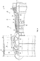
- FIG. 1 schematically illustrates a gas turbine engine 20.
- the gas turbine engine 20 is disclosed herein as a two-spool turbofan that generally incorporates a fan section 22, a compressor section 24, a combustor section 26 and a turbine section 28.
- Alternative engines might include an augmentor section (not shown) among other systems or features.
- the fan section 22 drives air along a bypass flow path B in a bypass duct, while the compressor section 24 drives air along a core flow path C for compression and communication into the combustor section 26 then expansion through the turbine section 28.
- the exemplary engine 20 generally includes a low speed spool 30 and a high speed spool 32 mounted for rotation about an engine central longitudinal axis A relative to an engine static structure 36 via several bearing systems 38. It should be understood that various bearing systems 38 at various locations may alternatively or additionally be provided, and the location of bearing systems 38 may be varied as appropriate to the application.
- the low speed spool 30 generally includes an inner shaft 40 that interconnects a fan 42, a low pressure compressor 44 and a low pressure turbine 46.
- the inner shaft 40 is connected to the fan 42 through a speed change mechanism, which in exemplary gas turbine engine 20 is illustrated as a geared architecture 48 to drive the fan 42 at a lower speed than the low speed spool 30.
- the high speed spool 32 includes an outer shaft 50 that interconnects a high pressure compressor 52 and high pressure turbine 54.
- a combustor 56 is arranged in exemplary gas turbine 20 between the high pressure compressor 52 and the high pressure turbine 54.
- An engine static structure 36 is arranged generally between the high pressure turbine 54 and the low pressure turbine 46.
- the engine static structure 36 further supports bearing systems 38 in the turbine section 28.
- the inner shaft 40 and the outer shaft 50 are concentric and rotate via bearing systems 38 about the engine central longitudinal axis A which is collinear with their longitudinal axes.
- each of the positions of the fan section 22, compressor section 24, combustor section 26, turbine section 28, and fan drive gear system 48 may be varied.
- gear system 48 may be located aft of combustor section 26 or even aft of turbine section 28, and fan section 22 may be positioned forward or aft of the location of gear system 48.
- the engine 20 in one example is a high-bypass geared aircraft engine.
- the engine 20 bypass ratio is greater than about six (6), with an example embodiment being greater than about ten (10)
- the geared architecture 48 is an epicyclic gear train, such as a planetary gear system or other gear system, with a gear reduction ratio of greater than about 2.3 and the low pressure turbine 46 has a pressure ratio that is greater than about five.
- the engine 20 bypass ratio is greater than about ten (10:1)
- the fan diameter is significantly larger than that of the low pressure compressor 44
- the low pressure turbine 46 has a pressure ratio that is greater than about five (5:1).
- Low pressure turbine 46 pressure ratio is pressure measured prior to inlet of low pressure turbine 46 as related to the pressure at the outlet of the low pressure turbine 46 prior to an exhaust nozzle.
- the geared architecture 48 may be an epicycle gear train, such as a planetary gear system or other gear system, with a gear reduction ratio of greater than about 2.3:1. It should be understood, however, that the above parameters are only exemplary of one embodiment of a geared architecture engine and that the present disclosure is applicable to other gas turbine engines including direct drive turbofans.
- the fan section 22 of the engine 20 is designed for a particular flight condition--typically cruise at about 0.8 Mach and about 35,000 feet (10,668 meters).
- 'TSFC' Thrust Specific Fuel Consumption
- Low fan pressure ratio is the pressure ratio across the fan blade alone, without a Fan Exit Guide Vane (“FEGV”) system.
- the low fan pressure ratio as disclosed herein according to one non-limiting embodiment is less than about 1.45.
- Low corrected fan tip speed is the actual fan tip speed in ft/sec divided by an industry standard temperature correction of [(Tram °R)/(518.7 °R)]0.5.
- the "Low corrected fan tip speed” as disclosed herein according to one non-limiting embodiment is less than about 1150 ft/second (350.5 m/sec).
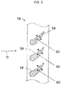
- the turbine section 28 for example, the high pressure turbine 54 is configured as a variable-area turbine (VAT), such that flow area of combustion products from the combustor 56 along a flowpath D is changeable.
- VAT variable-area turbine
- the flow area is changed using variable turbine vanes 58 that rotate about a vane axis 60. It is to be appreciated that in other embodiments the flow area may be changed in other ways including changing the position of the turbine vanes 58 by sliding rather than rotating, or by moving other flowpath structure relative to the turbine vanes 58 to change the area of flowpath D.
- the stator vanes 58 direct the core flow to turbine rotor blades 88.
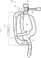
- the combustor 56 includes a combustor inlet 62 to receive airflow from the high pressure compressor 24 along the core flowpath C, and to direct the airflow into the combustor 56.
- the combustor inlet 62 is configured with an inlet cross-sectional area in which the airflow through the combustor inlet 62 is aerodynamically choked, or at a maximum flow velocity, when the turbine vanes 58 are positioned such that the area of flowpath D is at its minimum.
- a combustor bypass passage 64 is positioned with a bypass inlet 66 along flowpath C upstream of the combustor inlet 62, and includes a bypass outlet 68 at the turbine section 28. Further, the bypass inlet 66 is located downstream of the compressor section 24.
- the bypass passage 64 is configured to direct a bypass airflow 70 around the combustor 56 from core flowpath C upstream of the combustor 56 and reintroduce the bypass airflow into the flowpath D at the turbine section 28, for example, at the high pressure turbine 54 at the variable turbine blades 58, or alternatively downstream of the variable turbine blades 58. While the bypass passage 64 shown in FIG.
- bypass passage 64 may be in another location, such as radially inboard of the combustor 56, as shown in figure 4 .
- a combustor bypass valve 72 is located along the main gaspath 24, for example, at the bypass inlet 66 such as in the embodiment illustrated in FIG. 2 . It is to be appreciated, however, that the combustor bypass valve 72 may be positioned at other locations, such as along the bypass passage 64, such as at the bypass outlet 68 or at a location between the bypass inlet 66 and the bypass outlet 68. In some embodiments, the combustor bypass valve 72 extends about the engine central longitudinal axis A, and configured to rotate about the engine central longitudinal axis A as will be described in greater detail below. Further, it is to be appreciated that other valve types may be utilized.
- the combustor inlet 62 is configured to be aerodynamically choked (and thus may be considered as a combustor inlet choke location) when the turbine vanes 58 are positioned such that the area of flowpath D is at its minimum, excess airflow that cannot flow through the combustor inlet 62 because of the choked condition may be diverted through the bypass passage 64. As the area of flowpath D is increased from its minimum, a greater amount of airflow may be diverted through the bypass passage 64.
- the combustor bypass valve 72 regulates airflow through the bypass passage 64, to maintain the aerodynamically choked condition at the combustor inlet 62, thereby maintaining a selected level of combustor stability and efficiency, even with changes in the area of flowpath D.
- the position of the combustor bypass valve 72 is scheduled relative to flowpath D area, which in some embodiments corresponds to a position of turbine vanes 58. Further, the scheduling may additionally take into account other operational parameters.
- the combustor bypass valve 72 is operably connected to a controller 74, for example a full authority digital engine control (FADEC) along with a turbine vane actuation system shown schematically at 76 such that as the vane actuation system 76 moves turbine vanes 58 thus changing the flowpath D area, the controller 74 directs a change to the position of combustor bypass valve 72.
- FADEC full authority digital engine control
- the combustor bypass valve 72 is moved to an increased open position to allow a greater airflow through the bypass passage 64.
- the combustor valve 72 is moved to a more closed position to restrict the airflow through the bypass passage 64 to maintain the choked condition at the combustor inlet 62.
- bypass passage 64 is located radially inboard of the combustor 56, rather than radially outboard of the combustor 56 as in the embodiment of FIG. 2 . Placement of the bypass passage 64 may depend on many factors, including available space for the bypass passage 64 and desired cross-sectional area of the bypass passage 64.
- bypass airflow 70 is directed along the bypass passage 64 to another system connected to the gas turbine engine 20, such as an active cooling control (ACC) system, a heat exchanger (HEX) system, or the like.
- ACC active cooling control
- HEX heat exchanger
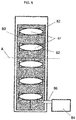
- the combustor valve 72 includes a valve element 80, which extends circumferentially about the engine central longitudinal axis A.
- the valve element 80 is a full ring, while in other embodiments the valve element 80 is segmented.
- the valve element 80 includes a plurality of valve openings 82.
- the valve element 80 is movable about the engine central longitudinal axis A to move the plurality of valve openings 82 into and out of alignment with bypass inlet openings 67 thus regulating flow through the bypass passage 64 via the valve openings 82.
- FIG. 6 schematically illustrates the combustor valve 72 in an open position, with the valve openings 82 aligned with the bypass inlet openings 66.
- FIG. 7 illustrates the combustor valve 72 in a closed position, with the valve openings 82 out of alignment with the bypass inlet openings 67 so the bypass inlet openings 67 are covered, preventing flow into the bypass passage 64. While a fully open position and a fully closed position are illustrated in FIG. 6 and FIG. 7 , respectively, it is to be appreciated that in some embodiments, the combustor valve 72 may have one or more intermediate, partially-open positions between the fully open position and the fully closed position in which the valve openings 82 are partially aligned with the bypass inlet openings 67.
- bypass inlet openings 67 and valve openings 82 illustrated are merely exemplary, and may be varied based on system requirements, allowing airflow bypass the combustor while also minimizing the aerodynamic effects on the combustor.
- valve element 80 is driven around the engine central longitudinal axis A by a valve actuator 84 connected to the valve element 80 either directly, or through a linkage arrangement 86.
- the valve actuator 84 drives movement of the valve element 80.
- the arrangements disclosed herein provide for adjusting mass flow of the airflow into the combustor 56 such that the combustor 56 operation is tolerant to changes of turbine flowpath D area. This stabilizes operation of the combustor while also attaining the benefits of the variable turbine flowpath D.
Landscapes
- Engineering & Computer Science (AREA)
- Chemical & Material Sciences (AREA)
- Combustion & Propulsion (AREA)
- Mechanical Engineering (AREA)
- General Engineering & Computer Science (AREA)
- Physics & Mathematics (AREA)
- Fluid Mechanics (AREA)
- Control Of Turbines (AREA)
Claims (15)
- Gasturbinentriebwerk (20), umfassend eine Motorlängsmittelachse (A) und einen Brennkammerabschnitt (26), der Folgendes umfasst:eine Brennkammer (56), die einen Brennkammerzulauf (62) aufweist;einen Brennkammerbypasskanal (64), der einen Kanalzulauf (66) aufweist, der stromaufwärts des Brennkammerzulaufs angeordnet ist, wobei der Brennkammerbypasskanal dazu konfiguriert ist, einen ausgewählten Bypassluftstrom (70) um die Brennkammer umzuleiten; undein Brennkammerbypassventil (72), das an dem Brennkammerbypasskanal angeordnet ist, um den ausgewählten Bypassluftstrom entlang dem Brennkammerbypasskanal zu steuern, wobei das Brennkammerbypassventil ein Ventilelement (80) beinhaltet, dadurch gekennzeichnet, dass sich das Ventilelement (80) umlaufend um die Motorlängsmittelachse (A) erstreckt und dazu konfiguriert ist, sich um die Motorlängsmittelachse (A) zu drehen, um eine oder mehrere Ventilöffnungen (82) in Bezug auf eine oder mehrere Bypasskanalöffnungen (67) zu bewegen.
- Gasturbinentriebwerk nach Anspruch 1, wobei das Ventilelement eine röhrenförmige Hülse ist, wobei die eine oder die mehreren Ventilöffnungen in der Hülse angeordnet sind.
- Gasturbinentriebwerk nach Anspruch 1 oder 2, wobei das Ventilelement durch einen oder mehrere Aktoren (84) um die Motorlängsmittelachse (A) angetrieben wird.
- Gasturbinentriebwerk nach Anspruch 1, 2 oder 3, wobei der Brennkammerzulauf dazu konfiguriert ist, sich in einem aerodynamisch gedrosselten Zustand zu befinden, wenn sich ein Strömungswegbereich einer Turbine mit variablem Querschnitt (54), die stromabwärts der Brennkammer angeordnet ist, bei einem Mindestbereich befindet.
- Gasturbinentriebwerk nach Anspruch 4, wobei das Brennkammerbypassventil stromaufwärts einer Drosselposition des Brennkammerzulaufs (62) angeordnet ist.
- Gasturbinentriebwerk nach Anspruch 4 oder 5, wobei das Brennkammerbypassventil dazu konfiguriert ist, sich von einer geschlossenen Stellung in Richtung einer vollständig geöffneten Stellung zu bewegen, wenn der Strömungswegbereich der Turbine mit variablem Querschnitt erhöht wird.
- Gasturbinentriebwerk nach einem der vorhergehenden Ansprüche, wobei das Brennkammerbypassventil an einem Kanalzulauf angeordnet ist.
- Gasturbinentriebwerk nach einem der vorhergehenden Ansprüche, wobei der Brennkammerbypasskanal einen Kanalauslass beinhaltet, der an einem Turbinenabschnitt (28) des Gasturbinentriebwerks angeordnet ist.
- Gasturbinentriebwerk (20) nach einem der Ansprüche 1 bis 7, umfassend:eine Turbine mit variablem Querschnitt (54), die derartig konfiguriert ist, dass ein Strömungswegbereich der Turbine mit variablem Querschnitt wahlweise veränderlich ist;wobei die Brennkammer stromaufwärts der Turbine mit variablem Querschnitt angeordnet ist, und der Kanalzulauf stromabwärts eines Verdichterabschnitts des Gasturbinentriebwerks angeordnet ist.
- Gasturbinentriebwerk nach Anspruch 9, wobei der Brennkammerzulauf dazu konfiguriert ist, sich in einem aerodynamisch gedrosselten Zustand zu befinden, wenn sich der Strömungswegbereich einer Turbine mit variablem Querschnitt bei einem Mindestbereich befindet.
- Gasturbinentriebwerk nach Anspruch 9 oder 10, wobei die Turbine mit variablem Querschnitt eine oder mehrere Turbinenschaufeln beinhaltet, wobei die eine oder die mehreren Turbinenschaufeln dazu konfiguriert sind, beweglich zu sein, wodurch der Strömungswegbereich verändert wird.
- Gasturbinentriebwerk nach Anspruch 11, wobei die eine oder die mehreren Turbinenschaufeln um eine Schaufelachse beweglich sind.
- Gasturbinentriebwerk nach einem der Ansprüche 9 bis 12, wobei der Brennkammerbypasskanal einen Kanalauslass beinhaltet, der an der Turbine mit variablem Querschnitt angeordnet ist.
- Verfahren zum Betreiben des Gasturbinentriebwerks (20) nach einem der Ansprüche 9 bis 13, umfassend:Einstellen eines Bereich eines Turbinenabschnitts (28) der Gasturbine; undBypassing, als Reaktion auf den Einstellschritt, eines Teils des zentralen Luftstroms, der in den Brennkammerabschnitt (26) um eine Brennkammer (56) gelangt.
- Verfahren nach Anspruch 14, wobei das Bypassing des Teils des zentralen Luftstroms Folgendes umfasst:Drehen eines Ventilelements (80) um einen Motorlängsmittelachse (A), um eine oder mehrere Ventilöffnungen (82) in Bezug auf eine oder mehrere Bypasskanalöffnungen (67) zu bewegen; undStrömen des Teils des zentralen Luftstroms durch die eine oder die mehreren Bypasskanalöffnungen über die eine oder die mehreren Ventilöffnungen.
Applications Claiming Priority (1)
| Application Number | Priority Date | Filing Date | Title |
|---|---|---|---|
| US15/864,266 US11060463B2 (en) | 2018-01-08 | 2018-01-08 | Modulated combustor bypass and combustor bypass valve |
Publications (2)
| Publication Number | Publication Date |
|---|---|
| EP3508790A1 EP3508790A1 (de) | 2019-07-10 |
| EP3508790B1 true EP3508790B1 (de) | 2021-04-21 |
Family
ID=65010624
Family Applications (1)
| Application Number | Title | Priority Date | Filing Date |
|---|---|---|---|
| EP19150786.2A Active EP3508790B1 (de) | 2018-01-08 | 2019-01-08 | Gasturbinenmotor mit einem modulierten brennkammer-bypass und einem brennkammer-bypassventil |
Country Status (2)
| Country | Link |
|---|---|
| US (1) | US11060463B2 (de) |
| EP (1) | EP3508790B1 (de) |
Families Citing this family (1)
| Publication number | Priority date | Publication date | Assignee | Title |
|---|---|---|---|---|
| CN115289499B (zh) * | 2022-10-08 | 2023-01-10 | 成都中科翼能科技有限公司 | 一种燃气轮机燃烧室进气口的空心支板 |
Citations (2)
| Publication number | Priority date | Publication date | Assignee | Title |
|---|---|---|---|---|
| US3958413A (en) * | 1974-09-03 | 1976-05-25 | General Motors Corporation | Combustion method and apparatus |
| US5557920A (en) * | 1993-12-22 | 1996-09-24 | Westinghouse Electric Corporation | Combustor bypass system for a gas turbine |
Family Cites Families (19)
| Publication number | Priority date | Publication date | Assignee | Title |
|---|---|---|---|---|
| US3899881A (en) * | 1974-02-04 | 1975-08-19 | Gen Motors Corp | Combustion apparatus with secondary air to vaporization chamber and concurrent variance of secondary air and dilution air in a reverse sense |
| US3930368A (en) * | 1974-12-12 | 1976-01-06 | General Motors Corporation | Combustion liner air valve |
| US5596871A (en) * | 1995-05-31 | 1997-01-28 | Alliedsignal Inc. | Deceleration fuel control system for a turbine engine |
| US5924276A (en) | 1996-07-17 | 1999-07-20 | Mowill; R. Jan | Premixer with dilution air bypass valve assembly |
| US6220035B1 (en) | 1997-09-15 | 2001-04-24 | Alliedsignal Inc. | Annular combustor tangential injection flame stabilizer |
| JP2003004233A (ja) * | 2001-06-26 | 2003-01-08 | Mitsubishi Heavy Ind Ltd | 圧縮空気のバイパス弁、およびガスタービン |
| SE523082C2 (sv) * | 2001-11-20 | 2004-03-23 | Volvo Aero Corp | Anordning vid en brännkammare hos en gasturbin för reglering av inflöde av gas till brännkammarens förbränningszon |
| JP2003329244A (ja) * | 2002-05-14 | 2003-11-19 | Mitsubishi Heavy Ind Ltd | ガスタービン用燃焼器及びその燃焼制御方法 |
| US7631504B2 (en) * | 2006-02-21 | 2009-12-15 | General Electric Company | Methods and apparatus for assembling gas turbine engines |
| US8522528B2 (en) * | 2008-06-30 | 2013-09-03 | Solar Turbines Inc. | System for diffusing bleed air flow |
| CN101769178A (zh) | 2009-11-05 | 2010-07-07 | 寿光市康跃增压器有限公司 | 旁通进气变截面涡轮机装置 |
| WO2014185997A2 (en) * | 2013-02-04 | 2014-11-20 | United Technologies Corporation | Rotary valve for bleed flow path |
| US9291350B2 (en) * | 2013-03-18 | 2016-03-22 | General Electric Company | System for providing a working fluid to a combustor |
| US10132191B2 (en) | 2013-08-21 | 2018-11-20 | United Technologies Corporation | Variable area turbine arrangement with secondary flow modulation |
| GB201414662D0 (en) * | 2014-08-19 | 2014-10-01 | Rolls Royce Plc | Method of operation of a gas turbine engine |
| US10619564B2 (en) * | 2015-11-26 | 2020-04-14 | Mitsubishi Hitachi Power Systems, Ltd. | Gas turbine and component-temperature adjustment method therefor |
| US10830438B2 (en) * | 2017-10-12 | 2020-11-10 | Raytheon Technologies Corporation | Modulated combustor bypass |
| US10954865B2 (en) * | 2018-06-19 | 2021-03-23 | The Boeing Company | Pressurized air systems for aircraft and related methods |
| US11530650B2 (en) * | 2018-07-13 | 2022-12-20 | Raytheon Technologies Corporation | Gas turbine engine with active variable turbine cooling |
-
2018
- 2018-01-08 US US15/864,266 patent/US11060463B2/en active Active
-
2019
- 2019-01-08 EP EP19150786.2A patent/EP3508790B1/de active Active
Patent Citations (2)
| Publication number | Priority date | Publication date | Assignee | Title |
|---|---|---|---|---|
| US3958413A (en) * | 1974-09-03 | 1976-05-25 | General Motors Corporation | Combustion method and apparatus |
| US5557920A (en) * | 1993-12-22 | 1996-09-24 | Westinghouse Electric Corporation | Combustor bypass system for a gas turbine |
Also Published As
| Publication number | Publication date |
|---|---|
| US20190211751A1 (en) | 2019-07-11 |
| US11060463B2 (en) | 2021-07-13 |
| EP3508790A1 (de) | 2019-07-10 |
Similar Documents
| Publication | Publication Date | Title |
|---|---|---|
| EP3406883B1 (de) | Aktiv gesteuerte entlüftungsquellenumschaltung | |
| EP2820255B1 (de) | Turbine mit variablem bereich | |
| US20160040550A1 (en) | Variable vane control system | |
| US10094229B2 (en) | Cooling system of a stator assembly for a gas turbine engine having a variable cooling flow mechanism and method of operation | |
| EP2957754B1 (de) | Düse mit variablem querschnitt für gasturbinenmotor | |
| EP3239493B1 (de) | Einfacher wärmetauscher mit superlegierungsmaterialien | |
| EP3406882B1 (de) | Aktive zapfströmungsmodulation | |
| EP3726010B1 (de) | Aktive multieffektorspaltsteuerung in hochdruckturbinen | |
| US9995217B2 (en) | Rotary valve for bleed flow path | |
| EP3470656B1 (de) | Modulierter brennkammer-bypass | |
| EP3296548B1 (de) | In einem zwischengehäuse montierten wärmetauscher für gasturbinenmotor | |
| EP2904218B1 (de) | Niederdruckverdichter mit verstellbaren leitschaufeln | |
| EP3508790B1 (de) | Gasturbinenmotor mit einem modulierten brennkammer-bypass und einem brennkammer-bypassventil | |
| EP3453830B1 (de) | Turbinenleitschaufelanordnung mit variablem bereich | |
| EP3623584B1 (de) | Stellschraubenspaltregelung zwischen festen und variablen schaufeln | |
| EP3460226B1 (de) | Bewegliche abgass-zentralkörper auskleidung | |
| EP3617460B1 (de) | Doppelventilsystem mit unterschiedlichen ventilscheibengeometrien |
Legal Events
| Date | Code | Title | Description |
|---|---|---|---|
| PUAI | Public reference made under article 153(3) epc to a published international application that has entered the european phase |
Free format text: ORIGINAL CODE: 0009012 |
|
| STAA | Information on the status of an ep patent application or granted ep patent |
Free format text: STATUS: THE APPLICATION HAS BEEN PUBLISHED |
|
| AK | Designated contracting states |
Kind code of ref document: A1 Designated state(s): AL AT BE BG CH CY CZ DE DK EE ES FI FR GB GR HR HU IE IS IT LI LT LU LV MC MK MT NL NO PL PT RO RS SE SI SK SM TR |
|
| AX | Request for extension of the european patent |
Extension state: BA ME |
|
| STAA | Information on the status of an ep patent application or granted ep patent |
Free format text: STATUS: REQUEST FOR EXAMINATION WAS MADE |
|
| 17P | Request for examination filed |
Effective date: 20191210 |
|
| RBV | Designated contracting states (corrected) |
Designated state(s): AL AT BE BG CH CY CZ DE DK EE ES FI FR GB GR HR HU IE IS IT LI LT LU LV MC MK MT NL NO PL PT RO RS SE SI SK SM TR |
|
| GRAP | Despatch of communication of intention to grant a patent |
Free format text: ORIGINAL CODE: EPIDOSNIGR1 |
|
| STAA | Information on the status of an ep patent application or granted ep patent |
Free format text: STATUS: GRANT OF PATENT IS INTENDED |
|
| INTG | Intention to grant announced |
Effective date: 20201105 |
|
| GRAS | Grant fee paid |
Free format text: ORIGINAL CODE: EPIDOSNIGR3 |
|
| GRAA | (expected) grant |
Free format text: ORIGINAL CODE: 0009210 |
|
| STAA | Information on the status of an ep patent application or granted ep patent |
Free format text: STATUS: THE PATENT HAS BEEN GRANTED |
|
| RAP1 | Party data changed (applicant data changed or rights of an application transferred) |
Owner name: RAYTHEON TECHNOLOGIES CORPORATION |
|
| AK | Designated contracting states |
Kind code of ref document: B1 Designated state(s): AL AT BE BG CH CY CZ DE DK EE ES FI FR GB GR HR HU IE IS IT LI LT LU LV MC MK MT NL NO PL PT RO RS SE SI SK SM TR |
|
| REG | Reference to a national code |
Ref country code: GB Ref legal event code: FG4D |
|
| REG | Reference to a national code |
Ref country code: CH Ref legal event code: EP |
|
| REG | Reference to a national code |
Ref country code: DE Ref legal event code: R096 Ref document number: 602019003939 Country of ref document: DE |
|
| REG | Reference to a national code |
Ref country code: IE Ref legal event code: FG4D |
|
| REG | Reference to a national code |
Ref country code: AT Ref legal event code: REF Ref document number: 1385020 Country of ref document: AT Kind code of ref document: T Effective date: 20210515 |
|
| REG | Reference to a national code |
Ref country code: LT Ref legal event code: MG9D |
|
| REG | Reference to a national code |
Ref country code: AT Ref legal event code: MK05 Ref document number: 1385020 Country of ref document: AT Kind code of ref document: T Effective date: 20210421 |
|
| REG | Reference to a national code |
Ref country code: NL Ref legal event code: MP Effective date: 20210421 |
|
| PG25 | Lapsed in a contracting state [announced via postgrant information from national office to epo] |
Ref country code: AT Free format text: LAPSE BECAUSE OF FAILURE TO SUBMIT A TRANSLATION OF THE DESCRIPTION OR TO PAY THE FEE WITHIN THE PRESCRIBED TIME-LIMIT Effective date: 20210421 Ref country code: BG Free format text: LAPSE BECAUSE OF FAILURE TO SUBMIT A TRANSLATION OF THE DESCRIPTION OR TO PAY THE FEE WITHIN THE PRESCRIBED TIME-LIMIT Effective date: 20210721 Ref country code: NL Free format text: LAPSE BECAUSE OF FAILURE TO SUBMIT A TRANSLATION OF THE DESCRIPTION OR TO PAY THE FEE WITHIN THE PRESCRIBED TIME-LIMIT Effective date: 20210421 Ref country code: HR Free format text: LAPSE BECAUSE OF FAILURE TO SUBMIT A TRANSLATION OF THE DESCRIPTION OR TO PAY THE FEE WITHIN THE PRESCRIBED TIME-LIMIT Effective date: 20210421 Ref country code: LT Free format text: LAPSE BECAUSE OF FAILURE TO SUBMIT A TRANSLATION OF THE DESCRIPTION OR TO PAY THE FEE WITHIN THE PRESCRIBED TIME-LIMIT Effective date: 20210421 Ref country code: FI Free format text: LAPSE BECAUSE OF FAILURE TO SUBMIT A TRANSLATION OF THE DESCRIPTION OR TO PAY THE FEE WITHIN THE PRESCRIBED TIME-LIMIT Effective date: 20210421 |
|
| PG25 | Lapsed in a contracting state [announced via postgrant information from national office to epo] |
Ref country code: GR Free format text: LAPSE BECAUSE OF FAILURE TO SUBMIT A TRANSLATION OF THE DESCRIPTION OR TO PAY THE FEE WITHIN THE PRESCRIBED TIME-LIMIT Effective date: 20210722 Ref country code: IS Free format text: LAPSE BECAUSE OF FAILURE TO SUBMIT A TRANSLATION OF THE DESCRIPTION OR TO PAY THE FEE WITHIN THE PRESCRIBED TIME-LIMIT Effective date: 20210821 Ref country code: PL Free format text: LAPSE BECAUSE OF FAILURE TO SUBMIT A TRANSLATION OF THE DESCRIPTION OR TO PAY THE FEE WITHIN THE PRESCRIBED TIME-LIMIT Effective date: 20210421 Ref country code: NO Free format text: LAPSE BECAUSE OF FAILURE TO SUBMIT A TRANSLATION OF THE DESCRIPTION OR TO PAY THE FEE WITHIN THE PRESCRIBED TIME-LIMIT Effective date: 20210721 Ref country code: LV Free format text: LAPSE BECAUSE OF FAILURE TO SUBMIT A TRANSLATION OF THE DESCRIPTION OR TO PAY THE FEE WITHIN THE PRESCRIBED TIME-LIMIT Effective date: 20210421 Ref country code: PT Free format text: LAPSE BECAUSE OF FAILURE TO SUBMIT A TRANSLATION OF THE DESCRIPTION OR TO PAY THE FEE WITHIN THE PRESCRIBED TIME-LIMIT Effective date: 20210823 Ref country code: SE Free format text: LAPSE BECAUSE OF FAILURE TO SUBMIT A TRANSLATION OF THE DESCRIPTION OR TO PAY THE FEE WITHIN THE PRESCRIBED TIME-LIMIT Effective date: 20210421 Ref country code: RS Free format text: LAPSE BECAUSE OF FAILURE TO SUBMIT A TRANSLATION OF THE DESCRIPTION OR TO PAY THE FEE WITHIN THE PRESCRIBED TIME-LIMIT Effective date: 20210421 |
|
| REG | Reference to a national code |
Ref country code: DE Ref legal event code: R097 Ref document number: 602019003939 Country of ref document: DE |
|
| PG25 | Lapsed in a contracting state [announced via postgrant information from national office to epo] |
Ref country code: SK Free format text: LAPSE BECAUSE OF FAILURE TO SUBMIT A TRANSLATION OF THE DESCRIPTION OR TO PAY THE FEE WITHIN THE PRESCRIBED TIME-LIMIT Effective date: 20210421 Ref country code: EE Free format text: LAPSE BECAUSE OF FAILURE TO SUBMIT A TRANSLATION OF THE DESCRIPTION OR TO PAY THE FEE WITHIN THE PRESCRIBED TIME-LIMIT Effective date: 20210421 Ref country code: ES Free format text: LAPSE BECAUSE OF FAILURE TO SUBMIT A TRANSLATION OF THE DESCRIPTION OR TO PAY THE FEE WITHIN THE PRESCRIBED TIME-LIMIT Effective date: 20210421 Ref country code: RO Free format text: LAPSE BECAUSE OF FAILURE TO SUBMIT A TRANSLATION OF THE DESCRIPTION OR TO PAY THE FEE WITHIN THE PRESCRIBED TIME-LIMIT Effective date: 20210421 Ref country code: SM Free format text: LAPSE BECAUSE OF FAILURE TO SUBMIT A TRANSLATION OF THE DESCRIPTION OR TO PAY THE FEE WITHIN THE PRESCRIBED TIME-LIMIT Effective date: 20210421 Ref country code: DK Free format text: LAPSE BECAUSE OF FAILURE TO SUBMIT A TRANSLATION OF THE DESCRIPTION OR TO PAY THE FEE WITHIN THE PRESCRIBED TIME-LIMIT Effective date: 20210421 Ref country code: CZ Free format text: LAPSE BECAUSE OF FAILURE TO SUBMIT A TRANSLATION OF THE DESCRIPTION OR TO PAY THE FEE WITHIN THE PRESCRIBED TIME-LIMIT Effective date: 20210421 |
|
| PLBE | No opposition filed within time limit |
Free format text: ORIGINAL CODE: 0009261 |
|
| STAA | Information on the status of an ep patent application or granted ep patent |
Free format text: STATUS: NO OPPOSITION FILED WITHIN TIME LIMIT |
|
| 26N | No opposition filed |
Effective date: 20220124 |
|
| PG25 | Lapsed in a contracting state [announced via postgrant information from national office to epo] |
Ref country code: IS Free format text: LAPSE BECAUSE OF FAILURE TO SUBMIT A TRANSLATION OF THE DESCRIPTION OR TO PAY THE FEE WITHIN THE PRESCRIBED TIME-LIMIT Effective date: 20210821 Ref country code: AL Free format text: LAPSE BECAUSE OF FAILURE TO SUBMIT A TRANSLATION OF THE DESCRIPTION OR TO PAY THE FEE WITHIN THE PRESCRIBED TIME-LIMIT Effective date: 20210421 |
|
| PG25 | Lapsed in a contracting state [announced via postgrant information from national office to epo] |
Ref country code: IT Free format text: LAPSE BECAUSE OF FAILURE TO SUBMIT A TRANSLATION OF THE DESCRIPTION OR TO PAY THE FEE WITHIN THE PRESCRIBED TIME-LIMIT Effective date: 20210421 |
|
| PG25 | Lapsed in a contracting state [announced via postgrant information from national office to epo] |
Ref country code: MC Free format text: LAPSE BECAUSE OF FAILURE TO SUBMIT A TRANSLATION OF THE DESCRIPTION OR TO PAY THE FEE WITHIN THE PRESCRIBED TIME-LIMIT Effective date: 20210421 |
|
| REG | Reference to a national code |
Ref country code: CH Ref legal event code: PL |
|
| REG | Reference to a national code |
Ref country code: BE Ref legal event code: MM Effective date: 20220131 |
|
| PG25 | Lapsed in a contracting state [announced via postgrant information from national office to epo] |
Ref country code: LU Free format text: LAPSE BECAUSE OF NON-PAYMENT OF DUE FEES Effective date: 20220108 |
|
| PG25 | Lapsed in a contracting state [announced via postgrant information from national office to epo] |
Ref country code: BE Free format text: LAPSE BECAUSE OF NON-PAYMENT OF DUE FEES Effective date: 20220131 |
|
| PG25 | Lapsed in a contracting state [announced via postgrant information from national office to epo] |
Ref country code: LI Free format text: LAPSE BECAUSE OF NON-PAYMENT OF DUE FEES Effective date: 20220131 Ref country code: CH Free format text: LAPSE BECAUSE OF NON-PAYMENT OF DUE FEES Effective date: 20220131 |
|
| PG25 | Lapsed in a contracting state [announced via postgrant information from national office to epo] |
Ref country code: IE Free format text: LAPSE BECAUSE OF NON-PAYMENT OF DUE FEES Effective date: 20220108 |
|
| PGFP | Annual fee paid to national office [announced via postgrant information from national office to epo] |
Ref country code: DE Payment date: 20221220 Year of fee payment: 5 |
|
| P01 | Opt-out of the competence of the unified patent court (upc) registered |
Effective date: 20230521 |
|
| PGFP | Annual fee paid to national office [announced via postgrant information from national office to epo] |
Ref country code: GB Payment date: 20231219 Year of fee payment: 6 |
|
| PGFP | Annual fee paid to national office [announced via postgrant information from national office to epo] |
Ref country code: FR Payment date: 20231219 Year of fee payment: 6 |
|
| PG25 | Lapsed in a contracting state [announced via postgrant information from national office to epo] |
Ref country code: HU Free format text: LAPSE BECAUSE OF FAILURE TO SUBMIT A TRANSLATION OF THE DESCRIPTION OR TO PAY THE FEE WITHIN THE PRESCRIBED TIME-LIMIT; INVALID AB INITIO Effective date: 20190108 |
|
| PG25 | Lapsed in a contracting state [announced via postgrant information from national office to epo] |
Ref country code: MK Free format text: LAPSE BECAUSE OF FAILURE TO SUBMIT A TRANSLATION OF THE DESCRIPTION OR TO PAY THE FEE WITHIN THE PRESCRIBED TIME-LIMIT Effective date: 20210421 Ref country code: CY Free format text: LAPSE BECAUSE OF FAILURE TO SUBMIT A TRANSLATION OF THE DESCRIPTION OR TO PAY THE FEE WITHIN THE PRESCRIBED TIME-LIMIT Effective date: 20210421 |
|
| PGFP | Annual fee paid to national office [announced via postgrant information from national office to epo] |
Ref country code: DE Payment date: 20231219 Year of fee payment: 6 |