EP3506465A1 - Electric machine - Google Patents
Electric machine Download PDFInfo
- Publication number
- EP3506465A1 EP3506465A1 EP18215115.9A EP18215115A EP3506465A1 EP 3506465 A1 EP3506465 A1 EP 3506465A1 EP 18215115 A EP18215115 A EP 18215115A EP 3506465 A1 EP3506465 A1 EP 3506465A1
- Authority
- EP
- European Patent Office
- Prior art keywords
- heat sink
- casing
- stator
- electric machine
- annular heat
- Prior art date
- Legal status (The legal status is an assumption and is not a legal conclusion. Google has not performed a legal analysis and makes no representation as to the accuracy of the status listed.)
- Granted
Links
- 238000004804 winding Methods 0.000 claims abstract description 19
- 238000000034 method Methods 0.000 claims description 6
- 239000000463 material Substances 0.000 claims description 5
- 238000000465 moulding Methods 0.000 claims description 4
- 239000004033 plastic Substances 0.000 claims description 4
- 230000008878 coupling Effects 0.000 claims description 3
- 238000010168 coupling process Methods 0.000 claims description 3
- 238000005859 coupling reaction Methods 0.000 claims description 3
- 238000003780 insertion Methods 0.000 claims description 2
- 230000037431 insertion Effects 0.000 claims description 2
- 239000000243 solution Substances 0.000 description 10
- 239000004020 conductor Substances 0.000 description 5
- 239000000945 filler Substances 0.000 description 5
- 239000004734 Polyphenylene sulfide Substances 0.000 description 4
- 229920000069 polyphenylene sulfide Polymers 0.000 description 4
- 230000006835 compression Effects 0.000 description 3
- 238000007906 compression Methods 0.000 description 3
- 238000010292 electrical insulation Methods 0.000 description 3
- 230000005294 ferromagnetic effect Effects 0.000 description 3
- 238000001816 cooling Methods 0.000 description 2
- WABPQHHGFIMREM-UHFFFAOYSA-N lead(0) Chemical compound [Pb] WABPQHHGFIMREM-UHFFFAOYSA-N 0.000 description 2
- OKTJSMMVPCPJKN-UHFFFAOYSA-N Carbon Chemical compound [C] OKTJSMMVPCPJKN-UHFFFAOYSA-N 0.000 description 1
- RYGMFSIKBFXOCR-UHFFFAOYSA-N Copper Chemical compound [Cu] RYGMFSIKBFXOCR-UHFFFAOYSA-N 0.000 description 1
- 239000011231 conductive filler Substances 0.000 description 1
- 229910052802 copper Inorganic materials 0.000 description 1
- 239000010949 copper Substances 0.000 description 1
- 230000000694 effects Effects 0.000 description 1
- 239000003302 ferromagnetic material Substances 0.000 description 1
- 229910002804 graphite Inorganic materials 0.000 description 1
- 239000010439 graphite Substances 0.000 description 1
- 230000017525 heat dissipation Effects 0.000 description 1
- 238000002347 injection Methods 0.000 description 1
- 239000007924 injection Substances 0.000 description 1
- 239000011810 insulating material Substances 0.000 description 1
- 238000003475 lamination Methods 0.000 description 1
- 230000021715 photosynthesis, light harvesting Effects 0.000 description 1
- 229920005989 resin Polymers 0.000 description 1
- 239000011347 resin Substances 0.000 description 1
Images


Classifications
-
- F—MECHANICAL ENGINEERING; LIGHTING; HEATING; WEAPONS; BLASTING
- F28—HEAT EXCHANGE IN GENERAL
- F28F—DETAILS OF HEAT-EXCHANGE AND HEAT-TRANSFER APPARATUS, OF GENERAL APPLICATION
- F28F21/00—Constructions of heat-exchange apparatus characterised by the selection of particular materials
- F28F21/06—Constructions of heat-exchange apparatus characterised by the selection of particular materials of plastics material
-
- H—ELECTRICITY
- H02—GENERATION; CONVERSION OR DISTRIBUTION OF ELECTRIC POWER
- H02K—DYNAMO-ELECTRIC MACHINES
- H02K1/00—Details of the magnetic circuit
- H02K1/06—Details of the magnetic circuit characterised by the shape, form or construction
- H02K1/12—Stationary parts of the magnetic circuit
- H02K1/14—Stator cores with salient poles
- H02K1/146—Stator cores with salient poles consisting of a generally annular yoke with salient poles
-
- H—ELECTRICITY
- H02—GENERATION; CONVERSION OR DISTRIBUTION OF ELECTRIC POWER
- H02K—DYNAMO-ELECTRIC MACHINES
- H02K1/00—Details of the magnetic circuit
- H02K1/06—Details of the magnetic circuit characterised by the shape, form or construction
- H02K1/12—Stationary parts of the magnetic circuit
- H02K1/18—Means for mounting or fastening magnetic stationary parts on to, or to, the stator structures
- H02K1/185—Means for mounting or fastening magnetic stationary parts on to, or to, the stator structures to outer stators
-
- H—ELECTRICITY
- H02—GENERATION; CONVERSION OR DISTRIBUTION OF ELECTRIC POWER
- H02K—DYNAMO-ELECTRIC MACHINES
- H02K15/00—Methods or apparatus specially adapted for manufacturing, assembling, maintaining or repairing of dynamo-electric machines
- H02K15/02—Methods or apparatus specially adapted for manufacturing, assembling, maintaining or repairing of dynamo-electric machines of stator or rotor bodies
- H02K15/022—Methods or apparatus specially adapted for manufacturing, assembling, maintaining or repairing of dynamo-electric machines of stator or rotor bodies with salient poles or claw-shaped poles
-
- H—ELECTRICITY
- H02—GENERATION; CONVERSION OR DISTRIBUTION OF ELECTRIC POWER
- H02K—DYNAMO-ELECTRIC MACHINES
- H02K15/00—Methods or apparatus specially adapted for manufacturing, assembling, maintaining or repairing of dynamo-electric machines
- H02K15/12—Impregnating, heating or drying of windings, stators, rotors or machines
-
- H—ELECTRICITY
- H02—GENERATION; CONVERSION OR DISTRIBUTION OF ELECTRIC POWER
- H02K—DYNAMO-ELECTRIC MACHINES
- H02K3/00—Details of windings
- H02K3/32—Windings characterised by the shape, form or construction of the insulation
- H02K3/34—Windings characterised by the shape, form or construction of the insulation between conductors or between conductor and core, e.g. slot insulation
- H02K3/345—Windings characterised by the shape, form or construction of the insulation between conductors or between conductor and core, e.g. slot insulation between conductor and core, e.g. slot insulation
-
- H—ELECTRICITY
- H02—GENERATION; CONVERSION OR DISTRIBUTION OF ELECTRIC POWER
- H02K—DYNAMO-ELECTRIC MACHINES
- H02K5/00—Casings; Enclosures; Supports
- H02K5/04—Casings or enclosures characterised by the shape, form or construction thereof
-
- H—ELECTRICITY
- H02—GENERATION; CONVERSION OR DISTRIBUTION OF ELECTRIC POWER
- H02K—DYNAMO-ELECTRIC MACHINES
- H02K9/00—Arrangements for cooling or ventilating
- H02K9/22—Arrangements for cooling or ventilating by solid heat conducting material embedded in, or arranged in contact with, the stator or rotor, e.g. heat bridges
- H02K9/223—Heat bridges
-
- H—ELECTRICITY
- H02—GENERATION; CONVERSION OR DISTRIBUTION OF ELECTRIC POWER
- H02K—DYNAMO-ELECTRIC MACHINES
- H02K9/00—Arrangements for cooling or ventilating
- H02K9/22—Arrangements for cooling or ventilating by solid heat conducting material embedded in, or arranged in contact with, the stator or rotor, e.g. heat bridges
- H02K9/227—Heat sinks
Definitions
- This disclosure relates to an electric machine and, more specifically, a rotary electric motor, for example used to drive a fan of an electric ventilator.
- the disclosure addresses technical field of electric ventilators for automotive applications used to remove heat from radiating bodies and the like.
- a prior art electric motor comprises a casing, housing a wound stator rigidly connected to the casing, and a rotor, for example of the type with permanent magnets, rotatably connected to the casing.
- An electronic module or electronic drive module, connected to the stator, is usually mounted in the casing to power the stator.
- the casing is closed by a cap to form a sealed container from which connecting pins protrude to allow powering the electronic drive circuitry.
- the windings of an electric machine are made up of a plurality of coils of conductive material, generally copper, in the form of lead wire wound round two or more pole pieces of the stator and/or rotor of the electric machine.
- the winding, which is traversed by electrical current, is insulated from the pole pieces, which are made of ferromagnetic material.
- the electrical current flowing through the winding may be high and, on account of the Joule effect, produces heat which propagates to the entire winding and to adjacent parts of the electric machine.
- the casing of the electric machine of that prior document comprises a base wall, transverse to the axis of rotation of the machine and provided with an annular projection projecting towards the inside of the casing.
- stator pack or ferromagnetic core
- annular contact surface extending radially towards the inside of the casing while the windings are in a heat exchanging relationship with the above mentioned annular projection.
- the above mentioned prior art motor comprises a layer of electrically insulating and thermally conductive material, interposed between the stator windings and the projection, in order to guarantee that there is adequate electrical insulation and to optimize heat exchange between the stator and the casing.
- the main purpose of this disclosure is to overcome the above-mentioned disadvantages.
- One aim of this solution is to propose an electric machine with an effective system for cooling the stator winding, hence the entire machine.
- Another aim of this solution is to provide a rotary electric machine which is easier to assemble than prior art solutions.
- a further aim of this solution is to provide a rotary electric machine which is more robust and dependable than prior art solutions.
- This disclosure relates to a rotary electric machine comprising:
- the electric machine comprises a thermally conductive and electrically insulating annular heat sink interposed between the stator and the base wall of the casing.
- the heat sink is advantageously abutted against the base wall of the casing and the stator coils are abutted, with an end portion of them, against the annular heat sink.
- the heat sink defines an abutment or stop member for the stator after the latter has been inserted into the casing.
- the annular heat sink may be a rigid ring interposed between the stator and the casing in the form of a circular crown.
- the stator is abutted against, and stopped by, the annular heat sink, which is made of materials suitable to withstand the thrust by which the stator is inserted into the casing without being damaged.
- the casing need not be provided with a stop for the pack of laminations, since the windings can be pushed against the annular heat sink.
- the annular heat sink comprises at least one cradle in which at least a first coil of the stator coils is preferably positioned.
- the cradle has a bottom portion, a first flank extending from the bottom portion towards the stator and a second flank, facing the first flank, extending from the bottom portion towards the stator.
- the coil is advantageously inserted, at least partly, between the first flank and the second flank, for example with an end portion of it.
- the coil can be inserted into the cradle and abutted or rested against the bottom portion of the cradle itself.
- the coil can be abutted or rested against the first flank and/or the second flank of the cradle.
- the annular heat sink preferably comprises a plurality of cradles, each for a corresponding stator coil.
- each coil is at least partly positioned in a respective cradle for example with an end portion of it.
- the cradles extend one after the other along the annular heat sink preferably uninterruptedly.
- the annular heat sink has a plurality of teeth extending towards the stator and each tooth separates adjacent cradles.
- Each tooth has a first flank, which defines a first flank of a cradle, and a second flank, which defines a second flank of that cradle, adjacent to the previous one, without interruption.
- the annular heat sink is provided with a plurality of through holes, preferably made at least partly in the bottom portion of a cradle or of all the cradles.
- the electric machine comprises a thermally conductive and electrically insulating paste, also known as "gap filler", interposed between the coils and the annular heat sink and/or between the annular heat sink and the casing in such a way as to optimize the heat exchange between the stator windings and the casing of the electric motor.
- a thermally conductive and electrically insulating paste also known as "gap filler”
- the possible presence of the above mentioned holes in the heat sink contributes to defining preferential channels for transferring heat, in addition to the heat transferred by the heat sink itself which, as mentioned above, is made of thermally conductive material.
- the base wall of the casing comprises at least one projection projecting towards the inside of the casing in a direction parallel to the axis of rotation of the motor.
- the projection may be an annular uninterrupted or broken projection and the annular heat sink is preferably abutted, at least partly, against the projection.
- the heat sink has a substantially flat face for engaging the projection (or the casing) and the cradles extend from the annular heat sink on the side opposite to the projection.
- the heat sink has a substantially flat face and a face on which the coil cradles are defined.
- the teeth which delimit the cradles extend from the face on which the cradles themselves are defined.
- the annular heat sink is obtained by moulding a plastic material, reinforced if necessary, having the required properties of electrical insulation, thermal conductivity and compression strength needed to be inserted between the stator and the casing of the motor.
- the annular heat sink may be made, for example, of LATICONTHER_80_GR_50 or CoolPoly® E5101 Thermally Conductive Polyphenylene Sulfide (PPS) or thermally conductive PET.
- PPS Thermally Conductive Polyphenylene Sulfide
- the annular heat sink may be co-moulded with the casing of the electric motor.
- the numeral 1 denotes a rotary electric machine - for example, a permanent magnet electric motor to which express reference is made without losing in generality.
- the machine 1 having an axis of rotation R, comprises a casing 2 and a cap, not illustrated, for closing the casing 2.
- the casing 2 has a base wall 3 transverse to the axis of rotation R and a side wall 4, preferably cylindrical, extending from the wall 3.
- the casing 2 and the cap fit together in a direction parallel to the axis of rotation R and form a closed container, preferably of the sealed type.
- the motor 1 comprises a stator 5, integral with the casing 2, and a permanent magnet rotor, not illustrated, connected rotatably to the casing 2 and to the cap.
- the rotor comprises a shaft having at least one end which protrudes from the container formed by the casing and the cap and to which a fan of an electric ventilator may be fixed, for example.
- the stator 5 comprises a plurality of pole pieces 6 and phase leads 7 wound around the pole pieces 6.
- phase leads 7 wound around the pole pieces 6 define a plurality of coils 8 which, in the example illustrated, constitute the stator winding 9.
- Each coil 8 has an end portion 10, facing towards the bottom of the casing 2, and an end portion 11 which are aligned with each other in a direction parallel to the axis R.
- the machine 1 comprises a thermally conductive and electrically insulating annular heat sink 12 interposed between the stator and the base wall 3 of the casing 2.
- the annular heat sink 12 is preferably made by moulding a plastic material such as, for example, LATICONTHER_80_GR_50 or CoolPoly® E5101 Thermally Conductive Polyphenylene Sulfide (PPS) or graphite reinforced PET, which confer the required performance in terms of electrical insulation, thermal conductivity and compression strength because, as explained below, the stator is abutted against the heat sink.
- a plastic material such as, for example, LATICONTHER_80_GR_50 or CoolPoly® E5101 Thermally Conductive Polyphenylene Sulfide (PPS) or graphite reinforced PET, which confer the required performance in terms of electrical insulation, thermal conductivity and compression strength because, as explained below, the stator is abutted against the heat sink.
- the heat sink 12 is co-moulded with the casing 2.
- the heat sink 12 is abutted against the base wall 3 and the coils 8 are abutted against the heat sink 12 on the side opposite the wall 3.
- the annular heat sink 12 defines an abutment or stop member for the stator 5 when the stator is inserted into the casing 2.
- the heat sink 12 is ring shaped and extends round the axis of rotation R of the motor 1.
- the heat sink 12 is inserted into the casing 2 coaxially with the stator 5.
- the heat sink 12 has a first face 12a directed towards the stator 5 and a second face 12b directed towards the base wall 3.
- the heat sink 12 has a radial extension substantially corresponding to the radial extension of the coils 8 in such a way that the coils 8 are abutted against the heat sink 12 for their full radial dimension so as to maximize the heat exchange surface between the stator 5 and the heat sink 12.
- the heat sink 12 is like an annular crown with substantially flat faces 12a and 12b.
- the coils are abutted against the face 12a while the face 12b is disposed against the base wall 3.
- the heat sink 12 comprises a plurality of cradles 13, each for a corresponding coil 8.
- Each cradle 13 is delimited by a pair of teeth 14 which extend from the face 12a of the heat sink 12.
- the cradles 13 follow each other, preferably uninterruptedly, along the face 12a of the heat sink 12 and each tooth 14 separates two adjacent cradles 13.
- the heat sink 12 has a plurality of teeth 14 which extend from the face 12a and each pair of teeth 14 encloses two or more coils 8; that is to say, not all the coils 8 have a respective cradle 13 or, in other words, each cradle 13 houses more than one coil 8.
- each coil 8 is at least partly positioned in a respective cradle 13 with its end portion 10.
- Each tooth 14 has a first flank 14a and a second flank 14b.
- the first and second flanks 14a, 14b of adjacent teeth 14 delimit a respective cradle 13; the teeth 14 and cradles 13 follow each other, preferably uninterruptedly, along the face 12a of the heat sink 12.
- each cradle 13 is delimited by the flanks 14a and 14b and by a bottom portion 15.
- flanks 14a and 14b extend from the bottom portion 15 towards the stator 5 and each coil 8 is inserted at least partly between the facing flanks 14a and 14b of the respective cradle 13.
- the coils 8 are abutted against the bottom portion 15 of the respective cradle 13.
- the coils 8, more specifically at least the end portion 10 thereof, are abutted against the flanks 14a, 14b of the respective cradle 13 in such a way as to maximize the heat exchange surface between each coil 8 and the respective cradle 13.
- the machine 1 comprises a thermally conductive and electrically insulating paste 16, for example a paste of the type known as "gap filler", interposed between the coils 8 and the heat sink 12, so as to fill any empty spaces and optimize heat exchange between the coils 8 and the heat sink 12.
- a thermally conductive and electrically insulating paste 16 for example a paste of the type known as "gap filler”
- the paste 16 is also disposed between the annular heat sink 12 and the casing 2, specifically the base wall 3 thereof, in order to fill any irregularities between the coupling surfaces and to optimize heat exchange between the heat sink 12 and the casing 2.
- the heat sink 12 has a plurality of through holes 17 which, in the embodiment illustrated by way of example, are preferably located in the bottom portion 15 of each cradle 13.
- the paste 16 is usually also disposed inside the holes 17, thereby defining additional heat exchange channels, through the paste 16, to transfer heat from the stator 5 to the casing 2.
- the face 12b of the heat sink 12 is abutted against the base wall 3 of the casing 2, preferably with the paste 16 interposed between the two.
- the face of the wall 3 directed towards the inside of the casing 2 is substantially flat and, in practice, the heat sink 12 is abutted against the bottom of the casing 2 and, with its face 12b, is coplanar with the wall 3.
- the base wall 3 has a projection 18 projecting towards the inside of the casing 2.
- the projection 18 is annular and has a top face 18a in the shape of an annular crown.
- the projection 18 extends away from the positioning plane of the base wall 3 towards a space inside the motor 1.
- the heat sink 12 is abutted with its face 12b against the projection 18, specifically against the face 18a and the paste 16 is interposed between the projection 18 and the heat sink 12.
- the heat sink 12 comprises an annular tooth 19 extending from the face 12b towards the wall 3 for example for centring the heat sink 12 on the projection 18.
- the heat flows from the stator 5 to the projection 18, that is, to the casing 2 by way of the heat sink 12; the projection 18 may also be cooled by air circulating inside the motor 1.
- a method for assembling an electric machine in any of the embodiments described above comprises positioning or interposing the annular heat sink 12 between the stator 5 and the casing 2 and inserting the stator into the casing.
- the stator 5 is pushed into the casing 2 until it compresses the heat sink 12 which, in practice, constitutes an abutment member which stops further insertion of the stator into the casing.
- the heat sink 12 is inserted into the casing 2 until it abuts against the base wall 3 thereof.
- the stator 5 is then pushed into the casing 2 until it abuts against the heat sink 12.
- the heat sink 12 may be co-moulded with the casing 2 inside the base wall 3 thereof.
- the ring or heat sink 12 is coupled to the stator 5 for example by interposing the paste 16 which holds it in place.
- stator 5 and the heat sink 12 are then inserted as one and pushed into the casing 2 until the heat sink 12 abuts against the base wall 3 of the casing, thus defining for the stator 5 the abutment member which stops it from being inserted further.
- the annular heat sink 12 of the electric machine of this solution is incompressible, in the sense that it is capable, without being damaged, of withstanding the thrust by which the stator 5 is inserted into the casing 2.
- the material used is, as mentioned, sufficiently rigid to compression to remain unaffected when the stator is inserted and to constitute an abutment member for the stator when the stator is inserted into the casing.
- stator can be pressed in against the heat sink without necessitating very precise clearances for coupling stator and casing to each other, which are expensive and complicated to obtain.
- the cradles maximize the heat exchange surface between the stator winding and the heat sink, especially in combination with the paste 16 since empty spaces, if any, are filled with gap filler.
- the heat sink 12 is made as a single ring, preferably of thermally conductive plastic.
- the ring or heat sink 12 is mounted on the stator 5 and held in place by the paste 16.
- the holes 17 allow the paste to pass through and the paste can also be spread on the face 12b when the assembly made up of stator and heat sink is inserted into the casing 2; preferably, a layer of paste 16 is also applied to the heat sink 12 on the side where the casing 2 is.
Abstract
- a casing (2) comprising a base wall (3);
- a stator (5) integral with the casing (2) and provided with a plurality of coils (8) constituting a stator winding (9),
- a thermally conductive and electrically insulating annular heat sink (12) interposed between the stator (5) and the base wall (3) of the casing; the annular heat sink (12) is abutted against the base wall (3) and the coils (8) are abutted against the annular heat sink (12) which defines a stop for the stator (5).
Description
- This disclosure relates to an electric machine and, more specifically, a rotary electric motor, for example used to drive a fan of an electric ventilator. The disclosure addresses technical field of electric ventilators for automotive applications used to remove heat from radiating bodies and the like.
- Generally speaking, a prior art electric motor comprises a casing, housing a wound stator rigidly connected to the casing, and a rotor, for example of the type with permanent magnets, rotatably connected to the casing.
- An electronic module or electronic drive module, connected to the stator, is usually mounted in the casing to power the stator.
- The casing is closed by a cap to form a sealed container from which connecting pins protrude to allow powering the electronic drive circuitry.
- It is known that the windings of an electric machine, be they stator windings or rotor windings, are made up of a plurality of coils of conductive material, generally copper, in the form of lead wire wound round two or more pole pieces of the stator and/or rotor of the electric machine. The winding, which is traversed by electrical current, is insulated from the pole pieces, which are made of ferromagnetic material.
- The electrical current flowing through the winding may be high and, on account of the Joule effect, produces heat which propagates to the entire winding and to adjacent parts of the electric machine.
- It has been found that the heat deteriorates the conductivity properties of the lead wire, resulting in higher resistance to the flow of current and causing high and often unacceptable energy dissipation.
- This situation is particularly serious with rotary electric machines of the sealed type where the windings are enclosed in the container, defined by casing and cap, where cooling air is not free to circulate.
- A solution intended to overcome these drawbacks is described in patent document
WO2015015461 in the name of the present Applicant. - The casing of the electric machine of that prior document comprises a base wall, transverse to the axis of rotation of the machine and provided with an annular projection projecting towards the inside of the casing.
- The stator pack, or ferromagnetic core, is abutted against an annular contact surface extending radially towards the inside of the casing while the windings are in a heat exchanging relationship with the above mentioned annular projection.
- The above mentioned prior art motor comprises a layer of electrically insulating and thermally conductive material, interposed between the stator windings and the projection, in order to guarantee that there is adequate electrical insulation and to optimize heat exchange between the stator and the casing.
- Another conceptually similar machine, that is to say, one with an abutment member for the ferromagnetic core and a layer of electrically insulating and thermally conductive material interposed between the stator windings and the casing, is disclosed in document
DE8915212 . - One disadvantage of the layouts of this kind is that when the stator is pressure-fitted into the casing, there is the risk of the insulating layer being damaged, for example by pointed tips in the windings, despite the contact surface for the ferromagnetic core, thus negatively affecting the operation of the motor.
- To overcome this drawback, a certain safety clearance must be maintained between the stator and the projection by suitably dimensioning the contact surface and assembly tolerances but thereby worsening the dissipating capabilities of the system. Moreover, especially in the case where the layer of insulating material is divided into separate sheets, each to be placed in the casing at a respective stator coil, assembling the electric machine is relatively complex.
- In prior art electric machines of a different kind, described for example in documents
EP2282395 orEP0327338 , heat dissipation is achieved by filling the gap between the stator and the casing with thermally conductive fillers, such as resins, for example, after the stator has been assembled into the casing and stopped against the corresponding abutment member. Besides the drawbacks due to assembly tolerances, these solutions also suffer from disadvantages connected with the injection of the fillers and which involve stringent processes to adequately limit dirtying the machine and equipment with the fillers themselves. - In this context, the main purpose of this disclosure is to overcome the above-mentioned disadvantages.
- One aim of this solution is to propose an electric machine with an effective system for cooling the stator winding, hence the entire machine.
- Another aim of this solution is to provide a rotary electric machine which is easier to assemble than prior art solutions.
- A further aim of this solution is to provide a rotary electric machine which is more robust and dependable than prior art solutions.
- The technical purpose and aims specified are substantially achieved by an electric machine according to claim 1.
- This disclosure relates to a rotary electric machine comprising:
- casing comprising a base wall which is transverse to the axis of rotation of the electric machine;
- cap for closing the casing;
- stator, integral with the casing and provided with a plurality of pole pieces and at least one lead wound around the pole pieces to define a plurality of coils constituting a stator winding.
- For simplicity, reference is hereinafter made to an electric motor as an example of a rotary electric machine but without thereby losing in generality. According to one aspect of the disclosure, the electric machine comprises a thermally conductive and electrically insulating annular heat sink interposed between the stator and the base wall of the casing.
- According to one aspect of the disclosure, the heat sink is advantageously abutted against the base wall of the casing and the stator coils are abutted, with an end portion of them, against the annular heat sink.
- Advantageously, the heat sink defines an abutment or stop member for the stator after the latter has been inserted into the casing.
- That way, it is not necessary to provide other abutment parts on the inside surface of the casing, heat exchange capacity is maximized and assembly tolerances are minimized.
- The annular heat sink may be a rigid ring interposed between the stator and the casing in the form of a circular crown.
- The stator is abutted against, and stopped by, the annular heat sink, which is made of materials suitable to withstand the thrust by which the stator is inserted into the casing without being damaged.
- As already mentioned, the casing need not be provided with a stop for the pack of laminations, since the windings can be pushed against the annular heat sink.
- According to one aspect of the disclosure, to maximize the heat exchange surface between the stator and the annular heat sink, the annular heat sink comprises at least one cradle in which at least a first coil of the stator coils is preferably positioned.
- According to one aspect of the disclosure, the cradle has a bottom portion, a first flank extending from the bottom portion towards the stator and a second flank, facing the first flank, extending from the bottom portion towards the stator.
- The coil is advantageously inserted, at least partly, between the first flank and the second flank, for example with an end portion of it.
- The coil can be inserted into the cradle and abutted or rested against the bottom portion of the cradle itself.
- According to one aspect of the disclosure, the coil can be abutted or rested against the first flank and/or the second flank of the cradle.
- The annular heat sink preferably comprises a plurality of cradles, each for a corresponding stator coil.
- According to one aspect of the disclosure, each coil is at least partly positioned in a respective cradle for example with an end portion of it.
- The cradles extend one after the other along the annular heat sink preferably uninterruptedly.
- In practice, according to one aspect of the disclosure, the annular heat sink has a plurality of teeth extending towards the stator and each tooth separates adjacent cradles.
- Each tooth has a first flank, which defines a first flank of a cradle, and a second flank, which defines a second flank of that cradle, adjacent to the previous one, without interruption.
- According to one aspect of the disclosure, the annular heat sink is provided with a plurality of through holes, preferably made at least partly in the bottom portion of a cradle or of all the cradles.
- According to one aspect of the disclosure, the electric machine comprises a thermally conductive and electrically insulating paste, also known as "gap filler", interposed between the coils and the annular heat sink and/or between the annular heat sink and the casing in such a way as to optimize the heat exchange between the stator windings and the casing of the electric motor.
- Advantageously, the possible presence of the above mentioned holes in the heat sink contributes to defining preferential channels for transferring heat, in addition to the heat transferred by the heat sink itself which, as mentioned above, is made of thermally conductive material.
- According to one aspect of the disclosure, the base wall of the casing comprises at least one projection projecting towards the inside of the casing in a direction parallel to the axis of rotation of the motor.
- The projection may be an annular uninterrupted or broken projection and the annular heat sink is preferably abutted, at least partly, against the projection.
- Preferably, the heat sink has a substantially flat face for engaging the projection (or the casing) and the cradles extend from the annular heat sink on the side opposite to the projection.
- According to one aspect of the disclosure, the heat sink has a substantially flat face and a face on which the coil cradles are defined. The teeth which delimit the cradles extend from the face on which the cradles themselves are defined.
- According to one aspect of the disclosure, the annular heat sink is obtained by moulding a plastic material, reinforced if necessary, having the required properties of electrical insulation, thermal conductivity and compression strength needed to be inserted between the stator and the casing of the motor.
- The annular heat sink may be made, for example, of LATICONTHER_80_GR_50 or CoolPoly® E5101 Thermally Conductive Polyphenylene Sulfide (PPS) or thermally conductive PET.
- According to one aspect of the disclosure, the annular heat sink may be co-moulded with the casing of the electric motor.
- Other features and advantages of the electric machine according to this disclosure are more apparent in the non-limiting description of a preferred but non-exclusive embodiment of it, as illustrated in the accompanying drawings, in which:
-
Figure 1 is a schematic exploded perspective view, with some parts cut away for greater clarity, of an electric machine according to this disclosure; -
Figure 2 is a schematic cross section, with some parts cut away for greater clarity, of an electric machine according to this disclosure; -
Figure 3 is a schematic perspective view of a portion of an electric machine according to this disclosure; -
Figure 4 is a plan view from above, with some parts cut away for greater clarity, of an electric machine according to this disclosure; -
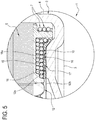
Figure 5 is a schematic cross section of a detail of an electric machine according to this disclosure. - With reference to the accompanying drawings, the numeral 1 denotes a rotary electric machine - for example, a permanent magnet electric motor to which express reference is made without losing in generality.
- The machine 1 is illustrated and described hereinafter only insofar as necessary for understanding this disclosure.
- The machine 1, having an axis of rotation R, comprises a
casing 2 and a cap, not illustrated, for closing thecasing 2. - The
casing 2 has abase wall 3 transverse to the axis of rotation R and aside wall 4, preferably cylindrical, extending from thewall 3. - The
casing 2 and the cap fit together in a direction parallel to the axis of rotation R and form a closed container, preferably of the sealed type. - The motor 1 comprises a
stator 5, integral with thecasing 2, and a permanent magnet rotor, not illustrated, connected rotatably to thecasing 2 and to the cap. - For example, the rotor comprises a shaft having at least one end which protrudes from the container formed by the casing and the cap and to which a fan of an electric ventilator may be fixed, for example.
- The
stator 5 comprises a plurality ofpole pieces 6 and phase leads 7 wound around thepole pieces 6. - The phase leads 7 wound around the
pole pieces 6 define a plurality ofcoils 8 which, in the example illustrated, constitute the stator winding 9. - Each
coil 8 has anend portion 10, facing towards the bottom of thecasing 2, and anend portion 11 which are aligned with each other in a direction parallel to the axis R. - The machine 1 comprises a thermally conductive and electrically insulating
annular heat sink 12 interposed between the stator and thebase wall 3 of thecasing 2. - The
annular heat sink 12 is preferably made by moulding a plastic material such as, for example, LATICONTHER_80_GR_50 or CoolPoly® E5101 Thermally Conductive Polyphenylene Sulfide (PPS) or graphite reinforced PET, which confer the required performance in terms of electrical insulation, thermal conductivity and compression strength because, as explained below, the stator is abutted against the heat sink. - In an alternative embodiment not illustrated, the
heat sink 12 is co-moulded with thecasing 2. - The
heat sink 12 is abutted against thebase wall 3 and thecoils 8 are abutted against theheat sink 12 on the side opposite thewall 3. According to this disclosure, theannular heat sink 12 defines an abutment or stop member for thestator 5 when the stator is inserted into thecasing 2. - The
heat sink 12 is ring shaped and extends round the axis of rotation R of the motor 1. - As illustrated, the
heat sink 12 is inserted into thecasing 2 coaxially with thestator 5. - The
heat sink 12 has afirst face 12a directed towards thestator 5 and asecond face 12b directed towards thebase wall 3. - Preferably, the
heat sink 12 has a radial extension substantially corresponding to the radial extension of thecoils 8 in such a way that thecoils 8 are abutted against theheat sink 12 for their full radial dimension so as to maximize the heat exchange surface between thestator 5 and theheat sink 12. - In an embodiment not illustrated, the
heat sink 12 is like an annular crown with substantiallyflat faces - In such a case, the coils are abutted against the
face 12a while theface 12b is disposed against thebase wall 3. - In the embodiment illustrated, the
heat sink 12 comprises a plurality ofcradles 13, each for acorresponding coil 8. - Each
cradle 13 is delimited by a pair ofteeth 14 which extend from theface 12a of theheat sink 12. - The
cradles 13 follow each other, preferably uninterruptedly, along theface 12a of theheat sink 12 and eachtooth 14 separates twoadjacent cradles 13. - In embodiments not illustrated, the
heat sink 12 has a plurality ofteeth 14 which extend from theface 12a and each pair ofteeth 14 encloses two ormore coils 8; that is to say, not all thecoils 8 have arespective cradle 13 or, in other words, eachcradle 13 houses more than onecoil 8. - In the preferred embodiment illustrated, each
coil 8 is at least partly positioned in arespective cradle 13 with itsend portion 10. - Each
tooth 14 has afirst flank 14a and asecond flank 14b. - The first and
second flanks adjacent teeth 14 delimit arespective cradle 13; theteeth 14 and cradles 13 follow each other, preferably uninterruptedly, along theface 12a of theheat sink 12. - Thus, each
cradle 13 is delimited by theflanks bottom portion 15. - The
flanks bottom portion 15 towards thestator 5 and eachcoil 8 is inserted at least partly between the facingflanks respective cradle 13. - In one embodiment, the
coils 8 are abutted against thebottom portion 15 of therespective cradle 13. - Preferably, the
coils 8, more specifically at least theend portion 10 thereof, are abutted against theflanks respective cradle 13 in such a way as to maximize the heat exchange surface between eachcoil 8 and therespective cradle 13. - As illustrated in particular in
Figure 5 , the machine 1 comprises a thermally conductive and electrically insulatingpaste 16, for example a paste of the type known as "gap filler", interposed between thecoils 8 and theheat sink 12, so as to fill any empty spaces and optimize heat exchange between thecoils 8 and theheat sink 12. - Preferably, the
paste 16 is also disposed between theannular heat sink 12 and thecasing 2, specifically thebase wall 3 thereof, in order to fill any irregularities between the coupling surfaces and to optimize heat exchange between theheat sink 12 and thecasing 2. - The
heat sink 12 has a plurality of throughholes 17 which, in the embodiment illustrated by way of example, are preferably located in thebottom portion 15 of eachcradle 13. - The
paste 16 is usually also disposed inside theholes 17, thereby defining additional heat exchange channels, through thepaste 16, to transfer heat from thestator 5 to thecasing 2. - As mentioned, the
face 12b of theheat sink 12 is abutted against thebase wall 3 of thecasing 2, preferably with thepaste 16 interposed between the two. - In an embodiment not illustrated, the face of the
wall 3 directed towards the inside of thecasing 2 is substantially flat and, in practice, theheat sink 12 is abutted against the bottom of thecasing 2 and, with itsface 12b, is coplanar with thewall 3. - In the embodiment illustrated in particular in
Figure 5 , for example, it may be observed that thebase wall 3 has aprojection 18 projecting towards the inside of thecasing 2. - The
projection 18 is annular and has atop face 18a in the shape of an annular crown. - In other words, the
projection 18 extends away from the positioning plane of thebase wall 3 towards a space inside the motor 1. - The
heat sink 12 is abutted with itsface 12b against theprojection 18, specifically against theface 18a and thepaste 16 is interposed between theprojection 18 and theheat sink 12. - In the embodiment illustrated, the
heat sink 12 comprises an annular tooth 19 extending from theface 12b towards thewall 3 for example for centring theheat sink 12 on theprojection 18. - That way, the heat flows from the
stator 5 to theprojection 18, that is, to thecasing 2 by way of theheat sink 12; theprojection 18 may also be cooled by air circulating inside the motor 1. - A method for assembling an electric machine in any of the embodiments described above comprises positioning or interposing the
annular heat sink 12 between thestator 5 and thecasing 2 and inserting the stator into the casing. - The
stator 5 is pushed into thecasing 2 until it compresses theheat sink 12 which, in practice, constitutes an abutment member which stops further insertion of the stator into the casing. - In an embodiment, the
heat sink 12 is inserted into thecasing 2 until it abuts against thebase wall 3 thereof. - The
stator 5 is then pushed into thecasing 2 until it abuts against theheat sink 12. - In an embodiment, as already mentioned, the
heat sink 12 may be co-moulded with thecasing 2 inside thebase wall 3 thereof. - In an embodiment, the ring or
heat sink 12 is coupled to thestator 5 for example by interposing thepaste 16 which holds it in place. - The
stator 5 and theheat sink 12 are then inserted as one and pushed into thecasing 2 until theheat sink 12 abuts against thebase wall 3 of the casing, thus defining for thestator 5 the abutment member which stops it from being inserted further. - Advantageously, compared to the solutions with the layer of electrically insulating and thermally conductive material - which require an abutment member made, for example, in the casing so as not to compress the insulating layer - the
annular heat sink 12 of the electric machine of this solution is incompressible, in the sense that it is capable, without being damaged, of withstanding the thrust by which thestator 5 is inserted into thecasing 2. - The material used is, as mentioned, sufficiently rigid to compression to remain unaffected when the stator is inserted and to constitute an abutment member for the stator when the stator is inserted into the casing.
- That way, the stator can be pressed in against the heat sink without necessitating very precise clearances for coupling stator and casing to each other, which are expensive and complicated to obtain.
- Assembly of the machine 1 is simplified, there is no longer any need to have special tolerances between stator and casing and to take into account thermal resistance variations due precisely to mechanical tolerances which, in prior art solutions, do not allow the stator and the casing to be effectively coupled thermally to each other.
- The cradles maximize the heat exchange surface between the stator winding and the heat sink, especially in combination with the
paste 16 since empty spaces, if any, are filled with gap filler. - The
heat sink 12 is made as a single ring, preferably of thermally conductive plastic. - In a preferred mode of assembling the machine 1, the ring or
heat sink 12 is mounted on thestator 5 and held in place by thepaste 16. - The
holes 17 allow the paste to pass through and the paste can also be spread on theface 12b when the assembly made up of stator and heat sink is inserted into thecasing 2; preferably, a layer ofpaste 16 is also applied to theheat sink 12 on the side where thecasing 2 is.
Claims (17)
- An electric machine having an axis of rotation (R) and comprising:- a casing (2) comprising a base wall (3) which is transverse to the axis of rotation (R);- a stator (5), integral with the casing (2) and provided with a plurality of pole pieces (6) and at least one lead (7) wound around the pole pieces (6) to define a plurality of coils (8) constituting a stator winding (9);the electric machine being characterized in that it comprises a thermally conductive and electrically insulating annular heat sink (12) interposed between the stator (5) and the base wall (3) of the casing; the annular heat sink (12) being abutted against the base wall (3) and the coils (8) being abutted against the annular heat sink (12), the annular heat sink (12) defining a stop or abutment member for the stator (5) against the casing (2).
- The electric machine according to claim 1, wherein the annular heat sink (12) comprises at least one cradle (13) for at least a first coil of the coils (8); the first coil being at least partly positioned in the cradle (13).
- The electric machine according to claim 2, wherein the cradle (13) has a bottom portion (15), a first flank (14a) extending from the bottom portion (15) towards the stator (5) and a second flank (14b), facing the first flank (14a), extending from the bottom portion (15) towards the stator (5), the first coil being at least partly inserted between the first flank (14a) and the second flank (14b).
- The electric machine according to claim 3, wherein the first coil is abutted against the bottom portion (15) of the cradle (13).
- The electric machine according to claim 3 or 4, wherein the first coil is abutted against the first flank (14a) and/or against the second flank (14b) of the cradle (13).
- The electric machine according to any one of the preceding claims, wherein the annular heat sink (12) is provided with a plurality of through holes (17).
- The electric machine according to claims 3 and 6, wherein the through holes (17) are provided at least partly on the bottom portion (15) of the cradle (13).
- The electric machine according to any one of the preceding claims, wherein the annular heat sink (12) comprises a plurality of cradles (13), each for a corresponding coil (8), each coil (8) being at least partly positioned in a respective cradle (13).
- The electric machine according to claim 8, wherein the cradles (13) follow each other uninterruptedly along the annular heat sink (12).
- The electric machine according to any one of the preceding claims, comprising a thermally conductive and electrically insulating paste (16) interposed between the coils (8) and the heat sink (12) and/or between the heat sink (12) and the casing (2).
- The electric machine according to any one of the preceding claims, wherein the base wall (3) comprises at least one projection (18) projecting towards the inside of the casing (2) in a direction parallel to the axis of rotation (R), the annular heat sink (12) being abutted at least partly against the projection (18).
- The electric machine according to any one of the preceding claims, wherein the annular heat sink (12) is made by moulding a plastic material.
- The electric machine according to any one of the preceding claims, wherein the annular heat sink (12) is co-moulded with the casing (2).
- A method for assembling an electric machine according to any one of the preceding claims, comprising the steps of: positioning the annular heat sink (12) between the stator (5) and the base wall (3) of the casing (2); inserting the stator (5) into the casing (2) until it compresses the heat sink (12) between the stator (5) and the base wall (3), the annular heat sink (12) defining an abutment or stop member which prevents further insertion of the stator (5) into the casing (2).
- The assembly method according to claim 14, wherein the step of positioning the annular heat sink (12) between the stator (5) and the base wall (3) of the casing (2) comprises the step of inserting the annular heat sink (12) into the casing (2) before inserting the stator (5) into the casing (2).
- The assembly method according to claim 14, wherein the step of positioning the annular heat sink (12) between the stator (5) and the base wall (3) of the casing (2) comprises the step of coupling the annular heat sink (12) to the stator (5) before inserting the stator (5) into the casing (2).
- The assembly method according to claim 14, wherein the step of positioning the annular heat sink (12) between the stator (5) and the base wall (3) of the casing (2) comprises the step of co-moulding the annular heat sink (12) with the casing (2).
Priority Applications (1)
| Application Number | Priority Date | Filing Date | Title |
|---|---|---|---|
| EP23162113.7A EP4216405A3 (en) | 2017-12-28 | 2018-12-21 | Electric machine |
Applications Claiming Priority (1)
| Application Number | Priority Date | Filing Date | Title |
|---|---|---|---|
| IT201700150291 | 2017-12-28 |
Related Child Applications (2)
| Application Number | Title | Priority Date | Filing Date |
|---|---|---|---|
| EP23162113.7A Division-Into EP4216405A3 (en) | 2017-12-28 | 2018-12-21 | Electric machine |
| EP23162113.7A Division EP4216405A3 (en) | 2017-12-28 | 2018-12-21 | Electric machine |
Publications (2)
| Publication Number | Publication Date |
|---|---|
| EP3506465A1 true EP3506465A1 (en) | 2019-07-03 |
| EP3506465B1 EP3506465B1 (en) | 2023-05-03 |
Family
ID=61731776
Family Applications (2)
| Application Number | Title | Priority Date | Filing Date |
|---|---|---|---|
| EP23162113.7A Pending EP4216405A3 (en) | 2017-12-28 | 2018-12-21 | Electric machine |
| EP18215115.9A Active EP3506465B1 (en) | 2017-12-28 | 2018-12-21 | Electric machine |
Family Applications Before (1)
| Application Number | Title | Priority Date | Filing Date |
|---|---|---|---|
| EP23162113.7A Pending EP4216405A3 (en) | 2017-12-28 | 2018-12-21 | Electric machine |
Country Status (3)
| Country | Link |
|---|---|
| US (1) | US11088597B2 (en) |
| EP (2) | EP4216405A3 (en) |
| CN (1) | CN109980855A (en) |
Cited By (2)
| Publication number | Priority date | Publication date | Assignee | Title |
|---|---|---|---|---|
| CN114499077A (en) * | 2022-04-15 | 2022-05-13 | 广州市创智机电设备有限公司 | Stator assembling equipment for double motors of new energy automobile |
| IT202100002522A1 (en) | 2021-02-04 | 2022-08-04 | Spal Automotive Srl | STATOR OF ELECTRIC MACHINE. |
Families Citing this family (2)
| Publication number | Priority date | Publication date | Assignee | Title |
|---|---|---|---|---|
| EP3975384B1 (en) * | 2020-09-25 | 2024-01-17 | Etel S.A. | Coil support for a rotary electric motor |
| CN112737155B (en) * | 2020-12-28 | 2022-03-01 | 安徽美芝精密制造有限公司 | Stator, motor, compressor and refrigeration plant |
Citations (6)
| Publication number | Priority date | Publication date | Assignee | Title |
|---|---|---|---|---|
| EP0327338A2 (en) | 1988-02-03 | 1989-08-09 | Mitsubishi Denki Kabushiki Kaisha | Vehicular AC generator and manufacturing method therefor |
| DE8915212U1 (en) | 1989-07-08 | 1990-10-31 | Robert Bosch Gmbh, 7000 Stuttgart, De | |
| JP2000116063A (en) * | 1998-10-05 | 2000-04-21 | Matsushita Electric Ind Co Ltd | Motor |
| EP2282395A2 (en) | 2009-07-29 | 2011-02-09 | Joy Ride Tech. Co., Ltd. | Motor Assembly with a thermally conducive bridging member |
| JP2013126292A (en) * | 2011-12-14 | 2013-06-24 | Panasonic Corp | Electric motor |
| WO2015015461A2 (en) | 2013-08-01 | 2015-02-05 | Spal Automotive S.R.L. | Electrical machine |
Family Cites Families (11)
| Publication number | Priority date | Publication date | Assignee | Title |
|---|---|---|---|---|
| US4451749A (en) * | 1981-09-11 | 1984-05-29 | Nippondenso Co., Ltd. | AC Generator |
| US6201321B1 (en) * | 1998-06-05 | 2001-03-13 | Bayside Controls, Inc. | Apparatus and method for dissipating heat from a motor |
| BE1015766A3 (en) * | 2003-11-05 | 2005-08-02 | Atlas Copco Airpower Nv | |
| JP2008193764A (en) * | 2007-02-01 | 2008-08-21 | Tamagawa Seiki Co Ltd | Stator structure |
| ITBO20070576A1 (en) * | 2007-08-07 | 2009-02-08 | Spal Automotive Srl | ELECTRIC MACHINE. |
| JP4450050B2 (en) * | 2007-11-07 | 2010-04-14 | トヨタ自動車株式会社 | Motor cooling structure |
| US8063547B2 (en) * | 2008-07-28 | 2011-11-22 | Kabushiki Kaisha Yaskawa Denki | Rotating electric machine and manufacturing method thereof |
| JP6194877B2 (en) * | 2014-12-19 | 2017-09-13 | トヨタ自動車株式会社 | Rotating electric machine |
| JP6476384B2 (en) * | 2015-01-20 | 2019-03-06 | 多摩川精機株式会社 | Resolver |
| JP5955437B1 (en) * | 2015-04-27 | 2016-07-20 | 三菱電機株式会社 | Rotating electric machine |
| CN206775327U (en) * | 2017-06-09 | 2017-12-19 | 罗寿元 | A kind of electric car natural cooling radiating motor |
-
2018
- 2018-12-20 US US16/227,035 patent/US11088597B2/en active Active
- 2018-12-21 EP EP23162113.7A patent/EP4216405A3/en active Pending
- 2018-12-21 EP EP18215115.9A patent/EP3506465B1/en active Active
- 2018-12-28 CN CN201811628505.7A patent/CN109980855A/en active Pending
Patent Citations (6)
| Publication number | Priority date | Publication date | Assignee | Title |
|---|---|---|---|---|
| EP0327338A2 (en) | 1988-02-03 | 1989-08-09 | Mitsubishi Denki Kabushiki Kaisha | Vehicular AC generator and manufacturing method therefor |
| DE8915212U1 (en) | 1989-07-08 | 1990-10-31 | Robert Bosch Gmbh, 7000 Stuttgart, De | |
| JP2000116063A (en) * | 1998-10-05 | 2000-04-21 | Matsushita Electric Ind Co Ltd | Motor |
| EP2282395A2 (en) | 2009-07-29 | 2011-02-09 | Joy Ride Tech. Co., Ltd. | Motor Assembly with a thermally conducive bridging member |
| JP2013126292A (en) * | 2011-12-14 | 2013-06-24 | Panasonic Corp | Electric motor |
| WO2015015461A2 (en) | 2013-08-01 | 2015-02-05 | Spal Automotive S.R.L. | Electrical machine |
Cited By (5)
| Publication number | Priority date | Publication date | Assignee | Title |
|---|---|---|---|---|
| IT202100002522A1 (en) | 2021-02-04 | 2022-08-04 | Spal Automotive Srl | STATOR OF ELECTRIC MACHINE. |
| EP4040648A1 (en) | 2021-02-04 | 2022-08-10 | SPAL Automotive S.r.l. | Stator of electric machine |
| US20220271579A1 (en) * | 2021-02-04 | 2022-08-25 | Spal Automotive S.R.L. | Stator of electric machine |
| CN114499077A (en) * | 2022-04-15 | 2022-05-13 | 广州市创智机电设备有限公司 | Stator assembling equipment for double motors of new energy automobile |
| CN114499077B (en) * | 2022-04-15 | 2022-06-21 | 广州市创智机电设备有限公司 | Stator assembling equipment for double motors of new energy automobile |
Also Published As
| Publication number | Publication date |
|---|---|
| US20190207483A1 (en) | 2019-07-04 |
| US11088597B2 (en) | 2021-08-10 |
| EP3506465B1 (en) | 2023-05-03 |
| CN109980855A (en) | 2019-07-05 |
| EP4216405A3 (en) | 2023-11-08 |
| EP4216405A2 (en) | 2023-07-26 |
Similar Documents
| Publication | Publication Date | Title |
|---|---|---|
| EP3506465B1 (en) | Electric machine | |
| CN109478808B (en) | Stator for axial flux machine and method for producing the same | |
| JP2023089193A (en) | Electric machine stator cooling systems and methods | |
| CN108604850B (en) | Rotating electrical machine | |
| US8264107B2 (en) | AFPM coreless multi-generator and motor | |
| CN203827121U (en) | Motor | |
| US11923739B1 (en) | Electric motor with bar wound stator and end turn cooling | |
| US20140139059A1 (en) | Rotating electric machine and related packaging method | |
| JP5267091B2 (en) | Stator for rotating electrical machine | |
| EP2645548A2 (en) | IPM rotary electric machine with thermally conductive compound | |
| US7812498B2 (en) | Stator of electric rotating machine and electric rotating machine | |
| US20090015094A1 (en) | Electrical rotary machine and method of manufacturing the same | |
| CN110178289B (en) | Rotor, motor, air conditioner, and method for manufacturing rotor | |
| KR20130029731A (en) | Electric machine module cooling system and method | |
| CN103460568B (en) | Electric rotating machine | |
| US20100244617A1 (en) | Stator having improved structure for restricting relative displacement between stator core and stator coil | |
| US20140132094A1 (en) | Thermal management of an ipm motor with non-magnetic bars | |
| JP6692494B2 (en) | Rotor, electric motor and air conditioner | |
| CN111712993A (en) | External stator of an electric motor having stator tooth groups, each stator tooth group having two adjacent stator teeth and a connecting yoke | |
| CN107112840B (en) | Stator for an electric motor | |
| JPH1051989A (en) | Mold type motor | |
| EP4040648A1 (en) | Stator of electric machine | |
| JP2010141960A (en) | Insulating member | |
| CN212343443U (en) | Stator structure and motor | |
| CN220711196U (en) | Rotor for axial flux motor, axial flux motor and high voltage fan |
Legal Events
| Date | Code | Title | Description |
|---|---|---|---|
| PUAI | Public reference made under article 153(3) epc to a published international application that has entered the european phase |
Free format text: ORIGINAL CODE: 0009012 |
|
| STAA | Information on the status of an ep patent application or granted ep patent |
Free format text: STATUS: THE APPLICATION HAS BEEN PUBLISHED |
|
| AK | Designated contracting states |
Kind code of ref document: A1 Designated state(s): AL AT BE BG CH CY CZ DE DK EE ES FI FR GB GR HR HU IE IS IT LI LT LU LV MC MK MT NL NO PL PT RO RS SE SI SK SM TR |
|
| AX | Request for extension of the european patent |
Extension state: BA ME |
|
| STAA | Information on the status of an ep patent application or granted ep patent |
Free format text: STATUS: REQUEST FOR EXAMINATION WAS MADE |
|
| 17P | Request for examination filed |
Effective date: 20191231 |
|
| RBV | Designated contracting states (corrected) |
Designated state(s): AL AT BE BG CH CY CZ DE DK EE ES FI FR GB GR HR HU IE IS IT LI LT LU LV MC MK MT NL NO PL PT RO RS SE SI SK SM TR |
|
| STAA | Information on the status of an ep patent application or granted ep patent |
Free format text: STATUS: EXAMINATION IS IN PROGRESS |
|
| 17Q | First examination report despatched |
Effective date: 20200504 |
|
| STAA | Information on the status of an ep patent application or granted ep patent |
Free format text: STATUS: EXAMINATION IS IN PROGRESS |
|
| GRAP | Despatch of communication of intention to grant a patent |
Free format text: ORIGINAL CODE: EPIDOSNIGR1 |
|
| STAA | Information on the status of an ep patent application or granted ep patent |
Free format text: STATUS: GRANT OF PATENT IS INTENDED |
|
| INTG | Intention to grant announced |
Effective date: 20221118 |
|
| GRAS | Grant fee paid |
Free format text: ORIGINAL CODE: EPIDOSNIGR3 |
|
| GRAA | (expected) grant |
Free format text: ORIGINAL CODE: 0009210 |
|
| STAA | Information on the status of an ep patent application or granted ep patent |
Free format text: STATUS: THE PATENT HAS BEEN GRANTED |
|
| AK | Designated contracting states |
Kind code of ref document: B1 Designated state(s): AL AT BE BG CH CY CZ DE DK EE ES FI FR GB GR HR HU IE IS IT LI LT LU LV MC MK MT NL NO PL PT RO RS SE SI SK SM TR |
|
| REG | Reference to a national code |
Ref country code: GB Ref legal event code: FG4D |
|
| REG | Reference to a national code |
Ref country code: DE Ref legal event code: R096 Ref document number: 602018049158 Country of ref document: DE |
|
| REG | Reference to a national code |
Ref country code: AT Ref legal event code: REF Ref document number: 1565521 Country of ref document: AT Kind code of ref document: T Effective date: 20230515 Ref country code: CH Ref legal event code: EP |
|
| REG | Reference to a national code |
Ref country code: IE Ref legal event code: FG4D |
|
| P01 | Opt-out of the competence of the unified patent court (upc) registered |
Effective date: 20230526 |
|
| REG | Reference to a national code |
Ref country code: LT Ref legal event code: MG9D |
|
| REG | Reference to a national code |
Ref country code: NL Ref legal event code: MP Effective date: 20230503 |
|
| REG | Reference to a national code |
Ref country code: AT Ref legal event code: MK05 Ref document number: 1565521 Country of ref document: AT Kind code of ref document: T Effective date: 20230503 |
|
| PG25 | Lapsed in a contracting state [announced via postgrant information from national office to epo] |
Ref country code: SE Free format text: LAPSE BECAUSE OF FAILURE TO SUBMIT A TRANSLATION OF THE DESCRIPTION OR TO PAY THE FEE WITHIN THE PRESCRIBED TIME-LIMIT Effective date: 20230503 Ref country code: PT Free format text: LAPSE BECAUSE OF FAILURE TO SUBMIT A TRANSLATION OF THE DESCRIPTION OR TO PAY THE FEE WITHIN THE PRESCRIBED TIME-LIMIT Effective date: 20230904 Ref country code: NO Free format text: LAPSE BECAUSE OF FAILURE TO SUBMIT A TRANSLATION OF THE DESCRIPTION OR TO PAY THE FEE WITHIN THE PRESCRIBED TIME-LIMIT Effective date: 20230803 Ref country code: NL Free format text: LAPSE BECAUSE OF FAILURE TO SUBMIT A TRANSLATION OF THE DESCRIPTION OR TO PAY THE FEE WITHIN THE PRESCRIBED TIME-LIMIT Effective date: 20230503 Ref country code: ES Free format text: LAPSE BECAUSE OF FAILURE TO SUBMIT A TRANSLATION OF THE DESCRIPTION OR TO PAY THE FEE WITHIN THE PRESCRIBED TIME-LIMIT Effective date: 20230503 Ref country code: AT Free format text: LAPSE BECAUSE OF FAILURE TO SUBMIT A TRANSLATION OF THE DESCRIPTION OR TO PAY THE FEE WITHIN THE PRESCRIBED TIME-LIMIT Effective date: 20230503 |
|
| PG25 | Lapsed in a contracting state [announced via postgrant information from national office to epo] |
Ref country code: RS Free format text: LAPSE BECAUSE OF FAILURE TO SUBMIT A TRANSLATION OF THE DESCRIPTION OR TO PAY THE FEE WITHIN THE PRESCRIBED TIME-LIMIT Effective date: 20230503 Ref country code: PL Free format text: LAPSE BECAUSE OF FAILURE TO SUBMIT A TRANSLATION OF THE DESCRIPTION OR TO PAY THE FEE WITHIN THE PRESCRIBED TIME-LIMIT Effective date: 20230503 Ref country code: LV Free format text: LAPSE BECAUSE OF FAILURE TO SUBMIT A TRANSLATION OF THE DESCRIPTION OR TO PAY THE FEE WITHIN THE PRESCRIBED TIME-LIMIT Effective date: 20230503 Ref country code: LT Free format text: LAPSE BECAUSE OF FAILURE TO SUBMIT A TRANSLATION OF THE DESCRIPTION OR TO PAY THE FEE WITHIN THE PRESCRIBED TIME-LIMIT Effective date: 20230503 Ref country code: IS Free format text: LAPSE BECAUSE OF FAILURE TO SUBMIT A TRANSLATION OF THE DESCRIPTION OR TO PAY THE FEE WITHIN THE PRESCRIBED TIME-LIMIT Effective date: 20230903 Ref country code: HR Free format text: LAPSE BECAUSE OF FAILURE TO SUBMIT A TRANSLATION OF THE DESCRIPTION OR TO PAY THE FEE WITHIN THE PRESCRIBED TIME-LIMIT Effective date: 20230503 Ref country code: GR Free format text: LAPSE BECAUSE OF FAILURE TO SUBMIT A TRANSLATION OF THE DESCRIPTION OR TO PAY THE FEE WITHIN THE PRESCRIBED TIME-LIMIT Effective date: 20230804 |
|
| PG25 | Lapsed in a contracting state [announced via postgrant information from national office to epo] |
Ref country code: FI Free format text: LAPSE BECAUSE OF FAILURE TO SUBMIT A TRANSLATION OF THE DESCRIPTION OR TO PAY THE FEE WITHIN THE PRESCRIBED TIME-LIMIT Effective date: 20230503 |
|
| PG25 | Lapsed in a contracting state [announced via postgrant information from national office to epo] |
Ref country code: SK Free format text: LAPSE BECAUSE OF FAILURE TO SUBMIT A TRANSLATION OF THE DESCRIPTION OR TO PAY THE FEE WITHIN THE PRESCRIBED TIME-LIMIT Effective date: 20230503 |
|
| PGFP | Annual fee paid to national office [announced via postgrant information from national office to epo] |
Ref country code: GB Payment date: 20231219 Year of fee payment: 6 |
|
| PG25 | Lapsed in a contracting state [announced via postgrant information from national office to epo] |
Ref country code: SM Free format text: LAPSE BECAUSE OF FAILURE TO SUBMIT A TRANSLATION OF THE DESCRIPTION OR TO PAY THE FEE WITHIN THE PRESCRIBED TIME-LIMIT Effective date: 20230503 Ref country code: SK Free format text: LAPSE BECAUSE OF FAILURE TO SUBMIT A TRANSLATION OF THE DESCRIPTION OR TO PAY THE FEE WITHIN THE PRESCRIBED TIME-LIMIT Effective date: 20230503 Ref country code: RO Free format text: LAPSE BECAUSE OF FAILURE TO SUBMIT A TRANSLATION OF THE DESCRIPTION OR TO PAY THE FEE WITHIN THE PRESCRIBED TIME-LIMIT Effective date: 20230503 Ref country code: EE Free format text: LAPSE BECAUSE OF FAILURE TO SUBMIT A TRANSLATION OF THE DESCRIPTION OR TO PAY THE FEE WITHIN THE PRESCRIBED TIME-LIMIT Effective date: 20230503 Ref country code: DK Free format text: LAPSE BECAUSE OF FAILURE TO SUBMIT A TRANSLATION OF THE DESCRIPTION OR TO PAY THE FEE WITHIN THE PRESCRIBED TIME-LIMIT Effective date: 20230503 Ref country code: CZ Free format text: LAPSE BECAUSE OF FAILURE TO SUBMIT A TRANSLATION OF THE DESCRIPTION OR TO PAY THE FEE WITHIN THE PRESCRIBED TIME-LIMIT Effective date: 20230503 |
|
| PGFP | Annual fee paid to national office [announced via postgrant information from national office to epo] |
Ref country code: IT Payment date: 20231227 Year of fee payment: 6 Ref country code: FR Payment date: 20231226 Year of fee payment: 6 |
|
| REG | Reference to a national code |
Ref country code: DE Ref legal event code: R097 Ref document number: 602018049158 Country of ref document: DE |
|
| PLBE | No opposition filed within time limit |
Free format text: ORIGINAL CODE: 0009261 |
|
| STAA | Information on the status of an ep patent application or granted ep patent |
Free format text: STATUS: NO OPPOSITION FILED WITHIN TIME LIMIT |
|
| 26N | No opposition filed |
Effective date: 20240206 |