JP2010141960A - Insulating member - Google Patents
Insulating member Download PDFInfo
- Publication number
- JP2010141960A JP2010141960A JP2008313443A JP2008313443A JP2010141960A JP 2010141960 A JP2010141960 A JP 2010141960A JP 2008313443 A JP2008313443 A JP 2008313443A JP 2008313443 A JP2008313443 A JP 2008313443A JP 2010141960 A JP2010141960 A JP 2010141960A
- Authority
- JP
- Japan
- Prior art keywords
- coil
- filler
- insulator
- stator core
- insulating member
- Prior art date
- Legal status (The legal status is an assumption and is not a legal conclusion. Google has not performed a legal analysis and makes no representation as to the accuracy of the status listed.)
- Pending
Links
Images

Classifications
-
- Y—GENERAL TAGGING OF NEW TECHNOLOGICAL DEVELOPMENTS; GENERAL TAGGING OF CROSS-SECTIONAL TECHNOLOGIES SPANNING OVER SEVERAL SECTIONS OF THE IPC; TECHNICAL SUBJECTS COVERED BY FORMER USPC CROSS-REFERENCE ART COLLECTIONS [XRACs] AND DIGESTS
- Y02—TECHNOLOGIES OR APPLICATIONS FOR MITIGATION OR ADAPTATION AGAINST CLIMATE CHANGE
- Y02T—CLIMATE CHANGE MITIGATION TECHNOLOGIES RELATED TO TRANSPORTATION
- Y02T10/00—Road transport of goods or passengers
- Y02T10/60—Other road transportation technologies with climate change mitigation effect
- Y02T10/64—Electric machine technologies in electromobility
Landscapes
- Insulation, Fastening Of Motor, Generator Windings (AREA)
- Manufacture Of Motors, Generators (AREA)
Abstract
Description
本発明は、絶縁部材に関し、特に、コイルとステータコアとの間に存在して、コイルをステータコアから絶縁する絶縁部材に関する。 The present invention relates to an insulating member, and more particularly, to an insulating member that exists between a coil and a stator core and insulates the coil from the stator core.
従来、絶縁部材の強度向上および耐熱性向上のために、絶縁性を有する母材に充填材を混合させた絶縁部材が提案されている。たとえば特許文献1では、絶縁シート中に液晶性を発現するメソゲン基(液晶性を発現する官能基)を有しているため、液晶状態では分子が高次構造を形成し、結果として高分子材料の熱伝導媒体とされている構成が提案されている。 Conventionally, in order to improve the strength and heat resistance of an insulating member, an insulating member in which a filler is mixed with an insulating base material has been proposed. For example, in Patent Document 1, since the insulating sheet has a mesogenic group (functional group that exhibits liquid crystallinity) that exhibits liquid crystallinity, molecules form a higher order structure in the liquid crystal state, resulting in a polymer material. There has been proposed a configuration that is used as a heat conduction medium.
また、モータなどの回転電機においては、コイルで発生した熱を如何に効率よく冷却するかが重要であり、従来種々の回転電機の冷却構造が提案されている。たとえば特許文献2では、電機子コイルから発生した熱を放熱部に導くように、熱伝導異方性材料を配向させたリニアモータが提案されている。また特許文献3では、インシュレータ内に冷却通路を設けた回転電機が提案されている。
回転電機においてコイルで発生した熱を効率よく放熱するためには、絶縁部材に含まれる充填材を、高熱伝導性の充填材とし、コイルから絶縁部材に伝達された熱を効率的に外部へ放熱することが考えられる。しかしながら、充填材の熱伝導性に異方性がある、すなわち、充填材のある特定の方向に熱が伝わりやすい性質を有する場合には、充填材が配列される方向によって、絶縁部材の熱伝導性にも異方性が生じる。絶縁部材が、本来の所望する放熱方向(たとえばコイルからコアへ向かう方向)と異なる方向に熱伝導性がよい性質を有していれば、充填材の高い熱伝導性が十分に生かされず、コイルからの放熱が効率的に行なわれないため、結果としてコイルが十分に冷却されない、という問題があった。 In order to efficiently dissipate the heat generated by the coil in the rotating electrical machine, the filler contained in the insulating member is made of a highly heat conductive filler, and the heat transferred from the coil to the insulating member is efficiently dissipated to the outside. It is possible to do. However, if the thermal conductivity of the filler is anisotropic, that is, it has a property that heat is easily transmitted in a specific direction of the filler, the thermal conductivity of the insulating member depends on the direction in which the filler is arranged. Anisotropy also occurs in the properties. If the insulating member has a property of good thermal conductivity in a direction different from the originally desired heat dissipation direction (for example, the direction from the coil to the core), the high thermal conductivity of the filler is not sufficiently utilized, and the coil As a result, there is a problem that the coil is not sufficiently cooled because heat is not efficiently radiated from the coil.
本発明は上記の問題に鑑みてなされたものであり、その主たる目的は、コイルからコアへの放熱性を向上させることができる、絶縁部材を提供することである。 This invention is made | formed in view of said problem, The main objective is to provide the insulating member which can improve the heat dissipation from a coil to a core.
本発明に係る絶縁部材は、コイルとステータコアとの間に存在して、コイルをステータコアから絶縁する絶縁部材である。絶縁部材は、絶縁性を有する母材と、母材に混合された、母材よりも熱伝導性の高い充填材とを含む。充填材は長手方向を有する。充填材は、長手方向がコイルからステータコアに向かう方向に沿うように、配向されている。 The insulating member according to the present invention is an insulating member that exists between the coil and the stator core and insulates the coil from the stator core. The insulating member includes an insulating base material and a filler mixed in the base material and having higher thermal conductivity than the base material. The filler has a longitudinal direction. The filler is oriented so that the longitudinal direction is along the direction from the coil toward the stator core.
上記絶縁部材において好ましくは、充填材の長手方向が母材の厚み方向に沿うように、充填材が配向されている。 In the insulating member, preferably, the filler is oriented so that the longitudinal direction of the filler is along the thickness direction of the base material.
また好ましくは、絶縁部材は、母材と充填材とを含む複数の絶縁片を備える。絶縁片は、成型ブロックを加工して板状に形成されている。成型ブロック中に含まれる充填材は、絶縁片の厚み方向となる一定方向に長手方向が沿うように、配向されている。 Preferably, the insulating member includes a plurality of insulating pieces including a base material and a filler. The insulating piece is formed in a plate shape by processing a molding block. The filler contained in the molding block is oriented so that the longitudinal direction is along a certain direction that is the thickness direction of the insulating piece.
また好ましくは、充填材は、強磁性体であって、磁場中で絶縁部材を成型することにより、充填材の長手方向は磁場の方向に配向されている。 Preferably, the filler is a ferromagnetic material, and the longitudinal direction of the filler is oriented in the direction of the magnetic field by molding the insulating member in a magnetic field.
本発明の絶縁部材によると、熱伝導性の高い充填材には長手方向があり、充填材は、その長手方向がコイルからステータコアに向かう方向に沿うように、絶縁部材中で配向されている。充填材の長手方向が配向されている方向に熱伝導がよい傾向があるので、コイルからステータコアに向かう方向への、絶縁部材の熱伝導性が向上する。したがって、コイルからステータコアへ、絶縁部材を介して効率よく放熱することができる。その結果、コイルで発生した熱が外部へ効率よく放出されるので、コイルを効率よく冷却することができる。 According to the insulating member of the present invention, the highly heat-conductive filler has a longitudinal direction, and the filler is oriented in the insulating member so that the longitudinal direction is along the direction from the coil toward the stator core. Since heat conduction tends to be good in the direction in which the longitudinal direction of the filler is oriented, the heat conductivity of the insulating member in the direction from the coil toward the stator core is improved. Therefore, heat can be efficiently radiated from the coil to the stator core via the insulating member. As a result, since the heat generated in the coil is efficiently released to the outside, the coil can be efficiently cooled.
以下、図面に基づいてこの発明の実施の形態を説明する。なお、以下の図面において、同一または相当する部分には同一の参照番号を付し、その説明は繰返さない。 Embodiments of the present invention will be described below with reference to the drawings. In the following drawings, the same or corresponding parts are denoted by the same reference numerals, and description thereof will not be repeated.
(実施の形態1)
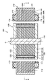
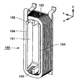
図1は、本発明の実施の形態1に係る回転電機の概略構成を示す側断面図である。図1に示すように、この回転電機100は、回転中心線Oを中心に回転可能に支持された回転シャフト110と、この回転シャフト110に固設され、回転シャフト110と共に回転可能に設けられたロータ120と、このロータ120の周囲に設けられた環状のステータ140とを備えている。この回転電機100は、典型的には、ハイブリッド車両に搭載され、車輪を駆動する駆動源や、エンジンなどの動力によって電気を発電する発電機として機能する。また、電気自動車などに搭載され、車輪を駆動する駆動源として利用される場合もある。
(Embodiment 1)
1 is a side sectional view showing a schematic configuration of a rotating electrical machine according to Embodiment 1 of the present invention. As shown in FIG. 1, the rotating
ロータ120は、複数の電磁鋼板などを積層して構成されたロータコア125と、ロータコア125に形成された磁石挿入孔126内に挿入された永久磁石123と、ロータコア125の軸方向の端面に設けられたエンドプレート122とを備えている。永久磁石123は、磁石挿入孔126内に充填された樹脂124によって接着固定されている。
The
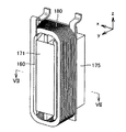
ステータ140は、環状に形成されており、ロータ120の周囲を取り囲むように環状に形成されたステータコア141と、このステータコア141の外周に装着されたリング181と、ステータコア141に装着されたU相コイル180U,V相コイル180V,W相コイル180Wとを備えている。ステータコア141は、複数の単位鋼板300が積層されて構成されている。ステータ140(ステータコア141)の軸方向端面177,178には、絶縁性のモールド樹脂172が形成されている。このモールド樹脂172は、たとえばBMC(Bulk Molding Compound)、エポキシ樹脂などの熱硬化性樹脂や、PPS(Polyphenylene Sulfide)、PBT(Polybutylene Terephthalate)などの熱可塑性樹脂などを含んでいる。
The
そして、ステータ140は、環状に延びるヨーク部本体170と、このヨーク部本体170の内周面から径方向内方に向けて突出する複数のステータティース171とを備えている。
The
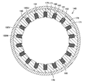
図2は、図1に示すII−II線に沿った、ステータの断面図である。図2に示すように、ステータ140は、複数の分割ステータコア175と、分割ステータコア175に装着されたインシュレータ160と、インシュレータ160を介在させて分割ステータコア175に装着されたコイル180と、環状に配列された分割ステータコア175の外周側に装着され、分割ステータコア175を固定するリング181とを備える。
FIG. 2 is a cross-sectional view of the stator taken along the line II-II shown in FIG. As shown in FIG. 2, the
ここで、各分割ステータコア175は、ステータ140の周方向に延びる円環状のヨーク部176と、このヨーク部176からステータ140の径方向内方に向けて突出するステータティース171とを備えている。ステータティース171は、ステータ140の円周方向に沿って等間隔に形成されている。
Here, each divided
ここで、ヨーク部176の表面のうち、ステータ140の周方向に配列する周方向端面190,191は、当該分割ステータコア175に対してステータ140の周方向に隣接する、他の分割ステータコア175の周方向端面190,191と、当接している。そして、各分割ステータコア175のヨーク部176が周方向に配列されることで、環状のヨーク部本体170が構成されている。
Here, among the surfaces of the
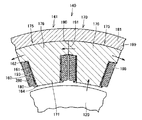
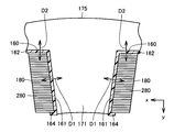
図3は、図2に示すステータの一部を拡大視した拡大断面図である。図3に示すように、隣り合うステータティース171間にはスロットが形成されており、スロット内には、ステータティース171に巻回されるコイル180が収容されている。コイル180は、このコイル180の延在方向に対して、垂直な断面形状が方形形状とされており、具体的には、エッジワイズコイル(Edge Width Coil)などの平角線が採用されている。このため、丸線を巻回して形成されるコイルと比較して、スロット内に収容されるコイル180の占積率(コイルの断面に占める導体の割合)の向上が図られており、またコイル180からの放熱性も優れている。
FIG. 3 is an enlarged cross-sectional view in which a part of the stator shown in FIG. 2 is enlarged. As shown in FIG. 3, a slot is formed between
このコイル180は、ステータティース171の表面のうち、ステータ140の周方向に配列する側面193に沿って順次積層するように、順次巻回されている。
The
そして、コイル180と分割ステータコア175との間には、絶縁性のインシュレータ160が設けられており、コイル180と分割ステータコア175との間の絶縁が確保されている。インシュレータ160は、コイル180と、ステータコア141に含まれる分割ステータコア175との間に存在して、コイル180を分割ステータコア175から絶縁する、絶縁部材である。
An
このインシュレータ160は、ステータティース171を受入れ可能な筒状のティース受入部161と、このティース受入部161の端部に形成され、ヨーク部176の内周面198に沿って延び、ヨーク部176の内周面198に支持される張出部162とを含む。ティース受入部161の周面のうち、回転中心線O側に位置する端部である軸方向端面には、回転中心線O方向に向けて突出する、フランジ部164が形成されている。
The
このように形成されたインシュレータ160には、コイル180が巻回されて装着されている。この図3に示すように、コイル180は、延在方向に対して垂直な断面の形状が、方形形状とされたコイル線280を巻回することで構成されている。インシュレータ160のティース受入部161は、巻回されたコイル180の内周と接する。インシュレータ160の張出部162は、巻回されたコイル180の側面と接する。
A
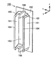
図4は、インシュレータの斜視図である。図4に示すように、インシュレータ160は、張出部162と、一対のティース受入部161と、一対の支柱部166とを含む。張出部162には開口部163が形成されており、この開口部163に対応するステータティース171(図2および図3参照)を通すことで、インシュレータ160がステータティース171に装着される。この張出部162は、インシュレータ160がステータティース171に装着されたとき、対応するコイル180(図2および図3参照)とスロット奥のヨーク部176の内周面198との間に配設され、コイル180をヨーク部176(図2および図3参照)から絶縁する。
FIG. 4 is a perspective view of the insulator. As shown in FIG. 4, the
ティース受入部161は、ステータティース171のスロット側の側面193を被覆可能なように、張出部162の開口部163の端部からステータコア141の内周方向(図4に示すy方向)に向かって延出される。すなわち、ティース受入部161は、インシュレータ160および対応するコイル180がステータティース171に装着されたとき、スロット内のコイル180をステータティース171と絶縁する。
The
また、ティース受入部161の回転中心線O側の先端部(y方向において張出部162から離れる側のティース受入部161の端部)には、フランジ部164が形成される。フランジ部164は、インシュレータ160に装着されたコイル180を積層方向(y方向)に支持可能に形成される。すなわち、フランジ部164は、インシュレータ160に装着されたコイル180がステータコア141の内周方向に巻崩れるのを防止する。
Further, a
さらに、ティース受入部161のz方向各端部には、側壁165が形成される。この側壁165は、ティース受入部161のz方向各端部において、コイル180とステータティース171との絶縁を確保するために形成される。
Further, a
支柱部166は、一対のティース受入部161間の略中央であってステータティース171のコイルエンド側端面に沿うように、張出部162の開口部163の端部からステータコア141の内周方向(y方向)に向かって延出される。すなわち、支柱部166は、ティース受入部161との間に空隙を有しつつ、ステータティース171のコイルエンド側端面に沿うように、張出部162から柱状に延出される。
The
そして、支柱部166は、インシュレータ160および対応するコイル180がステータティース171に装着されたとき、コイル180をz方向に支持するとともに、コイル180とステータティース171との絶縁距離を確保する。すなわち、支柱部166とティース受入部161との間には空隙が設けられるので、ステータティース171のコイルエンド側端面は、インシュレータ160によって全面が覆われないところ、コイル180をステータティース171と絶縁可能な距離に相当する厚み(z方向)を少なくとも有するように、支柱部166が形成される。
When the
図5は、インシュレータにコイルが装着された状態の斜視図である。図5に示すように、ティース受入部161を互いに対向する方向に屈撓させることにより、y方向からコイル180がインシュレータ160に装着される。そして、支柱部166によってコイル180がz方向に支持され、ティース受入部161の先端に設けられたフランジ部164によってコイル180が積層方向(y方向)に支持される。
FIG. 5 is a perspective view of a state where a coil is attached to the insulator. As shown in FIG. 5, the
図6は、インシュレータに装着されたコイルがステータティースに装着された状態の斜視図である。図6に示すように、インシュレータ160にコイル180が装着された後(図5参照)、コイル180およびインシュレータ160が一体的にステータティース171に装着される。
FIG. 6 is a perspective view of a state where a coil attached to an insulator is attached to a stator tooth. As shown in FIG. 6, after the
図7は、図6に示すVII−VII線に沿った、インシュレータにコイルが装着された状態の断面図である。図7に示すように、コイル180は、導体であるコイル線280がy方向に積層されるように巻回されており、インシュレータ160に設けられたフランジ部164によってコイル180の巻崩れが防止される。なお、コイル180としてエッジワイズコイルなどの平板導体が採用されている場合、コイル180の一部分のみをフランジ部164で支持するだけで、コイル180を支持することができる。コイル180が丸線や角線により形成される場合は、コイルの巻崩れを防止するためにフランジ部164のフランジ幅(x方向の長さ)を十分に確保しなければならないのに対し、コイル180が平角線であれば、フランジ部164のフランジ幅を小さくすることが可能である。
FIG. 7 is a cross-sectional view of a state where a coil is attached to the insulator along the line VII-VII shown in FIG. As shown in FIG. 7, the
図8は、図7に示すインシュレータの一部を拡大視した拡大断面図である。図8に示すように、インシュレータ160は、絶縁性を有する母材10と、母材10に混合された充填材(フィラー)20とを含む。充填材20は、母材10よりも熱伝導性の高い材料によって形成されている。母材10の材料は絶縁性を有する材料であればよく、たとえば、PA(Polyamide)、PBT(Polybutylene Terephthalate)、PPS(Polyphenilen Sulfide)、LCP(Liquid Crystal Polymer)などの樹脂材料を用いることができる。また充填材の材料は、母材10の材料に比較して熱伝導率の高い材料であればよく、たとえば、シリカ、アルミナ、フェライトに代表されるセラミックス材料などの、無機材料を用いることができる。
FIG. 8 is an enlarged cross-sectional view in which a part of the insulator shown in FIG. 7 is enlarged. As shown in FIG. 8, the
図8に示すように、充填材20は長手方向を有する。たとえば充填材20は繊維状の形状に形成されていてもよい。充填材20は、長手方向が母材10の厚み方向に沿うように向きが揃えられて、母材10に混合されている。インシュレータ160のティース受入部161および張出部162は、図4に示すように、板状の部材で形成されている。当該板状の部材は母材10と充填材20とを含み、充填材20の長手方向が板状の部材の厚み方向に沿うように、充填材20は配向されている。図7および図8に示す両矢印D1はティース受入部161の厚み方向であって、ティース受入部161に含まれる充填材20は、両矢印D1に示す方向に沿って配向されている。また両矢印D2は張出部162の厚み方向であって、張出部162に含まれる充填材20は、両矢印D2に示す方向に沿って配向されている。
As shown in FIG. 8, the
両矢印D1、D2に沿う方向とは、図7に示すように、コイル180から分割ステータコア175に向かう方向である。充填材20の長手方向は、コイル180から、ステータコア141に含まれる分割ステータコア175に向かう方向に沿うように、配向されている。
The direction along the double arrows D1 and D2 is a direction from the
長手方向を有する充填材20には、熱伝導の異方性が生じる。つまり、充填材20の方向によって熱の伝わり方が異なり、充填材20の長手方向への熱伝達量は、長手方向に直交する方向への熱伝達量に対して、より大きくなる。充填材20の長手方向に、熱はより伝わりやすくなっている。
The
充填材20の長手方向がコイル180からステータコア141に向かう方向に沿うように、充填材20を配向させて作製されたインシュレータ160では、コイル180からステータコア141へ向かう方向への熱伝導性が向上している。したがって、コイル180からステータコア141へ、インシュレータ160を介して効率よく放熱することができる。その結果、コイル180で発生した熱が外部へ効率よく放出されるので、コイル180を効率よく冷却することができる。
In the
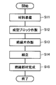
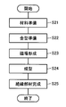
次に、インシュレータ160の製造方法について説明する。図9は、実施の形態1のインシュレータの製造方法を示す流れ図である。図9に示すように、まず工程(S11)において、インシュレータ160の材料を準備する。具体的には、母材10の材料として、たとえばPA、PBT、PPS、LCAなどの樹脂材料を準備する。また、充填材20の材料として、たとえばシリカ、アルミナ、フェライトなどのセラミックス材料を準備する。このとき充填材20の材料は、母材10の材料に比較して熱伝導率の高い材料とする。また充填材20の材料は、長手方向を有する形状に成形されている。
Next, a method for manufacturing the
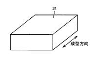
続いて工程(S12)において、成型ブロックを作製する。母材10の材料としてPA、PBT、PPS、LCAなどを用いる場合、これらは熱可塑性樹脂であるから、熱を加えると軟らかくなる。温度が上昇して溶融温度になると熱可塑性樹脂は溶けて流動し始め、さらに温度が上昇すると粘度が下がり、流れやすい流動体になる。このような熱可塑性樹脂の性質を利用して、成形が可能な温度まで上昇させ流動性を持った母材10の材料に充填材20の材料を混合させ、金型に押出し充填して、冷却して固める。このようにして、母材10および充填材20の材料を含む、直方体状の成型ブロックを作製することができる。図10は、成型ブロックの斜視図である。
Subsequently, in step (S12), a molding block is produced. When PA, PBT, PPS, LCA or the like is used as the material of the
このとき、充填材20の材料は長手方向を有する。そのため、母材10の材料が流動する流れ方向に、充填材20の材料の長手方向が沿うように、充填材20の材料が配向されて、成型ブロック31は作製される。たとえば図10に示す両矢印の方向が成型ブロック31の成型方向である場合、その成型方向に充填材20の長手方向が沿うように、成型ブロック31中に含まれる充填材20は配向されている。
At this time, the material of the
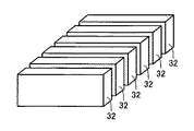
図9に戻って、続いて工程(S13)において、絶縁片を作製する。絶縁片とは、母材10と充填材20とを含む、板状に成形された部材である。母材10は絶縁性の材料であるから、絶縁片も絶縁性を有する。このような絶縁片は、工程(S12)で作製した成型ブロックをスライス切断する加工によって、得ることができる。
Returning to FIG. 9, subsequently, in step (S13), an insulating piece is produced. The insulating piece is a member formed into a plate shape including the
図11は、絶縁片を作製した状態を示す斜視図である。図10に示す成型ブロック31を、成型ブロック31の成型方向に直交する面を切断面として、スライス加工することによって、個々の絶縁片32を作製することができる。このようにして作製された絶縁片32では、板状の厚み方向に沿って、充填材20の長手方向が配向されている。
FIG. 11 is a perspective view showing a state in which an insulating piece is produced. The individual insulating
さらに、得られた絶縁片32を適宜加工して、ティース受入部161、張出部162およびフランジ部164の形状に成形する。
Further, the obtained insulating
図9に戻って、続いて工程(S14)において、インシュレータを組み立てる。たとえば、ティース受入部161、張出部162およびフランジ部164の形状に加工された絶縁片32を、たとえば絶縁片32の端部を加熱および冷却して、接合することによって、インシュレータ160を組み立て成形することができる。または、インシュレータ160の輪郭の形状を有するベース部材に、ティース受入部161、張出部162およびフランジ部164の形状に加工された絶縁片32を貼り付けることにより、インシュレータ160を組み立て成形することができる。
Returning to FIG. 9, the insulator is then assembled in step (S14). For example, the
このようにして、工程(S15)において、絶縁部材としてのインシュレータ160が完成する。インシュレータ160は、母材10と充填材20とを含む複数の絶縁片32を備えている。
Thus, the
図7および図8に示すインシュレータ160では、ティース受入部161および張出部162に含まれる充填材20の配向方向は、それぞれ両矢印D1およびD2に沿う方向であって異なる方向であるものの、板状の部材の厚み方向に沿う方向である点で共通している。そこで、以上説明したインシュレータ160の製造方法によると、成型ブロック31中に含まれる充填材20は、板状の絶縁片32へ加工されたとき絶縁片32の厚み方向となる一定方向(図10に両矢印で示す成型方向)に長手方向が沿うように、配向されている。
In the
よって、板状の絶縁片32の厚み方向に充填材20の長手方向が沿うように、充填材20を容易に配向させることができる。充填材20の配向方向の異なるティース受入部161と張出部162とを分割して製造することによって、充填材の長手方向がコイル180からステータコア141に向かう方向に沿うように配向されている、インシュレータ160を簡易に製造することができる。
Therefore, the
(実施の形態2)
図12は、実施の形態2のインシュレータの製造方法を示す流れ図である。実施の形態2のインシュレータ160は、図12に示すような製造方法によって製造される点で、実施の形態1とは異なっている。実施の形態2のインシュレータ160の製造方法について、図12に従って説明する。
(Embodiment 2)
FIG. 12 is a flowchart showing a method of manufacturing the insulator according to the second embodiment. The
具体的には、工程(S21)において、実施の形態1と同様にインシュレータ160の材料を準備する。このとき、充填材20としては、たとえば酸化鉄を主成分とするセラミックス材料であるフェライトなどの、強磁性体を有する材料を準備する。
Specifically, in the step (S21), a material for the
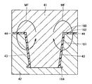
続いて工程(S22)において、金型を準備する。図13は、金型の断面模式図である。図13に示すように、金型は、上金型41と下金型42とを含む。図13に示す上金型41と下金型42とを組み合わせた状態において、上金型41と下金型42との間には隙間43が形成されている。また、隙間43を外部と連通する開口部44が、上金型41と下金型42との間に形成されている。
Subsequently, in step (S22), a mold is prepared. FIG. 13 is a schematic cross-sectional view of a mold. As shown in FIG. 13, the mold includes an
続いて工程(S23)において、金型を含む空間に磁場を印加する。図13中の矢印は、磁場MFの形成されている方向を示す。続いて工程(S24)において、インシュレータ160を成型する。たとえば熱可塑性樹脂である母材10の材料を加熱して流動可能な状態とし、その流動体を開口部44から隙間43に注入して、冷却することにより、ティース受入部161、張出部162部およびフランジ部164を有する、インシュレータ160を形成する。
Subsequently, in step (S23), a magnetic field is applied to the space including the mold. The arrows in FIG. 13 indicate the direction in which the magnetic field MF is formed. Subsequently, in step (S24), the
このとき、金型を含む空間には磁場MFが印加されており、磁場MF中でインシュレータ160が成型されているために、強磁性体の充填材20は磁場MFの方向に配向する。長手方向を有する充填材20では、図13中の矢印で示す磁場MFの方向に長手方向が沿うように、充填材20は配向される。つまり、充填材20の長手方向が、ティース受入部161および張出部162のいずれに対しても厚み方向に沿うように、インシュレータ160は成型されている。このようにして、工程(S25)において、絶縁部材としてのインシュレータ160が完成する。
At this time, since the magnetic field MF is applied to the space including the mold and the
一般的に、樹脂を成型する際には、金型中で樹脂が流れる方向に充填材の長手方向が沿うように、充填材は配向されやすいという特徴がある。そのため、図13に示す金型を用いて樹脂を成型する場合、通常は板状部材の厚み方向に充填材の長手方向を配向させるのは困難である。しかし、実施の形態2のインシュレータ160の製造方法によると、磁場MFをかけて磁場中でインシュレータ160を成型させることにより、強磁性体を有する充填材20は、板状のティース受入部161および張出部162の厚み方向に長手方向が沿うように、配向される。したがって、実施の形態1と同様に、充填材の長手方向がコイル180からステータコア141に向かう方向に沿うように配向されている、インシュレータ160を簡易に製造することができる。
In general, when molding a resin, there is a feature that the filler is easily oriented so that the longitudinal direction of the filler is along the direction in which the resin flows in the mold. Therefore, when resin is molded using the mold shown in FIG. 13, it is usually difficult to orient the longitudinal direction of the filler in the thickness direction of the plate member. However, according to the method for manufacturing the
今回開示された実施の形態はすべての点で例示であって、制限的なものではないと考えられるべきである。この発明の範囲は上記した説明ではなくて特許請求の範囲によって示され、特許請求の範囲と均等の意味、および範囲内でのすべての変更が含まれることが意図される。 The embodiment disclosed this time is to be considered as illustrative in all points and not restrictive. The scope of the present invention is defined by the terms of the claims, rather than the description above, and is intended to include any modifications within the scope and meaning equivalent to the terms of the claims.
本発明の絶縁部材は、車両に搭載される回転電機においてコイルをステータコアから絶縁する絶縁部材に、特に有利に適用され得る。 The insulating member of the present invention can be particularly advantageously applied to an insulating member that insulates a coil from a stator core in a rotating electrical machine mounted on a vehicle.
10 母材、20 充填材、31 成型ブロック、32 絶縁片、41 上金型、42 下金型、43 隙間、44 開口部、100 回転電機、110 回転シャフト、120 ロータ、122 エンドプレート、123 永久磁石、124 樹脂、125 ロータコア、126 磁石挿入孔、140 ステータ、141 ステータコア、160 インシュレータ、161 ティース受入部、162 張出部、163 開口部、164 フランジ部、165 側壁、166 支柱部、170 ヨーク部本体、171 ステータティース、172 モールド樹脂、175 分割ステータコア、176 ヨーク部、177,178 軸方向端面、180 コイル、181 リング、190,191 周方向端面、193 側面、198 内周面、280 コイル線。 10 base material, 20 filler, 31 molding block, 32 insulating piece, 41 upper mold, 42 lower mold, 43 gap, 44 opening, 100 rotating electrical machine, 110 rotating shaft, 120 rotor, 122 end plate, 123 permanent Magnet, 124 Resin, 125 Rotor core, 126 Magnet insertion hole, 140 Stator, 141 Stator core, 160 Insulator, 161 Teeth receiving part, 162 Overhang part, 163 Opening part, 164 Flange part, 165 Side wall, 166 Post part, 170 Yoke part Main body, 171 stator teeth, 172 mold resin, 175 divided stator core, 176 yoke portion, 177,178 axial end face, 180 coil, 181 ring, 190,191 circumferential end face, 193 side face, 198 inner peripheral face, 280 coil wire.
Claims (4)
絶縁性を有する母材と、
前記母材に混合された、前記母材よりも熱伝導性の高い充填材とを含み、
前記充填材は長手方向を有し、
前記長手方向が前記コイルから前記ステータコアに向かう方向に沿うように、前記充填材が配向されている、絶縁部材。 An insulating member that exists between the coil and the stator core and insulates the coil from the stator core;
An insulating base material;
Including a filler mixed with the base material and having higher thermal conductivity than the base material,
The filler has a longitudinal direction;
An insulating member in which the filler is oriented so that the longitudinal direction is along the direction from the coil toward the stator core.
前記絶縁片は、成型ブロックを加工して板状に形成されており、
前記成型ブロック中に含まれる前記充填材は、前記絶縁片の厚み方向となる一定方向に前記長手方向が沿うように配向されている、請求項2に記載の絶縁部材。 The insulating member includes a plurality of insulating pieces including the base material and the filler.
The insulating piece is formed into a plate by processing a molding block,
The insulating member according to claim 2, wherein the filler contained in the molding block is oriented so that the longitudinal direction is along a certain direction that is a thickness direction of the insulating piece.
磁場中で前記絶縁部材を成型することにより、前記充填材の長手方向は磁場の方向に配向されている、請求項1または請求項2に記載の絶縁部材。 The filler is a ferromagnetic material,
The insulating member according to claim 1 or 2, wherein the longitudinal direction of the filler is oriented in the direction of the magnetic field by molding the insulating member in a magnetic field.
Priority Applications (1)
| Application Number | Priority Date | Filing Date | Title |
|---|---|---|---|
| JP2008313443A JP2010141960A (en) | 2008-12-09 | 2008-12-09 | Insulating member |
Applications Claiming Priority (1)
| Application Number | Priority Date | Filing Date | Title |
|---|---|---|---|
| JP2008313443A JP2010141960A (en) | 2008-12-09 | 2008-12-09 | Insulating member |
Publications (1)
| Publication Number | Publication Date |
|---|---|
| JP2010141960A true JP2010141960A (en) | 2010-06-24 |
Family
ID=42351585
Family Applications (1)
| Application Number | Title | Priority Date | Filing Date |
|---|---|---|---|
| JP2008313443A Pending JP2010141960A (en) | 2008-12-09 | 2008-12-09 | Insulating member |
Country Status (1)
| Country | Link |
|---|---|
| JP (1) | JP2010141960A (en) |
Cited By (5)
| Publication number | Priority date | Publication date | Assignee | Title |
|---|---|---|---|---|
| WO2013125676A1 (en) * | 2012-02-24 | 2013-08-29 | 日産自動車株式会社 | Stator |
| JP2015035879A (en) * | 2013-08-08 | 2015-02-19 | トヨタ自動車株式会社 | Coil holding member of electronic apparatus |
| JP2015139269A (en) * | 2014-01-22 | 2015-07-30 | トヨタ自動車株式会社 | Stator |
| JP2016142251A (en) * | 2015-02-05 | 2016-08-08 | マツダ株式会社 | Heat conductive member used in engine, and engine structure including the same |
| WO2021210241A1 (en) * | 2020-04-14 | 2021-10-21 | 日立Astemo株式会社 | Insulating adhesive member for coil, and electrical device |
Citations (4)
| Publication number | Priority date | Publication date | Assignee | Title |
|---|---|---|---|---|
| JPS5941071U (en) * | 1982-09-07 | 1984-03-16 | 三菱電機株式会社 | rotating electric machine |
| JPH07227053A (en) * | 1994-02-08 | 1995-08-22 | Toshiba Corp | Magnetic wedge of rotating electric machine and method of manufacturing the same |
| JPH1094205A (en) * | 1996-09-13 | 1998-04-10 | Toshiba Corp | Rotating electric machine |
| JP2008108756A (en) * | 2006-10-23 | 2008-05-08 | Nissan Motor Co Ltd | Insulating material, motor stator manufacturing method using insulating material, and insulating material assembling method for semiconductor device |
-
2008
- 2008-12-09 JP JP2008313443A patent/JP2010141960A/en active Pending
Patent Citations (4)
| Publication number | Priority date | Publication date | Assignee | Title |
|---|---|---|---|---|
| JPS5941071U (en) * | 1982-09-07 | 1984-03-16 | 三菱電機株式会社 | rotating electric machine |
| JPH07227053A (en) * | 1994-02-08 | 1995-08-22 | Toshiba Corp | Magnetic wedge of rotating electric machine and method of manufacturing the same |
| JPH1094205A (en) * | 1996-09-13 | 1998-04-10 | Toshiba Corp | Rotating electric machine |
| JP2008108756A (en) * | 2006-10-23 | 2008-05-08 | Nissan Motor Co Ltd | Insulating material, motor stator manufacturing method using insulating material, and insulating material assembling method for semiconductor device |
Cited By (5)
| Publication number | Priority date | Publication date | Assignee | Title |
|---|---|---|---|---|
| WO2013125676A1 (en) * | 2012-02-24 | 2013-08-29 | 日産自動車株式会社 | Stator |
| JP2015035879A (en) * | 2013-08-08 | 2015-02-19 | トヨタ自動車株式会社 | Coil holding member of electronic apparatus |
| JP2015139269A (en) * | 2014-01-22 | 2015-07-30 | トヨタ自動車株式会社 | Stator |
| JP2016142251A (en) * | 2015-02-05 | 2016-08-08 | マツダ株式会社 | Heat conductive member used in engine, and engine structure including the same |
| WO2021210241A1 (en) * | 2020-04-14 | 2021-10-21 | 日立Astemo株式会社 | Insulating adhesive member for coil, and electrical device |
Similar Documents
| Publication | Publication Date | Title |
|---|---|---|
| JP6373854B2 (en) | Stator or rotor | |
| JP5567311B2 (en) | Axial gap motor, compressor, motor system, and generator | |
| CN104170212B (en) | motor | |
| JP5533285B2 (en) | Insulating member and stator manufacturing method | |
| TWI583109B (en) | Axial air gap type rotary motor and rotary tube with rotating electrical machine | |
| US9184638B2 (en) | Stator structure and stator manufacturing method | |
| JP5731338B2 (en) | Rotating electric machine | |
| JP5916591B2 (en) | Axial gap motor | |
| CN204633497U (en) | Coil, rotary and linear motors | |
| US11047603B2 (en) | Rotor, motor, and air conditioning apparatus | |
| JP2003284277A (en) | Rotating electric machine and method of manufacturing the same | |
| JP5569289B2 (en) | Rotating electric machine stator | |
| CN102246393A (en) | Stator and method of manufacturing stator | |
| JP2010141960A (en) | Insulating member | |
| JP7109658B2 (en) | Stator, motor, blower, air conditioner, and stator manufacturing method | |
| JP6818900B2 (en) | Manufacturing method of stator and stator of rotary electric machine | |
| US20240204602A1 (en) | Rotary electric machine | |
| JP2018143048A (en) | Method for molding resin casing and motor | |
| JP2018143049A (en) | Motor manufacturing method and motor | |
| JP2015027175A (en) | Rotating electrical machine and method of manufacturing rotating electrical machine | |
| JP5991011B2 (en) | Motor stator structure and manufacturing method thereof | |
| CN103683594B (en) | Electric rotating machine | |
| JPH06327208A (en) | DC brushless motor stator | |
| JP6876692B2 (en) | Rotating machine | |
| JP2011045197A (en) | Permanent magnet type rotary electric machine and manufacturing method of the same |
Legal Events
| Date | Code | Title | Description |
|---|---|---|---|
| A621 | Written request for application examination |
Free format text: JAPANESE INTERMEDIATE CODE: A621 Effective date: 20110613 |
|
| A977 | Report on retrieval |
Free format text: JAPANESE INTERMEDIATE CODE: A971007 Effective date: 20121212 |
|
| A131 | Notification of reasons for refusal |
Free format text: JAPANESE INTERMEDIATE CODE: A131 Effective date: 20121218 |
|
| A02 | Decision of refusal |
Free format text: JAPANESE INTERMEDIATE CODE: A02 Effective date: 20130507 |