EP3505736A1 - Air guide structure of vehicle - Google Patents
Air guide structure of vehicle Download PDFInfo
- Publication number
- EP3505736A1 EP3505736A1 EP18201765.7A EP18201765A EP3505736A1 EP 3505736 A1 EP3505736 A1 EP 3505736A1 EP 18201765 A EP18201765 A EP 18201765A EP 3505736 A1 EP3505736 A1 EP 3505736A1
- Authority
- EP
- European Patent Office
- Prior art keywords
- duct
- variable screen
- air guide
- guide structure
- screen
- Prior art date
- Legal status (The legal status is an assumption and is not a legal conclusion. Google has not performed a legal analysis and makes no representation as to the accuracy of the status listed.)
- Granted
Links
Images








Classifications
-
- B—PERFORMING OPERATIONS; TRANSPORTING
- B60—VEHICLES IN GENERAL
- B60K—ARRANGEMENT OR MOUNTING OF PROPULSION UNITS OR OF TRANSMISSIONS IN VEHICLES; ARRANGEMENT OR MOUNTING OF PLURAL DIVERSE PRIME-MOVERS IN VEHICLES; AUXILIARY DRIVES FOR VEHICLES; INSTRUMENTATION OR DASHBOARDS FOR VEHICLES; ARRANGEMENTS IN CONNECTION WITH COOLING, AIR INTAKE, GAS EXHAUST OR FUEL SUPPLY OF PROPULSION UNITS IN VEHICLES
- B60K11/00—Arrangement in connection with cooling of propulsion units
- B60K11/06—Arrangement in connection with cooling of propulsion units with air cooling
-
- B—PERFORMING OPERATIONS; TRANSPORTING
- B60—VEHICLES IN GENERAL
- B60K—ARRANGEMENT OR MOUNTING OF PROPULSION UNITS OR OF TRANSMISSIONS IN VEHICLES; ARRANGEMENT OR MOUNTING OF PLURAL DIVERSE PRIME-MOVERS IN VEHICLES; AUXILIARY DRIVES FOR VEHICLES; INSTRUMENTATION OR DASHBOARDS FOR VEHICLES; ARRANGEMENTS IN CONNECTION WITH COOLING, AIR INTAKE, GAS EXHAUST OR FUEL SUPPLY OF PROPULSION UNITS IN VEHICLES
- B60K11/00—Arrangement in connection with cooling of propulsion units
- B60K11/08—Air inlets for cooling; Shutters or blinds therefor
-
- F—MECHANICAL ENGINEERING; LIGHTING; HEATING; WEAPONS; BLASTING
- F02—COMBUSTION ENGINES; HOT-GAS OR COMBUSTION-PRODUCT ENGINE PLANTS
- F02B—INTERNAL-COMBUSTION PISTON ENGINES; COMBUSTION ENGINES IN GENERAL
- F02B29/00—Engines characterised by provision for charging or scavenging not provided for in groups F02B25/00, F02B27/00 or F02B33/00 - F02B39/00; Details thereof
- F02B29/04—Cooling of air intake supply
- F02B29/0406—Layout of the intake air cooling or coolant circuit
- F02B29/0425—Air cooled heat exchangers
- F02B29/0431—Details or means to guide the ambient air to the heat exchanger, e.g. having a fan, flaps, a bypass or a special location in the engine compartment
-
- B—PERFORMING OPERATIONS; TRANSPORTING
- B60—VEHICLES IN GENERAL
- B60K—ARRANGEMENT OR MOUNTING OF PROPULSION UNITS OR OF TRANSMISSIONS IN VEHICLES; ARRANGEMENT OR MOUNTING OF PLURAL DIVERSE PRIME-MOVERS IN VEHICLES; AUXILIARY DRIVES FOR VEHICLES; INSTRUMENTATION OR DASHBOARDS FOR VEHICLES; ARRANGEMENTS IN CONNECTION WITH COOLING, AIR INTAKE, GAS EXHAUST OR FUEL SUPPLY OF PROPULSION UNITS IN VEHICLES
- B60K11/00—Arrangement in connection with cooling of propulsion units
- B60K11/02—Arrangement in connection with cooling of propulsion units with liquid cooling
- B60K11/04—Arrangement or mounting of radiators, radiator shutters, or radiator blinds
-
- B—PERFORMING OPERATIONS; TRANSPORTING
- B60—VEHICLES IN GENERAL
- B60K—ARRANGEMENT OR MOUNTING OF PROPULSION UNITS OR OF TRANSMISSIONS IN VEHICLES; ARRANGEMENT OR MOUNTING OF PLURAL DIVERSE PRIME-MOVERS IN VEHICLES; AUXILIARY DRIVES FOR VEHICLES; INSTRUMENTATION OR DASHBOARDS FOR VEHICLES; ARRANGEMENTS IN CONNECTION WITH COOLING, AIR INTAKE, GAS EXHAUST OR FUEL SUPPLY OF PROPULSION UNITS IN VEHICLES
- B60K11/00—Arrangement in connection with cooling of propulsion units
- B60K11/08—Air inlets for cooling; Shutters or blinds therefor
- B60K11/085—Air inlets for cooling; Shutters or blinds therefor with adjustable shutters or blinds
-
- B—PERFORMING OPERATIONS; TRANSPORTING
- B60—VEHICLES IN GENERAL
- B60K—ARRANGEMENT OR MOUNTING OF PROPULSION UNITS OR OF TRANSMISSIONS IN VEHICLES; ARRANGEMENT OR MOUNTING OF PLURAL DIVERSE PRIME-MOVERS IN VEHICLES; AUXILIARY DRIVES FOR VEHICLES; INSTRUMENTATION OR DASHBOARDS FOR VEHICLES; ARRANGEMENTS IN CONNECTION WITH COOLING, AIR INTAKE, GAS EXHAUST OR FUEL SUPPLY OF PROPULSION UNITS IN VEHICLES
- B60K13/00—Arrangement in connection with combustion air intake or gas exhaust of propulsion units
- B60K13/02—Arrangement in connection with combustion air intake or gas exhaust of propulsion units concerning intake
-
- F—MECHANICAL ENGINEERING; LIGHTING; HEATING; WEAPONS; BLASTING
- F02—COMBUSTION ENGINES; HOT-GAS OR COMBUSTION-PRODUCT ENGINE PLANTS
- F02B—INTERNAL-COMBUSTION PISTON ENGINES; COMBUSTION ENGINES IN GENERAL
- F02B29/00—Engines characterised by provision for charging or scavenging not provided for in groups F02B25/00, F02B27/00 or F02B33/00 - F02B39/00; Details thereof
- F02B29/04—Cooling of air intake supply
-
- B—PERFORMING OPERATIONS; TRANSPORTING
- B60—VEHICLES IN GENERAL
- B60Y—INDEXING SCHEME RELATING TO ASPECTS CROSS-CUTTING VEHICLE TECHNOLOGY
- B60Y2306/00—Other features of vehicle sub-units
- B60Y2306/05—Cooling
-
- Y—GENERAL TAGGING OF NEW TECHNOLOGICAL DEVELOPMENTS; GENERAL TAGGING OF CROSS-SECTIONAL TECHNOLOGIES SPANNING OVER SEVERAL SECTIONS OF THE IPC; TECHNICAL SUBJECTS COVERED BY FORMER USPC CROSS-REFERENCE ART COLLECTIONS [XRACs] AND DIGESTS
- Y02—TECHNOLOGIES OR APPLICATIONS FOR MITIGATION OR ADAPTATION AGAINST CLIMATE CHANGE
- Y02T—CLIMATE CHANGE MITIGATION TECHNOLOGIES RELATED TO TRANSPORTATION
- Y02T10/00—Road transport of goods or passengers
- Y02T10/10—Internal combustion engine [ICE] based vehicles
- Y02T10/12—Improving ICE efficiencies
Definitions
- the present invention relates to an air guide structure of a vehicle, and more particularly, to an intercooler air guide structure of a turbo engine vehicle.
- flow rates of a flow A of outdoor air introduced through the radiator grille 1 and a flow B of outdoor air introduced through the bumper grille 2 are different based on designs of the radiator grille 1 and the bumper grille 2 of each vehicle, and even in the case of the same design, a difference in flow rate occurs based on a vehicle speed.
- the duct type air guide 3 in which the fixed screen 33 is installed may not reflect the difference in the flow rate, thus a flow at a front surface portion of the intercooler in the duct may not be smoothly formed, which results in decrease in cooling efficiency of the intercooler, thereby decreasing torque of the engine and fuel efficiency.
- An aspect of the present invention provides an air guide structure of a vehicle capable of maximizing cooling performance of an intercooler by installing a variable screen of which a shape or a position may be changed based on a pressure difference resulting from a difference in flow rate between an upper flow and a lower flow introduced through a duct.
- the air guide structure may include: a variable screen positioned between the upper duct and the lower duct and formed to have a shape or a position changed based on a difference in flow rate between upper flow and lower flow introduced through the upper duct and the lower duct, respectively.
- the variable screen may be disposed on a duct wall surface between the upper duct and the lower duct.
- variable screen may be formed of a material having elasticity to allow the shape of the variable screen to be changed.
- the material having elasticity may be a rubber material.
- the shape of the variable screen may be changed based on the difference in flow rate between the upper duct and the lower duct occurring based on a vehicle speed of the vehicle to deform the variable screen toward a duct of which a flow rate is less than the other to decrease a pressure difference resulting from the difference in flow rate.
- a pressure adjustment aperture may be formed in the variable screen to adjust an amount of deformation of the variable screen according to the difference in flow rate.
- the variable screen may be fixedly coupled to the duct wall surface between the upper duct and the lower duct by bonding or fusion.
- the variable screen may be fixedly coupled to the duct wall surface between the upper duct and the lower duct by rivet connection.
- a flange part for connecting one side portion of the variable screen using a rivet may be formed on the duct wall surface between the upper duct and the lower duct.
- the variable screen may be fixedly coupled to the duct wall surface between the upper duct and the lower duct by forcible fitting.
- a flange part that connects the variable screen may be formed on the duct wall surface between the upper duct and the lower duct, a forcible fitting groove may be formed in the flange part, and a forcible fitting protrusion may be formed at one side surface of the variable screen, the forcible fitting protrusion being forcibly fitted into the forcible fitting groove of the flange part.
- the variable screen may be fixedly coupled to the duct wall surface between the upper duct and the lower duct by casing. Additionally, a screen holder may be attached on one side surface of the variable screen and a coupling aperture in which the screen holder is fixedly coupled may be formed in the duct wall surface between the upper duct and the lower duct. When the variable screen is inserted into the duct while passing through the coupling aperture, the screen holder may be fitted in the coupling aperture, to fixedly couple the variable screen to the duct wall surface between the upper duct and the lower duct.
- the position of the variable screen may be changed vertically between the upper duct and the lower duct.
- the position of the variable screen may be moved according to the difference in flow rate between the upper duct and the lower duct occurring based on a vehicle speed of the vehicle and thus, the variable screen may be moved toward a duct of which a flow rate is less than the other to decrease a pressure difference resulting from the difference in flow rate.
- a pressure adjustment aperture may be formed in the variable screen to adjust an amount of vertical movement of the variable screen according to the difference in flow rate.
- An upper frame and a lower frame may be fixedly installed on the duct wall surface between the upper duct and the lower duct while being vertically spaced apart from each other, and a vertical movement guide that guides the variable screen to move vertically may be installed between the upper frame and the lower frame.
- a guide aperture through which the vertical movement guide passes may be formed in the variable screen, to allow the variable screen to be slidably coupled to the vertical movement guide.
- vehicle or “vehicular” or other similar term as used herein is inclusive of motor vehicles in general such as passenger automobiles including sports utility vehicles (SUV), buses, trucks, various commercial vehicles, watercraft including a variety of boats and ships, aircraft, and the like, and includes hybrid vehicles, electric vehicles, combustion, plug-in hybrid electric vehicles, hydrogen-powered vehicles and other alternative fuel vehicles (e.g. fuels derived from resources other than petroleum).
- motor vehicles in general such as passenger automobiles including sports utility vehicles (SUV), buses, trucks, various commercial vehicles, watercraft including a variety of boats and ships, aircraft, and the like, and includes hybrid vehicles, electric vehicles, combustion, plug-in hybrid electric vehicles, hydrogen-powered vehicles and other alternative fuel vehicles (e.g. fuels derived from resources other than petroleum).
- SUV sports utility vehicles
- plug-in hybrid electric vehicles e.g. fuels derived from resources other than petroleum
- FIG. 5 is a cross-sectional view illustrating a duct type air guide in which a variable screen is installed according to an exemplary embodiment of the present invention.
- a screen e.g., partition wall
- a radiator grille inlet duct e.g., upper duct
- a bumper grille inlet duct e.g., lower duct
- the variable screen 33' or 33" may be formed so that a shape or a position thereof may be changed, and each embodiment will be described below in detail.
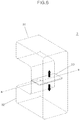
- FIG. 6 is a perspective view illustrating an inside of a duct type air guide in which a variable screen is installed according to a first exemplary embodiment of the present invention.
- a position of the variable screen 33' according to a first exemplary embodiment of the present invention may be fixed between the radiator grille inlet duct 31 and the bumper grille inlet duct 32 as in the related art, however, since a flexible material is used for the variable screen 33', a shape of the variable screen 33' may be changed according to a pressure difference between the upper flow and the lower flow introduced through the ducts 31 and 32.
- the flexible material is a material having elasticity and may be a rubber material.
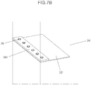
- FIGS. 7A to 7D are views illustrating a duct coupling structure of the variable screen according to the first exemplary embodiment of the present invention.
- the variable screen 33' according to the first exemplary embodiment of the present invention may be fixed to a duct wall surface 34 between the radiator grille inlet duct 31 and the bumper grille inlet duct 32, and may be fixed by various coupling methods such as bonding or fusion, rivet connection, forcible fitting, casing, and the like.
- variable screen 33' when the variable screen 33' is fixedly coupled by bonding or fusion, a portion of a side surface of the variable screen 33' contacting the duct wall surface 34 is entirely or partially bonded or fused on the duct wall surface 34, and thus, the variable screen 33' is fixedly coupled to the duct wall surface 34 between the radiator grille inlet duct 31 and the bumper grille inlet duct 32.
- FIG. 7B when the variable screen 33' is fixedly coupled by rivet connection, a flange part 341 for connecting the variable screen 33' is formed on the duct wall surface 34.
- variable screen 33' The flange part 341 and one side portion of the variable screen 33' vertically overlap each other, and a rivet 36 is driven, to fixedly couple the variable screen 33' to the duct wall surface 34 between the radiator grille inlet duct 31 and the bumper grille inlet duct 32.
- variable screen 33' when the variable screen 33' is fixedly coupled by forcible fitting, a flange part 341 for connecting the variable screen 33' is formed on the duct wall surface 34, a forcible fitting groove 342 is formed in the flange part 342, a forcible fitting protrusion 331 is formed at one side surface of the variable screen 33', and the forcible fitting protrusion 331 of the variable screen 33' is forcibly fitted into the forcible fitting groove 342 of the flange part 341. Accordingly, the variable screen 33' is fixedly coupled to the duct wall surface 34 between the radiator grille inlet duct 31 and the bumper grille inlet duct 32.
- variable screen 33' when the variable screen 33' is fixedly coupled by casing, a screen holder 332 is attached on one side surface of the variable screen 33', a coupling aperture 343 in which the screen holder 332 is fixedly coupled is formed in the duct wall surface 34.
- the screen holder 332 When the variable screen 33' is inserted into the duct while passing through the coupling aperture 343, the screen holder 332 may be fitted in the coupling aperture 343, to fixedly couple the variable screen 33' to the duct wall surface 34 between the radiator grille inlet duct 31 and the bumper grille inlet duct 32.
- FIGS. 8A to 8C are views illustrating an operation scheme of the variable screen according to the first exemplary embodiment of the present invention.
- the shape of the variable screen 33' according to the first exemplary embodiment of the present invention may be changed according to the difference in flow rate between the two ducts 31 and 32 based on a vehicle speed of the vehicle.
- the variable screen 33' may be deformed toward a duct of which the flow rate is less than the other, thereby decreasing a pressure difference resulting from the difference in flow rate.
- variable screen when the vehicle travels at high speed and the flow rate of the lower duct 32 is increased, the variable screen may be deformed toward the upper duct 31 (see FIG. 8A ). When the flow rate of the upper duct 31 is increased, the variable screen may be deformed toward the lower duct 32 (see FIG. 8B ). Additionally, when the vehicle is stopped or travels at low speed, since a pressure difference does not occur, the variable screen 33 may not be deformed (see FIG. 8C ). Accordingly, flow rate distribution at a front surface of the intercooler may be performed more efficiently, and as a result, a flow rate of flow passing through the intercooler is increased, thereby improving cooling performance.
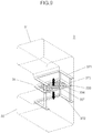
- FIG. 9 is a perspective view illustrating an inside of a duct type air guide in which a variable screen is installed according to a second exemplary embodiment of the present invention.
- a variable screen 33" according to a second exemplary embodiment of the present invention is formed so that a position thereof may be vertically changed between the radiator grille inlet duct 31 and the bumper grille inlet duct 32.
- an upper frame 371 and a lower frame 372 may be fixedly installed on the duct wall surface 34 between the ducts 31 and 32 while being vertically spaced apart from each other, and a vertical movement guide 373 that guides the variable screen 33" to move vertically may be installed between the upper frame 371 and the lower frame 372.
- a guide aperture 333 through which the vertical movement guide 373 passes may be formed in the variable screen 33" to slidably couple the variable screen 33" to the vertical movement guide 373.
- a pressure adjustment aperture 334 may be formed in the variable screen 33" according to the second exemplary embodiment of the present disclosure to adjust an amount of vertical movement of the variable screen 33" based on a pressure difference. Such a pressure adjustment aperture 334 may also be applied to the variable screen 33' according to the first exemplary embodiment of the present invention.
- FIGS. 10A to 10C are views illustrating an operation scheme of the variable screen according to the second exemplary embodiment of the present invention.
- a position of the variable screen 33" according to the second exemplary embodiment of the present invention may be moved according to a difference in flow rate between the two ducts 31 and 32 occurring based on a vehicle speed of the vehicle to move the position of the variable screen 33" toward a duct of which the flow rate is less than the other (e.g., a duct among a plurality of ducts having a lower flow rate than the remaining ducts), thereby decreasing a pressure difference resulting from the difference in flow rate.
- variable screen 33" moves toward the upper duct 31 (see FIG. 10A ).
- the variable screen 33" may be positioned in the middle between the upper duct 31 and the lower duct 32 (see FIG. 10B ).
- the variable screen 33" moves toward the lower duct 32 due to the weight of the screen (see FIG. 10C ). Accordingly, flow rate distribution at a front surface of the intercooler may be performed more efficiently, and as a result, a flow rate of flow passing through the intercooler is increased, thereby improving cooling performance.
- Table 1 shows result data obtained by performing computational fluid dynamics analysis with respect to a volume of air passing through the intercooler at each vehicle speed, through comparison between a duct type air guide (Comparative Example 1) without a screen and a duct type air guide (Comparative Example 2) in which the fixed screen 33 is installed to verify an effect of the duct type air guide in which the variable screen 33' or 33" according to the present invention is installed.
- the air guide structure of a vehicle may achieve the effect of improving cooling performance of the intercooler without increasing weight and costs. Additionally, as the cooling performance is improved, a temperature of supercharged air is decreased, such that power performance and fuel efficiency of the engine may be improved.
Landscapes
- Engineering & Computer Science (AREA)
- Chemical & Material Sciences (AREA)
- Combustion & Propulsion (AREA)
- Mechanical Engineering (AREA)
- Transportation (AREA)
- Physics & Mathematics (AREA)
- Thermal Sciences (AREA)
- General Engineering & Computer Science (AREA)
- Cooling, Air Intake And Gas Exhaust, And Fuel Tank Arrangements In Propulsion Units (AREA)
Abstract
Description
- This application claims priority to Korean Patent Application No.
10-2017-0183528, filed on December 29, 2017 - The present invention relates to an air guide structure of a vehicle, and more particularly, to an intercooler air guide structure of a turbo engine vehicle.
-
-
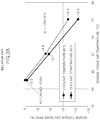
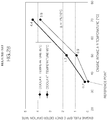
FIG. 1 is a schematic view of a turbo engine system according to the related art, andFIGS. 2A and2B are graphs illustrating influence of a temperature of supercharged air on engine torque and fuel efficiency of the turbo engine system according to the related art. Referring toFIG. 1 , a turbo engine cools high temperature supercharged air compressed through aturbo charger 10 by passing the supercharged air through anintercooler 30 before supplying the supercharged air to anengine 20. As illustrated inFIGS. 2A and2B , a temperature of the supercharged air supplied to theengine 20 significantly affects torque and fuel efficiency of theengine 20, and generally, as the temperature of the supercharged air is decreased, the torque of theengine 20 is increased, and the fuel efficiency is improved. Therefore, in the turbo engine, increasing cooling efficiency of theintercooler 30 is an important factor in improving power and fuel efficiency. -
FIG. 3 is a view illustrating a duct type air guide of a side by side (SBS) type installed at a side surface portion of a radiator grille and a bumper grille of a vehicle according to the related art. Referring toFIG. 3 , theintercooler 30 cools high temperature supercharged air supplied from theturbo charger 30 by outdoor air supplied from a radiator grille 1 and abumper grille 2 while the vehicle is being driven. Accordingly, the ducttype air guide 3 of the SBS type is installed at a side surface portion of the radiator grille 1 and thebumper grille 2 of the vehicle. The ducttype air guide 3 of the SBS type includes a radiatorgrille inlet duct 31 disposed in the radiator grille 1 and a bumpergrille inlet duct 32 disposed in thebumper grille 2 as ducts into which outdoor air is introduced. -
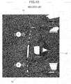
FIG. 4A is a cross-sectional view illustrating a duct type air guide in which a fixed screen is installed according to the related art, andFIG. 4B is a view illustrating a flow field in the duct type air guide illustrated inFIG. 4A according to the related art. Referring toFIG. 4A , in the ducttype air guide 3 according to the related art, a fixed screen (e.g., partition wall) 33 of which a shape and a position are fixed is installed between the radiatorgrille inlet duct 31 and the bumpergrille inlet duct 32 that are vertically disposed to divide an area of heat exchange of theintercooler 30 by outdoor air introduced through the respective ducts at a ratio of 1:1. - However, referring to
FIG. 4B , flow rates of a flow A of outdoor air introduced through the radiator grille 1 and a flow B of outdoor air introduced through thebumper grille 2 are different based on designs of the radiator grille 1 and thebumper grille 2 of each vehicle, and even in the case of the same design, a difference in flow rate occurs based on a vehicle speed. However, the ducttype air guide 3 in which the fixedscreen 33 is installed may not reflect the difference in the flow rate, thus a flow at a front surface portion of the intercooler in the duct may not be smoothly formed, which results in decrease in cooling efficiency of the intercooler, thereby decreasing torque of the engine and fuel efficiency. - An aspect of the present invention provides an air guide structure of a vehicle capable of maximizing cooling performance of an intercooler by installing a variable screen of which a shape or a position may be changed based on a pressure difference resulting from a difference in flow rate between an upper flow and a lower flow introduced through a duct. Other objects and advantages of the present invention can be understood by the following description, and become apparent with reference to the embodiments of the present invention. Also, it is obvious to those skilled in the art to which the present invention pertains that the objects and advantages of the present invention may be realized by the means as claimed and combinations thereof.
- In accordance with an exemplary embodiment of the present invention, an air guide structure of a vehicle in which a duct for introducing outdoor air into an air cooling device of an engine includes an upper duct positioned in a radiator grille and a lower duct positioned in a bumper grille, the air guide structure may include: a variable screen positioned between the upper duct and the lower duct and formed to have a shape or a position changed based on a difference in flow rate between upper flow and lower flow introduced through the upper duct and the lower duct, respectively. The variable screen may be disposed on a duct wall surface between the upper duct and the lower duct.
- In particular, the variable screen may be formed of a material having elasticity to allow the shape of the variable screen to be changed. The material having elasticity may be a rubber material. The shape of the variable screen may be changed based on the difference in flow rate between the upper duct and the lower duct occurring based on a vehicle speed of the vehicle to deform the variable screen toward a duct of which a flow rate is less than the other to decrease a pressure difference resulting from the difference in flow rate.
- A pressure adjustment aperture may be formed in the variable screen to adjust an amount of deformation of the variable screen according to the difference in flow rate. The variable screen may be fixedly coupled to the duct wall surface between the upper duct and the lower duct by bonding or fusion. The variable screen may be fixedly coupled to the duct wall surface between the upper duct and the lower duct by rivet connection.
- A flange part for connecting one side portion of the variable screen using a rivet may be formed on the duct wall surface between the upper duct and the lower duct. The variable screen may be fixedly coupled to the duct wall surface between the upper duct and the lower duct by forcible fitting. A flange part that connects the variable screen may be formed on the duct wall surface between the upper duct and the lower duct, a forcible fitting groove may be formed in the flange part, and a forcible fitting protrusion may be formed at one side surface of the variable screen, the forcible fitting protrusion being forcibly fitted into the forcible fitting groove of the flange part.
- The variable screen may be fixedly coupled to the duct wall surface between the upper duct and the lower duct by casing. Additionally, a screen holder may be attached on one side surface of the variable screen and a coupling aperture in which the screen holder is fixedly coupled may be formed in the duct wall surface between the upper duct and the lower duct. When the variable screen is inserted into the duct while passing through the coupling aperture, the screen holder may be fitted in the coupling aperture, to fixedly couple the variable screen to the duct wall surface between the upper duct and the lower duct.
- The position of the variable screen may be changed vertically between the upper duct and the lower duct. In particular, the position of the variable screen may be moved according to the difference in flow rate between the upper duct and the lower duct occurring based on a vehicle speed of the vehicle and thus, the variable screen may be moved toward a duct of which a flow rate is less than the other to decrease a pressure difference resulting from the difference in flow rate. A pressure adjustment aperture may be formed in the variable screen to adjust an amount of vertical movement of the variable screen according to the difference in flow rate.
- An upper frame and a lower frame may be fixedly installed on the duct wall surface between the upper duct and the lower duct while being vertically spaced apart from each other, and a vertical movement guide that guides the variable screen to move vertically may be installed between the upper frame and the lower frame. A guide aperture through which the vertical movement guide passes may be formed in the variable screen, to allow the variable screen to be slidably coupled to the vertical movement guide.
- A brief description of each drawing is provided to more sufficiently understand drawings used in the detailed description of the present invention.
-
FIG. 1 is a schematic view of a turbo engine system according to the related art; -
FIGS. 2A and2B are graphs illustrating influence of a temperature of supercharged air on engine torque and fuel efficiency of the turbo engine system according to the related art; -
FIG. 3 is a view illustrating a duct type air guide of a side by side (SBS) type installed at a side surface portion of a radiator grille and a bumper grille of a vehicle according to the related art; -
FIG. 4A is a cross-sectional view illustrating a duct type air guide in which a fixed screen is installed according to the related art, andFIG. 4B is a view illustrating a flow field in the duct type air guide illustrated inFIG. 4A according to the related art; -
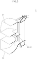
FIG. 5 is a cross-sectional view illustrating a duct type air guide in which a variable screen is installed according to an exemplary embodiment of the present invention; -
FIG. 6 is a perspective view illustrating an inside of a duct type air guide in which a variable screen is installed according to a first exemplary embodiment of the present invention; -
FIGS. 7A to 7D are views illustrating a duct coupling structure of the variable screen according to the first exemplary embodiment of the present invention; -
FIGS. 8A to 8C are views illustrating an operation scheme of the variable screen according to the first exemplary embodiment of the present invention; -
FIG. 9 is a perspective view illustrating an inside of a duct type air guide in which a variable screen is installed according to a second exemplary embodiment of the present invention; and -
FIGS. 10A to 10C are views illustrating an operation scheme of the variable screen according to the second exemplary embodiment of the present invention. - It is understood that the term "vehicle" or "vehicular" or other similar term as used herein is inclusive of motor vehicles in general such as passenger automobiles including sports utility vehicles (SUV), buses, trucks, various commercial vehicles, watercraft including a variety of boats and ships, aircraft, and the like, and includes hybrid vehicles, electric vehicles, combustion, plug-in hybrid electric vehicles, hydrogen-powered vehicles and other alternative fuel vehicles (e.g. fuels derived from resources other than petroleum).
- The terminology used herein is for the purpose of describing particular embodiments only and is not intended to be limiting of the invention. As used herein, the singular forms "a", "an" and "the" are intended to include the plural forms as well, unless the context clearly indicates otherwise. It will be further understood that the terms "comprises" and/or "comprising," when used in this specification, specify the presence of stated features, integers, steps, operations, elements, and/or components, but do not preclude the presence or addition of one or more other features, integers, steps, operations, elements, components, and/or groups thereof. As used herein, the term "and/or" includes any and all combinations of one or more of the associated listed items.
- Unless specifically stated or obvious from context, as used herein, the term "about" is understood as within a range of normal tolerance in the art, for example within 2 standard deviations of the mean. "About" can be understood as within 10%, 9%, 8%, 7%, 6%, 5%, 4%, 3%, 2%, 1%, 0.5%, 0.1%, 0.05%, or 0.01% of the stated value. Unless otherwise clear from the context, all numerical values provided herein are modified by the term "about."
- Hereinafter, an air guide structure of a vehicle according to the present invention will be described in detail with reference to the accompanying drawings. However, detailed descriptions for well-known functions or configurations will be omitted in order not to unnecessarily obscure the gist of the present invention.
-
FIG. 5 is a cross-sectional view illustrating a duct type air guide in which a variable screen is installed according to an exemplary embodiment of the present invention. Referring toFIG. 5 , in an air guide structure of a vehicle, a screen (e.g., partition wall) positioned between a radiator grille inlet duct (e.g., upper duct) 31 and a bumper grille inlet duct (e.g., lower duct) 32 is avariable screen 33' or 33" of which a shape or a position may be changed according to a pressure difference resulting from a difference in flow rate between an upper flow and a lower flow introduced through theducts variable screen 33' or 33" may be formed so that a shape or a position thereof may be changed, and each embodiment will be described below in detail. -
FIG. 6 is a perspective view illustrating an inside of a duct type air guide in which a variable screen is installed according to a first exemplary embodiment of the present invention. Referring toFIG. 6 , a position of the variable screen 33' according to a first exemplary embodiment of the present invention may be fixed between the radiatorgrille inlet duct 31 and the bumpergrille inlet duct 32 as in the related art, however, since a flexible material is used for the variable screen 33', a shape of the variable screen 33' may be changed according to a pressure difference between the upper flow and the lower flow introduced through theducts -
FIGS. 7A to 7D are views illustrating a duct coupling structure of the variable screen according to the first exemplary embodiment of the present invention. The variable screen 33' according to the first exemplary embodiment of the present invention may be fixed to aduct wall surface 34 between the radiatorgrille inlet duct 31 and the bumpergrille inlet duct 32, and may be fixed by various coupling methods such as bonding or fusion, rivet connection, forcible fitting, casing, and the like. - Referring to
FIG. 7A , when the variable screen 33' is fixedly coupled by bonding or fusion, a portion of a side surface of the variable screen 33' contacting theduct wall surface 34 is entirely or partially bonded or fused on theduct wall surface 34, and thus, the variable screen 33' is fixedly coupled to theduct wall surface 34 between the radiatorgrille inlet duct 31 and the bumpergrille inlet duct 32. Referring toFIG. 7B , when the variable screen 33' is fixedly coupled by rivet connection, aflange part 341 for connecting the variable screen 33' is formed on theduct wall surface 34. Theflange part 341 and one side portion of the variable screen 33' vertically overlap each other, and arivet 36 is driven, to fixedly couple the variable screen 33' to theduct wall surface 34 between the radiatorgrille inlet duct 31 and the bumpergrille inlet duct 32. - Referring to
FIG. 7C , when the variable screen 33' is fixedly coupled by forcible fitting, aflange part 341 for connecting the variable screen 33' is formed on theduct wall surface 34, a forciblefitting groove 342 is formed in theflange part 342, a forciblefitting protrusion 331 is formed at one side surface of the variable screen 33', and the forciblefitting protrusion 331 of the variable screen 33' is forcibly fitted into the forciblefitting groove 342 of theflange part 341. Accordingly, the variable screen 33' is fixedly coupled to theduct wall surface 34 between the radiatorgrille inlet duct 31 and the bumpergrille inlet duct 32. - Referring to
FIG. 7D , when the variable screen 33' is fixedly coupled by casing, ascreen holder 332 is attached on one side surface of the variable screen 33', a coupling aperture 343 in which thescreen holder 332 is fixedly coupled is formed in theduct wall surface 34. When the variable screen 33' is inserted into the duct while passing through the coupling aperture 343, thescreen holder 332 may be fitted in the coupling aperture 343, to fixedly couple the variable screen 33' to theduct wall surface 34 between the radiatorgrille inlet duct 31 and the bumpergrille inlet duct 32. -
FIGS. 8A to 8C are views illustrating an operation scheme of the variable screen according to the first exemplary embodiment of the present invention. Referring toFIGS. 8A to 8C , the shape of the variable screen 33' according to the first exemplary embodiment of the present invention may be changed according to the difference in flow rate between the twoducts - In other words, when the vehicle travels at high speed and the flow rate of the
lower duct 32 is increased, the variable screen may be deformed toward the upper duct 31 (seeFIG. 8A ). When the flow rate of theupper duct 31 is increased, the variable screen may be deformed toward the lower duct 32 (seeFIG. 8B ). Additionally, when the vehicle is stopped or travels at low speed, since a pressure difference does not occur, thevariable screen 33 may not be deformed (seeFIG. 8C ). Accordingly, flow rate distribution at a front surface of the intercooler may be performed more efficiently, and as a result, a flow rate of flow passing through the intercooler is increased, thereby improving cooling performance. -
FIG. 9 is a perspective view illustrating an inside of a duct type air guide in which a variable screen is installed according to a second exemplary embodiment of the present invention. Referring toFIG. 9 , avariable screen 33" according to a second exemplary embodiment of the present invention is formed so that a position thereof may be vertically changed between the radiatorgrille inlet duct 31 and the bumpergrille inlet duct 32. In particular, anupper frame 371 and alower frame 372 may be fixedly installed on theduct wall surface 34 between theducts vertical movement guide 373 that guides thevariable screen 33" to move vertically may be installed between theupper frame 371 and thelower frame 372. - Further, a
guide aperture 333 through which thevertical movement guide 373 passes may be formed in thevariable screen 33" to slidably couple thevariable screen 33" to thevertical movement guide 373. Meanwhile, apressure adjustment aperture 334 may be formed in thevariable screen 33" according to the second exemplary embodiment of the present disclosure to adjust an amount of vertical movement of thevariable screen 33" based on a pressure difference. Such apressure adjustment aperture 334 may also be applied to the variable screen 33' according to the first exemplary embodiment of the present invention. -
FIGS. 10A to 10C are views illustrating an operation scheme of the variable screen according to the second exemplary embodiment of the present invention. Referring toFIGS. 10A to 10C , a position of thevariable screen 33" according to the second exemplary embodiment of the present invention may be moved according to a difference in flow rate between the twoducts variable screen 33" toward a duct of which the flow rate is less than the other (e.g., a duct among a plurality of ducts having a lower flow rate than the remaining ducts), thereby decreasing a pressure difference resulting from the difference in flow rate. - In other words, when the vehicle travels at high speed and a flow rate of the
lower duct 32 is increased (e.g., greater than the flow rate of the upper duct 31), thevariable screen 33" moves toward the upper duct 31 (seeFIG. 10A ). When a flow rate of theupper duct 31 and a flow rate of thelower duct 32 are similar to each other, thevariable screen 33" may be positioned in the middle between theupper duct 31 and the lower duct 32 (seeFIG. 10B ). In addition, when the vehicle is stopped or travels at low speed, since a pressure difference does not occur, thevariable screen 33" moves toward thelower duct 32 due to the weight of the screen (seeFIG. 10C ). Accordingly, flow rate distribution at a front surface of the intercooler may be performed more efficiently, and as a result, a flow rate of flow passing through the intercooler is increased, thereby improving cooling performance. - The following Table 1 shows result data obtained by performing computational fluid dynamics analysis with respect to a volume of air passing through the intercooler at each vehicle speed, through comparison between a duct type air guide (Comparative Example 1) without a screen and a duct type air guide (Comparative Example 2) in which the fixed
screen 33 is installed to verify an effect of the duct type air guide in which thevariable screen 33' or 33" according to the present invention is installed.Table 1 Case Vehicle Speed (km/h) Volume of Air Passing Through Intercooler (m3/h) Present Invention 7 (Idle) 16.9 Comparative Example 1 13.4 Comparative Example 2 14.3 Present Invention 30 83.6 Comparative Example 1 82.0 Comparative Example 2 79.0 Present Invention 100 793.6 Comparative Example 1 771.2 Comparative Example 2 751.2 - As shown in Table 1 above, due to a volume of air passing through the intercooler, cooling performance of the intercooler is improved, and the duct type air guide having the
variable screen 33' or 33" according to the present invention has superior cooling performance over a full range of vehicle speed in comparison to Comparative Examples 1 and 2. Meanwhile, the duct type air guide (Comparative Example 2) in which the fixedscreen 33 is installed according to the related art has lower cooling performance even than the duct type air guide without a screen, except at the time of idling at which the vehicle speed does not exist. - In addition, for a vehicle in which the duct type air guide having the
variable screen 33' or 33" according to the present invention is installed, a volume of air passing through a radiator at the time of idling was increased as compared to that of a vehicle in which the duct type air guide (Comparative Example 2) having the fixedtype screen 33 is installed according to the related art, as shown in the following Table 2, from which it is confirmed that there is a collateral effect that the cooling performance of the radiator is improved as well.Table 2 Case Vehicle Speed (km/h) Volume of Air Passing Through Radiator (m3/h) Present Invention 7 (Idle) 3032.72 Comparative Example 2 2251.57 Present Invention 30 3122.15 Comparative Example 2 3121.03 Present Invention 100 4550.61 Comparative Example 2 4548.13 - In accordance with the exemplary embodiments of the present invention, the air guide structure of a vehicle may achieve the effect of improving cooling performance of the intercooler without increasing weight and costs. Additionally, as the cooling performance is improved, a temperature of supercharged air is decreased, such that power performance and fuel efficiency of the engine may be improved.
- The exemplary embodiments disclosed in the present specification and the accompanying drawings are used only for the purpose of describing the technical idea of the present invention and are not used to limit the scope of the present invention described in the appended claims. Therefore, it will be understood by those skilled in the art that various modifications may be made and that other equivalent embodiments are available.
Claims (17)
- An air guide structure of a vehicle in which a duct for introducing outdoor air into an air cooling device of an engine (20) includes an upper duct (31) positioned in a radiator grille (1) and a lower duct (32) positioned in a bumper grille (2), the air guide structure characterized by comprising
a variable screen (33',33") positioned between the upper duct (31) and the lower duct (32) and formed to have a shape or a position changed according to a difference in flow rate between upper flow and lower flow introduced through the upper duct (31) and the lower duct (32), respectively,
wherein the variable screen (33',33") is disposed on a duct wall surface (34) between the upper duct (31) and the lower duct (32). - The air guide structure of claim 1, wherein the variable screen (33',33") is formed of a material having elasticity to allow the shape of the variable screen to change.
- The air guide structure of claim 2, wherein the material having elasticity is a rubber material.
- The air guide structure of claim 2, wherein the shape of the variable screen (33',33") is changed according to the difference in flow rate between the upper duct (31) and the lower duct (32) occurring based on a vehicle speed of the vehicle to deform the variable screen (33',33") toward one of the upper duct (31) and the lower duct (32) having a lesser flow rate to decrease a pressure difference resulting from the difference in flow rate.
- The air guide structure of claim 4, wherein a pressure adjustment aperture (334) is formed in the variable screen (33',33") to adjust an amount of deformation of the variable screen according to the difference in flow rate.
- The air guide structure of claim 2, wherein the variable screen (33',33") is fixedly coupled to the duct wall surface (34) between the upper duct (31) and the lower duct (32) by bonding or fusion.
- The air guide structure of claim 2, wherein the variable screen (33',33") is fixedly coupled to the duct wall surface (34) between the upper duct (31) and the lower duct (32) by rivet connection.
- The air guide structure of claim 7, wherein a flange part (341) for connecting one side portion of the variable screen (33',33") using a rivet (36) is formed on the duct wall surface (34) between the upper duct (31) and the lower duct (32).
- The air guide structure of claim 2, wherein the variable screen (33',33") is fixedly coupled to the duct wall surface (34) between the upper duct (31) and the lower duct (32) by forcible fitting.
- The air guide structure of claim 9, wherein a flange part (341) for connecting the variable screen (33',33") is formed on the duct wall surface (34) between the upper duct (31) and the lower duct (32), a forcible fitting groove (342) is formed in the flange part (341), and a forcible fitting protrusion (331) is formed at one side surface of the variable screen (33',33"), the forcible fitting protrusion (331) being forcibly fitted into the forcible fitting groove (342) of the flange part (341).
- The air guide structure of claim 2, wherein the variable screen (33',33") is fixedly coupled to the duct wall surface (34) between the upper duct (31) and the lower duct (32) by casing.
- The air guide structure of claim 11, wherein a screen holder (332) is attached on one side surface of the variable screen (33',33"), a coupling aperture (343) in which the screen holder (332) is fixedly coupled is formed in the duct wall surface (34) between the upper duct (31) and the lower duct (32), and when the variable screen (33',33") is inserted into the duct while passing through the coupling aperture (343), the screen holder (332) is fitted in the coupling aperture (343), such that the variable screen (33',33") is fixedly coupled to the duct wall surface (34) between the upper duct (31) and the lower duct (32).
- The air guide structure of claim 1, wherein the position of the variable screen (33',33") is changed vertically between the upper duct (31) and the lower duct (32).
- The air guide structure of claim 13, wherein the position of the variable screen (33',33") is moved according to the difference in flow rate between the upper duct (31) and the lower duct (32) occurring based on a vehicle speed of the vehicle to move the variable screen (33',33") toward one of the upper duct (31) and the lower duct (32) having a lesser flow rate to decrease a pressure difference resulting from the difference in flow rate.
- The air guide structure of claim 14, wherein a pressure adjustment aperture (334) is formed in the variable screen (33',33") to adjust an amount of vertical movement of the variable screen (33',33") according to the difference in flow rate.
- The air guide structure of claim 13, wherein an upper frame (371) and a lower frame (372) are fixedly installed on the duct wall surface (34) between the upper duct (31) and the lower duct (32) while being vertically spaced apart from each other, and a vertical movement guide (373) that guides the variable screen (33',33") to move vertically is installed between the upper frame (371) and the lower frame (372).
- The air guide structure of claim 16, wherein a guide aperture(333) through which the vertical movement guide (373) passes is formed in the variable screen (33',33") to slidably couple the variable screen (33',33") to the vertical movement guide (373).
Applications Claiming Priority (1)
| Application Number | Priority Date | Filing Date | Title |
|---|---|---|---|
| KR1020170183528A KR102452713B1 (en) | 2017-12-29 | 2017-12-29 | Air Guide Structure of Vehicle |
Publications (2)
| Publication Number | Publication Date |
|---|---|
| EP3505736A1 true EP3505736A1 (en) | 2019-07-03 |
| EP3505736B1 EP3505736B1 (en) | 2020-08-26 |
Family
ID=64051319
Family Applications (1)
| Application Number | Title | Priority Date | Filing Date |
|---|---|---|---|
| EP18201765.7A Active EP3505736B1 (en) | 2017-12-29 | 2018-10-22 | Air guide structure of vehicle |
Country Status (4)
| Country | Link |
|---|---|
| US (1) | US10625595B2 (en) |
| EP (1) | EP3505736B1 (en) |
| KR (1) | KR102452713B1 (en) |
| CN (1) | CN109989823B (en) |
Families Citing this family (1)
| Publication number | Priority date | Publication date | Assignee | Title |
|---|---|---|---|---|
| US20250060177A1 (en) * | 2023-08-15 | 2025-02-20 | Valeo Systemes Thermiques | Stone guard |
Citations (4)
| Publication number | Priority date | Publication date | Assignee | Title |
|---|---|---|---|---|
| US20060095178A1 (en) * | 2004-10-29 | 2006-05-04 | Freightliner Llc | Controlling the flow of air through at least one vehicle opening at a front portion of the vehicle |
| US8316974B2 (en) * | 2008-12-22 | 2012-11-27 | Veritas Ag | Adjustable radiator grill arrangement |
| WO2013161497A1 (en) * | 2012-04-26 | 2013-10-31 | 日産自動車株式会社 | Vehicle cooling apparatus |
| KR20150124725A (en) * | 2014-04-29 | 2015-11-06 | 현대자동차주식회사 | Air guide unit for vehicle |
Family Cites Families (24)
| Publication number | Priority date | Publication date | Assignee | Title |
|---|---|---|---|---|
| KR100448196B1 (en) * | 2001-07-12 | 2004-09-13 | 기아자동차주식회사 | Air guard of intercooler for vehicle |
| DE10248440B4 (en) * | 2002-10-17 | 2008-09-18 | Daimler Ag | Air duct in the stem of a motor vehicle |
| KR100514534B1 (en) | 2002-11-15 | 2005-09-13 | 기아자동차주식회사 | Intercooler system in automobile |
| US7080704B1 (en) * | 2003-10-31 | 2006-07-25 | Polaris Industries Inc. | Heat exchanger system |
| JP4301124B2 (en) | 2004-09-02 | 2009-07-22 | トヨタ自動車株式会社 | Vehicle rectifier |
| SE530033C2 (en) * | 2006-06-30 | 2008-02-12 | Scania Cv Abp | Cooling device for a motor vehicle |
| DE102007033116A1 (en) | 2007-07-13 | 2009-01-15 | Behr Gmbh & Co. Kg | Front end module for vehicles |
| KR101362332B1 (en) | 2008-03-21 | 2014-02-12 | 한라비스테온공조 주식회사 | Front End Module |
| JP4661941B2 (en) * | 2008-11-06 | 2011-03-30 | トヨタ自動車株式会社 | Automobile and control method thereof |
| CA2759543C (en) | 2009-04-24 | 2013-07-09 | Honda Motor Co., Ltd. | Vehicle air guide duct structure |
| JP5620085B2 (en) * | 2009-10-26 | 2014-11-05 | 富士重工業株式会社 | Variable duct device |
| DE102010003635A1 (en) | 2010-04-01 | 2011-10-06 | Behr Gmbh & Co. Kg | Cooling air flow |
| DE102010055639A1 (en) | 2010-12-22 | 2012-06-28 | Volkswagen Ag | motor vehicle |
| JP5641340B2 (en) * | 2011-03-04 | 2014-12-17 | スズキ株式会社 | Intake device for fuel cell vehicle |
| KR101231539B1 (en) * | 2011-03-10 | 2013-02-07 | 기아자동차주식회사 | Wind Flux Concentration Guiding Device and Engine Room Layout Thereof |
| JP2012192810A (en) * | 2011-03-16 | 2012-10-11 | Aisin Seiki Co Ltd | Device for opening and closing grill shutter |
| US9061585B2 (en) * | 2011-03-31 | 2015-06-23 | Fuji Jukogyo Kabushiki Kaisha | Cooling air introduction apparatus for vehicle |
| US8434579B2 (en) * | 2011-06-24 | 2013-05-07 | Honda Motor Co., Ltd. | Air separator and air separator with ducting for maximum cooling and fuel economy |
| US20150041229A1 (en) * | 2013-08-08 | 2015-02-12 | Honda Motor Co., Ltd. | Front end arrangement with active radiator damper and active radiator control method |
| KR101518931B1 (en) | 2013-11-26 | 2015-05-11 | 현대자동차 주식회사 | Variable intake system for vehicle |
| CN103625269A (en) * | 2013-12-03 | 2014-03-12 | 重庆市嘉陵川江汽车制造有限公司 | Automotive flow guide device |
| FR3020602B1 (en) * | 2014-04-30 | 2017-12-22 | Valeo Systemes Thermiques | AIR GUIDE AND AIR GUIDE MODULE |
| US10293679B2 (en) * | 2014-11-18 | 2019-05-21 | Ford Global Technologies, Llc | Aerodynamic device to optimize air flow through heat exchangers |
| US9822696B2 (en) * | 2015-02-13 | 2017-11-21 | Ford Global Technologies, Llc | Turbocharger system having an air-cooled wastegate actuator |
-
2017
- 2017-12-29 KR KR1020170183528A patent/KR102452713B1/en active Active
-
2018
- 2018-10-03 US US16/151,236 patent/US10625595B2/en active Active
- 2018-10-18 CN CN201811213961.5A patent/CN109989823B/en active Active
- 2018-10-22 EP EP18201765.7A patent/EP3505736B1/en active Active
Patent Citations (4)
| Publication number | Priority date | Publication date | Assignee | Title |
|---|---|---|---|---|
| US20060095178A1 (en) * | 2004-10-29 | 2006-05-04 | Freightliner Llc | Controlling the flow of air through at least one vehicle opening at a front portion of the vehicle |
| US8316974B2 (en) * | 2008-12-22 | 2012-11-27 | Veritas Ag | Adjustable radiator grill arrangement |
| WO2013161497A1 (en) * | 2012-04-26 | 2013-10-31 | 日産自動車株式会社 | Vehicle cooling apparatus |
| KR20150124725A (en) * | 2014-04-29 | 2015-11-06 | 현대자동차주식회사 | Air guide unit for vehicle |
Also Published As
| Publication number | Publication date |
|---|---|
| US10625595B2 (en) | 2020-04-21 |
| KR102452713B1 (en) | 2022-10-11 |
| KR20190081173A (en) | 2019-07-09 |
| EP3505736B1 (en) | 2020-08-26 |
| US20190202284A1 (en) | 2019-07-04 |
| CN109989823A (en) | 2019-07-09 |
| CN109989823B (en) | 2022-03-15 |
Similar Documents
| Publication | Publication Date | Title |
|---|---|---|
| US11602985B2 (en) | Continuous cooling assembly | |
| US9212598B2 (en) | Modular cooling unit for automotive vehicle | |
| US20140159429A1 (en) | Front end module for vehicle | |
| JP2006232264A (en) | Air-conditioning unit | |
| EP3505736A1 (en) | Air guide structure of vehicle | |
| CN115447363A (en) | Automobile cooling module and new energy automobile | |
| US10048023B2 (en) | Heat exchanger shroud mount | |
| EP3663115B1 (en) | Cooling duct of high voltage battery system of vehicle | |
| KR102630134B1 (en) | Front end module for vehicle | |
| US20240194976A1 (en) | High voltage battery module | |
| CN219706679U (en) | Air inlet device and automobile | |
| CN208498212U (en) | Arrangement framework of front-end module of hybrid electric vehicle | |
| KR20130028424A (en) | Carrier for motor vehicle | |
| CN210970588U (en) | Rear-mounted air conditioner pipeline assembly and vehicle | |
| US20180105011A1 (en) | Hvac module for vehicle | |
| JP2004019487A (en) | Engine cooling structure | |
| KR20240000751A (en) | Compressing module for vehicle | |
| KR20220137254A (en) | Electronic expansion valve | |
| CN219600859U (en) | Outer machine of parking air conditioner and have its parking air conditioner | |
| US9694670B2 (en) | Under cover for heat suction | |
| CN216805349U (en) | Automobile front bumper and air guide piece thereof | |
| CN118651319B (en) | Automobile hood air inlet structure and automobile | |
| CN111907300A (en) | A vehicle air duct structure | |
| US20250163844A1 (en) | Cooling System for a Motor Vehicle | |
| EP4686586A1 (en) | Manifold |
Legal Events
| Date | Code | Title | Description |
|---|---|---|---|
| PUAI | Public reference made under article 153(3) epc to a published international application that has entered the european phase |
Free format text: ORIGINAL CODE: 0009012 |
|
| STAA | Information on the status of an ep patent application or granted ep patent |
Free format text: STATUS: THE APPLICATION HAS BEEN PUBLISHED |
|
| AK | Designated contracting states |
Kind code of ref document: A1 Designated state(s): AL AT BE BG CH CY CZ DE DK EE ES FI FR GB GR HR HU IE IS IT LI LT LU LV MC MK MT NL NO PL PT RO RS SE SI SK SM TR |
|
| AX | Request for extension of the european patent |
Extension state: BA ME |
|
| STAA | Information on the status of an ep patent application or granted ep patent |
Free format text: STATUS: REQUEST FOR EXAMINATION WAS MADE |
|
| 17P | Request for examination filed |
Effective date: 20191127 |
|
| RBV | Designated contracting states (corrected) |
Designated state(s): AL AT BE BG CH CY CZ DE DK EE ES FI FR GB GR HR HU IE IS IT LI LT LU LV MC MK MT NL NO PL PT RO RS SE SI SK SM TR |
|
| GRAP | Despatch of communication of intention to grant a patent |
Free format text: ORIGINAL CODE: EPIDOSNIGR1 |
|
| STAA | Information on the status of an ep patent application or granted ep patent |
Free format text: STATUS: GRANT OF PATENT IS INTENDED |
|
| INTG | Intention to grant announced |
Effective date: 20200320 |
|
| GRAS | Grant fee paid |
Free format text: ORIGINAL CODE: EPIDOSNIGR3 |
|
| GRAA | (expected) grant |
Free format text: ORIGINAL CODE: 0009210 |
|
| STAA | Information on the status of an ep patent application or granted ep patent |
Free format text: STATUS: THE PATENT HAS BEEN GRANTED |
|
| AK | Designated contracting states |
Kind code of ref document: B1 Designated state(s): AL AT BE BG CH CY CZ DE DK EE ES FI FR GB GR HR HU IE IS IT LI LT LU LV MC MK MT NL NO PL PT RO RS SE SI SK SM TR |
|
| REG | Reference to a national code |
Ref country code: GB Ref legal event code: FG4D |
|
| REG | Reference to a national code |
Ref country code: CH Ref legal event code: EP |
|
| REG | Reference to a national code |
Ref country code: AT Ref legal event code: REF Ref document number: 1306580 Country of ref document: AT Kind code of ref document: T Effective date: 20200915 |
|
| REG | Reference to a national code |
Ref country code: IE Ref legal event code: FG4D |
|
| REG | Reference to a national code |
Ref country code: DE Ref legal event code: R096 Ref document number: 602018007264 Country of ref document: DE |
|
| REG | Reference to a national code |
Ref country code: LT Ref legal event code: MG4D |
|
| PG25 | Lapsed in a contracting state [announced via postgrant information from national office to epo] |
Ref country code: SE Free format text: LAPSE BECAUSE OF FAILURE TO SUBMIT A TRANSLATION OF THE DESCRIPTION OR TO PAY THE FEE WITHIN THE PRESCRIBED TIME-LIMIT Effective date: 20200826 Ref country code: BG Free format text: LAPSE BECAUSE OF FAILURE TO SUBMIT A TRANSLATION OF THE DESCRIPTION OR TO PAY THE FEE WITHIN THE PRESCRIBED TIME-LIMIT Effective date: 20201126 Ref country code: GR Free format text: LAPSE BECAUSE OF FAILURE TO SUBMIT A TRANSLATION OF THE DESCRIPTION OR TO PAY THE FEE WITHIN THE PRESCRIBED TIME-LIMIT Effective date: 20201127 Ref country code: LT Free format text: LAPSE BECAUSE OF FAILURE TO SUBMIT A TRANSLATION OF THE DESCRIPTION OR TO PAY THE FEE WITHIN THE PRESCRIBED TIME-LIMIT Effective date: 20200826 Ref country code: NO Free format text: LAPSE BECAUSE OF FAILURE TO SUBMIT A TRANSLATION OF THE DESCRIPTION OR TO PAY THE FEE WITHIN THE PRESCRIBED TIME-LIMIT Effective date: 20201126 Ref country code: FI Free format text: LAPSE BECAUSE OF FAILURE TO SUBMIT A TRANSLATION OF THE DESCRIPTION OR TO PAY THE FEE WITHIN THE PRESCRIBED TIME-LIMIT Effective date: 20200826 Ref country code: PT Free format text: LAPSE BECAUSE OF FAILURE TO SUBMIT A TRANSLATION OF THE DESCRIPTION OR TO PAY THE FEE WITHIN THE PRESCRIBED TIME-LIMIT Effective date: 20201228 Ref country code: HR Free format text: LAPSE BECAUSE OF FAILURE TO SUBMIT A TRANSLATION OF THE DESCRIPTION OR TO PAY THE FEE WITHIN THE PRESCRIBED TIME-LIMIT Effective date: 20200826 |
|
| REG | Reference to a national code |
Ref country code: NL Ref legal event code: MP Effective date: 20200826 |
|
| REG | Reference to a national code |
Ref country code: AT Ref legal event code: MK05 Ref document number: 1306580 Country of ref document: AT Kind code of ref document: T Effective date: 20200826 |
|
| PG25 | Lapsed in a contracting state [announced via postgrant information from national office to epo] |
Ref country code: LV Free format text: LAPSE BECAUSE OF FAILURE TO SUBMIT A TRANSLATION OF THE DESCRIPTION OR TO PAY THE FEE WITHIN THE PRESCRIBED TIME-LIMIT Effective date: 20200826 Ref country code: RS Free format text: LAPSE BECAUSE OF FAILURE TO SUBMIT A TRANSLATION OF THE DESCRIPTION OR TO PAY THE FEE WITHIN THE PRESCRIBED TIME-LIMIT Effective date: 20200826 Ref country code: PL Free format text: LAPSE BECAUSE OF FAILURE TO SUBMIT A TRANSLATION OF THE DESCRIPTION OR TO PAY THE FEE WITHIN THE PRESCRIBED TIME-LIMIT Effective date: 20200826 Ref country code: NL Free format text: LAPSE BECAUSE OF FAILURE TO SUBMIT A TRANSLATION OF THE DESCRIPTION OR TO PAY THE FEE WITHIN THE PRESCRIBED TIME-LIMIT Effective date: 20200826 Ref country code: IS Free format text: LAPSE BECAUSE OF FAILURE TO SUBMIT A TRANSLATION OF THE DESCRIPTION OR TO PAY THE FEE WITHIN THE PRESCRIBED TIME-LIMIT Effective date: 20201226 |
|
| PG25 | Lapsed in a contracting state [announced via postgrant information from national office to epo] |
Ref country code: DK Free format text: LAPSE BECAUSE OF FAILURE TO SUBMIT A TRANSLATION OF THE DESCRIPTION OR TO PAY THE FEE WITHIN THE PRESCRIBED TIME-LIMIT Effective date: 20200826 Ref country code: CZ Free format text: LAPSE BECAUSE OF FAILURE TO SUBMIT A TRANSLATION OF THE DESCRIPTION OR TO PAY THE FEE WITHIN THE PRESCRIBED TIME-LIMIT Effective date: 20200826 Ref country code: RO Free format text: LAPSE BECAUSE OF FAILURE TO SUBMIT A TRANSLATION OF THE DESCRIPTION OR TO PAY THE FEE WITHIN THE PRESCRIBED TIME-LIMIT Effective date: 20200826 Ref country code: EE Free format text: LAPSE BECAUSE OF FAILURE TO SUBMIT A TRANSLATION OF THE DESCRIPTION OR TO PAY THE FEE WITHIN THE PRESCRIBED TIME-LIMIT Effective date: 20200826 Ref country code: SM Free format text: LAPSE BECAUSE OF FAILURE TO SUBMIT A TRANSLATION OF THE DESCRIPTION OR TO PAY THE FEE WITHIN THE PRESCRIBED TIME-LIMIT Effective date: 20200826 |
|
| REG | Reference to a national code |
Ref country code: DE Ref legal event code: R097 Ref document number: 602018007264 Country of ref document: DE |
|
| PG25 | Lapsed in a contracting state [announced via postgrant information from national office to epo] |
Ref country code: AL Free format text: LAPSE BECAUSE OF FAILURE TO SUBMIT A TRANSLATION OF THE DESCRIPTION OR TO PAY THE FEE WITHIN THE PRESCRIBED TIME-LIMIT Effective date: 20200826 Ref country code: AT Free format text: LAPSE BECAUSE OF FAILURE TO SUBMIT A TRANSLATION OF THE DESCRIPTION OR TO PAY THE FEE WITHIN THE PRESCRIBED TIME-LIMIT Effective date: 20200826 Ref country code: ES Free format text: LAPSE BECAUSE OF FAILURE TO SUBMIT A TRANSLATION OF THE DESCRIPTION OR TO PAY THE FEE WITHIN THE PRESCRIBED TIME-LIMIT Effective date: 20200826 |
|
| PG25 | Lapsed in a contracting state [announced via postgrant information from national office to epo] |
Ref country code: LU Free format text: LAPSE BECAUSE OF NON-PAYMENT OF DUE FEES Effective date: 20201022 Ref country code: MC Free format text: LAPSE BECAUSE OF FAILURE TO SUBMIT A TRANSLATION OF THE DESCRIPTION OR TO PAY THE FEE WITHIN THE PRESCRIBED TIME-LIMIT Effective date: 20200826 Ref country code: SK Free format text: LAPSE BECAUSE OF FAILURE TO SUBMIT A TRANSLATION OF THE DESCRIPTION OR TO PAY THE FEE WITHIN THE PRESCRIBED TIME-LIMIT Effective date: 20200826 |
|
| PLBE | No opposition filed within time limit |
Free format text: ORIGINAL CODE: 0009261 |
|
| STAA | Information on the status of an ep patent application or granted ep patent |
Free format text: STATUS: NO OPPOSITION FILED WITHIN TIME LIMIT |
|
| REG | Reference to a national code |
Ref country code: BE Ref legal event code: MM Effective date: 20201031 |
|
| PG25 | Lapsed in a contracting state [announced via postgrant information from national office to epo] |
Ref country code: IT Free format text: LAPSE BECAUSE OF FAILURE TO SUBMIT A TRANSLATION OF THE DESCRIPTION OR TO PAY THE FEE WITHIN THE PRESCRIBED TIME-LIMIT Effective date: 20200826 |
|
| 26N | No opposition filed |
Effective date: 20210527 |
|
| PG25 | Lapsed in a contracting state [announced via postgrant information from national office to epo] |
Ref country code: BE Free format text: LAPSE BECAUSE OF NON-PAYMENT OF DUE FEES Effective date: 20201031 Ref country code: SI Free format text: LAPSE BECAUSE OF FAILURE TO SUBMIT A TRANSLATION OF THE DESCRIPTION OR TO PAY THE FEE WITHIN THE PRESCRIBED TIME-LIMIT Effective date: 20200826 |
|
| PG25 | Lapsed in a contracting state [announced via postgrant information from national office to epo] |
Ref country code: IE Free format text: LAPSE BECAUSE OF NON-PAYMENT OF DUE FEES Effective date: 20201022 |
|
| REG | Reference to a national code |
Ref country code: CH Ref legal event code: PL |
|
| PG25 | Lapsed in a contracting state [announced via postgrant information from national office to epo] |
Ref country code: TR Free format text: LAPSE BECAUSE OF FAILURE TO SUBMIT A TRANSLATION OF THE DESCRIPTION OR TO PAY THE FEE WITHIN THE PRESCRIBED TIME-LIMIT Effective date: 20200826 Ref country code: MT Free format text: LAPSE BECAUSE OF FAILURE TO SUBMIT A TRANSLATION OF THE DESCRIPTION OR TO PAY THE FEE WITHIN THE PRESCRIBED TIME-LIMIT Effective date: 20200826 Ref country code: CY Free format text: LAPSE BECAUSE OF FAILURE TO SUBMIT A TRANSLATION OF THE DESCRIPTION OR TO PAY THE FEE WITHIN THE PRESCRIBED TIME-LIMIT Effective date: 20200826 |
|
| PG25 | Lapsed in a contracting state [announced via postgrant information from national office to epo] |
Ref country code: MK Free format text: LAPSE BECAUSE OF FAILURE TO SUBMIT A TRANSLATION OF THE DESCRIPTION OR TO PAY THE FEE WITHIN THE PRESCRIBED TIME-LIMIT Effective date: 20200826 |
|
| PG25 | Lapsed in a contracting state [announced via postgrant information from national office to epo] |
Ref country code: LI Free format text: LAPSE BECAUSE OF NON-PAYMENT OF DUE FEES Effective date: 20211031 Ref country code: CH Free format text: LAPSE BECAUSE OF NON-PAYMENT OF DUE FEES Effective date: 20211031 |
|
| P01 | Opt-out of the competence of the unified patent court (upc) registered |
Effective date: 20230512 |
|
| PGFP | Annual fee paid to national office [announced via postgrant information from national office to epo] |
Ref country code: GB Payment date: 20250922 Year of fee payment: 8 |
|
| PGFP | Annual fee paid to national office [announced via postgrant information from national office to epo] |
Ref country code: FR Payment date: 20250925 Year of fee payment: 8 |
|
| PGFP | Annual fee paid to national office [announced via postgrant information from national office to epo] |
Ref country code: DE Payment date: 20250922 Year of fee payment: 8 |