EP3505483A1 - An elevator car - Google Patents
An elevator car Download PDFInfo
- Publication number
- EP3505483A1 EP3505483A1 EP18150054.7A EP18150054A EP3505483A1 EP 3505483 A1 EP3505483 A1 EP 3505483A1 EP 18150054 A EP18150054 A EP 18150054A EP 3505483 A1 EP3505483 A1 EP 3505483A1
- Authority
- EP
- European Patent Office
- Prior art keywords
- car
- roof
- support mechanism
- actuator
- supported
- Prior art date
- Legal status (The legal status is an assumption and is not a legal conclusion. Google has not performed a legal analysis and makes no representation as to the accuracy of the status listed.)
- Withdrawn
Links
Images



Classifications
-
- B—PERFORMING OPERATIONS; TRANSPORTING
- B66—HOISTING; LIFTING; HAULING
- B66B—ELEVATORS; ESCALATORS OR MOVING WALKWAYS
- B66B11/00—Main component parts of lifts in, or associated with, buildings or other structures
- B66B11/02—Cages, i.e. cars
- B66B11/0226—Constructional features, e.g. walls assembly, decorative panels, comfort equipment, thermal or sound insulation
- B66B11/0246—Maintenance features
Definitions
- the invention relates to an elevator car.
- An elevator may typically comprise a car, an elevator shaft, lifting machinery, ropes, and a counter weight.
- the lifting machinery may comprise a drive sheave, a machinery brake, an electric motor, and a drive for the electric motor.
- the lifting machinery may move the car in a vertical direction upwards and downwards in the vertically extending shaft.
- the ropes may connect the car frame and thereby also the car via the drive sheave and other sheaves to the counter weight.
- the car frame may further be supported with gliding means on guide rails extending in the vertical direction in the shaft.
- the gliding means may comprise rolls rolling on the guide rails or gliding shoes gliding on the guide rails when the elevator car is mowing upwards and downwards in the shaft.
- the guide rails may be supported with fastening brackets on the side wall structures of the shaft.
- the gliding means engaging with the guide rails guide the car when the car moves upwards and downwards in the shaft.
- the counter weight may be supported in a corresponding way on guide rails supported on the wall structure of the shaft.
- the elevator car may transport people and/or goods between the landings in the building.
- the shaft may be formed of solid walls and/or of open steel structures.
- An object of the present invention is to present a novel elevator car.
- the elevator car is defined in claim 1.
- the elevator car comprises a bottom, a roof, and walls extending between the bottom and the roof.
- An actuator is provided for lifting and lowering the roof.
- a support mechanism is provided at each of two opposite edges of the roof of the car for supporting the roof of the car on the walls of the car during lifting and lowering of the roof of the car.
- Each support mechanism comprises two longitudinal intersecting arms being rotatably attached to each other in the intersection with a first articulated joint. Upper ends of the arms are supported on the roof of the car and lower ends of the arms are supported on the walls of the car.
- the support mechanism is only used for keeping the orientation of the roof during lifting and lowering of the roof makes it possible to use a simple, light and cheap support mechanism having a scissor like construction that may become totally flat in the rest position.
- the actuator may be a threaded bar operated by hand.
- the use of a threaded bar as actuator makes the arrangement simple and cheap.
- the threaded bar may be self-locking so that an external force is needed to rotate the threaded bar, i.e. the threaded bar cannot rotate by itself.
- the end of the threaded bar may be provided with an untypical turn head in order to make unauthorized use of the threaded bar more difficult.
- the support mechanism and the actuator are not in any way connected to each other i.e. the support mechanism and the actuator may be positioned freely in relation to each other.
- Figure 1 shows a vertical cross sectional view of an elevator.
- the elevator may comprise a car 10, a shaft 20, a counter weight or balance weight 30, a lifting machinery 40, a traction member 51, traction sheaves 61, 62, 63, 64, a suspension member 71 and diverting pulleys 81, 82, 83,84.
- the car 10 may comprise a bottom 11, a roof 12 opposite to the bottom 11, and walls 13 extending between the bottom 11 and the roof 12.
- the shaft 20 may comprise an upper end portion 22 and a lower end portion 23.
- the ceiling in the upper end portion 22 of the shaft 20 may be formed of the ceiling of the building.
- the lower end portion 23 of the shaft 20 ends into the bottom of the shaft 20.
- the lifting machinery 40 may comprise a motor 41 and a drive sheave 42.
- the lifting machinery 40 moves the car 10 upwards and downwards S1 in the shaft 20 between the landings L1-L4.
- the car 10 may thus transport people and/or goods between the landings L1-L4 in the shaft 20.
- At least one of the walls 13 of the car 10 may be provided with car doors providing access to the car 10 and from the car 10.
- Each of the landings L1-L4 is in a corresponding way provided with landing doors providing access from the car 10 to the landing L1-L4 and from the landing L1-L4 to the car 10.
- the car doors and the landing doors are not shown in the figures.
- a first traction sheave 61 may be attached to the lower end of the counterweight 30 and a first diverting pulley 81 may be attached to the upper end of the counterweight 30.
- the suspension of the car 10 and the moving of the car 10 may be realized with separate means.
- the suspension of the car 10 may be arranged with a suspension member 71 and the moving of the car 10 may be arranged with a traction member 51.
- the suspension member 71 may be connected between the car 10 and the counter weight 30.
- the suspension member 71 may be formed of a single member or of several parallel members.
- the suspension member 71 may be formed of a flat or round rope.
- a first end of the suspension member 71 may be fixed at a first fixing point 71 a positioned in the upper end portion 22 of the shaft 20 and a second end of the suspension member 71 may be fixed at a second fixing point 71 b also positioned in the upper end portion 22 of the shaft 20.
- the suspension member 71 runs from the first fixing point 71 a first downwards to the first diverting pulley 81 attached to the upper end of the counter weight 30, then upwards to a second diverting pulley 82 positioned at the upper end portion 22 of the shaft 20, then downwards to a third diverting pulley 83 attached to the bottom of the car 10 at one side of the car 10, then horizontally to a fourth diverting pulley 84 attached to the bottom of the car 10 at the opposite side of the car 10, and then finally upwards to the second fixing point 71 b.
- the suspension ratio of the suspension member 71 is 2:1 in this embodiment.
- the car 10 may on the other hand be driven by a traction member 51 connected between the car 10 and the counter weight 30.
- the traction member 51 may be formed of a single member or of several parallel members.
- the traction member 51 may be formed of a toothed belt, a chain or of some other type of traction member that does not slip on the drive sheave 42.
- a first end of the traction member 51 may be fixed at a first fixing point 51 a positioned in the lower end portion 23 of the shaft 20 and a second end of the traction member 51 may be fixed at a second fixing point 51 b also positioned in the lower end portion 23 of the shaft 20.
- the traction member 51 runs from the first fixing point 51 a first upwards to the first traction sheave 61 attached to the lower end of the counter weight 30, then downwards to a second traction sheave 62 positioned in the lower end portion 23 of the shaft 20, then horizontally to the drive sheave 42 in the lower end portion 23 of the shaft 20, then upwards to a third traction sheave 63 attached to a bottom of the car 10, then horizontally to a fourth traction sheave 64 attached to the bottom of the car 10, and then finally downwards to the second fixing point 51 b.
- the suspension ratio of the traction member 51 is 2:1 in this embodiment.
- the car 10 may be supported with gliding means 27 at guide rails 25 extending in the vertical direction in the shaft 20.
- the figure shows two guide rails 25 at opposite sides of the car 10.
- the gliding means 27 may comprise rolls rolling on the guide rails 25 or gliding shoes gliding on the guide rails 25 when the car 10 is moving upwards and downwards in the shaft 20.
- the counter weight 30 may be supported in a corresponding way on guide rails 25 that are attached to one or more walls of the shaft 20.
- the guide rails 25 may be attached with suitable fastening means (not shown in the figure) on the side walls 21 of the shaft 20.
- the cross section of the guide rails 25 may have the form of a letter T.
- the vertical branch of the guide rail element 25 may form three gliding surfaces for the gliding means 27 comprising rolls or gliding shoes. There may thus be two opposite side gliding surfaces and one front gliding surface in the guide rail 25.
- the cross-section of the gliding means 27 may have the form of a letter U so that the inner surface of the gliding means 27 sets against the three gliding surfaces of the guide rail 25.
- the gliding means 27 engage with the guide rails 25 and keep the elevator car 10 and/or the counter weight 30 in position in the horizontal plane when the car 10 and/or the counter weight 30 moves upwards and downwards in the shaft 20.
- the car 10 may advantageously be provided with an openable roof 12 in this kind of a suspension system as there is enough free space above the roof 12 to allow opening of the roof 12 outwards from the car 10.
- the car 10 may also be equipped with a safety gear system that is arranged to stop the movement of the car 10 and to lock the car 10 to the guide rails 25 in an emergency situation. This is not shown in the figures.
- the elevator may further comprise at least an operating system, a control system, an electrical system, a variety of sensor elements and a safety system comprising an inspection mode.
- the car 10 may be driven in the inspection mode with low speed when operations that require a safe working environment are performed e.g. inspection of the elevator, test of the elevator, maintenance or repair work of the elevator.
- Figure 2 shows a vertical cross sectional view of the upper portion of the elevator.
- the car 10 is in the figure at the uppermost landing L4 in the upper portion of the shaft 20.
- the top clearance between the roof 12 of the elevator car 10 and the ceiling 22 of the elevator shaft 20 has a minimum value in this position of the car 10.
- the height of the shaft 20 may be equal to the total height of the floors in the building or even slightly less than the total height of the floors of the building.
- Figure 3 shows a vertical cross sectional view of the upper portion of the elevator during a maintenance or reparation task.
- the roof 12 of the car 10 has been opened i.e. the roof 12 has been lifted upwards.
- the roof 12 of the car 10 may be lifted with an actuator and supported with a support mechanism 100 during the lifting.
- a maintenance opening is thus created between the upwards lifted roof 12 and the upper edges of the walls 13 of the car 10.
- the car 10 may be run in the inspection mode with a slow speed to appropriate locations in the shaft 20 so that maintenance personnel may reach elevator components in the shaft 20 from within the car 10 through the maintenance opening in the roof 12 of the car 10.
- the maintenance personnel may use a ladder e.g. an A-type ladder positioned on the floor of the car 10 in order to reach out from the maintenance opening in the roof 12 of the car 10.
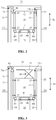
- Figure 4 shows an axonometric view of the elevator car with the support mechanism of the roof of the car.
- the walls 13 may comprise a front wall 13A, a back wall 13B opposite to the front wall 13A, and two opposite side walls 13C, 13D.
- the vertical edges of the side walls 13C, 13D may be connected to respective vertical edges of the front wall 13A and the back wall 13B.
- the car 10 may form a parallelepiped.
- One or more of the side walls 13A, 13B, 13C, 13D e.g. the front wall 13A may be provided with a door e.g. a centre opening slide door with two or more door panels.
- a support mechanism 100; 200 may be provided at each of two opposite edges of the roof 12 of the car 10 for supporting the roof 12 of the car 10 on the walls 13 of the car 10 during lifting and lowering of the roof 12 of the car 10.
- Each support mechanism 100; 200 may comprise two longitudinal intersecting arms 110, 120; 210, 220 being rotatably attached to each other in the intersection with a first articulated joint J10, J20.
- Upper ends 112, 121; 212, 221 of the arms 110, 120; 210, 220 may be supported on the roof 12.
- Lower ends 111, 122; 211, 222 of the arms 110, 120; 210, 220 may be supported on the walls 13 of the car 10.
- the intersecting arms 110, 120; 210, 220 being attached with the first articulated joints J10; J20 in each support mechanism 100; 200 form a scissor like construction.
- the first articulated joint J10; J20 may be positioned in a longitudinal middle point of the respective arms 110, 120; 210, 220.
- a lower end of the first arm 110; 210 of the support mechanism 100; 200 is rotatably attached with a second articulated joint J11; J21 to a wall 13 of the car 10, and a the upper end of the first arm 110; 210 of the support mechanism 100; 200 is movably R12; R22 supported on the roof 12 of the car 10.
- An upper end of the second arm 120; 220 of the support mechanism 100; 200 is rotatably attached with a third articulated joint J12; J22 to the roof 12 of the car 10 and a lower end of the second arm 120, 220 of the support mechanism 100; 200 is movably R11; R21 supported on a wall 13 of the car 10.
- the first articulated joints J11, J21 may be formed of stationary support points arranged in connection with an upper edge of the fourth wall 13D or in connection with the first wall 13A and the second wall 13B respectively.
- the first arms 110, 210 may turn around the first articulated joint J11; J21, but the first articulated joint J11; J21 is fixed in relation to the respective car wall 13.
- the second articulated joints J12; J22 may be formed of stationary support points in the roof 12.
- the second arms 120; 220 may turn around the second articulated joint J21; J22, but the articulated joint is fixed in relation to the roof 12.
- the lower movable supports R11; R21 may be realized with first rollers R11; R21.
- the first rollers R11; R21 may be positioned in respective car guide rails being supported on a respective wall 13.
- the upper movable supports R12; R22 may also be realized with second rollers R12; R22.
- the second rollers R12; R22 may be positioned in respective roof guide rails supported in the roof 12.
- the first articulated joints J10, J20 in the intersecting arms 110, 120; 210, 220 may be connected to each other with an intermediate arm 300.
- This intermediate arm 300 may run substantially horizontally between the first articulated joints J10, J20.
- the intermediate arm 300 is not necessary, but it may stabilize the construction further.
- the support mechanism 100; 200 at each of two opposite walls 13 of the car 10 will keep the roof 12 of the car 10 in a substantially horizontal direction when the roof 12 of the car 10 is raised upwards and lowered downwards.
- Figure 5 shows a vertical cross sectional view of the support mechanism of the roof of the elevator car.
- Each of the car guide rails 130 and 230 may be attached to a respective upper edge of a respective wall 13A, 13B of the car 10.
- Each of the roof guide rails 140 and 240 may be attached to the roof 12 of the car 10.
- the cross section of each of the car guide rails 130 and 230 and of each of the roof guide rails 140 and 240 may have a form of a horizontally turned letter U.
- the rollers R11, R12 and R21, R22 may thus be supported in a direction vertically upwards and in a direction vertically downwards within the guide rails 130, 140, 230, 240.
- the support arms 110, 120; 210, 220 may extend between the roof 12 of the car 10 and the upped edges of the walls 13A, 13B of the car 10 as shown in figure 4 .
- the centre points of the articulated joints J11, J12; J21, J22 may be on the same horizontal height as the centre points of the rollers R11, R12; R21, R22.
- the roof 12 is lifted i.e. there is an opening O1 from the upper edges of the walls 13 of the car 10.
- Figure 6 shows a side view of a first support mechanism of the roof of the elevator car.
- the first support mechanism 100 may comprise two longitudinal intersecting arms 110, 120 being attached to each other at the intersection with a first articulated joint J10.
- the first articulated joint J10 may be positioned substantially at a longitudinal middle point of each arm 110, 120.
- a lower end 111 of a first arm 110 of the first support mechanism 100 may be rotatably attached with a second articulated joint J11 to a wall 13 of the car 10.
- the second articulated joint J11 may be fixedly attached to the car wall 13.
- An upper end 112 of the first arm 110 may be movably R12 supported on a roof guide rail 140.
- the roof guide rail 140 may be attached to the roof 12 of the car 10.
- the movable support of the upper end 112 of the first arm 110 may be realized with a first roller R12.
- the first roller R12 may roll along the roof guide rail 140.
- the roof guide rail 140 may extend along the roof 12 e.g. in the horizontal direction X1.
- An upper end 121 of a second arm 120 of the first support mechanism 100 may be rotatably attached with a third articulated joint J12 to the roof 12 of the car 10.
- the third articulated joint J12 may be fixedly attached to the roof 12 of the car 10.
- the lower end 122 of the second arm 120 may be movably R11 supported on a car guide rail 130.
- the car guide rail 130 may be positioned at an upper edge of a wall in the car 10.
- the movable support of the upper end 122 of the second arm 120 may be realized with a second roller R11.
- the second roller R11 may roll along the car guide rail 130.
- the car guide rail 130 may extend along an upper edge of a wall 13 e.g. in the horizontal direction X1.
- Figure 7 shows a side view of a support mechanism of the roof of the elevator car.
- the second support mechanism 200 may be identical with the first support mechanism 100.
- the second support mechanism 200 may comprise two longitudinal intersecting arms 210, 220 being attached to each other at the intersection with a first articulated joint J20.
- the first articulated joint J20 may be positioned substantially at a longitudinal middle point of each arm 210, 220.
- a lower end 211 of a first arm 210 of the second support mechanism 200 may be rotatably attached with a second articulated joint J21 to a wall 13 of the car 10.
- the second articulated joint J21 may be fixedly attached to the car wall 13.
- An upper end 212 of the first arm 210 may be movably R22 supported on a roof guide rail 240.
- the roof guide rail 240 may be attached to the roof 12 of the car 10.
- the movable support of the upper end 212 of the first arm 210 may be realized with a first roller R22.
- the first roller R22 may roll along the roof guide rail 240.
- the roof guide rail 240 may extend along the roof 12 e.g. in the horizontal direction X1.
- An upper end 221 of a second arm 220 of the second support mechanism 200 may be rotatably attached with a third articulated joint J22 to the roof 12 of the car 10.
- the third articulated joint J22 may be fixedly attached to the roof 12 of the car 10.
- the lower end 222 of the second arm 220 may be movably R21 supported on a car guide rail 230.
- the car guide rail 230 may be positioned at an upper edge of a wall in the car 10.
- the movable support of the upper end 222 of the second arm 220 may be realized with a second roller R21.
- the second roller R21 may roll along the car guide rail 230.
- the car guide rail 230 may extend along an upper edge of a wall 13 e.g. in the horizontal direction X1.
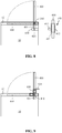
- Figure 8 shows a first embodiment of an actuator for lifting and lowering of the roof of the elevator.
- the actuator 400 for lifting and lowering of the roof 12 of the car 10 is shown in two different positions.
- the horizontal position drawn with broken lines is a rest position of the actuator 400 i.e. the actuator 400 is within the roof 12 of the car 10.
- the vertical position drawn with solid lines shows an operational position of the actuator 400.
- the actuator 400 may thus be raised from the rest position to the operational position and lowered from the operational position to the rest position by turning the actuator 400 around the third articulated joint J40.
- the actuator 400 may be formed of a threaded rod.
- the third articulated joint J40 may be constructed so that the rod 400 may be lifted from a horizontal position to a vertical position and vice a versa by turning around the third articulated joint J40.
- the arrangement in the third articulated joint J40 may comprise a bushing 410.
- the bushing 410 may comprise a swivel pin 411 extending outwards from the outer surface of the bushing 410 in a direction being perpendicular to the longitudinal direction of the bushing 410.
- the swivel pin 411 may be fitted in a swivel joint attached to an upper edge of a wall in the car 10.
- the bushing 410 may be provided with an internal threading mating with the external threading of the rod 400.
- the rod 400 is positioned within the bushing 410.
- a stopper 420 is attached to an upper edge of a wall in the car 10.
- the lower end 401 of the rod 400 will seat against the stopper 420 when the rod 400 is turned into the vertical direction.
- the stopper 420 may be provided with an opening 421 passing through the stopper 420.
- the lower end 401 of the rod 400 may be provided with a recess e.g. a rectangular recess into which a mating tool may be inserted through the opening 421.
- a handle may be connected to the tool or a cordless drill may be connected to the toll in order to rotate the rod 400 around its longitudinal centre axis. Rotation of the rod 400 will cause the roof 12 to rise as the lower end of the rod 400 is fixed against the stopper 420.
- Figure 9 shows a second embodiment of an actuator for lifting and lowering of the roof of the elevator.
- the actuator 400 for lifting and lowering of the roof 12 of the car 10 is shown in two different positions.
- the horizontal position drawn with broken lines is a rest position of the actuator 400 i.e. the actuator 400 is within the roof 12 of the car 10.
- the vertical position drawn with solid lines shows an operational position of the actuator 400.
- the actuator 400 may thus be raised from the rest position to the operational position and lowered from the operational position to the rest position by turning the actuator 400 around the third articulated joint J40.
- the actuator 400 may be formed of a threaded rod.
- the third articulated joint J40 may be constructed so that the rod 400 may be lifted from a horizontal position to a vertical position and vice a versa by turning around the third articulated joint J40.
- the arrangement in the third articulated joint J40 may comprise a swivel pin fitted in a swivel joint around which the actuator 400 may be turned.
- the arrangement must be such that the threaded rod 400 is rotatable around its longitudinal axis within the joint. The threaded rod 400 is thus locked against movement in the axial direction within the joint, but rotational movement of the threaded rod within the joint is allowed.
- a bushing 430 may be positioned on the threaded rod 400.
- the bushing 430 may have an internal threading mating with the external threading of the rod 400.
- a stopper 435 may be supported on the roof 12. The bushing 430 will thus seat against the stopper 435 when the threaded rod 400 is lifted into the vertical position.
- the lower end 401 of the rod 400 may be provided with e.g. a triangular or rectangular or polygonal cross section onto which a handle or a cordless drill may be connected in order to rotate the rod 400 around its longitudinal centre axis. Rotation of the rod 400 will cause the stopper 435 and thereby the roof 12 to rise as the threaded rod 400 is fixed against movement in the axial direction in the third articulated joint J40.
- the arrangement should be such that the actuator 400 is free to raise into the vertical position when the roof 12 is in the lowermost position.
- the arrangement in the figures is such that the actuator 400 is turned around the third articulated joint J40 so that the actuator 400 projects outwards from the upper end of the car 10.
- the arrangement could instead be reversed whereby the actuator 400 would be turned around the third articulated joint J40 so that the actuator 400 projects inwards into the car 10.
- the upper end of the actuator 400 could then seat against a stopper arranged in the roof 12 of the car 10.
- the actuator 400 could still be formed of a threaded bar 400. Turning of the threaded bar 400 from the lower end of the threaded bar 400 positioned in the car 10 would then move the threaded bar 400 axially upwards, whereby the roof 12 would be raised.
- the actuator 400 could also instead of being attached with a third articulated joint J40 to a wall 13 in the car 10 be formed of a separate part which is not attached to the car 10 at all.
- a space could be arranged in the roof 12 for storing the actuator 400.
- An openable hatch in the roof 12 could provide access to the actuator 400 from the inside of the car 10.
- the actuator 400 being a threaded rod 400 could then be connected to a threaded cylinder attached to a wall in the car 10.
- the upper end of the threaded rod 400 would then seat against a stopper attached to the roof 12. Turning of the threaded rod 400 around its axial centre axis would then move the threaded rod 400 upwards, whereby the roof 12 would be lifted upwards.
- the actuator 400 could also be stored in a space outside the elevator. The technician would then bring the actuator 400 with him into the car 10 in order to be able to open the roof 12 of the car 10 and to perform maintenance work in the shaft 20 through the opening O1 in the upper portion of the car 10.
- the support mechanism 100, 200 keeps the orientation of the roof 12 of the car 10 when the roof 12 is lifted upwards or lowered downwards with the actuator 400.
- the orientation of the roof 12 is essentially horizontal when the roof 12 is closed.
- the support mechanism 100, 200 keeps this essentially horizontal orientation of the roof 12 throughout the lifting and lowering of the roof 12 of the car 10.
- the lifting force is exclusively transferred from the roof 12 to the actuator 400 and from the actuator 400 to the walls 13 of the car 10.
- the support mechanism 100, 200 does not have to carry the weight of the roof 12 of the car 10 at all.
- the actuator 400 being a threaded rod 400 may be operated by hand e.g. by a crank handle to be attached to the lower end of the threaded bar 400.
- the lower end of the threaded rod 400 may have a cross sectional form that matches the cross sectional form of an opening in the crank handle.
- the actuator 400 being a threaded bar 400 may on the other hand be operated by a machine e.g. by a drilling machine.
- a cordless drilling machine powered by an accumulator may be used.
- the use of a threaded rod as actuator 400 makes the arrangement simple and cheap.
- the threaded rod 400 may be self-locking so that an external force is needed to rotate the threaded rod 400, i.e. the threaded rod 400 cannot rotate by itself.
- the end of the threaded rod 400 may be provided with an untypical turn head in order to make unauthorized use of the threaded rod 400 more difficult.
- Another possibility would be to use a hydraulic actuator 400 based e.g. on a piston-cylinder solution. Still another possibility would be to use an electrical actuator 400 based e.g. on a step motor.
- a disadvantage with these alternative arrangements is that they are expensive and require an external power source.
- the fact that the support mechanism 100; 200 only supports the roof 12 during lifting and lowering of the roof 12 makes it possible to use a simple, light and cheap support mechanism 100, 200 that may become totally flat in the rest position.
- the arms 110, 120; 210, 220 of the support mechanism 100; 200 may be parallel when the roof 12 is in the lowermost position. This would not be possible if the actuator 400 would be connected to the support mechanism 100; 200 i.e. the support mechanism 100; 200 would participate in the lifting of the roof 12.
- the support mechanism 100; 200 may be positioned fully within the roof 12 when the roof 12 is in the lowermost position.
- the support mechanism 100; 200 and the actuator 400 are thus totally separated in the arrangement. This makes it possible to use a one point actuator 400 for lifting and lowering the roof 12.
- the actuator 400 may be positioned freely within the car 10.
- the actuator 400 need not necessarily be positioned in the middle of the car 10.
- the actuator 400 may be positioned near a wall 13 in the car 10.
- the support mechanism 100; 200 will keep the orientation of the roof 12 during the lifting and lowering of the roof 12.
- the use of the invention is not limited to the type of elevator shown in the figures. E.g. the suspension arrangement and the traction arrangement shown in the figures is not a requirement for the use of the invention.
- the invention may be used in connection with any type of elevator. The only requirement is that there is enough free space above the roof 12 of the car 10 in order to allow the roof 12 to be lifted upwards from the car 10.
Landscapes
- Engineering & Computer Science (AREA)
- Civil Engineering (AREA)
- Mechanical Engineering (AREA)
- Structural Engineering (AREA)
- Cage And Drive Apparatuses For Elevators (AREA)
Abstract
Description
- The invention relates to an elevator car.
- An elevator may typically comprise a car, an elevator shaft, lifting machinery, ropes, and a counter weight. The lifting machinery may comprise a drive sheave, a machinery brake, an electric motor, and a drive for the electric motor. The lifting machinery may move the car in a vertical direction upwards and downwards in the vertically extending shaft. The ropes may connect the car frame and thereby also the car via the drive sheave and other sheaves to the counter weight. The car frame may further be supported with gliding means on guide rails extending in the vertical direction in the shaft. The gliding means may comprise rolls rolling on the guide rails or gliding shoes gliding on the guide rails when the elevator car is mowing upwards and downwards in the shaft. The guide rails may be supported with fastening brackets on the side wall structures of the shaft. The gliding means engaging with the guide rails guide the car when the car moves upwards and downwards in the shaft. The counter weight may be supported in a corresponding way on guide rails supported on the wall structure of the shaft. The elevator car may transport people and/or goods between the landings in the building. The shaft may be formed of solid walls and/or of open steel structures.
- An object of the present invention is to present a novel elevator car.
- The elevator car is defined in
claim 1. - The elevator car comprises a bottom, a roof, and walls extending between the bottom and the roof. An actuator is provided for lifting and lowering the roof. A support mechanism is provided at each of two opposite edges of the roof of the car for supporting the roof of the car on the walls of the car during lifting and lowering of the roof of the car. Each support mechanism comprises two longitudinal intersecting arms being rotatably attached to each other in the intersection with a first articulated joint. Upper ends of the arms are supported on the roof of the car and lower ends of the arms are supported on the walls of the car.
- The fact that the support mechanism is only used for keeping the orientation of the roof during lifting and lowering of the roof makes it possible to use a simple, light and cheap support mechanism having a scissor like construction that may become totally flat in the rest position.
- The actuator may be a threaded bar operated by hand. The use of a threaded bar as actuator makes the arrangement simple and cheap. The threaded bar may be self-locking so that an external force is needed to rotate the threaded bar, i.e. the threaded bar cannot rotate by itself. The end of the threaded bar may be provided with an untypical turn head in order to make unauthorized use of the threaded bar more difficult.
- The support mechanism and the actuator are not in any way connected to each other i.e. the support mechanism and the actuator may be positioned freely in relation to each other.
- The invention will in the following be described in greater detail by means of preferred embodiments with reference to the attached drawings, in which:
-
Figure 1 shows a vertical cross sectional view of an elevator, -
Figure 2 shows a vertical cross sectional view of the upper portion of the elevator, -
Figure 3 shows a vertical cross sectional view of the upper portion of the elevator during a maintenance or reparation task, -
Figure 4 shows an axonometric view of the elevator car with the support mechanism of the roof of the car, -
Figure 5 shows a vertical cross sectional view of the support mechanism of the roof of the car, -
Figure 6 shows a side view of a first support mechanism of the roof of the elevator car, -
Figure 7 shows a side view of a second support mechanism of the roof of the elevator car, -
Figure 8 shows a first embodiment of an actuator for lifting and lowering of the roof of the car, -
Figure 9 shows a second embodiment of an actuator for lifting and lowering of the roof of the elevator. -
Figure 1 shows a vertical cross sectional view of an elevator. - The elevator may comprise a
car 10, ashaft 20, a counter weight orbalance weight 30, alifting machinery 40, atraction member 51,traction sheaves suspension member 71 and divertingpulleys - The
car 10 may comprise abottom 11, aroof 12 opposite to thebottom 11, andwalls 13 extending between thebottom 11 and theroof 12. - The
shaft 20 may comprise anupper end portion 22 and alower end portion 23. The ceiling in theupper end portion 22 of theshaft 20 may be formed of the ceiling of the building. Thelower end portion 23 of theshaft 20 ends into the bottom of theshaft 20. - The
lifting machinery 40 may comprise amotor 41 and adrive sheave 42. Thelifting machinery 40 moves thecar 10 upwards and downwards S1 in theshaft 20 between the landings L1-L4. Thecar 10 may thus transport people and/or goods between the landings L1-L4 in theshaft 20. - At least one of the
walls 13 of thecar 10 may be provided with car doors providing access to thecar 10 and from thecar 10. Each of the landings L1-L4 is in a corresponding way provided with landing doors providing access from thecar 10 to the landing L1-L4 and from the landing L1-L4 to thecar 10. The car doors and the landing doors are not shown in the figures. - A
first traction sheave 61 may be attached to the lower end of thecounterweight 30 and a first divertingpulley 81 may be attached to the upper end of thecounterweight 30. - The suspension of the
car 10 and the moving of thecar 10 may be realized with separate means. The suspension of thecar 10 may be arranged with asuspension member 71 and the moving of thecar 10 may be arranged with atraction member 51. - The
suspension member 71 may be connected between thecar 10 and thecounter weight 30. Thesuspension member 71 may be formed of a single member or of several parallel members. Thesuspension member 71 may be formed of a flat or round rope. - A first end of the
suspension member 71 may be fixed at afirst fixing point 71 a positioned in theupper end portion 22 of theshaft 20 and a second end of thesuspension member 71 may be fixed at asecond fixing point 71 b also positioned in theupper end portion 22 of theshaft 20. - The
suspension member 71 runs from thefirst fixing point 71 a first downwards to the first divertingpulley 81 attached to the upper end of thecounter weight 30, then upwards to a second divertingpulley 82 positioned at theupper end portion 22 of theshaft 20, then downwards to a third divertingpulley 83 attached to the bottom of thecar 10 at one side of thecar 10, then horizontally to a fourth divertingpulley 84 attached to the bottom of thecar 10 at the opposite side of thecar 10, and then finally upwards to thesecond fixing point 71 b. The suspension ratio of thesuspension member 71 is 2:1 in this embodiment. - The
car 10 may on the other hand be driven by atraction member 51 connected between thecar 10 and thecounter weight 30. Thetraction member 51 may be formed of a single member or of several parallel members. Thetraction member 51 may be formed of a toothed belt, a chain or of some other type of traction member that does not slip on thedrive sheave 42. - A first end of the
traction member 51 may be fixed at afirst fixing point 51 a positioned in thelower end portion 23 of theshaft 20 and a second end of thetraction member 51 may be fixed at asecond fixing point 51 b also positioned in thelower end portion 23 of theshaft 20. - The
traction member 51 runs from thefirst fixing point 51 a first upwards to thefirst traction sheave 61 attached to the lower end of thecounter weight 30, then downwards to asecond traction sheave 62 positioned in thelower end portion 23 of theshaft 20, then horizontally to thedrive sheave 42 in thelower end portion 23 of theshaft 20, then upwards to athird traction sheave 63 attached to a bottom of thecar 10, then horizontally to afourth traction sheave 64 attached to the bottom of thecar 10, and then finally downwards to thesecond fixing point 51 b. The suspension ratio of thetraction member 51 is 2:1 in this embodiment. - Rotation of the
traction sheave 42 in either direction will move thecar 10 upwards and downwards S1 in theshaft 20. Thecounterweight 30 will move in an opposite direction in theshaft 20 in relation to thecar 10. - The
car 10 may be supported with gliding means 27 atguide rails 25 extending in the vertical direction in theshaft 20. The figure shows twoguide rails 25 at opposite sides of thecar 10. The gliding means 27 may comprise rolls rolling on the guide rails 25 or gliding shoes gliding on the guide rails 25 when thecar 10 is moving upwards and downwards in theshaft 20. - The
counter weight 30 may be supported in a corresponding way onguide rails 25 that are attached to one or more walls of theshaft 20. - The guide rails 25 may be attached with suitable fastening means (not shown in the figure) on the
side walls 21 of theshaft 20. The cross section of the guide rails 25 may have the form of a letter T. The vertical branch of theguide rail element 25 may form three gliding surfaces for the gliding means 27 comprising rolls or gliding shoes. There may thus be two opposite side gliding surfaces and one front gliding surface in theguide rail 25. The cross-section of the gliding means 27 may have the form of a letter U so that the inner surface of the gliding means 27 sets against the three gliding surfaces of theguide rail 25. - The gliding means 27 engage with the guide rails 25 and keep the
elevator car 10 and/or thecounter weight 30 in position in the horizontal plane when thecar 10 and/or thecounter weight 30 moves upwards and downwards in theshaft 20. - The
car 10 may advantageously be provided with anopenable roof 12 in this kind of a suspension system as there is enough free space above theroof 12 to allow opening of theroof 12 outwards from thecar 10. - The
car 10 may also be equipped with a safety gear system that is arranged to stop the movement of thecar 10 and to lock thecar 10 to the guide rails 25 in an emergency situation. This is not shown in the figures. - The elevator may further comprise at least an operating system, a control system, an electrical system, a variety of sensor elements and a safety system comprising an inspection mode. The
car 10 may be driven in the inspection mode with low speed when operations that require a safe working environment are performed e.g. inspection of the elevator, test of the elevator, maintenance or repair work of the elevator. -
Figure 2 shows a vertical cross sectional view of the upper portion of the elevator. - The
car 10 is in the figure at the uppermost landing L4 in the upper portion of theshaft 20. The top clearance between theroof 12 of theelevator car 10 and theceiling 22 of theelevator shaft 20 has a minimum value in this position of thecar 10. The height of theshaft 20 may be equal to the total height of the floors in the building or even slightly less than the total height of the floors of the building. -
Figure 3 shows a vertical cross sectional view of the upper portion of the elevator during a maintenance or reparation task. - The
roof 12 of thecar 10 has been opened i.e. theroof 12 has been lifted upwards. Theroof 12 of thecar 10 may be lifted with an actuator and supported with asupport mechanism 100 during the lifting. A maintenance opening is thus created between the upwards liftedroof 12 and the upper edges of thewalls 13 of thecar 10. Thecar 10 may be run in the inspection mode with a slow speed to appropriate locations in theshaft 20 so that maintenance personnel may reach elevator components in theshaft 20 from within thecar 10 through the maintenance opening in theroof 12 of thecar 10. The maintenance personnel may use a ladder e.g. an A-type ladder positioned on the floor of thecar 10 in order to reach out from the maintenance opening in theroof 12 of thecar 10. -
Figure 4 shows an axonometric view of the elevator car with the support mechanism of the roof of the car. - The
walls 13 may comprise afront wall 13A, aback wall 13B opposite to thefront wall 13A, and twoopposite side walls side walls front wall 13A and theback wall 13B. Thecar 10 may form a parallelepiped. One or more of theside walls front wall 13A may be provided with a door e.g. a centre opening slide door with two or more door panels. - A
support mechanism 100; 200 may be provided at each of two opposite edges of theroof 12 of thecar 10 for supporting theroof 12 of thecar 10 on thewalls 13 of thecar 10 during lifting and lowering of theroof 12 of thecar 10. - Each
support mechanism 100; 200 may comprise two longitudinal intersectingarms arms roof 12. Lower ends 111, 122; 211, 222 of thearms walls 13 of thecar 10. The intersectingarms support mechanism 100; 200 form a scissor like construction. The first articulated joint J10; J20 may be positioned in a longitudinal middle point of therespective arms - A lower end of the
first arm 110; 210 of thesupport mechanism 100; 200 is rotatably attached with a second articulated joint J11; J21 to awall 13 of thecar 10, and a the upper end of thefirst arm 110; 210 of thesupport mechanism 100; 200 is movably R12; R22 supported on theroof 12 of thecar 10. - An upper end of the
second arm 120; 220 of thesupport mechanism 100; 200 is rotatably attached with a third articulated joint J12; J22 to theroof 12 of thecar 10 and a lower end of thesecond arm support mechanism 100; 200 is movably R11; R21 supported on awall 13 of thecar 10. - The first articulated joints J11, J21 may be formed of stationary support points arranged in connection with an upper edge of the
fourth wall 13D or in connection with thefirst wall 13A and thesecond wall 13B respectively. Thefirst arms respective car wall 13. The second articulated joints J12; J22 may be formed of stationary support points in theroof 12. Thesecond arms 120; 220 may turn around the second articulated joint J21; J22, but the articulated joint is fixed in relation to theroof 12. - The lower movable supports R11; R21 may be realized with first rollers R11; R21. The first rollers R11; R21 may be positioned in respective car guide rails being supported on a
respective wall 13. The upper movable supports R12; R22 may also be realized with second rollers R12; R22. The second rollers R12; R22 may be positioned in respective roof guide rails supported in theroof 12. - The first articulated joints J10, J20 in the intersecting
arms intermediate arm 300. Thisintermediate arm 300 may run substantially horizontally between the first articulated joints J10, J20. Theintermediate arm 300 is not necessary, but it may stabilize the construction further. - The
support mechanism 100; 200 at each of twoopposite walls 13 of thecar 10 will keep theroof 12 of thecar 10 in a substantially horizontal direction when theroof 12 of thecar 10 is raised upwards and lowered downwards. -
Figure 5 shows a vertical cross sectional view of the support mechanism of the roof of the elevator car. - Each of the
car guide rails respective wall car 10. Each of theroof guide rails roof 12 of thecar 10. The cross section of each of thecar guide rails roof guide rails guide rails - The
support arms roof 12 of thecar 10 and the upped edges of thewalls car 10 as shown infigure 4 . The centre points of the articulated joints J11, J12; J21, J22 may be on the same horizontal height as the centre points of the rollers R11, R12; R21, R22. - The
roof 12 is lifted i.e. there is an opening O1 from the upper edges of thewalls 13 of thecar 10. -
Figure 6 shows a side view of a first support mechanism of the roof of the elevator car. - The
first support mechanism 100 may comprise two longitudinal intersectingarms arm - A
lower end 111 of afirst arm 110 of thefirst support mechanism 100 may be rotatably attached with a second articulated joint J11 to awall 13 of thecar 10. The second articulated joint J11 may be fixedly attached to thecar wall 13. Anupper end 112 of thefirst arm 110 may be movably R12 supported on aroof guide rail 140. Theroof guide rail 140 may be attached to theroof 12 of thecar 10. The movable support of theupper end 112 of thefirst arm 110 may be realized with a first roller R12. The first roller R12 may roll along theroof guide rail 140. Theroof guide rail 140 may extend along theroof 12 e.g. in the horizontal direction X1. - An
upper end 121 of asecond arm 120 of thefirst support mechanism 100 may be rotatably attached with a third articulated joint J12 to theroof 12 of thecar 10. The third articulated joint J12 may be fixedly attached to theroof 12 of thecar 10. Thelower end 122 of thesecond arm 120 may be movably R11 supported on acar guide rail 130. Thecar guide rail 130 may be positioned at an upper edge of a wall in thecar 10. The movable support of theupper end 122 of thesecond arm 120 may be realized with a second roller R11. The second roller R11 may roll along thecar guide rail 130. Thecar guide rail 130 may extend along an upper edge of awall 13 e.g. in the horizontal direction X1. -
Figure 7 shows a side view of a support mechanism of the roof of the elevator car. - The
second support mechanism 200 may be identical with thefirst support mechanism 100. - The
second support mechanism 200 may comprise two longitudinal intersectingarms arm - A
lower end 211 of afirst arm 210 of thesecond support mechanism 200 may be rotatably attached with a second articulated joint J21 to awall 13 of thecar 10. The second articulated joint J21 may be fixedly attached to thecar wall 13. Anupper end 212 of thefirst arm 210 may be movably R22 supported on aroof guide rail 240. Theroof guide rail 240 may be attached to theroof 12 of thecar 10. The movable support of theupper end 212 of thefirst arm 210 may be realized with a first roller R22. The first roller R22 may roll along theroof guide rail 240. Theroof guide rail 240 may extend along theroof 12 e.g. in the horizontal direction X1. - An
upper end 221 of asecond arm 220 of thesecond support mechanism 200 may be rotatably attached with a third articulated joint J22 to theroof 12 of thecar 10. The third articulated joint J22 may be fixedly attached to theroof 12 of thecar 10. Thelower end 222 of thesecond arm 220 may be movably R21 supported on acar guide rail 230. Thecar guide rail 230 may be positioned at an upper edge of a wall in thecar 10. The movable support of theupper end 222 of thesecond arm 220 may be realized with a second roller R21. The second roller R21 may roll along thecar guide rail 230. Thecar guide rail 230 may extend along an upper edge of awall 13 e.g. in the horizontal direction X1. -
Figure 8 shows a first embodiment of an actuator for lifting and lowering of the roof of the elevator. - The
actuator 400 for lifting and lowering of theroof 12 of thecar 10 is shown in two different positions. The horizontal position drawn with broken lines is a rest position of theactuator 400 i.e. theactuator 400 is within theroof 12 of thecar 10. The vertical position drawn with solid lines shows an operational position of theactuator 400. - The
actuator 400 may thus be raised from the rest position to the operational position and lowered from the operational position to the rest position by turning theactuator 400 around the third articulated joint J40. - The
actuator 400 may be formed of a threaded rod. The third articulated joint J40 may be constructed so that therod 400 may be lifted from a horizontal position to a vertical position and vice a versa by turning around the third articulated joint J40. - The arrangement in the third articulated joint J40 may comprise a
bushing 410. Thebushing 410 may comprise aswivel pin 411 extending outwards from the outer surface of thebushing 410 in a direction being perpendicular to the longitudinal direction of thebushing 410. Theswivel pin 411 may be fitted in a swivel joint attached to an upper edge of a wall in thecar 10. Thebushing 410 may be provided with an internal threading mating with the external threading of therod 400. Therod 400 is positioned within thebushing 410. - A
stopper 420 is attached to an upper edge of a wall in thecar 10. Thelower end 401 of therod 400 will seat against thestopper 420 when therod 400 is turned into the vertical direction. Thestopper 420 may be provided with anopening 421 passing through thestopper 420. Thelower end 401 of therod 400 may be provided with a recess e.g. a rectangular recess into which a mating tool may be inserted through theopening 421. A handle may be connected to the tool or a cordless drill may be connected to the toll in order to rotate therod 400 around its longitudinal centre axis. Rotation of therod 400 will cause theroof 12 to rise as the lower end of therod 400 is fixed against thestopper 420. -
Figure 9 shows a second embodiment of an actuator for lifting and lowering of the roof of the elevator. - The
actuator 400 for lifting and lowering of theroof 12 of thecar 10 is shown in two different positions. The horizontal position drawn with broken lines is a rest position of theactuator 400 i.e. theactuator 400 is within theroof 12 of thecar 10. The vertical position drawn with solid lines shows an operational position of theactuator 400. - The
actuator 400 may thus be raised from the rest position to the operational position and lowered from the operational position to the rest position by turning theactuator 400 around the third articulated joint J40. - The
actuator 400 may be formed of a threaded rod. The third articulated joint J40 may be constructed so that therod 400 may be lifted from a horizontal position to a vertical position and vice a versa by turning around the third articulated joint J40. - The arrangement in the third articulated joint J40 may comprise a swivel pin fitted in a swivel joint around which the
actuator 400 may be turned. The arrangement must be such that the threadedrod 400 is rotatable around its longitudinal axis within the joint. The threadedrod 400 is thus locked against movement in the axial direction within the joint, but rotational movement of the threaded rod within the joint is allowed. - A
bushing 430 may be positioned on the threadedrod 400. Thebushing 430 may have an internal threading mating with the external threading of therod 400. Astopper 435 may be supported on theroof 12. Thebushing 430 will thus seat against thestopper 435 when the threadedrod 400 is lifted into the vertical position. Thelower end 401 of therod 400 may be provided with e.g. a triangular or rectangular or polygonal cross section onto which a handle or a cordless drill may be connected in order to rotate therod 400 around its longitudinal centre axis. Rotation of therod 400 will cause thestopper 435 and thereby theroof 12 to rise as the threadedrod 400 is fixed against movement in the axial direction in the third articulated joint J40. - The arrangement should be such that the
actuator 400 is free to raise into the vertical position when theroof 12 is in the lowermost position. - The arrangement in the figures is such that the
actuator 400 is turned around the third articulated joint J40 so that the actuator 400 projects outwards from the upper end of thecar 10. The arrangement could instead be reversed whereby theactuator 400 would be turned around the third articulated joint J40 so that the actuator 400 projects inwards into thecar 10. The upper end of theactuator 400 could then seat against a stopper arranged in theroof 12 of thecar 10. Theactuator 400 could still be formed of a threadedbar 400. Turning of the threadedbar 400 from the lower end of the threadedbar 400 positioned in thecar 10 would then move the threadedbar 400 axially upwards, whereby theroof 12 would be raised. - The
actuator 400 could also instead of being attached with a third articulated joint J40 to awall 13 in thecar 10 be formed of a separate part which is not attached to thecar 10 at all. A space could be arranged in theroof 12 for storing theactuator 400. An openable hatch in theroof 12 could provide access to the actuator 400 from the inside of thecar 10. Theactuator 400 being a threadedrod 400 could then be connected to a threaded cylinder attached to a wall in thecar 10. The upper end of the threadedrod 400 would then seat against a stopper attached to theroof 12. Turning of the threadedrod 400 around its axial centre axis would then move the threadedrod 400 upwards, whereby theroof 12 would be lifted upwards. - The
actuator 400 could also be stored in a space outside the elevator. The technician would then bring theactuator 400 with him into thecar 10 in order to be able to open theroof 12 of thecar 10 and to perform maintenance work in theshaft 20 through the opening O1 in the upper portion of thecar 10. - The
support mechanism roof 12 of thecar 10 when theroof 12 is lifted upwards or lowered downwards with theactuator 400. The orientation of theroof 12 is essentially horizontal when theroof 12 is closed. Thesupport mechanism roof 12 throughout the lifting and lowering of theroof 12 of thecar 10. The lifting force is exclusively transferred from theroof 12 to theactuator 400 and from theactuator 400 to thewalls 13 of thecar 10. Thesupport mechanism roof 12 of thecar 10 at all. - The
actuator 400 being a threadedrod 400 may be operated by hand e.g. by a crank handle to be attached to the lower end of the threadedbar 400. The lower end of the threadedrod 400 may have a cross sectional form that matches the cross sectional form of an opening in the crank handle. - The
actuator 400 being a threadedbar 400 may on the other hand be operated by a machine e.g. by a drilling machine. A cordless drilling machine powered by an accumulator may be used. - The use of a threaded rod as
actuator 400 makes the arrangement simple and cheap. The threadedrod 400 may be self-locking so that an external force is needed to rotate the threadedrod 400, i.e. the threadedrod 400 cannot rotate by itself. The end of the threadedrod 400 may be provided with an untypical turn head in order to make unauthorized use of the threadedrod 400 more difficult. - Another possibility would be to use a
hydraulic actuator 400 based e.g. on a piston-cylinder solution. Still another possibility would be to use anelectrical actuator 400 based e.g. on a step motor. A disadvantage with these alternative arrangements is that they are expensive and require an external power source. - The fact that the
support mechanism 100; 200 only supports theroof 12 during lifting and lowering of theroof 12 makes it possible to use a simple, light andcheap support mechanism arms support mechanism 100; 200 may be parallel when theroof 12 is in the lowermost position. This would not be possible if theactuator 400 would be connected to thesupport mechanism 100; 200 i.e. thesupport mechanism 100; 200 would participate in the lifting of theroof 12. Thesupport mechanism 100; 200 may be positioned fully within theroof 12 when theroof 12 is in the lowermost position. - The
support mechanism 100; 200 and theactuator 400 are thus totally separated in the arrangement. This makes it possible to use a onepoint actuator 400 for lifting and lowering theroof 12. Theactuator 400 may be positioned freely within thecar 10. Theactuator 400 need not necessarily be positioned in the middle of thecar 10. Theactuator 400 may be positioned near awall 13 in thecar 10. Thesupport mechanism 100; 200 will keep the orientation of theroof 12 during the lifting and lowering of theroof 12. - The use of the invention is not limited to the type of elevator shown in the figures. E.g. the suspension arrangement and the traction arrangement shown in the figures is not a requirement for the use of the invention. The invention may be used in connection with any type of elevator. The only requirement is that there is enough free space above the
roof 12 of thecar 10 in order to allow theroof 12 to be lifted upwards from thecar 10. - It will be obvious to a person skilled in the art that, as the technology advances, the inventive concept can be implemented in various ways. The invention and its embodiments are not limited to the examples described above but may vary within the scope of the claims.
Claims (9)
- An elevator car (10) comprises a bottom (11), an openable roof (12), and walls (13) extending between the bottom (11) and the roof (12), characterised in that
an actuator (400) is provided for lifting and lowering the roof (12),
a support mechanism (100; 200) is provided at each of two opposite edges of the roof (12) of the car (10) for supporting the roof (12) of the car (10) on the walls (13) of the car (10) during lifting and lowering of the roof (12) of the car (10), each support mechanism (100, 200) comprising two longitudinal intersecting arms (110, 120; 210, 220) being rotatably attached to each other in the intersection with a first articulated joint (J10, J20), upper ends (112, 121; 212, 221) of the arms (110, 120; 210, 220) being supported on the roof (12) of the car (10) and lower ends (111, 122; 211, 222) of the arms (110, 120; 210, 220) being supported on the walls (13) of the car (10). - The elevator car (10) according to claim 1, wherein
the lower end (111; 211) of the first arm (110; 210) of the support mechanism (100; 200) is rotatably attached with a second articulated joint (J11; J21) to a wall (13) of the car (10), and a the upper end (112; 212) of the first arm (111; 211) of the support mechanism (100; 200) is movably (R1) supported on the roof (12) of the car (10),
the upper end (121; 221) of the second arm (120; 220) of the support mechanism (100; 200) is rotatably attached with a third articulated joint (J12; J22) to the roof (12) of the car (10) and the lower end (122, 222) of the second arm (120, 220) of the support mechanism (100; 200) is movably (R2) supported on a wall (13) of the car (10). - The elevator car (10) according to claim 2, wherein a roof guide rail (140; 240) is provided on a respective side in the roof (12) for movably supporting the second end (112; 212) of the first arm (110; 210) of the support mechanism (100, 200).
- The elevator car (10) according to claim 3, wherein the second end (112; 212) of the first arm (110; 210) in the support mechanism (100; 200) is supported with a second roller (R12; R22) on the roof guide rail (140; 240).
- The elevator car (10) according to any one of claims 2 to 4, wherein a car guide rail (130; 230) is provided on a respective wall (13) of the car (10) for movably supporting the second end (121, 221) of the second arm (120; 220) of the support mechanism (100, 200).
- The elevator car (10) according to claim 5, wherein the second end (122; 222) of the second arm (120; 220) in the support mechanism (100; 200) is supported with a first roller (R11; R21) on the car guide rail (130; 230).
- The elevator car (10) according to any one of claims 1 to 6, wherein the actuator (400) is a threaded bar.
- The elevator car (10) according to claim 7, wherein the actuator (400) is supported with a fourth articulated joint (J40) on the roof (12) of the car (12).
- The elevator car (10) according to claim 8, wherein the actuator (400) is bendable around the fourth articulated joint (J40) between an inactive position in which the actuator (400) is positioned within the roof (12) of the car (10) and an active position in which the actuator (400) is positioned in an upright position making it possible to lift the roof (12) with the actuator (400).
Priority Applications (1)
| Application Number | Priority Date | Filing Date | Title |
|---|---|---|---|
| EP18150054.7A EP3505483A1 (en) | 2018-01-02 | 2018-01-02 | An elevator car |
Applications Claiming Priority (1)
| Application Number | Priority Date | Filing Date | Title |
|---|---|---|---|
| EP18150054.7A EP3505483A1 (en) | 2018-01-02 | 2018-01-02 | An elevator car |
Publications (1)
| Publication Number | Publication Date |
|---|---|
| EP3505483A1 true EP3505483A1 (en) | 2019-07-03 |
Family
ID=60888337
Family Applications (1)
| Application Number | Title | Priority Date | Filing Date |
|---|---|---|---|
| EP18150054.7A Withdrawn EP3505483A1 (en) | 2018-01-02 | 2018-01-02 | An elevator car |
Country Status (1)
| Country | Link |
|---|---|
| EP (1) | EP3505483A1 (en) |
Citations (5)
| Publication number | Priority date | Publication date | Assignee | Title |
|---|---|---|---|---|
| JPS5961177U (en) * | 1982-10-15 | 1984-04-21 | 三菱電機株式会社 | elevator car room |
| DE10104351A1 (en) * | 2001-02-01 | 2002-08-22 | Ingenieurgesellschaft Foerder | Lift (elevator) with drive and control units traveling with cabin has these units mounted on cabin roof |
| EP1760029A1 (en) * | 2005-08-30 | 2007-03-07 | Inventio Ag | Elevator car comprising a maintenanec platform and method for servicing an elevator system |
| EP2277817A1 (en) * | 2009-07-21 | 2011-01-26 | Inventio AG | Lift with a cabin ceiling element that can be lowered |
| KR101768092B1 (en) * | 2016-05-30 | 2017-08-14 | (주)대한특수승강기 | Safety equipment for installing on elevator cage |
-
2018
- 2018-01-02 EP EP18150054.7A patent/EP3505483A1/en not_active Withdrawn
Patent Citations (5)
| Publication number | Priority date | Publication date | Assignee | Title |
|---|---|---|---|---|
| JPS5961177U (en) * | 1982-10-15 | 1984-04-21 | 三菱電機株式会社 | elevator car room |
| DE10104351A1 (en) * | 2001-02-01 | 2002-08-22 | Ingenieurgesellschaft Foerder | Lift (elevator) with drive and control units traveling with cabin has these units mounted on cabin roof |
| EP1760029A1 (en) * | 2005-08-30 | 2007-03-07 | Inventio Ag | Elevator car comprising a maintenanec platform and method for servicing an elevator system |
| EP2277817A1 (en) * | 2009-07-21 | 2011-01-26 | Inventio AG | Lift with a cabin ceiling element that can be lowered |
| KR101768092B1 (en) * | 2016-05-30 | 2017-08-14 | (주)대한특수승강기 | Safety equipment for installing on elevator cage |
Similar Documents
| Publication | Publication Date | Title |
|---|---|---|
| US12043519B2 (en) | Elevator system | |
| US11192754B2 (en) | Elevator arrangement and elevator | |
| KR101766914B1 (en) | Upper drive shaft operating system of retractable door-lift vertically for elevator | |
| US20190135586A1 (en) | Elevator arrangement with low headroom | |
| US20220194744A1 (en) | A self-climbing elevator arrangement for use during the construction of a building | |
| US11560291B2 (en) | Elevator arrangement to open the roof of an elevator car | |
| US11655121B2 (en) | Elevator car | |
| WO2015008386A1 (en) | Elevator car door lock device | |
| EP3484807B1 (en) | Elevator arrangement for safe maintenance work | |
| KR20010023844A (en) | Controller for elevator | |
| JP4404999B2 (en) | Elevator equipment | |
| DE02764699T1 (en) | MACHINE-ROOM-FREE DRIVE DISK ROLL | |
| JP2001048450A5 (en) | ||
| EP3604197B1 (en) | Elevator car | |
| JP5571130B2 (en) | Elevator equipment | |
| KR101039633B1 (en) | Horizontally driven door opener for up / down open / close elevator | |
| CN207226738U (en) | A kind of lifter for building construction | |
| KR101794202B1 (en) | Lower drive shaft operating system of retractable door-lift vertically for elevator | |
| JPH11217950A (en) | Turn table equipment of parking facility | |
| US20230202803A1 (en) | Elevator access doors | |
| CN223936051U (en) | Multiple traction type elevator | |
| KR20210055488A (en) | Hatch assembly | |
| EP4337584B1 (en) | An elevator system and method | |
| EP4691956A1 (en) | Elevator system and methods of installing and deinstalling a mobile working platform in such elevator system | |
| CN113896068A (en) | Integrated elevator self-rescue device and control method thereof |
Legal Events
| Date | Code | Title | Description |
|---|---|---|---|
| PUAI | Public reference made under article 153(3) epc to a published international application that has entered the european phase |
Free format text: ORIGINAL CODE: 0009012 |
|
| STAA | Information on the status of an ep patent application or granted ep patent |
Free format text: STATUS: THE APPLICATION HAS BEEN PUBLISHED |
|
| AK | Designated contracting states |
Kind code of ref document: A1 Designated state(s): AL AT BE BG CH CY CZ DE DK EE ES FI FR GB GR HR HU IE IS IT LI LT LU LV MC MK MT NL NO PL PT RO RS SE SI SK SM TR |
|
| AX | Request for extension of the european patent |
Extension state: BA ME |
|
| STAA | Information on the status of an ep patent application or granted ep patent |
Free format text: STATUS: REQUEST FOR EXAMINATION WAS MADE |
|
| 17P | Request for examination filed |
Effective date: 20191211 |
|
| RBV | Designated contracting states (corrected) |
Designated state(s): AL AT BE BG CH CY CZ DE DK EE ES FI FR GB GR HR HU IE IS IT LI LT LU LV MC MK MT NL NO PL PT RO RS SE SI SK SM TR |
|
| STAA | Information on the status of an ep patent application or granted ep patent |
Free format text: STATUS: EXAMINATION IS IN PROGRESS |
|
| 17Q | First examination report despatched |
Effective date: 20200528 |
|
| STAA | Information on the status of an ep patent application or granted ep patent |
Free format text: STATUS: THE APPLICATION IS DEEMED TO BE WITHDRAWN |
|
| 18D | Application deemed to be withdrawn |
Effective date: 20211005 |
|
| P01 | Opt-out of the competence of the unified patent court (upc) registered |
Effective date: 20230525 |