EP3505468A2 - Device for loading and unloading rail-bound suspended transport systems - Google Patents
Device for loading and unloading rail-bound suspended transport systems Download PDFInfo
- Publication number
- EP3505468A2 EP3505468A2 EP18209311.2A EP18209311A EP3505468A2 EP 3505468 A2 EP3505468 A2 EP 3505468A2 EP 18209311 A EP18209311 A EP 18209311A EP 3505468 A2 EP3505468 A2 EP 3505468A2
- Authority
- EP
- European Patent Office
- Prior art keywords
- conveyor
- unit
- rake
- units
- transfer
- Prior art date
- Legal status (The legal status is an assumption and is not a legal conclusion. Google has not performed a legal analysis and makes no representation as to the accuracy of the status listed.)
- Withdrawn
Links
Images


Classifications
-
- B—PERFORMING OPERATIONS; TRANSPORTING
- B65—CONVEYING; PACKING; STORING; HANDLING THIN OR FILAMENTARY MATERIAL
- B65G—TRANSPORT OR STORAGE DEVICES, e.g. CONVEYORS FOR LOADING OR TIPPING, SHOP CONVEYOR SYSTEMS OR PNEUMATIC TUBE CONVEYORS
- B65G47/00—Article or material-handling devices associated with conveyors; Methods employing such devices
- B65G47/52—Devices for transferring articles or materials between conveyors i.e. discharging or feeding devices
- B65G47/60—Devices for transferring articles or materials between conveyors i.e. discharging or feeding devices to or from conveyors of the suspended, e.g. trolley, type
- B65G47/61—Devices for transferring articles or materials between conveyors i.e. discharging or feeding devices to or from conveyors of the suspended, e.g. trolley, type for articles
-
- B—PERFORMING OPERATIONS; TRANSPORTING
- B65—CONVEYING; PACKING; STORING; HANDLING THIN OR FILAMENTARY MATERIAL
- B65G—TRANSPORT OR STORAGE DEVICES, e.g. CONVEYORS FOR LOADING OR TIPPING, SHOP CONVEYOR SYSTEMS OR PNEUMATIC TUBE CONVEYORS
- B65G17/00—Conveyors having an endless traction element, e.g. a chain, transmitting movement to a continuous or substantially-continuous load-carrying surface or to a series of individual load-carriers; Endless-chain conveyors in which the chains form the load-carrying surface
- B65G17/30—Details; Auxiliary devices
- B65G17/32—Individual load-carriers
- B65G17/34—Individual load-carriers having flat surfaces, e.g. platforms, grids, forks
-
- B—PERFORMING OPERATIONS; TRANSPORTING
- B65—CONVEYING; PACKING; STORING; HANDLING THIN OR FILAMENTARY MATERIAL
- B65G—TRANSPORT OR STORAGE DEVICES, e.g. CONVEYORS FOR LOADING OR TIPPING, SHOP CONVEYOR SYSTEMS OR PNEUMATIC TUBE CONVEYORS
- B65G17/00—Conveyors having an endless traction element, e.g. a chain, transmitting movement to a continuous or substantially-continuous load-carrying surface or to a series of individual load-carriers; Endless-chain conveyors in which the chains form the load-carrying surface
- B65G17/30—Details; Auxiliary devices
- B65G17/46—Means for holding or retaining the loads in fixed position on the load-carriers, e.g. magnetic
-
- B—PERFORMING OPERATIONS; TRANSPORTING
- B65—CONVEYING; PACKING; STORING; HANDLING THIN OR FILAMENTARY MATERIAL
- B65G—TRANSPORT OR STORAGE DEVICES, e.g. CONVEYORS FOR LOADING OR TIPPING, SHOP CONVEYOR SYSTEMS OR PNEUMATIC TUBE CONVEYORS
- B65G47/00—Article or material-handling devices associated with conveyors; Methods employing such devices
- B65G47/52—Devices for transferring articles or materials between conveyors i.e. discharging or feeding devices
- B65G47/56—Devices for transferring articles or materials between conveyors i.e. discharging or feeding devices to or from inclined or vertical conveyor sections
- B65G47/57—Devices for transferring articles or materials between conveyors i.e. discharging or feeding devices to or from inclined or vertical conveyor sections for articles
-
- B—PERFORMING OPERATIONS; TRANSPORTING
- B65—CONVEYING; PACKING; STORING; HANDLING THIN OR FILAMENTARY MATERIAL
- B65G—TRANSPORT OR STORAGE DEVICES, e.g. CONVEYORS FOR LOADING OR TIPPING, SHOP CONVEYOR SYSTEMS OR PNEUMATIC TUBE CONVEYORS
- B65G47/00—Article or material-handling devices associated with conveyors; Methods employing such devices
- B65G47/74—Feeding, transfer, or discharging devices of particular kinds or types
- B65G47/84—Star-shaped wheels or devices having endless travelling belts or chains, the wheels or devices being equipped with article-engaging elements
- B65G47/841—Devices having endless travelling belts or chains equipped with article-engaging elements
-
- B—PERFORMING OPERATIONS; TRANSPORTING
- B65—CONVEYING; PACKING; STORING; HANDLING THIN OR FILAMENTARY MATERIAL
- B65G—TRANSPORT OR STORAGE DEVICES, e.g. CONVEYORS FOR LOADING OR TIPPING, SHOP CONVEYOR SYSTEMS OR PNEUMATIC TUBE CONVEYORS
- B65G9/00—Apparatus for assisting manual handling having suspended load-carriers movable by hand or gravity
- B65G9/004—Loading or unloading arrangements
-
- B—PERFORMING OPERATIONS; TRANSPORTING
- B65—CONVEYING; PACKING; STORING; HANDLING THIN OR FILAMENTARY MATERIAL
- B65G—TRANSPORT OR STORAGE DEVICES, e.g. CONVEYORS FOR LOADING OR TIPPING, SHOP CONVEYOR SYSTEMS OR PNEUMATIC TUBE CONVEYORS
- B65G17/00—Conveyors having an endless traction element, e.g. a chain, transmitting movement to a continuous or substantially-continuous load-carrying surface or to a series of individual load-carriers; Endless-chain conveyors in which the chains form the load-carrying surface
- B65G17/20—Conveyors having an endless traction element, e.g. a chain, transmitting movement to a continuous or substantially-continuous load-carrying surface or to a series of individual load-carriers; Endless-chain conveyors in which the chains form the load-carrying surface comprising load-carriers suspended from overhead traction chains
-
- B—PERFORMING OPERATIONS; TRANSPORTING
- B65—CONVEYING; PACKING; STORING; HANDLING THIN OR FILAMENTARY MATERIAL
- B65G—TRANSPORT OR STORAGE DEVICES, e.g. CONVEYORS FOR LOADING OR TIPPING, SHOP CONVEYOR SYSTEMS OR PNEUMATIC TUBE CONVEYORS
- B65G2201/00—Indexing codes relating to handling devices, e.g. conveyors, characterised by the type of product or load being conveyed or handled
- B65G2201/02—Articles
- B65G2201/0288—Signatures, i.e. sections of printed magazines, papers or books
Definitions
- the present invention relates to the field of transport and conveyor technology. It relates to a system for transferring unit load units to and / or conveyor units of a rail-mounted overhead conveyor system. It further relates to a conveyor unit for a suspended conveyor system, and to a method for transferring unit-load units to and / or conveyor units of a suspended conveyor system.
- piece goods are generally understood as individually transportable units, such as workpieces, semifinished products and products in production processes, spare parts, consumer goods, stacks of stackable goods, for example stacks of printed products, but also containers and transport carriers for goods, such as boxes, containers, Luggage, barrels, packages, pallets, etc.
- Rail-mounted overhead conveyor systems may be implemented as chain conveyor systems in which a plurality of conveyor units forming links of a chain are moved along a conveyor path.
- Rail-guided overhead conveyor systems with individually transportable transport units are also known.
- WO 2016/030275 A1 also published as US 2018/215547 A1
- a gravity-driven conveyor system in which individual equipped with wheels conveyor units move on corresponding rails.
- Turnout systems allow a targeted distribution of individual conveyor units, which may be configured for example as a carriage, on different conveyor paths, or the merging of conveyor units on a common conveyor path. Jams allow buffering or storage of multiple carriages at a minimum distance. Separation systems in turn allow the targeted release of dammed conveyor units.
- the conveyor units On descending conveyor lines, the conveyor units can be energy-efficiently conveyed by gravity.
- the conveyor units can be reversibly coupled to drive devices such as chain drives or worm drives, so as to overcome height differences or achieve timed delivery in a particular area of the conveyor path.
- Overhead conveyor systems allow a large part of the conveyor system to be mounted overhead on the ceiling so that the floor space remains free for production facilities and other equipment.
- the conveying path must be brought to a lower level or brought back upwards, which requires a lot of floor space and volume due to the limited slope angle of rail-mounted overhead conveyor systems, which could be used elsewhere.
- Overhead conveyor systems with transport units are particularly suitable for the efficient transport of heterogeneous general cargo.
- overhead conveyor systems can be used to store a variety of articles of various sizes and weights, and to pick and deliver groups of articles according to the individual customer orders.
- Another area of application is the promotion and storage of intermediates and / or end products in print production processes.
- An aspect that is relevant for a suspended conveyor system is the simple, smooth and efficient introduction of piece goods into empty transport units and removal of the piece goods from the transport units, but also an efficient transfer between different conveyor systems, and a low requirement for volume and floor area.
- WO 2014/191162 A1 shows a system for sorting luggage in a belt conveyor based baggage transport system of an airport.
- the sorting system comprises a continuously revolving paternoster device with a large number of revolving transport units, each consisting of a horizontal belt conveyor table.
- a piece of luggage to be sorted is fed on a belt conveyor of the sorting device, and passed over a pivotable transfer belt conveyor to a passing transport unit.
- the belt conveyor of the corresponding transport unit runs synchronously to the transfer belt conveyor.
- the belt conveyor of the transport unit is stopped and the piece of luggage moves with the transport unit.
- the piece of luggage can then be delivered in an analogous manner to one of several takeover belt conveyors, whereby a sorting is achieved.
- the system corresponds to a multiple switch for belt conveyors with several possible inputs and outputs.
- WO 2012/155169 A1 and WO 2013/006879 A2 show shelf storage systems in which storage containers can be introduced with a continuously rotating paternoster device with a large number of circulating transport units in the desired level of the shelf storage and removed from this.
- the transport units each consist of a constantly level rake with three to four tines, on which the storage container rests during the promotion.
- the tines of the rake are aligned parallel or perpendicular to the circumferential plane of the paternoster device and form a constant horizontal plane.
- a conveyor unit comprising a plurality of parallel belt conveyors or a roller conveyor with parallel rollers which mesh with the tines of the transport unit interact. If a loaded transport unit moves past the delivery unit from above, the storage container remains lying on the delivery unit. This then conveys the storage container to an external belt conveyor through the belt conveyors or roller conveyors.
- An exchange of storage containers between external belt conveyors and paternoster device is possible only in the vertical sections of the conveying path of the paternoster device. So that several external belt conveyors can be operated, the unused conveyor units must be swung out of the conveying path.
- DE 102013104423 A1 shows a similar device for transferring a piece goods from a first belt conveyor or a vehicle to an overlying second belt conveyor, in which three transport blades are arranged with a computing ground on a vertical carousel constantly aligned horizontally.
- a conveying unit interacting in a meshing manner with the horizontal computing base of the transport blades takes over the piece goods from a transport bucket which passes by them from above by means of parallel narrow belt conveyors and conveys them to the external belt conveyor. Due to its design, said device requires a considerable volume of space compared to the height difference that has been overcome.
- the above-mentioned devices require a large number of complex driven or moving feed and discharge devices. A transfer of the piece goods is only possible on belt conveyor systems or conveyor vehicles.
- the object of the invention is to provide a system for transferring unit load units to and / or conveyor units of a rail-mounted overhead conveyor system which does not have the above-mentioned and other disadvantages.
- a system for transferring unit load units to and / or conveyor units of a rail-mounted overhead conveyor system which does not have the above-mentioned and other disadvantages.
- such a system should enable an efficient transfer of piece goods to rail-mounted overhead conveyor systems, or an efficient takeover of piece goods from rail-mounted overhead conveyor systems.
- Another object of the invention is to provide an advantageous conveyor unit for a suspended conveyor system, which can be used in particular in a system according to the invention;
- Yet another object of the invention is to provide an advantageous method for transferring unit load units to and / or conveyor units of a suspension conveyor system, which enable an efficient transfer of piece goods to overhead conveyor systems, or an efficient takeover of piece goods from overhead conveyor systems allows.
- a first aspect of the disclosure relates to a system for transferring unit load units to and / or conveyor units of a rail-guided overhead conveyor system, in particular a single-carriage-based overhead conveyor system or a conveyor chain system.
- a system for transferring unit load units to and / or conveyor units of a rail-mounted overhead conveyor system comprises at least one transfer conveyor with one or more first conveyor units, wherein the individual first conveyor units have a rake, with a plurality of tines, which has a receptacle for storing a Form general cargo unit; and an overhead conveyor system having a plurality of second conveyor units, the individual second conveyor units having a rake with a plurality of tines forming a receptacle for storing a general cargo unit.
- the at least one transfer conveyor and the overhead conveyor system are configured such that in a transfer zone, a rake of a first conveyor unit of the transfer conveyor and a rake of a second conveyor unit of the overhead conveyor system intermesh, so that upon movement of the first and the second conveyor unit relative to each other either a first stored on the rake of the first conveyor unit unit remains on the rake of the second conveyor unit, or a first stored on the rake of the second conveyor unit cargo unit remains lying on the rake of the first conveyor unit.
- the recording of the first conveyor units and / or the inclusion of the second conveyor units can be configured as at least one wall or as a trough.
- the rakes of the first conveyor units may, for example, have five individual prongs.
- the number of tines can also be smaller, minimum two, or larger, with the number of the concrete dimensioning of the system, for example, the width of the conveyor units, from the cooperating conveyor units of a suspension conveyor system, but also from the nature of the transportable Indeedgut- Units results.
- the second conveyor units of the overhead conveyor system can advantageously be conveyed individually, independently of other second conveyor units.
- the first conveyor units move along a closed conveyor path, wherein a section of this conveyor path corresponds to the transfer zone.
- the first conveyor units can move on a conveying path between the transfer zone and at least one further zone.
- the conveying path of the first conveying units and the conveying path of the second conveying units extend in a plane in the transfer zone.
- the conveying path of the first conveying units and the conveying path of the second conveying units extend in a common plane.
- the at least one transfer conveyor device has means for changing the orientation of the rake of a first conveyor unit with respect to the vertical.
- the at least one transfer conveyor device has means for controlling the orientation of the rake of a first conveyor unit.
- the orientation of the rake in dependence on the position of the first conveyor unit on the conveying path is controlled particularly advantageously.
- the prongs of the rake of a first conveyor unit are arranged secured against rotation on an axis of rotation of the first conveyor unit; and the transfer conveyor has two parallel Guided closed drive chains on which are arranged in pairs opposite pivot bearing, in each of which the axis of rotation of a conveyor unit is rotatably mounted.
- the first conveyor units of the at least one transfer conveyor device particularly advantageously have at one or both ends of the axis of rotation a control lever operatively connected to the axis of rotation, which interacts with control means of the transfer conveyor.
- a slotted guide or an actuator may be used to control the orientation of the rake of the first conveyor units.
- the rake of the first conveyor units is advantageously oriented so that the walls of the rake are aligned parallel to the walls of the second conveyor units of the overhead conveyor system.
- the rakes can be aligned by, for example, a corresponding positioning of a guide slot so that a wall is aligned horizontally so as to take a piece-unit from a horizontal belt conveyor or handed over to a horizontal belt conveyor.
- an active control of the orientation of the rake by, for example, actuators are provided which change a guide slot if necessary, for example by moving the guide slot.
- the suspended conveyor system of a system according to the invention can have means for changing the orientation of the rake of a second conveyor unit with respect to the vertical.
- the suspended conveyor system of a system according to the invention may further comprise means for controlling the orientation of the rake of a second conveyor unit.
- the control of the orientation of the rake in dependence on the position of the second conveyor unit takes place on the conveying path.
- the second conveyor units of the overhead conveyor system have means for clamping holding a unit-load unit mounted therein.
- the overhead conveyor system has means for locking and unlocking the means for clamping holding.
- the overhead conveyor system of a system according to the invention may comprise means which in a transfer zone of the conveying path of the second conveyor units, the orientation fix the second conveyor units with respect to the conveyor path. This allows during the transfer of cargo unit an exact alignment of the two conveyor units to each other.
- the tines of the rakes of the first conveyor units and / or the tines of the rakes of the second conveyor units each form a first wall and a second wall which are at an angle ⁇ 180 ° to one another.
- the angle is advantageously 90 ° or more to avoid jamming stored in the rake general cargo units.
- the tines can be designed so that in combination forms a non-planar bearing surface, such as a trough in the form of the cargo type to be transported, or a rounded transition between the two walls.
- the tines of the first conveyor units and / or the second conveyor units can be designed, for example, as metal elements, for example metal sheets, with which the bearing surface of the rake results from the entirety of the edges. It can also be provided additional sheet-like elements, such as metal strips or Kantenwülste, which increase the support surface.
- the tines can be flat on the side of the bearing surfaces, or have a structure which, for example, increases the adhesion. Likewise, the static friction can be lowered, for example by sliding surfaces made of HDPE or PTFE. Also possible is the arrangement of rollers with a on the bearing surfaces of the tines.
- the tines can also be configured as longitudinal rollers rotating along a tine axis. The aforementioned rollers may be free-rotating and / or driven. Alternatively, the tines may each include a narrow belt conveyor.
- the at least one transfer conveyor device is configured such that in at least one region of the conveying paths of the first conveyor units and the second conveyor units the first wall of the rake of a first conveyor unit is parallel to the first wall of the rake of a second conveyor unit.
- said at least one region of the conveying paths of the first conveying units and of the second conveying units lies in a transfer zone of the installation according to the invention.
- the at least one transfer conveyor device is advantageously designed such that the first wall of the rake of a first conveyor unit is horizontal at at least one point of the conveying path of the first conveyor units.
- a further conveying device which is formed at an end facing the transfer conveyor of several parallel belt conveyors or a roller conveyor with spaced parallel rollers, which are located in the conveying path of the first conveyor unit, and with the rake of the first Interacting conveyor units interact so that when a first conveyor unit passes through the further conveyor, the rake of the first conveyor unit penetrates the parallel running belt conveyor or the spaced parallel rollers of the roller conveyor of said further conveyor device.
- a second aspect of the disclosure relates to a transfer conveyor for vertically transporting unit load units between a first zone and an underlying at least one second zone.
- a transfer conveyor can advantageously be used in particular in a system according to the invention, as has been discussed above.
- Such an advantageous transfer conveyor device for the vertical transport of piece goods units between a first zone and an underlying at least one second zone has one or more conveyor units, wherein the individual conveyor units have a rake, with a plurality of tines, which for storage of a unit load unit at least first Form wall and a second wall, which are at an angle ⁇ 180 ° to each other, in particular a right angle or an obtuse angle.
- the conveyor units move along a closed conveyor path, with certain sections of the conveyor path corresponding to the different zones.
- the conveyor units can move on a conveying path between the first zone and at least one further second zone.
- a transfer conveyor means may be provided to control the orientation of the rake a conveyor unit, particularly advantageous depending on the location on the conveyor path.
- the prongs of the rake of a conveyor unit of a transfer conveyor are advantageously arranged against rotation on a rotation axis of the conveyor unit; and the device has two parallel closed drive chains, on which pairs opposite pivot bearings are arranged, in each of which the axis of rotation of a conveyor unit is rotatably mounted.
- the conveyor units at one or both ends of the axis of rotation particularly advantageously have a control lever operatively connected to the rotation axis, which interacts with control means of the transfer conveyor, for example a slotted guide or an actuator so as to control the orientation of the rake.
- a third aspect of the disclosure relates to a conveyor unit for a rail-guided overhead conveyor system, in particular a single-carriage-based overhead conveyor system or a conveyor chain system.
- a conveying unit according to the invention for a rail-guided suspended conveyor system comprises a supporting structure and a rake for transporting a piece goods unit to be conveyed, comprising a plurality of tines, which form a receptacle for supporting the piece goods unit to be conveyed, wherein the conveying unit comprises means for clamping holding a in the receiving subsidized cargo unit has.
- the receptacle may be formed as at least one flat wall, or as a trough.
- the tines of the rake form a first wall and a second wall which are at an angle ⁇ 180 ° to one another, in particular a right angle or an obtuse angle.
- a fourth aspect of the disclosure relates to methods for transferring unit load units to and / or conveyor units of a rail-mounted overhead conveyor system, in particular a single-car-based overhead conveyor system or a conveyor chain system.
- a second conveyor unit is advantageously brought into the transfer zone and / or out of the transfer zone only when the first conveyor units are in a position in which no collision with one of the second conveyor units of the overhead conveyor system is possible.
- the first conveyor units of the transfer conveyor device remain after taking over a piece goods unit from the second conveyor unit or the transfer of the piece goods unit to the second Be conveyor unit in a safe position, in which no collision with said second conveyor unit is possible.
- the said second conveyor unit is then led away from the transfer zone.
- the first conveyor units of the transfer conveyor device remain in a secure position before feeding a second conveyor unit into the transfer zone, in which no collision with said second conveyor unit is possible.
- the second conveyor unit is not moved in the transfer zone during the transfer of a unit load unit. This has the advantage that the precise relative orientation of the first conveyor unit and the second conveyor unit during the transfer can be achieved by temporary spatial fixation of the second conveyor unit in a simple and reliable manner.
- the second conveyor unit during the transfer of a unit load unit, also moves along its conveying path in the transfer zone in the conveying direction.
- Such a variant allows faster clock rates, since the second conveyor units do not need to be stopped.
- the movements of the two conveyor units must be precisely controlled, which makes higher demands on the controller.
- the second conveyor unit and the first conveyor unit move in a common conveying direction, wherein the receiving conveyor unit overtakes the transfer unit being transferred.
- the second conveyor unit and the first conveyor unit move in a common conveying direction, wherein the receiving conveyor unit overtakes the transfer unit being transferred.
- FIGS. 1 and 3 An advantageous embodiment of an inventive system for transferring unit load units to and / or conveyor units of a suspension conveyor system is in the FIGS. 1 and 3 shown.
- the structure of the advantageous conveyor units of the overhead conveyor system is in the FIGS. 2a and 2 B shown.
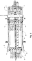
- FIG. 1 shows a partial view of a transfer conveyor 10 according to the invention for the vertical transport of unit load units, with conveyor units 30 of the transfer conveyor. Visible is an upper area of the transfer conveyor, namely the area in a transfer zone 5 in which the transfer to or from an overhead conveyor 80 takes place. Further, a portion of an overhead conveyor 80 is in the transfer zone 5 shown.
- a front half of the transfer conveyor 10 and the overhead conveyor 80 is omitted from the illustration.
- FIG. 3 shows the portion of the overhead conveyor system 80 as viewed from below onto the transfer zone.
- the transfer conveyor 10 includes two parallel drive chains 11 (one of which is visible) circumferentially disposed on a support structure 13 on respective wheels and rollers (not shown). Drive and control, not shown, permit controlled movement of the conveyor units 30 in both possible directions.
- pairs of pivot bearings 15 are mounted in pairs. In these pairs of pivot bearings 15 each have a rotation axis 35 of a conveyor unit 30 is rotatably mounted.
- the rake 31 of the conveyor unit 30 is secured against rotation.
- the rake 31 consists of a plurality of individual, substantially identical prongs 34, which are spaced from each other on the axis of rotation 35 are arranged.
- the tines 34 are angled, so that in combination of all tines two flat walls 32, 33 result, on which rest a piece goods unit or can rest.
- the two walls 32, 33 of the rake 31 form a right angle, which is advantageous for substantially rectangular piece-goods units, but is also functional for other forms of piece goods.
- the axis of rotation 35 of the conveyor units 30 projects beyond the two pivot bearings 15 on the drive chain 11 on both sides.
- a control lever 36 is arranged, with a sliding block 37 in the form of a rotatably mounted wheel.
- the sliding block runs in a backdrop consisting of two guide structures, which form a guide channel of the backdrop between them, wherein in the representation due to the angle only an outer guide structure 14 of the scenes is visible.
- the guide slot 14 allows the orientation of the rake 31 to be determined with respect to the axis of rotation 35, and also absorbs a portion of the weight of the conveyor units and their contents.
- the rake 31 of the conveyor units 30 is aligned so that the walls 32, 33 are aligned parallel to the walls 69, 70 of the conveyor units 60 of the overhead conveyor system 80.
- An inventive conveying unit 60 of the overhead conveyor system comprises in the illustrated embodiment, two carriages 63, 63 ', which in the running rail 81 of Overhead conveyor 80 run.
- the two carriages 63, 63 ' are pivotally connected via first suspensions 65, 65' to a first support structure 64.
- a second support structure 66 which in turn carries the rake 68, is pivotably connected to the first support structure 64 via second suspensions 67, 67 '.
- the rake 68 consists of six prongs 72 in the form of angled U-profiles, which are connected via a transverse strut with the second support structure 66.
- Two walls 69, 70 of the rake 68 are formed from the angle of the tines 72.
- Two side walls 71 are attached laterally to prevent the load from slipping sideways during the optionally rapid transport of a conveyor unit 60 in the overhead conveyor system along a curved conveying path. Next serve the side walls 71 of the attachment of a guide pin 74, which will be discussed below.
- a clamping device 73 which fixes the stored unit-load unit from above during the transport of the conveyor unit 60 in the overhead conveyor system 80. In the FIGS. 2a and 2 B are shown by the said clamping device 73, only the two pivot pins of the suspension of the pivotable clamping device.
- the suspended conveyor system 80 is configured in the embodiment shown as a gravity-driven conveyor system with individually movable conveyor units 60. Coming from the left, the conveying units 60 running on a running rail 81 are gravity-driven and reach the transfer zone of the installation.
- a separating device 82 transfers a conveying unit 60 to a worm drive 83 with a motor 84, which moves the conveying unit 60 to a transfer position and temporarily fixes it in the conveying direction.
- the worm drive 83 has two different helical pitches in front of and behind the transfer position, so that when two conveyor units 60 are replaced, the new second conveyor unit 60 is supplied to the left from further away than it is led away to the right. In this way, the length of the worm drive between the separating mechanism 82 and transfer to the free-running overhead conveyor system can be minimized.
- the transfer position corresponds to the representation of the central conveyor unit 60.
- a guide slot 85 carries two laterally on the rake of the conveyor unit 60 mounted guide pin 74, which fixes the rake 68 in the lateral direction perpendicular to the conveying direction in combination with acting on an upper part of the rake 68 baffles 86 and ensures an exact alignment of the prongs of the rake 68.
- the Guide slot 85 also controls the angle of inclination of the rake 68 pivotally mounted, because the orientation of the suspended rake results from the distance of the guide pin 74 from the track 81.
- the conveyor units 30 of the transfer conveyor 10 move clockwise during the transfer.
- the conveyor unit 30 shown on the left would approach the still unoccupied, temporarily fixed central conveyor unit 60 with a piece goods unit (not shown) lying on the rake 31 and being conveyed to the conveyor unit 60 following the predetermined conveyor path.
- the rake 31 of the conveyor unit 30 then penetrates the rake 68 of the conveyor unit 60, and advantageously so that at the moment of transfer, the tines 34 of the rake 31 and the tines 72 of the rake 68 form a common storage area. Now moves the conveyor unit 30 on, the piece goods unit remains on the rake 68 of the conveyor unit 60 are. The handover of the piece goods unit to the overhead conveyor system has taken place.
- the now loaded conveyor unit 60 is moved to the right, and passed on to the subsequent section of the conveying path of the overhead conveyor system.
- a piece goods unit is to be transferred from a conveyor unit 60 of the overhead conveyor system 80 to the transfer conveyor 10
- the conveyor units 30 of the transfer conveyor 10 move counterclockwise during the transfer.
- the conveying unit 30, which is still unoccupied on the right-hand side, would approach the fixed central conveying unit 60 from the bottom right, following the predetermined conveying path.
- the rake 31 of the conveyor unit 30 then penetrates the rake 68 of the conveyor unit 60, and in turn advantageously so that at the moment of transfer the tines 34 of the rake 31 and the tines 72 of the rake 68 form a common bearing surface. If the conveyor unit 30 now moves on, the piece goods unit previously lying on the rake 68 remains on the rake 31 of the conveyor unit 30 and is conveyed away from it. The handover of the piece goods unit to the transfer conveyor 10 has taken place.
- the rake 31 has reached a position in which the ends of the tines of the rake 68 can no longer collide with the piece goods unit, so when the lowest point of the rake 31 is above the end of the teeth of the rake 68, the now loaded Feed unit 60 are moved to the right. It must be ensured that the conveying path of the overhead conveyor system is free, which can be achieved for example by a suitable choice of the conveying speed of the transfer conveyor 10 and the distance of the successive conveyor units 30.
- the narrow lateral dimensions of the transfer conveyor with substantially vertical conveying of the unit-load units and a transfer at the level of the overhead conveyor system leads to a substantially lower demand for floor space and volume of a system according to the invention, compared to the prior art, where for the loading and unloading of conveyor units of a overhead conveyor system, the conveyor units must first be directed to a different, lower level in order to be brought up again after the charge transfer has taken place. Due to the limited possible pitch angle of the conveying path of a suspension conveyor system while much more floor space and volume is required.
- the system according to the invention also makes it possible to feed both unit load units into a suspended conveyor system and to take unit load units from the overhead conveyor system without constructive adjustments, merely by changing the conveying direction and changing the control of the drive means and actuators ,
- An inventive system can be used as flexible.
- FIGS. 4a to 4i The operation of a system according to the invention is in the FIGS. 4a to 4i explained step by step, using the example of a continuous transfer of cargo units 2, 2 ', 2 "from a suspension conveyor 80 on a transfer conveyor 10, and from there to a further conveyor 90.
- the individual elements are shown only schematically.
- a use case may be, for example, a book production line in which books are printed at a minimum run of only 1 with fast digital printers and provided as folded book blocks to be subsequently envelope-wrapped, trimmed, packaged and shipped in further manufacturing steps.
- a suspended conveyor system can contain buffer zones, printing and post-processing can be decoupled, which allows optimization of the individual production steps without affecting other production steps, but can also compensate for a temporary downtime of individual processing plants.
- Overhead conveyor systems may also include storage subsystems, allowing further optimization of overall system performance. For the various products and intermediates a common overhead conveyor system can be used. For example, book blocks and finished books can be delivered to the right destination via the same suspended conveyor system.
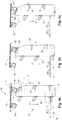
- FIG. 4a shows a first phase of a transfer process.
- a revolving conveyor chain comprises a plurality of first conveyor units, and is supported by guide rollers 12.
- the second conveyor unit 60 "of the overhead conveyor system 80 previously moved to the transfer position from the left in a first transfer zone 5 is loaded with a piece-goods unit 2", in the exemplary application mentioned above, for example a stack of several book blocks, which has been previously fed into the overhead conveyor system , From the bottom right, a first conveyor unit 30 "approaches the transfer conveyor 10 at a steep angle ⁇ .
- the rakes of the first conveyor units 30 '30" are aligned so that the parcel units are securely held at the angle of the two walls of the rake.
- FIG. 4b shows a second phase of a transfer process according to the invention.
- the first conveyor unit 30 "has reached the second conveyor unit 60" fixed at the transfer position.
- the rake of the two conveyor units penetrate each other by meshing, and all tines form a common surface on which the cargo unit 2 "rests.
- Figure 4c shows a third phase of a transfer process according to the invention.
- the first conveyor unit 30 "has lifted the piece goods unit 2" from the second conveyor unit 60 "and guides it to the left.In order to minimize the space requirement in height, the first conveyor unit 30" becomes parallel to the tines of the second conveyor unit The first conveyor unit 30 approaches the first transfer zone 5 and begins to tilt rearwardly from the horizontal due to the control link (not shown).
- FIG. 4d shows a fourth phase of a transfer process according to the invention.
- the first conveyor unit 30 "has now lifted the unit-load unit 2" so far that the second conveyor unit 60 "could be conveyed away without hindrance to the right FIGS. 1 and 3 2, which can move two second conveyer units at the same time, the second conveyer unit 60 "provisionally stops because the conveyance path for the next second conveyance unit 60 to be unloaded is not yet cleared.
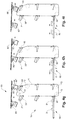
- Figure 4e shows a fifth phase of a transfer process according to the invention.
- the first conveyor unit 30 "begins to descend vertically in the direction of the second transfer zone 6.
- the first conveyor unit 30 ' meanwhile reaches the second transfer zone 6. Because of the correspondingly designed control link (not shown), the rake of the first conveyor unit 30' begins to incline in the direction of the horizontal ,
- FIG. 4f shows a sixth phase of a transfer process according to the invention.
- the rake of the first conveyor unit 30 ' is now aligned horizontally, and penetrates combing the belt conveyor 90 consisting of a plurality of parallel belt conveyors. Before the piece goods unit 2 'reaches the belt conveyor 90, the belt conveyor is temporarily stopped.
- Figure 4g shows a seventh phase of a transfer process according to the invention.
- the first conveying unit 30 "is now so far down that the conveying path for the next second conveying unit 60 to be unloaded is free, which is now moved into the first transfer zone 5, and at the same time the empty second conveying unit 60" becomes out of the first transfer zone 5 moved out.
- the transfer conveyor 10 is temporarily stopped.
- the horizontal conveyor of the first conveyor unit 30 ' has already penetrated the stationary conveyor belt 90 in combing fashion and deposited the unit-load unit 2' on the horizontal belt conveyor 90.
- Figure 4h shows an eighth phase of a transfer process according to the invention.
- the belt conveyor 90 continues to convey, and transports the deposited general cargo unit 2 'from the second transfer zone 6.
- the empty second conveyor unit 60 "has left the first transfer zone 5 and is fed from the overhead conveyor 80 to a new use.
- FIG. 4i shows a ninth phase of a transfer process according to the invention.
- the second conveyor unit 60 has reached the transfer position and is fixed.
- the transfer conveyor 10 starts up again.
- This ninth phase corresponds to the first phase FIG. 4a ,
- the transfer cycle is completed.
- the transfer conveyor 10 stands still while in the phases of the FIGS. 4a to 4f running.
- the conveying speed is reduced in each case to the time of a transfer in order to achieve a gentler transfer or transfer of a piece goods unit, particularly advantageous decreases the conveying speed at the moment of transfer to zero.
- a piece goods unit 2 'supplied by the belt conveyor 90 for example a stack of book blocks from a digital printing press, is ready for takeover in the second transfer zone 6 on the stationary belt conveyor 90 ( Figure 4g ).
- the rake of the first conveyor unit 30 ' is tilted backwards from the horizontal ( Figure 4e ).
- the first conveying unit 30 has reached the first transfer zone 5 and moves from the top left onto the waiting empty second conveying unit 60" ( FIG. 4d . 4c ).
- the first conveyor unit 30 has reached the second conveyor unit 60", and the rakes of the two conveyor units 30 ", 60” form a common storage area on which the parcel unit 2 "lies ( FIG. 4b ).
- the first conveying unit 30 has deposited the piece goods unit 2" on the second conveying unit 60 ", and is further conveyed so far that the conveying path for the now occupied second conveying unit 60" and the next second conveying unit 60 to be filled is free ( FIG. 4a ).
- the transfer conveyor 10 is stopped ( FIG. 4a . 4i ).
- a new general cargo unit is conveyed by the belt conveyor 90 in the second transfer zone 6.
- the occupied second conveyor unit 60 "is carried away from the first transfer zone 5, and a second conveyor unit 60 is supplied ( Figure 4h ).
- the belt conveyor 90 is stopped ( FIGS. 4a . 4h ).
- the transfer conveyor 10 starts up again.
- the transfer cycle starts from the beginning ( Figure 4g ).
Abstract
Eine Anlage zum Transferieren von Stückgut-Einheiten (2, 2', 2") zu und/oder von Fördereinheiten (60, 60") eines schienengeführten Hängefördersystems (80) umfasst mindestens eines Transferfördervorrichtung (10) mit einer oder mehreren ersten Fördereinheiten (30, 30', 30"), wobei die einzelnen ersten Fördereinheiten einen Rechen (31) aufweisen, mit einer Vielzahl von Zinken (34), welche eine Aufnahme (38) zur Lagerung einer Stückgut-Einheit bilden; und ein Hängefördersystem (80) mit einer Mehrzahl von zweiten Fördereinheiten (60, 60"), wobei die einzelnen zweiten Fördereinheiten einen Rechen (68) aufweisen, mit einer Vielzahl von Zinken (72), welche eine Aufnahme (62) zur Lagerung einer Stückgut-Einheit bilden. Die mindestens eine Transferfördervorrichtung und das mindestens eine Hängefördersystem sind derart ausgestaltet, dass in einer Transferzone (5) ein Rechen (31) einer ersten Fördereinheit der Transferfördervorrichtung und ein Rechen (68) einer zweiten Fördereinheit des Hängefördersystems sich kämmend durchdringen, so dass bei einer Bewegung der ersten und der zweiten Fördereinheit relativ zueinander entweder eine zuerst auf dem Rechen der ersten Fördereinheit gelagerte Stückgut-Einheit auf den Rechen der zweiten Fördereinheit liegen bleibt, oder eine zuerst auf dem Rechen der zweiten Fördereinheit gelagerte Stückgut-Einheit auf den Rechen der ersten Fördereinheit liegen bleibt.A system for transferring unit load units (2, 2 ', 2 ") to and / or conveyor units (60, 60") of a rail-mounted overhead conveyor system (80) comprises at least one transfer conveyor (10) with one or more first conveyor units (30 , 30 ', 30 "), wherein the individual first conveyor units have a rake (31), with a plurality of tines (34), which form a receptacle (38) for storing a unit load unit, and a suspended conveyor system (80) a plurality of second conveyor units (60, 60 "), wherein the individual second conveyor units comprise a rake (68), with a plurality of prongs (72), which form a receptacle (62) for storing a parcel unit. The at least one transfer conveyor device and the at least one overhead conveyor system are configured such that in a transfer zone (5) a rake (31) of a first conveyor unit of the transfer conveyor and a rake (68) of a second conveyor unit of the overhead conveyor system intermesh, so that during a movement The first and the second conveyor unit relative to each other either a first stored on the rake of the first conveyor unit cargo unit remains on the rake of the second conveyor unit, or a first stored on the rake of the second conveyor unit cargo unit lie on the rake of the first conveyor unit remains.
Description
Die vorliegende Erfindung bezieht sich auf das Gebiet der Transport- und Fördertechnik. Sie betrifft eine Anlage zum Transferieren von Stückgut-Einheiten zu und/oder von Fördereinheiten eines schienengeführten Hängefördersystems. Sie betrifft weiter eine Fördereinheit für ein Hängefördersystem, und ein Verfahren zum Transferieren von Stückgut-Einheiten zu und/oder von Fördereinheiten eines Hängefördersystems.The present invention relates to the field of transport and conveyor technology. It relates to a system for transferring unit load units to and / or conveyor units of a rail-mounted overhead conveyor system. It further relates to a conveyor unit for a suspended conveyor system, and to a method for transferring unit-load units to and / or conveyor units of a suspended conveyor system.
In automatisierten Warenlagern, weitläufigen Produktionsstätten und ganz allgemein bei der Förderung und dem Transport von Stückgütern haben sich schienengeführte Hängefördersysteme als ein effizientes Mittel für den Transport, die Zwischenpufferung, aber auch die langfristige Lagerung verschiedener Arten von Stückgütern erwiesen. Bei Hängefördersystemen werden die Stückgüter entweder auf geeignete Weise direkt an einzelnen Fördereinheiten eines Fördersystems aufgehängt, oder in entsprechende Aufnahmevorrichtungen eingebracht, die wiederum hängend an den Fördereinheiten gelagert sind.In automated warehouses, large-scale production facilities and, more generally, in the transport and transport of general cargo, rail-mounted overhead conveyor systems have proved to be an efficient means of transport, buffering and long-term storage of various types of general cargo. In suspended conveyor systems, the piece goods are either suspended in a suitable manner directly to individual conveyor units of a conveyor system, or introduced into corresponding receiving devices, which in turn are suspended from the conveyor units.
Unter Stückgütern werden in diesem Zusammenhang allgemein einzeln transportierbare Einheiten verstanden, wie beispielsweise Werkstücke, Halbfabrikate und Fabrikate in Produktionsprozessen, Ersatzteile, Konsumgüter, Stapel von stapelbaren Gütern, beispielsweise Stapel von Druckerzeugnissen, aber auch Behältnisse und Transportträger für Waren, wie beispielsweise Kisten, Behälter, Gepäckstücke, Fässer, Pakete, Paletten, etc.In this context, piece goods are generally understood as individually transportable units, such as workpieces, semifinished products and products in production processes, spare parts, consumer goods, stacks of stackable goods, for example stacks of printed products, but also containers and transport carriers for goods, such as boxes, containers, Luggage, barrels, packages, pallets, etc.
Schienengeführte Hängefördersysteme können als Kettenfördereranlagen realisiert sein, bei welchen eine Vielzahl von Fördereinheiten, welche Glieder einer Kette bilden, entlang eines Förderwegs bewegt wird.Rail-mounted overhead conveyor systems may be implemented as chain conveyor systems in which a plurality of conveyor units forming links of a chain are moved along a conveyor path.
Schienengeführte Hängefördersysteme mit einzeln förderbaren Transporteinheiten sind ebenfalls bekannt. So zeigt beispielsweise die
Hängefördersysteme erlauben es, einen Grossteil des Fördersystems über Kopf an der Decke zu montieren, so dass die Grundfläche frei bleibt für Fertigungsanlagen und andere Einrichtungen. Für die Einspeicherung, Ausspeicherung oder Bearbeitung von Gütern muss der Förderpfad jedoch auf ein tieferes Niveau gebracht bzw. wieder nach oben geführt werden, was wegen der eingeschränkten Steigungswinkel von schienengeführten Hängefördersystemen einiges an Grundfläche und Raumvolumen benötigt, die anderweitig genutzt werden könnten.Overhead conveyor systems allow a large part of the conveyor system to be mounted overhead on the ceiling so that the floor space remains free for production facilities and other equipment. However, for the storage, withdrawal or processing of goods, the conveying path must be brought to a lower level or brought back upwards, which requires a lot of floor space and volume due to the limited slope angle of rail-mounted overhead conveyor systems, which could be used elsewhere.
Hängefördersysteme mit Transporteinheiten sind besonders geeignet für die effiziente Förderung von heterogenen Stückgütern. So können beispielsweise in Logistikzentren von Versandhandelsfirmen solche Hängefördersysteme verwendet werden, um eine Vielzahl von Artikeln verschiedener Grösse und Gewicht einzulagern, und Gruppen von Artikeln gemäss den jeweiligen Kundenaufträgen zu kommissionieren und für den Versand bereitzustellen. Ein anderer Anwendungsbereich ist die Förderung und Speicherung von Zwischenprodukten und/oder Endprodukten in Druckproduktionsprozessen.Overhead conveyor systems with transport units are particularly suitable for the efficient transport of heterogeneous general cargo. For example, in logistics centers of mail-order companies, such overhead conveyor systems can be used to store a variety of articles of various sizes and weights, and to pick and deliver groups of articles according to the individual customer orders. Another area of application is the promotion and storage of intermediates and / or end products in print production processes.
Ein für ein Hängefördersystem relevanter Aspekt ist dabei das einfache, reibungslose und effiziente Einbringen von Stückgütern in leere Transporteinheiten und Entnehmen der Stückgüter aus dem Transporteinheiten, aber auch ein effizienter Transfer zwischen verschiedenen Fördersystemen, und ein geringer Bedarf an Raumvolumen und Grundfläche.An aspect that is relevant for a suspended conveyor system is the simple, smooth and efficient introduction of piece goods into empty transport units and removal of the piece goods from the transport units, but also an efficient transfer between different conveyor systems, and a low requirement for volume and floor area.
Die oben genannten Vorrichtungen benötigen eine Vielzahl aufwendiger angetriebener bzw. bewegter Zuführ- und Abführvorrichtungen. Eine Übergabe der Stückgüter ist nur auf Bandförderer-basierte Fördersysteme oder Förderfahrzeuge möglich.The above-mentioned devices require a large number of complex driven or moving feed and discharge devices. A transfer of the piece goods is only possible on belt conveyor systems or conveyor vehicles.
Es besteht allgemein das Bedürfnis nach Fortschritten in diesem Gebiet der Technik.There is a general need for advances in this field of technology.
Aufgabe der Erfindung ist es, eine Anlage zum Transferieren von Stückgut-Einheiten zu und/oder von Fördereinheiten eines schienengeführten Hängefördersystems zur Verfügung zu stellen, welche die oben erwähnten und andere Nachteile nicht aufweist. Insbesondere soll eine solche Anlage eine effiziente Übergabe von Stückgütern an schienengeführte Hängefördersysteme ermöglichen, bzw. eine effiziente Übernahme von Stückgütern aus schienengeführten Hängefördersystemen.The object of the invention is to provide a system for transferring unit load units to and / or conveyor units of a rail-mounted overhead conveyor system which does not have the above-mentioned and other disadvantages. In particular, such a system should enable an efficient transfer of piece goods to rail-mounted overhead conveyor systems, or an efficient takeover of piece goods from rail-mounted overhead conveyor systems.
Eine weitere Aufgabe der Erfindung ist es, eine vorteilhafte Fördereinheit für ein Hängefördersystem zur Verfügung zu stellen, die insbesondere in einer erfindungsgemässen Anlage eingesetzt werden kann;Another object of the invention is to provide an advantageous conveyor unit for a suspended conveyor system, which can be used in particular in a system according to the invention;
Noch eine andere Aufgabe der Erfindung ist es, ein vorteilhaftes Verfahren zum Transferieren von Stückgut-Einheiten zu und/oder von Fördereinheiten eines Hängefördersystems zur Verfügung zu stellen, welches eine effiziente Übergabe von Stückgütern an Hängefördersysteme ermöglichen, bzw. eine effiziente Übernahme von Stückgütern aus Hängefördersystemen ermöglicht.Yet another object of the invention is to provide an advantageous method for transferring unit load units to and / or conveyor units of a suspension conveyor system, which enable an efficient transfer of piece goods to overhead conveyor systems, or an efficient takeover of piece goods from overhead conveyor systems allows.
Diese und andere Aufgaben werden gelöst durch eine erfindungsgemässe Anlage zum Transferieren von Stückgut-Einheiten zu und/oder von Fördereinheiten eines schienengeführten Hängefördersystems, eine erfindungsgemässe Fördereinheit für ein schienengeführtes Hängefördersystem, und ein Verfahren zum Transferieren von Stückgut-Einheiten zu und/oder von Fördereinheiten eines schienengeführten Hängefördersystems, gemäss den unabhängigen Ansprüchen. Weitere vorteilhafte Ausführungsformen sind in den abhängigen Ansprüchen gegeben.These and other objects are achieved by a system according to the invention for transferring unit load units to and / or from conveyor units of a rail-mounted overhead conveyor system, a conveyor unit according to the invention for a rail-guided overhead conveyor system, and a method for transferring unit-load units to and / or conveyor units of one Rail-mounted overhead conveyor system according to the independent claims. Further advantageous embodiments are given in the dependent claims.
Die erfindungsgemässe Lösung kann durch verschiedene, jeweils für sich vorteilhafte und, sofern nicht anders ausgeführt, beliebig miteinander kombinierbare Ausgestaltungen weiter verbessert werden. Auf diese Ausführungsformen und die mit ihnen verbundenen Vorteile wird im Folgenden eingegangen.The solution according to the invention can be further improved by various configurations which are advantageous in each case and, if not stated otherwise, can be combined with one another as desired. These embodiments and the advantages associated with them will be discussed below.
Ein erster Aspekt der Offenbarung betrifft eine Anlage zum Transferieren von Stückgut-Einheiten zu und/oder von Fördereinheiten eines schienengeführten Hängefördersystems, insbesondere eines einzelwagen-basierten Hängefördersystems oder eines Förderkettensystems.A first aspect of the disclosure relates to a system for transferring unit load units to and / or conveyor units of a rail-guided overhead conveyor system, in particular a single-carriage-based overhead conveyor system or a conveyor chain system.
Eine erfindungsgemässe Anlage zum Transferieren von Stückgut-Einheiten zu und/oder von Fördereinheiten eines schienengeführten Hängefördersystems umfasst mindestens eine Transferfördervorrichtung mit einer oder mehreren ersten Fördereinheiten, wobei die einzelnen ersten Fördereinheiten einen Rechen aufweisen, mit einer Vielzahl von Zinken, welche eine Aufnahme zur Lagerung einer Stückgut-Einheit bilden; und ein Hängefördersystem mit einer Mehrzahl von zweiten Fördereinheiten, wobei die einzelnen zweiten Fördereinheiten einen Rechen aufweisen, mit einer Vielzahl von Zinken, welche eine Aufnahme zur Lagerung einer Stückgut-Einheit bilden. Die mindestens eine Transferfördervorrichtung und das Hängefördersystem sind derart ausgestaltet, dass in einer Transferzone ein Rechen einer ersten Fördereinheit der Transferfördervorrichtung und ein Rechen einer zweiten Fördereinheit des Hängefördersystems sich kämmend durchdringen, so dass bei einer Bewegung der ersten und der zweiten Fördereinheit relativ zueinander entweder eine zuerst auf dem Rechen der ersten Fördereinheit gelagerte Stückgut-Einheit auf den Rechen der zweiten Fördereinheit liegen bleibt, oder eine zuerst auf dem Rechen der zweiten Fördereinheit gelagerte Stückgut-Einheit auf den Rechen der ersten Fördereinheit liegen bleibt.A system according to the invention for transferring unit load units to and / or conveyor units of a rail-mounted overhead conveyor system comprises at least one transfer conveyor with one or more first conveyor units, wherein the individual first conveyor units have a rake, with a plurality of tines, which has a receptacle for storing a Form general cargo unit; and an overhead conveyor system having a plurality of second conveyor units, the individual second conveyor units having a rake with a plurality of tines forming a receptacle for storing a general cargo unit. The at least one transfer conveyor and the overhead conveyor system are configured such that in a transfer zone, a rake of a first conveyor unit of the transfer conveyor and a rake of a second conveyor unit of the overhead conveyor system intermesh, so that upon movement of the first and the second conveyor unit relative to each other either a first stored on the rake of the first conveyor unit unit remains on the rake of the second conveyor unit, or a first stored on the rake of the second conveyor unit cargo unit remains lying on the rake of the first conveyor unit.
Die Aufnahme der ersten Fördereinheiten und/oder die Aufnahme der zweiten Fördereinheiten kann als mindestens eine Wand oder als Mulde ausgestaltet sein.The recording of the first conveyor units and / or the inclusion of the second conveyor units can be configured as at least one wall or as a trough.
Die Rechen der ersten Fördereinheiten können beispielsweise fünf einzelne Zinken aufweisen. Die Anzahl Zinken kann jedoch auch kleiner sein, minimal zwei, oder grösser, wobei sich die Anzahl aus der konkreten Dimensionierung der Anlage, beispielsweise der Breite der Fördereinheiten, aus den damit zusammenwirkenden Fördereinheiten eines Hängefördersystems, aber auch aus der Art der zu transportierenden Stückgut-Einheiten ergibt.The rakes of the first conveyor units may, for example, have five individual prongs. However, the number of tines can also be smaller, minimum two, or larger, with the number of the concrete dimensioning of the system, for example, the width of the conveyor units, from the cooperating conveyor units of a suspension conveyor system, but also from the nature of the transportable Stückgut- Units results.
In einer erfindungsgemässen Anlage sind vorteilhaft die zweiten Fördereinheiten des Hängefördersystems einzeln förderbar, unabhängig von anderen zweiten Fördereinheiten.In a system according to the invention, the second conveyor units of the overhead conveyor system can advantageously be conveyed individually, independently of other second conveyor units.
Vorteilhaft bewegen sich in einer erfindungsgemässen Anlage die ersten Fördereinheiten entlang einem geschlossenen Förderpfad, wobei ein Abschnitt dieses Förderpfads der Transferzone entspricht.Advantageously, in a system according to the invention, the first conveyor units move along a closed conveyor path, wherein a section of this conveyor path corresponds to the transfer zone.
Alternativ oder zusätzlich können sich die ersten Fördereinheiten auf einem Förderpfad zwischen der Transferzone und mindestens einer weiteren Zone bewegen.Alternatively or additionally, the first conveyor units can move on a conveying path between the transfer zone and at least one further zone.
In einer vorteilhaften Variante einer solchen erfindungsgemässen Anlage verläuft in der Transferzone der Förderpfad der ersten Fördereinheiten und der Förderpfad der zweiten Fördereinheiten in einer Ebene. Besonders vorteilhaft verläuft in der Transferzone der Förderpfad der ersten Fördereinheiten und der Förderpfad der zweiten Fördereinheiten in einer gemeinsamen Ebene.In an advantageous variant of such a system according to the invention, the conveying path of the first conveying units and the conveying path of the second conveying units extend in a plane in the transfer zone. Particularly advantageously, in the transfer zone, the conveying path of the first conveying units and the conveying path of the second conveying units extend in a common plane.
In einer vorteilhaften Ausführungsform einer erfindungsgemässen Anlage weist die mindestens eine Transferfördervorrichtung Mittel auf, um die Ausrichtung des Rechens einer ersten Fördereinheit in Bezug zur Senkrechten zu verändern.In an advantageous embodiment of a system according to the invention, the at least one transfer conveyor device has means for changing the orientation of the rake of a first conveyor unit with respect to the vertical.
In einer anderen vorteilhaften Ausführungsform einer erfindungsgemässen Anlage weist die mindestens eine Transferfördervorrichtung Mittel auf, um die Ausrichtung des Rechens einer ersten Fördereinheit zu steuern. Besonders vorteilhaft wird dabei die Ausrichtung des Rechens in Abhängigkeit von der Lage der ersten Fördereinheit auf dem Förderpfad gesteuert.In another advantageous embodiment of a system according to the invention, the at least one transfer conveyor device has means for controlling the orientation of the rake of a first conveyor unit. In this case, the orientation of the rake in dependence on the position of the first conveyor unit on the conveying path is controlled particularly advantageously.
In einer weiteren vorteilhaften Ausführungsform einer erfindungsgemässen Anlage sind die Zinken des Rechens einer ersten Fördereinheit auf einer Drehachse der ersten Fördereinheit verdrehsicher angeordnet; und die Transferfördervorrichtung weist zwei parallel geführte geschlossene Antriebsketten auf, auf welchen paarweise gegenüberliegend Drehlager angeordnet sind, in denen jeweils die Drehachse einer Fördereinheit drehbar gelagert ist. Besonders vorteilhaft weisen bei einer solchen Ausführungsform die ersten Fördereinheiten der mindestens einen Transferfördervorrichtung an einem oder beiden Enden der Drehachse einen mit der Drehachse wirkverbundenen Steuerhebel auf, welcher mit Steuermitteln der Transferfördervorrichtung wechselwirkt. Beispielsweise kann eine Kulissenführung oder ein Aktuator verwendet werden, um die Ausrichtung des Rechens der ersten Fördereinheiten zu steuern.In a further advantageous embodiment of a system according to the invention, the prongs of the rake of a first conveyor unit are arranged secured against rotation on an axis of rotation of the first conveyor unit; and the transfer conveyor has two parallel Guided closed drive chains on which are arranged in pairs opposite pivot bearing, in each of which the axis of rotation of a conveyor unit is rotatably mounted. In such an embodiment, the first conveyor units of the at least one transfer conveyor device particularly advantageously have at one or both ends of the axis of rotation a control lever operatively connected to the axis of rotation, which interacts with control means of the transfer conveyor. For example, a slotted guide or an actuator may be used to control the orientation of the rake of the first conveyor units.
In der Transferzone wird der Rechen der ersten Fördereinheiten vorteilhaft so ausgerichtet, dass die Wände des Rechens parallel ausgerichtet sind zu den Wänden der zweiten Fördereinheiten des Hängefördersystems. In einem anderen Bereich des Förderpfads der Transferfördervorrichtung können die Rechen durch beispielsweise eine entsprechende Positionierung einer Führungskulisse so ausgerichtet sein, dass eine Wand waagrecht ausgerichtet ist, um so eine Stückgut-Einheit von einem waagrechten Bandförderer übernehmen oder an einen waagrechten Bandförderer übergeben zu können. Möglich ist auch eine aktive Steuerung der Ausrichtung der Rechen, indem beispielsweise Aktuatoren vorgesehen sind, welche eine Führungskulisse bei Bedarf verändern, beispielsweise durch Verschieben der Führungskulisse.In the transfer zone, the rake of the first conveyor units is advantageously oriented so that the walls of the rake are aligned parallel to the walls of the second conveyor units of the overhead conveyor system. In another area of the conveying path of the transfer conveyor, the rakes can be aligned by, for example, a corresponding positioning of a guide slot so that a wall is aligned horizontally so as to take a piece-unit from a horizontal belt conveyor or handed over to a horizontal belt conveyor. Also possible is an active control of the orientation of the rake by, for example, actuators are provided which change a guide slot if necessary, for example by moving the guide slot.
Das Hängefördersystem einer erfindungsgemässen Anlage kann Mittel aufweisen, um die Ausrichtung des Rechens einer zweiten Fördereinheit in Bezug zur Senkrechten zu verändern.The suspended conveyor system of a system according to the invention can have means for changing the orientation of the rake of a second conveyor unit with respect to the vertical.
Das Hängefördersystem einer erfindungsgemässen Anlage kann weiter Mittel aufweisen, um die Ausrichtung des Rechens einer zweiten Fördereinheit zu steuern. Vorteilhaft erfolgt die Steuerung der Ausrichtung des Rechens in Abhängigkeit von der Lage der zweiten Fördereinheit auf dem Förderpfad.The suspended conveyor system of a system according to the invention may further comprise means for controlling the orientation of the rake of a second conveyor unit. Advantageously, the control of the orientation of the rake in dependence on the position of the second conveyor unit takes place on the conveying path.
In noch einer weiteren vorteilhaften Ausführungsform einer erfindungsgemässen Anlage weisen die zweiten Fördereinheiten des Hängefördersystems Mittel zum klemmenden Halten einer darin gelagerten Stückgut-Einheit auf. Besonders vorteilhaft weist das Hängefördersystem Mittel zum Verriegeln und Entriegeln der Mittel zum klemmenden Halten auf.In yet another advantageous embodiment of a system according to the invention, the second conveyor units of the overhead conveyor system have means for clamping holding a unit-load unit mounted therein. Particularly advantageously, the overhead conveyor system has means for locking and unlocking the means for clamping holding.
Das Hängefördersystem einer erfindungsgemässen Anlage kann Mittel aufweisen, welche in einer Transferzone des Förderpfads der zweiten Fördereinheiten die Ausrichtung der zweiten Fördereinheiten in Bezug auf den Förderpfad fixieren. Dies erlaubt während des Transfers der Stückgut-Einheit eine exakte Ausrichtung der beiden Fördereinheiten zueinander.The overhead conveyor system of a system according to the invention may comprise means which in a transfer zone of the conveying path of the second conveyor units, the orientation fix the second conveyor units with respect to the conveyor path. This allows during the transfer of cargo unit an exact alignment of the two conveyor units to each other.
In einer vorteilhaften Variante einer erfindungsgemässen Anlage bilden die Zinken der Rechen der ersten Fördereinheiten und/oder die Zinken der Rechen der zweiten Fördereinheiten jeweils eine erste Wand und eine zweite Wand aus, die in einem Winkel < 180° zueinander stehen.In an advantageous variant of a system according to the invention, the tines of the rakes of the first conveyor units and / or the tines of the rakes of the second conveyor units each form a first wall and a second wall which are at an angle <180 ° to one another.
Der Winkel beträgt vorteilhaft 90° oder mehr, um ein Verklemmen von im Rechen gelagerten Stückgut-Einheiten zu vermeiden. Für Stückgüter mit speziellen Formgebungen, beispielsweise Kugeln oder Zylindern, können die Zinken so ausgestaltet sein, dass sich in Kombination eine nicht ebene Lagerfläche bildet, beispielsweise eine Mulde in der Form des zu transportierenden Stückgut-Typs, oder ein gerundeter Übergang zwischen den zwei Wänden.The angle is advantageously 90 ° or more to avoid jamming stored in the rake general cargo units. For piece goods with special shapes, such as balls or cylinders, the tines can be designed so that in combination forms a non-planar bearing surface, such as a trough in the form of the cargo type to be transported, or a rounded transition between the two walls.
Die Zinken der ersten Fördereinheiten und/oder der zweiten Fördereinheiten können beispielsweise als Metallelemente, beispielsweise Metallbleche, ausgebildet sein, womit sich die Lagerfläche des Rechens aus der Gesamtheit der Kanten ergibt. Es können auch zusätzliche flächige Elemente vorgesehen sein, beispielsweise Blechstreifen oder Kantenwülste, welche die Auflagefläche erhöhen. Die Zinken können auf der Seite der Lagerflächen eben sein, oder eine Struktur aufweisen, welche beispielsweise die Haftung erhöht. Ebenso kann die Haftreibung erniedrigt sein, beispielsweise durch Gleitflächen aus HDPE oder PTFE. Ebenfalls möglich ist die Anordnung von Rollen mit einer auf den Lagerflächen der Zinken. Die Zinken können auch selber als entlang einer Zinkenachse drehende Längsrollen ausgestaltet sein. Die vorgenannten Rollen können freidrehend und/oder angetrieben sein. Alternativ können die Zinken auch jeweils einen schmalen Riemenförderer umfassen.The tines of the first conveyor units and / or the second conveyor units can be designed, for example, as metal elements, for example metal sheets, with which the bearing surface of the rake results from the entirety of the edges. It can also be provided additional sheet-like elements, such as metal strips or Kantenwülste, which increase the support surface. The tines can be flat on the side of the bearing surfaces, or have a structure which, for example, increases the adhesion. Likewise, the static friction can be lowered, for example by sliding surfaces made of HDPE or PTFE. Also possible is the arrangement of rollers with a on the bearing surfaces of the tines. The tines can also be configured as longitudinal rollers rotating along a tine axis. The aforementioned rollers may be free-rotating and / or driven. Alternatively, the tines may each include a narrow belt conveyor.
Vorteilhaft ist die mindestens eine Transferfördervorrichtung so ausgestaltet, dass in mindestens einem Bereich der Förderpfade der ersten Fördereinheiten und der zweiten Fördereinheiten die erste Wand des Rechens einer ersten Fördereinheit parallel zur ersten Wand des Rechens einer zweiten Fördereinheit steht. Besonders vorteilhaft liegt der genannte mindestens eine Bereich der Förderpfade der ersten Fördereinheiten und der zweiten Fördereinheiten in einer Transferzone der erfindungsgemässen Anlage.Advantageously, the at least one transfer conveyor device is configured such that in at least one region of the conveying paths of the first conveyor units and the second conveyor units the first wall of the rake of a first conveyor unit is parallel to the first wall of the rake of a second conveyor unit. Particularly advantageously, said at least one region of the conveying paths of the first conveying units and of the second conveying units lies in a transfer zone of the installation according to the invention.
In einer erfindungsgemässen Anlage ist vorteilhaft die mindestens eine Transferfördervorrichtung so ausgestaltet, dass an mindestens einem Punkt des Förderpfads der ersten Fördereinheiten die erste Wand des Rechens einer ersten Fördereinheit waagrecht steht.In a system according to the invention, the at least one transfer conveyor device is advantageously designed such that the first wall of the rake of a first conveyor unit is horizontal at at least one point of the conveying path of the first conveyor units.
In einer vorteilhaften Ausführungsvariante einer erfindungsgemässen Anlage ist eine weitere Fördervorrichtung vorgesehen, die an einem der Transferfördervorrichtung zugewandten Ende aus mehreren parallel laufenden Riemenförderern oder einem Rollenförderer mit beabstandeten parallelen Rollen gebildet ist, die sich im Förderpfad der ersten Fördereinheit befinden, und mit den Rechen der ersten Fördereinheiten kämmend wechselwirken, so dass wenn eine erste Fördereinheit die weitere Fördervorrichtung passiert, der Rechen der ersten Fördereinheit die parallel laufenden Riemenförderer bzw. die beabstandeten parallelen Rollen des Rollenförderers der genannten weiteren Fördervorrichtung kämmend durchdringt.In an advantageous embodiment of a system according to the invention, a further conveying device is provided, which is formed at an end facing the transfer conveyor of several parallel belt conveyors or a roller conveyor with spaced parallel rollers, which are located in the conveying path of the first conveyor unit, and with the rake of the first Interacting conveyor units interact so that when a first conveyor unit passes through the further conveyor, the rake of the first conveyor unit penetrates the parallel running belt conveyor or the spaced parallel rollers of the roller conveyor of said further conveyor device.
Ein zweiter Aspekt der Offenbarung betrifft eine Transferfördervorrichtung zum vertikalen Transport von Stückgut-Einheiten zwischen einer ersten Zone und einer darunterliegenden mindestens einer zweiten Zone. Eine solche Transferfördervorrichtung kann vorteilhaft insbesondere in einer erfindungsgemässen Anlage, wie sie oben diskutiert worden ist, eingesetzt werden.A second aspect of the disclosure relates to a transfer conveyor for vertically transporting unit load units between a first zone and an underlying at least one second zone. Such a transfer conveyor can advantageously be used in particular in a system according to the invention, as has been discussed above.
Eine solche vorteilhafte Transferfördervorrichtung zum vertikalen Transport von Stückgut-Einheiten zwischen einer ersten Zone und einer darunterliegenden mindestens einen zweiten Zone weist eine oder mehrere Fördereinheiten auf, wobei die einzelnen Fördereinheiten einen Rechen aufweisen, mit einer Vielzahl von Zinken, welche zur Lagerung einer Stückguteinheit mindestens erste Wand und eine zweite Wand ausbilden, die in einem Winkeln < 180° zueinander stehen, insbesondere einem rechten Winkel oder einem stumpfen Winkel.Such an advantageous transfer conveyor device for the vertical transport of piece goods units between a first zone and an underlying at least one second zone has one or more conveyor units, wherein the individual conveyor units have a rake, with a plurality of tines, which for storage of a unit load unit at least first Form wall and a second wall, which are at an angle <180 ° to each other, in particular a right angle or an obtuse angle.
Vorteilhaft bewegen sich bei einer solchen Transferfördervorrichtung die Fördereinheiten entlang einem geschlossenen Förderpfad, wobei bestimmte Abschnitte des Förderpfads den verschiedenen Zonen entsprechen.Advantageously, in such a transfer conveyor, the conveyor units move along a closed conveyor path, with certain sections of the conveyor path corresponding to the different zones.
Alternativ oder zusätzlich können sich die Fördereinheiten auf einem Förderpfad zwischen der ersten Zone und mindestens einer weiteren zweiten Zone bewegen.Alternatively or additionally, the conveyor units can move on a conveying path between the first zone and at least one further second zone.
In einer solchen Transferfördervorrichtung sind vorteilhaft Mittel vorgesehen, um die Ausrichtung des Rechens einer Fördereinheit in Bezug zur Senkrechten zu verändern.In such a transfer conveyor means are advantageously provided to change the orientation of the rake of a conveyor unit with respect to the vertical.
Vorteilhaft können bei einer solchen Transferfördervorrichtung auch Mittel vorgesehen sein, um die Ausrichtung des Rechens einer Fördereinheit zu steuern, besonders vorteilhaft in Abhängigkeit von der Lage auf dem Förderpfad.Advantageously, in such a transfer conveyor means may be provided to control the orientation of the rake a conveyor unit, particularly advantageous depending on the location on the conveyor path.
Die Zinken des Rechens einer Fördereinheit einer Transferfördervorrichtung sind vorteilhaft auf einer Drehachse der Fördereinheit verdrehsicher angeordnet; und die Vorrichtung weist zwei parallel geführte geschlossene Antriebsketten auf, auf welchen paarweise gegenüberliegend Drehlager angeordnet sind, in denen jeweils die Drehachse einer Fördereinheit drehbar gelagert ist.The prongs of the rake of a conveyor unit of a transfer conveyor are advantageously arranged against rotation on a rotation axis of the conveyor unit; and the device has two parallel closed drive chains, on which pairs opposite pivot bearings are arranged, in each of which the axis of rotation of a conveyor unit is rotatably mounted.
Besonders vorteilhaft weisen dabei die Fördereinheiten an einem oder beiden Enden der Drehachse einen mit der Drehachse wirkverbundenen Steuerhebel auf, welcher mit Steuermitteln der Transferfördervorrichtung wechselwirkt, beispielsweise einer Kulissenführung oder einem Aktuator, um so die Ausrichtung des Rechens zu steuern.In this case, the conveyor units at one or both ends of the axis of rotation particularly advantageously have a control lever operatively connected to the rotation axis, which interacts with control means of the transfer conveyor, for example a slotted guide or an actuator so as to control the orientation of the rake.
Ein dritter Aspekt der Offenbarung betrifft eine Fördereinheit für ein schienengeführtes Hängefördersystem, insbesondere ein einzelwagen-basierten Hängefördersystems oder ein Förderkettensystem.A third aspect of the disclosure relates to a conveyor unit for a rail-guided overhead conveyor system, in particular a single-carriage-based overhead conveyor system or a conveyor chain system.
Eine erfindungsgemässe Fördereinheit für ein schienengeführtes Hängefördersystem umfasst eine Tragstruktur und einen Rechen zum Transport einer zu fördernden Stückgut-Einheit, umfassend eine Vielzahl von Zinken, welche eine Aufnahme zur Lagerung der zu fördernden Stückgut-Einheit ausbilden, wobei die Fördereinheit Mittel zum klemmenden Halten einer in der Aufnahme geförderten Stückgut-Einheit aufweist.A conveying unit according to the invention for a rail-guided suspended conveyor system comprises a supporting structure and a rake for transporting a piece goods unit to be conveyed, comprising a plurality of tines, which form a receptacle for supporting the piece goods unit to be conveyed, wherein the conveying unit comprises means for clamping holding a in the receiving subsidized cargo unit has.
Die Aufnahme kann als mindestens eine ebene Wand ausgebildet sein, oder als Mulde.The receptacle may be formed as at least one flat wall, or as a trough.
In einer vorteilhaften Ausführungsform einer erfindungsgemässen Fördereinheit bilden die Zinken des Rechens eine erste Wand und eine zweite Wand aus, die in einem Winkel < 180° zueinander stehen, insbesondere einem rechten Winkel oder einem stumpfen Winkel.In an advantageous embodiment of a conveyor unit according to the invention, the tines of the rake form a first wall and a second wall which are at an angle <180 ° to one another, in particular a right angle or an obtuse angle.
Ein vierter Aspekt der Offenbarung betrifft Verfahren zum Transferieren von Stückgut-Einheiten zu und/oder von Fördereinheiten eines schienengeführten Hängefördersystems, insbesondere eines einzelwagen-basierten Hängefördersystems oder eines Förderkettensystems.A fourth aspect of the disclosure relates to methods for transferring unit load units to and / or conveyor units of a rail-mounted overhead conveyor system, in particular a single-car-based overhead conveyor system or a conveyor chain system.
Ein erfindungsgemässes Verfahren zum Transferieren von Stückgut-Einheiten zu und/oder von Fördereinheiten eines schienengeführten Hängefördersystems umfasst die Schritte:
- Bereitstellen einer erfindungsgemässen Transferanlage wie obenstehend erläutert;
- Positionieren einer zweiten Fördereinheit des Hängefördersystems in einer Transferzone des Förderpfads der zweiten Fördereinheiten;
- Heranführen einer ersten Fördereinheit der Transferfördervorrichtung in eine Transferzone des Förderpfads der ersten Fördereinheiten; und
- kämmendes gegenseitiges Durchdringen des Rechens der ersten Fördereinheit und des Rechens der zweiten Fördereinheit;
- Providing a transfer system according to the invention as explained above;
- Positioning a second conveyor unit of the overhead conveyor system in a transfer zone of the conveyor path of the second conveyor units;
- Bringing a first conveying unit of the transfer conveyor into a transfer zone of the conveying path of the first conveying units; and
- intermeshing mutual penetration of the rake of the first conveyor unit and the rake of the second conveyor unit;
In einem erfindungsgemässen Verfahren wird vorteilhaft eine zweite Fördereinheit erst dann in die Transferzone und/oder aus der Transferzone gebracht, wenn sich die ersten Fördereinheiten in einer Position befinden, in welcher keine Kollision mit einer der zweiten Fördereinheiten des Hängefördersystems möglich ist.In a method according to the invention, a second conveyor unit is advantageously brought into the transfer zone and / or out of the transfer zone only when the first conveyor units are in a position in which no collision with one of the second conveyor units of the overhead conveyor system is possible.
In einer vorteilhaften Variante eines erfindungsgemässen Verfahrens bleiben die ersten Fördereinheiten der Transferfördervorrichtung nach der Übernahme einer Stückgut-Einheit von der zweiten Fördereinheit oder der Übergabe der Stückgut-Einheit an die zweite Fördereinheit in einer sicheren Position stehen, in welcher keine Kollision mit der genannten zweiten Fördereinheit möglich ist. Die genannte zweite Fördereinheit wird dann aus der Transferzone weggeführt.In an advantageous variant of a method according to the invention, the first conveyor units of the transfer conveyor device remain after taking over a piece goods unit from the second conveyor unit or the transfer of the piece goods unit to the second Be conveyor unit in a safe position, in which no collision with said second conveyor unit is possible. The said second conveyor unit is then led away from the transfer zone.
In einer weiteren vorteilhaften Variante eines erfindungsgemässen Verfahrens bleiben die ersten Fördereinheiten der Transferfördervorrichtung vor dem Zuführen einer zweiten Fördereinheit in die Transferzone in einer sicheren Position stehen, in welcher keine Kollision mit der genannten zweiten Fördereinheit möglich ist.In a further advantageous variant of a method according to the invention, the first conveyor units of the transfer conveyor device remain in a secure position before feeding a second conveyor unit into the transfer zone, in which no collision with said second conveyor unit is possible.
In einer möglichen vorteilhaften Variante des erfindungsgemässen Verfahrens wird während des Transfers einer Stückgut-Einheit die zweite Fördereinheit in der Transferzone nicht bewegt. Die hat den Vorteil, dass durch vorübergehende räumliche Fixierung der zweiten Fördereinheit auf einfache und verlässliche Weise die präzise relative Orientierung der ersten Fördereinheit und der zweiten Fördereinheit während des Transfers erreicht werden kann.In a possible advantageous variant of the method according to the invention, the second conveyor unit is not moved in the transfer zone during the transfer of a unit load unit. This has the advantage that the precise relative orientation of the first conveyor unit and the second conveyor unit during the transfer can be achieved by temporary spatial fixation of the second conveyor unit in a simple and reliable manner.
In einer anderen möglichen vorteilhaften Variante des erfindungsgemässen Verfahrens bewegt sich während des Transfers einer Stückgut-Einheit auch die zweite Fördereinheit in Förderrichtung entlang ihres Förderpfads in der Transferzone. Eine solche Variante erlaubt schnellere Taktraten, da die zweiten Fördereinheiten nicht angehalten werden müssen. Um eine präzise relative Orientierung der ersten Fördereinheit und der zweiten Fördereinheit während des Transfers sicherzustellen, müssen die Bewegungen der beiden Fördereinheiten genau gesteuert werden, was höhere Anforderungen an die Steuerung stellt.In another possible advantageous variant of the method according to the invention, during the transfer of a unit load unit, the second conveyor unit also moves along its conveying path in the transfer zone in the conveying direction. Such a variant allows faster clock rates, since the second conveyor units do not need to be stopped. To ensure a precise relative orientation of the first conveyor unit and the second conveyor unit during the transfer, the movements of the two conveyor units must be precisely controlled, which makes higher demands on the controller.
In einer besonders vorteilhaften Variante des vorgenannten erfindungsgemässen Verfahrens bewegen sich während des Transfers einer Stückgut-Einheit die zweite Fördereinheit und die erste Fördereinheit in einer gemeinsamen Förderrichtung, wobei die übernehmende Fördereinheit die übergebende Fördereinheit überholt. Eine solche Variante erlaubt einen Transfer bei höherer Fördergeschwindigkeit der zweiten Fördereinheiten, da die relativen Geschwindigkeitsunterschiede zwischen erster Fördereinheit und zweiter Fördereinheit gering sind.In a particularly advantageous variant of the abovementioned method according to the invention, during the transfer of a unit load unit, the second conveyor unit and the first conveyor unit move in a common conveying direction, wherein the receiving conveyor unit overtakes the transfer unit being transferred. Such a variant allows a transfer at a higher conveying speed of the second conveyor units, since the relative speed differences between the first conveyor unit and the second conveyor unit are small.
Zum besseren Verständnis der vorliegenden Erfindung wird nachfolgend auf die Zeichnungen Bezug genommen. Diese zeigen lediglich Ausführungsbeispiele des Erfindungsgegenstands, die nicht dazu geeignet sind, die Erfindung auf die hierin offenbarten Merkmale zu beschränken. Für gleiche oder gleich wirkende Teile werden in den Figuren und der dazugehörigen Beschreibung gleiche oder ähnliche Bezugszeichen verwendet.
Figur 1- zeigt eine perspektivische Darstellung der Transferzone einer möglichen Ausführungsform einer erfindungsgemässen Transferanlage.
- Figuren 2a, 2b
- zeigen eine Ausführungsform einer Fördereinheit eines Hängefördersystems, zur Verwendung in einer erfindungsgemässen Transferanlage wie in
Figur 1 - Figur 3
- zeigt die Transferzone des Hängefördersystems wie in
Figur 1 - Figuren 4a-4i
- zeigen schematisch den schrittweisen Ablauf der Übernahme einer Stückgut-Einheit von einem Hängefördersystem in einer erfindungsgemässen Transfer-Anlage, und die Abgabe an ein sekundäres Fördersystem.
- FIG. 1
- shows a perspective view of the transfer zone of a possible embodiment of a transfer system according to the invention.
- FIGS. 2a, 2b
- show an embodiment of a conveyor unit of a suspension conveyor system, for use in a transfer system according to the invention as in
FIG. 1 shown, (a) in side view and (b) in perspective view. - FIG. 3
- shows the transfer zone of the overhead conveyor system as in
FIG. 1 shown in a view from below. - FIGS. 4a-4i
- schematically show the stepwise sequence of the acquisition of a piece goods unit of a suspended conveyor system in a transfer system according to the invention, and the delivery to a secondary conveyor system.
Ein vorteilhaftes Ausführungsbeispiel einer erfindungsgemässen Anlage zum Transferieren von Stückgut-Einheiten zu und/oder von Fördereinheiten eines Hängefördersystems ist in den
Die Transferfördervorrichtung 10 umfasst zwei parallele Antriebsketten 11 (davon ist eine sichtbar), welche auf einer Tragstruktur 13 auf entsprechenden Rädern und Rollen (nicht dargestellt) geschlossen umlaufend angeordnet sind, Ein Antrieb und eine Steuerung, nicht dargestellt, erlauben eine kontrollierte Bewegung der Fördereinheiten 30 in beide möglichen Förderrichtungen. Auf bestimmten Kettengliedern der beiden Antriebsketten 11 sind jeweils paarweise gegenüberliegend Drehlager 15 angebracht. In diesen Paaren von Drehlagern 15 ist jeweils eine Drehachse 35 einer Fördereinheit 30 drehbar gelagert. Auf der Drehachse 35 ist verdrehsicher der Rechen 31 der Fördereinheit 30 befestigt. Der Rechen 31 besteht aus einer Mehrzahl von einzelnen, im wesentlichen identischen Zinken 34, welche beabstandet voneinander auf der Drehachse 35 angeordnet sind. Die Zinken 34 sind gewinkelt, so dass sich in Kombination aller Zinken zwei ebene Wände 32, 33 ergeben, auf denen eine Stückgut-Einheit aufliegen bzw. anliegen kann. Die beiden Wände 32, 33 des Rechens 31 bilden einen rechten Winkel, was für im wesentlichen quaderförmige Stückgut-Einheiten vorteilhaft ist, aber auch für andere Formen von Stückgütern funktional ist.The
Die Drehachse 35 der Fördereinheiten 30 ragt beidseitig über die beiden Drehlager 15 an der Antriebskette 11 hinaus. An den beiden Enden der Drehachse 35 ist jeweils ein Steuerhebel 36 angeordnet, mit einem Kulissenstein 37 in Form eines drehbar gelagerten Rads. Der Kulissenstein läuft in einer Kulisse bestehend aus zwei Führungsstrukturen, welche zwischen sich einen Führungskanal der Kulisse bilden, wobei in der Darstellung aufgrund des Blickwinkels nur eine äussere Führungsstruktur 14 der Kulissen sichtbar ist. Die Führungskulisse 14 erlaubt die Bestimmung der Ausrichtung des Rechens 31 in Bezug auf die Drehachse 35, und nimmt auch einen Teil der Gewichtskraft der Fördereinheiten und Ihres Inhalts auf. Im Ausführungsbeispiel der
Eine erfindungsgemässe Fördereinheit 60 des Hängefördersystems umfasst im gezeigten Ausführungsbeispiel zwei Laufwagen 63, 63', welche in der Laufschiene 81 des Hängefördersystems 80 laufen. Die beiden Laufwagen 63, 63' sind über erste Aufhängungen 65, 65' schwenkbar mit einer ersten Tragstruktur 64 verbunden. Über zweite Aufhängungen 67, 67' ist an der ersten Tragstruktur 64 schwenkbar eine zweite Tragstruktur 66 verbunden, welche wiederum den Rechen 68 trägt.An inventive conveying
Der Rechen 68 besteht aus sechs Zinken 72 in Form von gewinkelten U-Profilen, die über eine Querstrebe mit der zweiten Tragstruktur 66 verbunden sind. Aus dem Winkel der Zinken 72 ergeben sich zwei Wände 69, 70 des Rechens 68. Seitlich sind zwei Seitenwände 71 angebracht, welche ein seitliches Herausrutschen der Ladung während des gegebenenfalls schnellen Transports einer Fördereinheit 60 im Hängefördersystem entlang eines kurvigen Förderpfads verhindern. Weiter dienen die Seitenwände 71 der Befestigung eines Führungsbolzens 74, auf den nachfolgend noch eingegangen wird. Ebenfalls an den Seitenwänden 71 befestigt ist eine Klemmvorrichtung 73, welche während dem Transport der Fördereinheit 60 im Hängefördersystem 80 die gelagerte Stückgut-Einheit von oben her fixiert. In den
Das Hängefördersystem 80 ist im gezeigten Ausführungsbeispiel als ein schwerkraftgefördertes Fördersystem mit einzeln fahrbaren Fördereinheiten 60 ausgestaltet. Von links kommend erreichen die auf einer Laufschiene 81 fahrenden Fördereinheiten 60 schwerkraftgetrieben die Transferzone der Anlage. Eine Vereinzelungsvorrichtung 82 übergibt eine Fördereinheit 60 an einen Schneckenantrieb 83 mit Motor 84, welche die Fördereinheit 60 an eine Transferposition bewegt und dort vorübergehend in Förderrichtung fixiert. Der Schneckenantrieb 83 weist vor und hinter der Transferposition zwei verschiedene Wendelsteigungen auf, so dass bei Austausch zweier Fördereinheiten 60 die neue zweite Fördereinheit 60 links von weiter her zugeführt wird, als sie rechts weggeführt wird. Auf diese Weise kann die Länge des Schneckenantriebs zwischen Vereinzelungsmechanismus 82 und Übergabe an das freilaufende Hängefördersystem minimiert werden.The suspended
Die Transferposition entspricht in der Darstellung der mittleren Fördereinheit 60. Eine Führungskulisse 85 führt zwei seitlich am Rechen der Fördereinheit 60 angebrachten Führungsbolzen 74, was in Kombination mit auf einen oberen Teil des Rechens 68 wirkenden Leitblechen 86 den Rechen 68 in seitlicher Richtung senkrecht zur Förderrichtung fixiert und eine exakte Ausrichtung der Zinken des Rechens 68 sicherstellt. Die Führungskulisse 85 steuert ausserdem den Neigungswinkel des schwenkbar aufhängt gelagerten Rechens 68, da sich die Ausrichtung des aufgehängt gelagerten Rechens aus der Distanz des Führungsbolzens 74 zur Laufschiene 81 ergibt.The transfer position corresponds to the representation of the
Auf diese Weise kann erreicht werden, dass die Wände 69, 70 des Rechens 68 der Fördereinheit 60 des Hängefördersystems 80 und die Wände 32, 33, des Rechens 31 der Fördereinheit 30 der Transferfördervorrichtung 10 beim Transfer korrekt ausgerichtet sind, um ein Verschieben der transferierten Stückgut-Einheit zu vermeiden, und ein problemloses kämmendes Durchdringen der Rechen 31, 68 der beiden Fördereinheiten 30, 60 zu ermöglichen.In this way, it can be achieved that the
Soll eine Stückgut-Einheit von der Transferfördervorrichtung 10 an eine Fördereinheit 60 des Hängefördersystems 80 übergeben werden, so bewegen sich während der Übergabe die Fördereinheiten 30 der Transferfördervorrichtung 10 im Uhrzeigersinn. Die links dargestellte Fördereinheit 30 würde sich dabei mit einer auf dem Rechen 31 liegenden, an die Fördereinheit 60 zu übergebenden Stückgut-Einheit (nicht dargestellt) dem vorgegebenen Förderpfad folgend von links oben her der noch unbelegten, temporär fixierten mittleren Fördereinheit 60 nähern.If a unit load unit is to be transferred from the
Der Rechen 31 der Fördereinheit 30 durchdringt dann den Rechen 68 der Fördereinheit 60, und zwar vorteilhaft so, dass im Moment der Übergabe die Zinken 34 des Rechens 31 und die Zinken 72 des Rechens 68 eine gemeinsame Lagerfläche bilden. Bewegt sich nun die Fördereinheit 30 weiter, bleibt die Stückgut-Einheit auf dem Rechen 68 der Fördereinheit 60 liegen. Die Übergabe der Stückgut-Einheit an das Hängefördersystem ist erfolgt.The
Sobald die Fördereinheit 30 den Förderpfad des Hängefördersystems nach rechts verlassen hat, wird die nun beladene Fördereinheit 60 nach rechts weiterbewegt, und an den nachfolgenden Abschnitt des Förderpfads des Hängefördersystems übergeben.Once the
Soll hingegen eine Stückgut-Einheit von einer Fördereinheit 60 des Hängefördersystems 80 an die Transferfördervorrichtung 10 übergeben werden, so bewegen sich während der Übergabe die Fördereinheiten 30 der Transferfördervorrichtung 10 im Gegenuhrzeigersinn. Die rechts dargestellte, noch unbelegte Fördereinheit 30 würde sich dabei dem vorgegebenen Förderpfad folgend von rechts unten her der fixierten mittleren Fördereinheit 60 nähern. Der Rechen 31 der Fördereinheit 30 durchdringt dann den Rechen 68 der Fördereinheit 60, und zwar wiederum vorteilhaft so, dass im Moment der Übergabe die Zinken 34 des Rechens 31 und die Zinken 72 des Rechens 68 eine gemeinsame Lagerfläche bilden. Bewegt sich nun die Fördereinheit 30 weiter, bleibt die zuvor auf dem Rechen 68 liegende Stückgut-Einheit auf dem Rechen 31 der Fördereinheit 30 liegen, und wird von dieser weggefördert. Die Übergabe der Stückgut-Einheit an die Transferfördervorrichtung 10 ist erfolgt.If, on the other hand, a piece goods unit is to be transferred from a
Wenn der Rechen 31 eine Position erreicht hat, in welcher die Enden der Zinken des Rechens 68 nicht mehr mit der Stückgut-Einheit kollidieren können, also wenn der tiefste Punkt des Rechens 31 über dem Ende der Zinken des Rechens 68 steht, kann die nun beladene Fördereinheit 60 nach rechts weiterbewegt werden. Dabei muss sichergestellt sein, dass der Förderpfad des Hängefördersystems frei ist, was beispielsweise durch eine passende Wahl der Fördergeschwindigkeit der Transferfördervorrichtung 10 und des Abstands der aufeinanderfolgenden Fördereinheiten 30 erreicht werden kann.If the
Die schmalen seitlichen Dimensionen der Transferfördervorrichtung mit im Wesentlichen vertikaler Förderung der Stückgut-Einheiten und einem Transfer auf Höhe des Hängefördersystems führt zu einem wesentlich geringeren Bedarf an Grundfläche und Raumvolumen einer erfindungsgemässen Anlage, verglichen zum Stand der Technik, wo für die Beladung und Entladung von Fördereinheiten eines Hängefördersystems zuerst die Fördereinheiten auf ein anderes, tiefer liegendes Niveau geleitet werden müssen, um nach erfolgtem Ladungstransfer wieder nach oben gebracht zu werden. Aufgrund der beschränkt möglichen Steigungswinkel des Förderpfads eines Hängefördersystems wird dabei wesentlich mehr Grundfläche und Raumvolumen benötigt.The narrow lateral dimensions of the transfer conveyor with substantially vertical conveying of the unit-load units and a transfer at the level of the overhead conveyor system leads to a substantially lower demand for floor space and volume of a system according to the invention, compared to the prior art, where for the loading and unloading of conveyor units of a overhead conveyor system, the conveyor units must first be directed to a different, lower level in order to be brought up again after the charge transfer has taken place. Due to the limited possible pitch angle of the conveying path of a suspension conveyor system while much more floor space and volume is required.
Die erfindungsgemässe Anlage erlaubt es weiter, mit der gleichen Anlage sowohl Stückgut-Einheiten in ein Hängefördersystem einzuspeisen, als auch Stückgut-Einheiten aus dem Hängefördersystem zu entnehmen, ohne konstruktive Anpassungen, lediglich durch eine Änderung der Förderrichtung und einer Umstellung der Steuerung der Antriebsmittel und Aktuatoren. Eine erfindungsgemässe Anlage kann so flexibler eingesetzt werden.The system according to the invention also makes it possible to feed both unit load units into a suspended conveyor system and to take unit load units from the overhead conveyor system without constructive adjustments, merely by changing the conveying direction and changing the control of the drive means and actuators , An inventive system can be used as flexible.
Die Funktionsweise einer erfindungsgemässen Anlage wird in den
Ein Anwendungsfall kann beispielsweise eine Produktionsanlage für Bücher sein, in welcher Bücher mit einer Minimalauflage von lediglich 1 mit schnellen Digitaldruckern gedruckt und als gefaltete Buchblöcke bereitgestellt werden, um anschliessend in weiteren Fertigungsschritten mit einem Umschlag versehen, zurechtgeschnitten, verpackt und versandt zu werden. Zur Vereinfachung des komplexen Logistikprozesses für die Produktion von vielen verschiedenen Produkten mit teilweise sehr kleinen Losgrössen ist es vorteilhaft, einzelne Bücherblöcke oder Stapel von identischen Bücherblöcken in ein Hängefördersystem zu überführen, und so zur Verarbeitungsanlage zu fördern, welche den nachfolgenden Produktionsschritt ausführen soll. Da das Hängefördersystem Pufferzonen beinhalten kann, können Druck und Nachbearbeitung entkoppelt werden, was eine Optimierung der einzelnen Produktionsschritte ohne Auswirkungen auf andere Produktionsschritte erlaubt, aber auch einen temporären Stillstand einzelner Verarbeitungsanlagen auffangen kann. Hängefördersysteme können auch Lagersubsysteme beinhalten, was eine weitere Optimierung der Leistung des Gesamtsystems erlaubt. Für die verschiedenen Produkte und Zwischenprodukte kann ein gemeinsames Hängefördersystem verwendet werden. So können beispielsweise Buchblöcke und fertige Bücher über das gleiche Hängefördersystem an den richtigen Zielort gefördert werden.A use case may be, for example, a book production line in which books are printed at a minimum run of only 1 with fast digital printers and provided as folded book blocks to be subsequently envelope-wrapped, trimmed, packaged and shipped in further manufacturing steps. To simplify the complex logistics process for the production of many different products with sometimes very small batch sizes, it is advantageous to transfer individual blocks of books or stacks of identical blocks of books in a suspended conveyor system, and so promote the processing plant, which should carry out the subsequent production step. Since the overhead conveyor system can contain buffer zones, printing and post-processing can be decoupled, which allows optimization of the individual production steps without affecting other production steps, but can also compensate for a temporary downtime of individual processing plants. Overhead conveyor systems may also include storage subsystems, allowing further optimization of overall system performance. For the various products and intermediates a common overhead conveyor system can be used. For example, book blocks and finished books can be delivered to the right destination via the same suspended conveyor system.
Gleichzeitig bewegen sich stromabwärts zwei bereits belegte 2' erste Fördereinheiten 30' vertikal nach unten Richtung einer zweiten Transferzone 6, und auf einem Bandförderer 90 werden zwei Stückgut-Einheiten 2 nach links zur weiteren Verarbeitung wegbefördert, beispielsweise zu einer Maschine, welche die Buchblöcke mit einem Umschlag versieht.At the same time move downstream two already occupied 2 '
Während der Übernahme von der zweiten Fördereinheit 60" und dem anschliessenden Transport abwärts zur zweiten Transferzone 6 sind die Rechen der ersten Fördereinheiten 30' 30" so ausgerichtet, dass die Stückgut-Einheiten im Winkel der beiden Wände des Rechens sicher gehalten werden.During the takeover of the
In den Phasen der
Sollen Stückgut-Einheiten von einem Bandförderer 90 übernommen und in das Hängefördersystem eingespeist werden, laufen die Phasen in umgekehrter Reihenfolge ab. Die Förderrichtung der ersten Fördereinheiten der Transferfördervorrichtung 10 ist dabei umgekehrt (Gegenuhrzeigersinn im gezeigten Beispiel), während die Förderrichtung der zweiten Fördereinheiten gleich ist (von links nach rechts im gezeigten Beispiel). Eine vom Bandförderer 90 zugeführte Stückgut-Einheit 2', beispielsweise ein Stapel Buchblöcke aus einer Digitaldruckmaschine, liegt in der zweiten Transferzone 6 auf dem stillstehenden Bandförderer 90 zur Übernahme bereit (
Die vorliegende Erfindung ist in ihrem Umfang nicht auf die hier beschriebenen spezifischen Ausführungsformen beschränkt. Vielmehr ergeben sich für den Fachmann aus der Beschreibung und den dazugehörigen Figuren zusätzlich zu den hier offenbarten Beispielen verschiedene weitere Modifikationen der vorliegenden Erfindung, die ebenfalls in den Schutzbereich der Ansprüche fallen. Zusätzlich werden in der Beschreibung verschiedene Referenzen zitiert, deren Offenbarungsgehalt hiermit in deren Gesamtheit durch Referenz in die Beschreibung mit aufgenommen wird.The present invention is not limited in scope to the specific embodiments described herein. Rather, for the skilled person from the description and the associated figures, in addition to the examples disclosed herein, various other modifications of the present invention, which also fall within the scope of the claims. In addition, various references are cited in the description, the disclosure of which is hereby incorporated in their entirety by reference in the description.
Claims (17)
mindestens einer Transferfördervorrichtung (10) mit einer oder mehreren ersten Fördereinheiten (30, 30', 30"), wobei die einzelnen ersten Fördereinheiten einen Rechen (31) aufweisen, mit einer Vielzahl von Zinken (34), welche eine Aufnahme (38) zur Lagerung einer Stückgut-Einheit bilden; und
einem Hängefördersystem (80) mit einer Mehrzahl von zweiten Fördereinheiten (60, 60"), wobei die einzelnen zweiten Fördereinheiten einen Rechen (68) aufweisen, mit einer Vielzahl von Zinken (72), welche eine Aufnahme (62) zur Lagerung einer Stückgut-Einheit bilden;
wobei die mindestens eine Transferfördervorrichtung und das Hängefördersystem derart ausgestaltet sind, dass in einer Transferzone (5) ein Rechen (31) einer ersten Fördereinheit der Transferfördervorrichtung und ein Rechen (68) einer zweiten Fördereinheit des Hängefördersystems sich kämmend durchdringen, so dass bei einer Bewegung der ersten Fördereinheit und der zweiten Fördereinheit relativ zueinander entweder eine zuerst auf dem Rechen der ersten Fördereinheit gelagerte Stückgut-Einheit auf den Rechen der zweiten Fördereinheit liegen bleibt, oder eine zuerst auf dem Rechen der zweiten Fördereinheit gelagerte Stückgut-Einheit auf den Rechen der ersten Fördereinheit liegen bleibt.Installation for transferring unit load units (2, 2 ', 2 ") to and / or conveyor units (60, 60") of a rail-mounted overhead conveyor system (80), with
at least one transfer conveyor (10) having one or more first conveyor units (30, 30 ', 30 "), the individual first conveyor units having a rake (31), with a plurality of prongs (34) having a receptacle (38) for Storage of a general cargo unit form; and
an overhead conveyor system (80) having a plurality of second conveyor units (60, 60 "), the individual second conveyor units having a rake (68) with a plurality of tines (72) having a receptacle (62) for storing a piece of goods. Form unity;
wherein the at least one transfer conveyor device and the overhead conveyor system are configured in such a way that in a transfer zone (5) a rake (31) of a first conveyor unit of the transfer conveyor and a rake (68) of a second conveyor unit of the overhead conveyor system intermesh, so that during a movement of the first conveyor unit and the second conveyor unit relative to each other either a first stored on the rake of the first conveyor unit cargo unit remains on the rake of the second conveyor unit, or a first stored on the rake of the second conveyor unit cargo unit are on the rake of the first conveyor unit remains.
Applications Claiming Priority (1)
| Application Number | Priority Date | Filing Date | Title |
|---|---|---|---|
| CH01470/17A CH714401A1 (en) | 2017-12-04 | 2017-12-04 | Device for loading and unloading rail-mounted overhead conveyor systems. |
Publications (2)
| Publication Number | Publication Date |
|---|---|
| EP3505468A2 true EP3505468A2 (en) | 2019-07-03 |
| EP3505468A3 EP3505468A3 (en) | 2019-10-09 |
Family
ID=64559619
Family Applications (1)
| Application Number | Title | Priority Date | Filing Date |
|---|---|---|---|
| EP18209311.2A Withdrawn EP3505468A3 (en) | 2017-12-04 | 2018-11-29 | Device for loading and unloading rail-bound suspended transport systems |
Country Status (3)
| Country | Link |
|---|---|
| US (1) | US10633195B2 (en) |
| EP (1) | EP3505468A3 (en) |
| CH (1) | CH714401A1 (en) |
Families Citing this family (6)
| Publication number | Priority date | Publication date | Assignee | Title |
|---|---|---|---|---|
| CH713398A1 (en) * | 2017-01-31 | 2018-07-31 | Ferag Ag | Device for emptying hanging conveyed transport bags. |
| US11878876B2 (en) | 2017-01-31 | 2024-01-23 | Ferag Ag | Device for emptying transport bags conveyed in a suspended manner |
| DE102018219083A1 (en) * | 2018-11-08 | 2020-05-14 | Krones Ag | Device for grouping containers |
| CH716519A1 (en) * | 2019-08-22 | 2021-02-26 | Ferag Ag | Device and method for transferring goods units in conveyor units and / or from conveyor units of an overhead conveyor system. |
| CN111977287B (en) * | 2020-08-19 | 2022-02-08 | 浙江衣拿智能科技股份有限公司 | Carrier cross-floor downlink transportation system and control method thereof |
| CN114009824A (en) * | 2021-11-04 | 2022-02-08 | 云南昆船烟草设备有限公司 | Blending system for small-formula cigarettes |
Citations (2)
| Publication number | Priority date | Publication date | Assignee | Title |
|---|---|---|---|---|
| DE19623002A1 (en) | 1996-06-08 | 1997-12-11 | Pep Foerdertechnik Gmbh | Garments conveying circuit for classification |
| US20040247416A1 (en) | 2001-07-24 | 2004-12-09 | Tetsuharu Komatsu | Work conveying device |
Family Cites Families (26)
| Publication number | Priority date | Publication date | Assignee | Title |
|---|---|---|---|---|
| NL294990A (en) * | 1963-07-05 | 1964-06-25 | ||
| CH618398A5 (en) * | 1977-06-06 | 1980-07-31 | Ferag Ag | |
| JPS599313A (en) | 1982-07-07 | 1984-01-18 | Hitachi Ltd | Guide bearing device |
| JPS5969313A (en) * | 1982-10-08 | 1984-04-19 | Matsushita Electric Ind Co Ltd | Transfer loader |
| FR2637274A1 (en) * | 1988-10-04 | 1990-04-06 | Ano Sarl | AUTOMATIC OBJECT CONVEYORS |
| IT1237090B (en) | 1988-10-21 | 1993-05-18 | Central Glass Co Ltd | PROCEDURE AND DEVICE FOR CURVING AND EMBROIDING GLASS SLABS WHICH SHOULD BE LAMINATED |
| JPH065380Y2 (en) * | 1988-10-21 | 1994-02-09 | セントラル硝子株式会社 | Curved glass plate transfer device |
| DE4303413A1 (en) * | 1993-02-05 | 1994-08-11 | Profinish Sa | Loading device for a palletizing device |
| JPH07125814A (en) * | 1993-11-08 | 1995-05-16 | Masashi Kobayashi | Article accumulating device |
| DE19638356A1 (en) * | 1996-09-19 | 1998-04-02 | Fraunhofer Ges Forschung | Automatic loading and unloading of circular conveyors with hangers |
| US6851544B2 (en) * | 2003-05-19 | 2005-02-08 | Graphic Management Associates, Inc. | Transfer device |
| EP1593621B1 (en) | 2004-05-05 | 2011-10-05 | Hunkeler AG | Stacking device |
| DE102006003270A1 (en) | 2006-01-19 | 2007-08-02 | SSI Schäfer PEEM GmbH | Apparatus and method for sorting disordered containers in a picking system |
| DE102008029930A1 (en) | 2008-06-26 | 2009-12-31 | Herbert Kannegiesser Gmbh | Method and device for transporting laundry items and a lifting device |
| CH700240A1 (en) * | 2009-01-08 | 2010-07-15 | Ferag Ag | Device and method for transfer of flexible flat objects. |
| NL1036672C2 (en) * | 2009-03-06 | 2010-09-07 | Nedpack Patenten B V | DEVICE AND METHOD FOR TRANSFERRING GOODS. |
| AT511490A1 (en) | 2011-05-17 | 2012-12-15 | Tgw Mechanics Gmbh | BAY WAREHOUSE SYSTEM |
| AT511623B1 (en) | 2011-07-08 | 2016-01-15 | Tgw Mechanics Gmbh | BAY WAREHOUSE SYSTEM |
| EP2684823B1 (en) * | 2012-07-10 | 2014-09-03 | UHLMANN PAC-SYSTEME GmbH & Co. KG | Device for forming and transferring blister stacks |
| US9655719B2 (en) | 2013-01-29 | 2017-05-23 | St. Jude Medical, Cardiology Division, Inc. | Surgical heart valve flexible stent frame stiffener |
| CH707799A1 (en) * | 2013-03-28 | 2014-09-30 | Ferag Ag | Method and apparatus for transferring cargo to a conveyor system. |
| DE102013104423B4 (en) | 2013-04-30 | 2016-10-27 | SSI Schäfer Noell GmbH Lager- und Systemtechnik | Conveyor system and method for loading and unloading piece goods |
| WO2014191162A1 (en) | 2013-05-31 | 2014-12-04 | Siemens Aktiengesellschaft | Sorting device for sorting pieces of luggage in an airport luggage-conveying system |
| CH710022A1 (en) | 2014-08-27 | 2016-02-29 | Ferag Ag | Carriage for a conveyor system, in particular for a gravity conveyor, conveyor system and method for operating a conveyor system. |
| AU2016201837B2 (en) * | 2015-04-28 | 2020-07-23 | Tna Australia Pty Limited | A bag stacker |
| JP2016204154A (en) * | 2015-04-28 | 2016-12-08 | 村田機械株式会社 | Lifting conveyance system, and transfer device |
-
2017
- 2017-12-04 CH CH01470/17A patent/CH714401A1/en unknown
-
2018
- 2018-11-29 EP EP18209311.2A patent/EP3505468A3/en not_active Withdrawn
- 2018-12-04 US US16/209,717 patent/US10633195B2/en active Active
Patent Citations (2)
| Publication number | Priority date | Publication date | Assignee | Title |
|---|---|---|---|---|
| DE19623002A1 (en) | 1996-06-08 | 1997-12-11 | Pep Foerdertechnik Gmbh | Garments conveying circuit for classification |
| US20040247416A1 (en) | 2001-07-24 | 2004-12-09 | Tetsuharu Komatsu | Work conveying device |
Non-Patent Citations (1)
| Title |
|---|
| QIMAROX: "Emulate3D Qimarox Vertical conveyor with multi-level feed and discharge conveyor", YOUTUBE, 15 January 2013 (2013-01-15), XP054980779, Retrieved from the Internet <URL:https://www.youtube.com/watch?v=3fOSxmiM4qQ> |
Also Published As
| Publication number | Publication date |
|---|---|
| EP3505468A3 (en) | 2019-10-09 |
| US20190168972A1 (en) | 2019-06-06 |
| US10633195B2 (en) | 2020-04-28 |
| CH714401A1 (en) | 2019-06-14 |
Similar Documents
| Publication | Publication Date | Title |
|---|---|---|
| EP3036164B1 (en) | Storage device for stackable containers | |
| EP3505468A2 (en) | Device for loading and unloading rail-bound suspended transport systems | |
| EP2566789B1 (en) | Shuttle for a storage and order-picking system | |
| DE102013104423B4 (en) | Conveyor system and method for loading and unloading piece goods | |
| WO2013004712A1 (en) | Storage and picking system and method for automated picking by means of a channel storage facility | |
| AT13828U1 (en) | Picking system and method for loading of load carriers | |
| EP1995192A2 (en) | Loading system for flight luggage and method for manual and machine-assisted sorting | |
| WO2013004695A1 (en) | System and method for placing a storage good into a rack and removing a storage good from a rack | |
| EP0095634B1 (en) | Device for paletizing bulk goods | |
| WO2008138556A2 (en) | Method and device for handling packages | |
| EP3689483B1 (en) | Device for sorting piece goods | |
| EP2192061B1 (en) | Device for transferring, intermediate storage and forwarding of lengthwise, hollow cylinder product units and method of operating such a device | |
| WO2019048219A1 (en) | Device and method for transferring palletisable layers onto supporting and/or stacking surfaces | |
| DE202020103718U1 (en) | Bottle tray and bottle treatment system | |
| EP1574459B1 (en) | Device and method for the transfer of parallelepipedal products in a certain position | |
| EP3680200A1 (en) | Buffer storage system for suspension conveyor systems | |
| EP0085768A1 (en) | Method of compounding packets of noninterlocked or interlocked bars and devices for carrying out the method | |
| EP2918524B1 (en) | Assembly for the manual unstacking and/or stacking of goods | |
| DE2500786A1 (en) | CONVEYOR SYSTEM | |
| WO2021191291A1 (en) | Row-forming device, row-forming methods and bottle handling installation | |
| CH618939A5 (en) | ||
| EP0256403B1 (en) | Method of transferring champagne bottle wire straps automatically from a machining station to a stacker or from a stacker to a subsequent machining station and device for carrying out the method | |
| DE3343732C2 (en) | ||
| EP2949606B1 (en) | Assembly for in sequence picking and providing of goods | |
| EP1181226A1 (en) | Method and device for handling bottles |
Legal Events
| Date | Code | Title | Description |
|---|---|---|---|
| PUAI | Public reference made under article 153(3) epc to a published international application that has entered the european phase |
Free format text: ORIGINAL CODE: 0009012 |
|
| STAA | Information on the status of an ep patent application or granted ep patent |
Free format text: STATUS: THE APPLICATION HAS BEEN PUBLISHED |
|
| AK | Designated contracting states |
Kind code of ref document: A2 Designated state(s): AL AT BE BG CH CY CZ DE DK EE ES FI FR GB GR HR HU IE IS IT LI LT LU LV MC MK MT NL NO PL PT RO RS SE SI SK SM TR |
|
| AX | Request for extension of the european patent |
Extension state: BA ME |
|
| PUAL | Search report despatched |
Free format text: ORIGINAL CODE: 0009013 |
|
| AK | Designated contracting states |
Kind code of ref document: A3 Designated state(s): AL AT BE BG CH CY CZ DE DK EE ES FI FR GB GR HR HU IE IS IT LI LT LU LV MC MK MT NL NO PL PT RO RS SE SI SK SM TR |
|
| AX | Request for extension of the european patent |
Extension state: BA ME |
|
| RIC1 | Information provided on ipc code assigned before grant |
Ipc: B65G 9/00 20060101ALN20190905BHEP Ipc: B65G 47/61 20060101ALI20190905BHEP Ipc: B65G 47/57 20060101AFI20190905BHEP Ipc: B65G 17/20 20060101ALN20190905BHEP |
|
| STAA | Information on the status of an ep patent application or granted ep patent |
Free format text: STATUS: REQUEST FOR EXAMINATION WAS MADE |
|
| 17P | Request for examination filed |
Effective date: 20200406 |
|
| RBV | Designated contracting states (corrected) |
Designated state(s): AL AT BE BG CH CY CZ DE DK EE ES FI FR GB GR HR HU IE IS IT LI LT LU LV MC MK MT NL NO PL PT RO RS SE SI SK SM TR |
|
| TPAC | Observations filed by third parties |
Free format text: ORIGINAL CODE: EPIDOSNTIPA |
|
| STAA | Information on the status of an ep patent application or granted ep patent |
Free format text: STATUS: THE APPLICATION IS DEEMED TO BE WITHDRAWN |
|
| 18D | Application deemed to be withdrawn |
Effective date: 20220601 |