EP3505385A1 - Rail transit braking energy recovery system and hybrid power rail transit - Google Patents
Rail transit braking energy recovery system and hybrid power rail transit Download PDFInfo
- Publication number
- EP3505385A1 EP3505385A1 EP17842906.4A EP17842906A EP3505385A1 EP 3505385 A1 EP3505385 A1 EP 3505385A1 EP 17842906 A EP17842906 A EP 17842906A EP 3505385 A1 EP3505385 A1 EP 3505385A1
- Authority
- EP
- European Patent Office
- Prior art keywords
- rail transit
- hydrogen
- braking
- output end
- electrolytic bath
- Prior art date
- Legal status (The legal status is an assumption and is not a legal conclusion. Google has not performed a legal analysis and makes no representation as to the accuracy of the status listed.)
- Granted
Links
Images
Classifications
-
- B—PERFORMING OPERATIONS; TRANSPORTING
- B60—VEHICLES IN GENERAL
- B60L—PROPULSION OF ELECTRICALLY-PROPELLED VEHICLES; SUPPLYING ELECTRIC POWER FOR AUXILIARY EQUIPMENT OF ELECTRICALLY-PROPELLED VEHICLES; ELECTRODYNAMIC BRAKE SYSTEMS FOR VEHICLES IN GENERAL; MAGNETIC SUSPENSION OR LEVITATION FOR VEHICLES; MONITORING OPERATING VARIABLES OF ELECTRICALLY-PROPELLED VEHICLES; ELECTRIC SAFETY DEVICES FOR ELECTRICALLY-PROPELLED VEHICLES
- B60L50/00—Electric propulsion with power supplied within the vehicle
- B60L50/50—Electric propulsion with power supplied within the vehicle using propulsion power supplied by batteries or fuel cells
- B60L50/70—Electric propulsion with power supplied within the vehicle using propulsion power supplied by batteries or fuel cells using power supplied by fuel cells
-
- B—PERFORMING OPERATIONS; TRANSPORTING
- B60—VEHICLES IN GENERAL
- B60L—PROPULSION OF ELECTRICALLY-PROPELLED VEHICLES; SUPPLYING ELECTRIC POWER FOR AUXILIARY EQUIPMENT OF ELECTRICALLY-PROPELLED VEHICLES; ELECTRODYNAMIC BRAKE SYSTEMS FOR VEHICLES IN GENERAL; MAGNETIC SUSPENSION OR LEVITATION FOR VEHICLES; MONITORING OPERATING VARIABLES OF ELECTRICALLY-PROPELLED VEHICLES; ELECTRIC SAFETY DEVICES FOR ELECTRICALLY-PROPELLED VEHICLES
- B60L7/00—Electrodynamic brake systems for vehicles in general
- B60L7/22—Dynamic electric resistor braking, combined with dynamic electric regenerative braking
-
- B—PERFORMING OPERATIONS; TRANSPORTING
- B60—VEHICLES IN GENERAL
- B60L—PROPULSION OF ELECTRICALLY-PROPELLED VEHICLES; SUPPLYING ELECTRIC POWER FOR AUXILIARY EQUIPMENT OF ELECTRICALLY-PROPELLED VEHICLES; ELECTRODYNAMIC BRAKE SYSTEMS FOR VEHICLES IN GENERAL; MAGNETIC SUSPENSION OR LEVITATION FOR VEHICLES; MONITORING OPERATING VARIABLES OF ELECTRICALLY-PROPELLED VEHICLES; ELECTRIC SAFETY DEVICES FOR ELECTRICALLY-PROPELLED VEHICLES
- B60L50/00—Electric propulsion with power supplied within the vehicle
- B60L50/50—Electric propulsion with power supplied within the vehicle using propulsion power supplied by batteries or fuel cells
- B60L50/70—Electric propulsion with power supplied within the vehicle using propulsion power supplied by batteries or fuel cells using power supplied by fuel cells
- B60L50/71—Arrangement of fuel cells within vehicles specially adapted for electric vehicles
-
- B—PERFORMING OPERATIONS; TRANSPORTING
- B60—VEHICLES IN GENERAL
- B60L—PROPULSION OF ELECTRICALLY-PROPELLED VEHICLES; SUPPLYING ELECTRIC POWER FOR AUXILIARY EQUIPMENT OF ELECTRICALLY-PROPELLED VEHICLES; ELECTRODYNAMIC BRAKE SYSTEMS FOR VEHICLES IN GENERAL; MAGNETIC SUSPENSION OR LEVITATION FOR VEHICLES; MONITORING OPERATING VARIABLES OF ELECTRICALLY-PROPELLED VEHICLES; ELECTRIC SAFETY DEVICES FOR ELECTRICALLY-PROPELLED VEHICLES
- B60L58/00—Methods or circuit arrangements for monitoring or controlling batteries or fuel cells, specially adapted for electric vehicles
- B60L58/30—Methods or circuit arrangements for monitoring or controlling batteries or fuel cells, specially adapted for electric vehicles for monitoring or controlling fuel cells
-
- B—PERFORMING OPERATIONS; TRANSPORTING
- B60—VEHICLES IN GENERAL
- B60L—PROPULSION OF ELECTRICALLY-PROPELLED VEHICLES; SUPPLYING ELECTRIC POWER FOR AUXILIARY EQUIPMENT OF ELECTRICALLY-PROPELLED VEHICLES; ELECTRODYNAMIC BRAKE SYSTEMS FOR VEHICLES IN GENERAL; MAGNETIC SUSPENSION OR LEVITATION FOR VEHICLES; MONITORING OPERATING VARIABLES OF ELECTRICALLY-PROPELLED VEHICLES; ELECTRIC SAFETY DEVICES FOR ELECTRICALLY-PROPELLED VEHICLES
- B60L7/00—Electrodynamic brake systems for vehicles in general
- B60L7/10—Dynamic electric regenerative braking
-
- H—ELECTRICITY
- H02—GENERATION; CONVERSION OR DISTRIBUTION OF ELECTRIC POWER
- H02J—ELECTRIC POWER NETWORKS; CIRCUIT ARRANGEMENTS OR SYSTEMS FOR SUPPLYING OR DISTRIBUTING ELECTRIC POWER; SYSTEMS FOR STORING ELECTRIC ENERGY
- H02J7/00—Circuit arrangements for charging or discharging batteries or for supplying loads from batteries
- H02J7/02—Circuit arrangements for charging or discharging batteries or for supplying loads from batteries for charging batteries from AC mains by converters
-
- H—ELECTRICITY
- H02—GENERATION; CONVERSION OR DISTRIBUTION OF ELECTRIC POWER
- H02J—ELECTRIC POWER NETWORKS; CIRCUIT ARRANGEMENTS OR SYSTEMS FOR SUPPLYING OR DISTRIBUTING ELECTRIC POWER; SYSTEMS FOR STORING ELECTRIC ENERGY
- H02J7/00—Circuit arrangements for charging or discharging batteries or for supplying loads from batteries
- H02J7/14—Circuit arrangements for charging or discharging batteries or for supplying loads from batteries for charging batteries from dynamo-electric generators driven at varying speed, e.g. on vehicle
-
- B—PERFORMING OPERATIONS; TRANSPORTING
- B60—VEHICLES IN GENERAL
- B60L—PROPULSION OF ELECTRICALLY-PROPELLED VEHICLES; SUPPLYING ELECTRIC POWER FOR AUXILIARY EQUIPMENT OF ELECTRICALLY-PROPELLED VEHICLES; ELECTRODYNAMIC BRAKE SYSTEMS FOR VEHICLES IN GENERAL; MAGNETIC SUSPENSION OR LEVITATION FOR VEHICLES; MONITORING OPERATING VARIABLES OF ELECTRICALLY-PROPELLED VEHICLES; ELECTRIC SAFETY DEVICES FOR ELECTRICALLY-PROPELLED VEHICLES
- B60L2200/00—Type of vehicles
- B60L2200/26—Rail vehicles
-
- Y—GENERAL TAGGING OF NEW TECHNOLOGICAL DEVELOPMENTS; GENERAL TAGGING OF CROSS-SECTIONAL TECHNOLOGIES SPANNING OVER SEVERAL SECTIONS OF THE IPC; TECHNICAL SUBJECTS COVERED BY FORMER USPC CROSS-REFERENCE ART COLLECTIONS [XRACs] AND DIGESTS
- Y02—TECHNOLOGIES OR APPLICATIONS FOR MITIGATION OR ADAPTATION AGAINST CLIMATE CHANGE
- Y02E—REDUCTION OF GREENHOUSE GAS [GHG] EMISSIONS, RELATED TO ENERGY GENERATION, TRANSMISSION OR DISTRIBUTION
- Y02E60/00—Enabling technologies; Technologies with a potential or indirect contribution to GHG emissions mitigation
- Y02E60/30—Hydrogen technology
- Y02E60/36—Hydrogen production from non-carbon containing sources, e.g. by water electrolysis
-
- Y—GENERAL TAGGING OF NEW TECHNOLOGICAL DEVELOPMENTS; GENERAL TAGGING OF CROSS-SECTIONAL TECHNOLOGIES SPANNING OVER SEVERAL SECTIONS OF THE IPC; TECHNICAL SUBJECTS COVERED BY FORMER USPC CROSS-REFERENCE ART COLLECTIONS [XRACs] AND DIGESTS
- Y02—TECHNOLOGIES OR APPLICATIONS FOR MITIGATION OR ADAPTATION AGAINST CLIMATE CHANGE
- Y02T—CLIMATE CHANGE MITIGATION TECHNOLOGIES RELATED TO TRANSPORTATION
- Y02T10/00—Road transport of goods or passengers
- Y02T10/60—Other road transportation technologies with climate change mitigation effect
- Y02T10/70—Energy storage systems for electromobility, e.g. batteries
-
- Y—GENERAL TAGGING OF NEW TECHNOLOGICAL DEVELOPMENTS; GENERAL TAGGING OF CROSS-SECTIONAL TECHNOLOGIES SPANNING OVER SEVERAL SECTIONS OF THE IPC; TECHNICAL SUBJECTS COVERED BY FORMER USPC CROSS-REFERENCE ART COLLECTIONS [XRACs] AND DIGESTS
- Y02—TECHNOLOGIES OR APPLICATIONS FOR MITIGATION OR ADAPTATION AGAINST CLIMATE CHANGE
- Y02T—CLIMATE CHANGE MITIGATION TECHNOLOGIES RELATED TO TRANSPORTATION
- Y02T90/00—Enabling technologies or technologies with a potential or indirect contribution to GHG emissions mitigation
- Y02T90/40—Application of hydrogen technology to transportation, e.g. using fuel cells
Definitions
- the present disclosure relates to the technical field of rail transit energy-saving, and particularly to a rail transit braking energy recovery system and a hybrid power rail transit.
- the existing conventional rail transit braking energy recovery technology is mainly divided into three types: an energy storage type (energy storage with accumulators, energy storage with flywheels and energy storage with capacitors), an inversion type (the inversion feedback and the inversion load) and a resistance consumption type.
- a recovery device of the energy storage type is usually large in volume.
- the system already has the accumulator or/and the capacitors, which is relatively suitable for the energy storage technologies other than flywheels.
- the DC/DC converter installed additionally during the recovery process will greatly reduce the overall recovery efficiency.
- the hybrid power rail transit uses the fuel battery as the power unit and uses hydrogen as a fuel.
- the train has a gas cylinder storing hydrogen, which provides a favorable storage place for the hydrogen produced by electrolyzing water with the braking energy.
- the technical problem to be solved by the present disclosure is how to achieve the braking energy recovery of the rail transit.
- the present disclosure provides a rail transit braking energy recovery system, including a braking motor, a fuel battery, an electrolytic bath, and a hydrogen tank; wherein the braking motor is configured to convert braking energy of the rail transit into electric energy, and an output end of the braking motor is connected to a power input end of the electrolytic bath; the electrolytic bath includes a hydrogen output end and an oxygen output end, the hydrogen output end being connected to the hydrogen tank, and the hydrogen tank being connected to the fuel battery for supplying hydrogen to the fuel battery.
- the system further includes a control device and an energy storage device connected to the output end of the braking motor; the control device is configured to control a current output of the braking motor so that the current is output to the electrolytic bath or the energy storage device.
- the energy storage device is a lithium battery or a super capacitor.
- the hydrogen tank is connected with a hydrogen pressure sensor.
- the output end of the braking motor is connected to the electrolytic bath through a rectifier module and a voltage regulator module.
- the system further includes a braking resistor connected to the braking motor.
- the present disclosure also provides a hybrid power rail transit, including an entire vehicle air supply system, an entire vehicle power supply system and the rail transit braking energy recovery system above; wherein the oxygen output end is connected to the entire vehicle air supply system, and the fuel battery is connected to the entire vehicle power supply system.
- the system further includes a heat dissipation system for dissipating heat of the fuel battery and the electrolytic bath.
- the rail transit braking energy recovery system provided by the embodiments of the present disclosure is provided with the electrolytic bath that converts the braking energy recovered by the braking motor into electric energy for electrolyzing water, by which the generated hydrogen is sent to the hydrogen tank and can be used as a hydrogen source of the fuel battery, and the generated oxygen can be introduced into the vehicle to increase the oxygen concentration in the air within the vehicle, so as to improve the air quality of the entire vehicle.
- the braking energy recovery system provided by the embodiments of the present disclosure is applied to a hybrid power rail transit system
- the electrolytic bath needs to be structurally added and the existing vehicle-mounted hydrogen tank is directly used for storing hydrogen, therefore the structure is simple, the self weight of the vehicle body is reduced, the energy conversion efficiency is high, and at the same time, the injection of hydrogen is reduced and the operation cost is reduced.
- the purity of the hydrogen obtained by means of electrolysis is high, so that the hydrogen can be directly supplied to the fuel battery to be used without being processed.
- 1 braking motor; 2: electrolytic bath; 3: hydrogen tank; 31: hydrogen pressure sensor; 32: hydrogen leakage sensor; 4: fuel battery; 5: energy storage device; 6: braking resistor; 7: rectifier module; 8: voltage regulator module; 9: control device; 10: entire vehicle air supply system; 11: entire vehicle power supply system; 12: air compressor; 13: heat dissipation system.
- a rail transit braking energy recovery system provided by the embodiments of the present disclosure includes a braking motor 1, a fuel battery 4, an electrolytic bath 2 and a hydrogen tank 3.
- the braking motor 1 is configured to convert braking energy of the rail transit into electric energy, and an output end of the braking motor 1 is connected to a power input end of the electrolytic bath 2.
- the output end of the braking motor 1 is connected to the electrolytic bath 2 through a rectifier module 7 and a voltage regulator module 8.
- the electrolytic bath 2 includes a hydrogen output end and an oxygen output end. The oxygen output end is configured to output oxygen produced by means of electrolysis in the electrolytic bath 2.
- the hydrogen output end is connected to the hydrogen tank 3, which is connected to the fuel battery 4 and is configured to supply hydrogen to the fuel battery 4.
- Water in the electrolytic bath 2 can be either water stored in the vehicle or collected water produced in other processes.
- the rail transit braking energy recovery system provided by the embodiments of the present disclosure is provided with the electrolytic bath 2 that converts the braking energy recovered by the braking motor 1 into electric energy for electrolyzing water, whereby the generated hydrogen is sent to the hydrogen tank 3 and can be used as a hydrogen source of the fuel battery 4, and the generated oxygen can be introduced into the vehicle to increase the oxygen concentration in the air within the vehicle, so as to improve the air quality of the entire vehicle.
- the braking energy recovery system provided by the embodiments of the present disclosure is applied to a hybrid power rail transit system, on the basis of the characteristic that the hybrid power rail transit vehicle has the hydrogen tank 3, only the electrolytic bath 2 needs to be structurally added and the existing vehicle-mounted hydrogen tank 3 is directly used for storing hydrogen, therefore the structure is simple, the self weight of the vehicle body is reduced, the energy conversion efficiency is high, and at the same time, the injection of hydrogen is reduced and the operation cost is reduced.
- the purity of the hydrogen obtained by means of electrolysis is high, so that the hydrogen can be directly supplied to the fuel battery to be used without being processed.
- the rail transit braking energy recovery system in the present embodiment further includes a control device 9 and an energy storage device 5 connected to the output end of the braking motor 1.
- the control device 9 is configured to control a current output of the braking motor 1, so that the current is output to the electrolytic bath 2 or the energy storage device 5.
- the energy storage device 5 in the present disclosure may be a conventional energy storage device, such as a lithium battery or a super capacitor etc.
- the energy storage device 5 can be selected according to the actual characteristics of the hybrid power rail transit, which is not limited in the embodiments of the present disclosure.
- the control device 9 can determine whether the electric energy output from the braking motor 1 is used for the electrolysis by the electrolytic bath 2 or stored by the energy storage device 5.
- the hydrogen tank 3 in the present embodiment is connected with a hydrogen pressure sensor 31.
- the hydrogen pressure sensor 31 is configured to control the braking motor 1 to be connected to the energy storage device 5 when it detects that the pressure within the hydrogen tank 3 is higher than a limit value, and control the braking motor 1 to be connected to the electrolytic bath 2 when it detects that the pressure within the hydrogen tank 3 is not higher than the limit value, so as to electrolyze and the hydrogen is collected by the hydrogen tank 3.
- the hydrogen tank 3 in the present embodiment is further connected with a hydrogen leakage sensor 32.
- the hydrogen leakage sensor 32 is configured to detect whether the hydrogen tank 3 is leaking.
- the rail transit braking energy recovery system in the present embodiment further includes a braking resistor 6 connected to the braking motor 1.
- the braking resistor 6 directly converts the regenerated electric energy of the braking motor 1 into thermal energy during the rapid braking process, so that the regenerated electric energy is not fed back into the electric network of the power source, which will not cause voltage fluctuations of the electric network, thereby ensuring a smooth operation of the electric network of the power source.
- the embodiments of the present disclosure also provide a hybrid power rail transit, as shown in FIG.2 , including an entire vehicle air supply system 10, an entire vehicle power supply system 11 and the rail transit braking energy recovery system above.
- the oxygen output end is connected to the entire vehicle air supply system 10 and the fuel battery 4 is connected to the entire vehicle power supply system 11.
- the connection between the oxygen output end and the entire vehicle air supply system 10 can improve the oxygen concentration in the air of the entire vehicle and improve the air quality of the entire vehicle.
- the hybrid power rail transit of the present embodiment further includes a heat dissipation system 13 for dissipating heat of the fuel battery 4 and the electrolytic bath 2, so as to ensure the normal operations of the fuel battery 4 and the electrolytic bath 2.
- the fuel battery 4 of the present embodiment is further connected with an air compressor 12 for supplying oxygen to the fuel battery 4.
Landscapes
- Engineering & Computer Science (AREA)
- Power Engineering (AREA)
- Life Sciences & Earth Sciences (AREA)
- Sustainable Development (AREA)
- Sustainable Energy (AREA)
- Transportation (AREA)
- Mechanical Engineering (AREA)
- Electric Propulsion And Braking For Vehicles (AREA)
- Fuel Cell (AREA)
- Electrolytic Production Of Non-Metals, Compounds, Apparatuses Therefor (AREA)
Abstract
Description
- The present application claims priority to Chinese Patent Application No.
2016107085391, filed on August 23, 2016 - The present disclosure relates to the technical field of rail transit energy-saving, and particularly to a rail transit braking energy recovery system and a hybrid power rail transit.
- The existing conventional rail transit braking energy recovery technology is mainly divided into three types: an energy storage type (energy storage with accumulators, energy storage with flywheels and energy storage with capacitors), an inversion type (the inversion feedback and the inversion load) and a resistance consumption type. A recovery device of the energy storage type is usually large in volume. For the hybrid power rail transit, the system already has the accumulator or/and the capacitors, which is relatively suitable for the energy storage technologies other than flywheels. However, the DC/DC converter installed additionally during the recovery process will greatly reduce the overall recovery efficiency. For the rail transit driven by the pure fuel battery, the additional installation of energy storage devices will increase the weight of the vehicle and make the interior space thereof more compact, which not only increases the complexity of the entire vehicle system, but also reduces the braking energy recovery efficiency. The hybrid power rail transit has canceled the pantograph device, therefore the inversion feedback type is not applicable; the inversion load type is relatively simple, but since the brake of a train is intermittent, the power consumption stability of the load is not guaranteed. Therefore this type is rarely used. The resistance consumption type is easily to be controlled, low in price and stable in operation. However, all of the energy is consumed as thermal energy, which not only forms thermal pollution, but also increases the power consumption of the air conditioning system. In essence, the braking energy is not recovered and the comprehensive use efficiency of energy is greatly reduced. The hybrid power rail transit uses the fuel battery as the power unit and uses hydrogen as a fuel. The train has a gas cylinder storing hydrogen, which provides a favorable storage place for the hydrogen produced by electrolyzing water with the braking energy.
- The technical problem to be solved by the present disclosure is how to achieve the braking energy recovery of the rail transit.
- In order to solve the technical problem above, the present disclosure provides a rail transit braking energy recovery system, including a braking motor, a fuel battery, an electrolytic bath, and a hydrogen tank; wherein the braking motor is configured to convert braking energy of the rail transit into electric energy, and an output end of the braking motor is connected to a power input end of the electrolytic bath; the electrolytic bath includes a hydrogen output end and an oxygen output end, the hydrogen output end being connected to the hydrogen tank, and the hydrogen tank being connected to the fuel battery for supplying hydrogen to the fuel battery.
- According to the present disclosure, the system further includes a control device and an energy storage device connected to the output end of the braking motor; the control device is configured to control a current output of the braking motor so that the current is output to the electrolytic bath or the energy storage device.
- According to the present disclosure, the energy storage device is a lithium battery or a super capacitor.
- According to the present disclosure, the hydrogen tank is connected with a hydrogen pressure sensor.
- According to the present disclosure, the output end of the braking motor is connected to the electrolytic bath through a rectifier module and a voltage regulator module.
- According to the present disclosure, the system further includes a braking resistor connected to the braking motor.
- The present disclosure also provides a hybrid power rail transit, including an entire vehicle air supply system, an entire vehicle power supply system and the rail transit braking energy recovery system above; wherein the oxygen output end is connected to the entire vehicle air supply system, and the fuel battery is connected to the entire vehicle power supply system.
- According to the present disclosure, the system further includes a heat dissipation system for dissipating heat of the fuel battery and the electrolytic bath.
- Compared to the prior art, the technical solutions of the present disclosure above have the following advantages: the rail transit braking energy recovery system provided by the embodiments of the present disclosure is provided with the electrolytic bath that converts the braking energy recovered by the braking motor into electric energy for electrolyzing water, by which the generated hydrogen is sent to the hydrogen tank and can be used as a hydrogen source of the fuel battery, and the generated oxygen can be introduced into the vehicle to increase the oxygen concentration in the air within the vehicle, so as to improve the air quality of the entire vehicle. When the braking energy recovery system provided by the embodiments of the present disclosure is applied to a hybrid power rail transit system, on the basis of the characteristic that the hybrid power rail transit vehicle has the hydrogen tank, only the electrolytic bath needs to be structurally added and the existing vehicle-mounted hydrogen tank is directly used for storing hydrogen, therefore the structure is simple, the self weight of the vehicle body is reduced, the energy conversion efficiency is high, and at the same time, the injection of hydrogen is reduced and the operation cost is reduced. In addition, the purity of the hydrogen obtained by means of electrolysis is high, so that the hydrogen can be directly supplied to the fuel battery to be used without being processed.
-
-
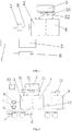
FIG.1 is a structural diagram of the rail transit braking energy recovery system provided by an embodiment of the present disclosure; -
FIG. 2 is a structural diagram of the hybrid power rail transit provided by an embodiment of the present disclosure. - In the drawings: 1: braking motor; 2: electrolytic bath; 3: hydrogen tank; 31: hydrogen pressure sensor; 32: hydrogen leakage sensor; 4: fuel battery; 5: energy storage device; 6: braking resistor; 7: rectifier module; 8: voltage regulator module; 9: control device; 10: entire vehicle air supply system; 11: entire vehicle power supply system; 12: air compressor; 13: heat dissipation system.
- In order to make the objectives, technical solutions, and advantages of the embodiments of the present disclosure clearer, the technical solutions of the embodiments of the present disclosure will be described clearly with reference to the accompanying drawings hereinafter. Obviously, the described embodiments are merely a part but not all of the embodiments of the present disclosure. On the basis of the embodiments of the present disclosure, all other embodiments obtained by the person of ordinary skill in the art without creative work shall fall within the protection scope of the present disclosure.
- As shown in
FIG.1 , a rail transit braking energy recovery system provided by the embodiments of the present disclosure includes a braking motor 1, afuel battery 4, anelectrolytic bath 2 and ahydrogen tank 3. The braking motor 1 is configured to convert braking energy of the rail transit into electric energy, and an output end of the braking motor 1 is connected to a power input end of theelectrolytic bath 2. Preferably, in the present embodiment, the output end of the braking motor 1 is connected to theelectrolytic bath 2 through arectifier module 7 and avoltage regulator module 8. Theelectrolytic bath 2 includes a hydrogen output end and an oxygen output end. The oxygen output end is configured to output oxygen produced by means of electrolysis in theelectrolytic bath 2. The hydrogen output end is connected to thehydrogen tank 3, which is connected to thefuel battery 4 and is configured to supply hydrogen to thefuel battery 4. Water in theelectrolytic bath 2 can be either water stored in the vehicle or collected water produced in other processes. The rail transit braking energy recovery system provided by the embodiments of the present disclosure is provided with theelectrolytic bath 2 that converts the braking energy recovered by the braking motor 1 into electric energy for electrolyzing water, whereby the generated hydrogen is sent to thehydrogen tank 3 and can be used as a hydrogen source of thefuel battery 4, and the generated oxygen can be introduced into the vehicle to increase the oxygen concentration in the air within the vehicle, so as to improve the air quality of the entire vehicle. When the braking energy recovery system provided by the embodiments of the present disclosure is applied to a hybrid power rail transit system, on the basis of the characteristic that the hybrid power rail transit vehicle has thehydrogen tank 3, only theelectrolytic bath 2 needs to be structurally added and the existing vehicle-mountedhydrogen tank 3 is directly used for storing hydrogen, therefore the structure is simple, the self weight of the vehicle body is reduced, the energy conversion efficiency is high, and at the same time, the injection of hydrogen is reduced and the operation cost is reduced. In addition, the purity of the hydrogen obtained by means of electrolysis is high, so that the hydrogen can be directly supplied to the fuel battery to be used without being processed. - Further, the rail transit braking energy recovery system in the present embodiment further includes a control device 9 and an
energy storage device 5 connected to the output end of the braking motor 1. The control device 9 is configured to control a current output of the braking motor 1, so that the current is output to theelectrolytic bath 2 or theenergy storage device 5. Specifically, theenergy storage device 5 in the present disclosure may be a conventional energy storage device, such as a lithium battery or a super capacitor etc. Theenergy storage device 5 can be selected according to the actual characteristics of the hybrid power rail transit, which is not limited in the embodiments of the present disclosure. The control device 9 can determine whether the electric energy output from the braking motor 1 is used for the electrolysis by theelectrolytic bath 2 or stored by theenergy storage device 5. - Further, the
hydrogen tank 3 in the present embodiment is connected with ahydrogen pressure sensor 31. Thehydrogen pressure sensor 31 is configured to control the braking motor 1 to be connected to theenergy storage device 5 when it detects that the pressure within thehydrogen tank 3 is higher than a limit value, and control the braking motor 1 to be connected to theelectrolytic bath 2 when it detects that the pressure within thehydrogen tank 3 is not higher than the limit value, so as to electrolyze and the hydrogen is collected by thehydrogen tank 3. Thehydrogen tank 3 in the present embodiment is further connected with ahydrogen leakage sensor 32. Thehydrogen leakage sensor 32 is configured to detect whether thehydrogen tank 3 is leaking. - Further, the rail transit braking energy recovery system in the present embodiment further includes a
braking resistor 6 connected to the braking motor 1. Thebraking resistor 6 directly converts the regenerated electric energy of the braking motor 1 into thermal energy during the rapid braking process, so that the regenerated electric energy is not fed back into the electric network of the power source, which will not cause voltage fluctuations of the electric network, thereby ensuring a smooth operation of the electric network of the power source. - The embodiments of the present disclosure also provide a hybrid power rail transit, as shown in
FIG.2 , including an entire vehicleair supply system 10, an entire vehiclepower supply system 11 and the rail transit braking energy recovery system above. The oxygen output end is connected to the entire vehicleair supply system 10 and thefuel battery 4 is connected to the entire vehiclepower supply system 11. The connection between the oxygen output end and the entire vehicleair supply system 10 can improve the oxygen concentration in the air of the entire vehicle and improve the air quality of the entire vehicle. Further, the hybrid power rail transit of the present embodiment further includes aheat dissipation system 13 for dissipating heat of thefuel battery 4 and theelectrolytic bath 2, so as to ensure the normal operations of thefuel battery 4 and theelectrolytic bath 2. Further, thefuel battery 4 of the present embodiment is further connected with anair compressor 12 for supplying oxygen to thefuel battery 4. - Finally, it should be noted that the embodiments above are only used to illustrate rather than to limit the technical solutions of the present disclosure; although the present disclosure has been described in detail with reference to the foregoing embodiments, those of ordinary skill in the art should understand that they can still modify the technical solutions described in the foregoing embodiments, or equivalently replace some of the technical features therein; and these modifications or replacements do not separate the essence of the corresponding technical solutions from the spirit and scope of the technical solutions of each of the embodiments of the present disclosure.
Claims (8)
- A rail transit braking energy recovery system, characterized in comprising a braking motor, a fuel battery, an electrolytic bath, and a hydrogen tank; wherein the braking motor is configured to convert braking energy of the rail transit into electric energy, and an output end of the braking motor is connected to a power input end of the electrolytic bath; the electrolytic bath comprises a hydrogen output end and an oxygen output end, the hydrogen output end being connected to the hydrogen tank and the hydrogen tank being connected to the fuel battery for supplying hydrogen to the fuel battery.
- The rail transit braking energy recovery system of claim 1, characterized in that it further comprises a control device and an energy storage device connected to the output end of the braking motor; the control device is configured to control a current output of the braking motor so that the current is output to the electrolytic bath or the energy storage device.
- The rail transit braking energy recovery system of claim 2, characterized in that the energy storage device is a lithium battery or a super capacitor.
- The rail transit braking energy recovery system of claim 2, characterized in that the hydrogen tank is connected with a hydrogen pressure sensor.
- The rail transit braking energy recovery system of claim 1, characterized in that the output end of the braking motor is connected to the electrolytic bath through a rectifier module and a voltage regulator module.
- The rail transit braking energy recovery system of any of claims 1-5, characterized in that it further comprises a braking resistor connected to the braking motor.
- A hybrid power rail transit, characterized in comprising an entire vehicle air supply system, an entire vehicle power supply system and the rail transit braking energy recovery system of any of claims 1-6; wherein the oxygen output end is connected to the entire vehicle air supply system, and the fuel battery is connected to the entire vehicle power supply system.
- The hybrid power rail transit of claim 7, characterized in that it further comprises a heat dissipation system for dissipating heat of the fuel battery and the electrolytic bath.
Applications Claiming Priority (2)
| Application Number | Priority Date | Filing Date | Title |
|---|---|---|---|
| CN201610708539.1A CN106080215B (en) | 2016-08-23 | 2016-08-23 | A rail transit braking energy recovery system and hybrid rail transit |
| PCT/CN2017/098488 WO2018036484A1 (en) | 2016-08-23 | 2017-08-22 | Rail transit braking energy recovery system and hybrid power rail transit |
Publications (3)
| Publication Number | Publication Date |
|---|---|
| EP3505385A1 true EP3505385A1 (en) | 2019-07-03 |
| EP3505385A4 EP3505385A4 (en) | 2020-04-22 |
| EP3505385B1 EP3505385B1 (en) | 2024-10-30 |
Family
ID=57225737
Family Applications (1)
| Application Number | Title | Priority Date | Filing Date |
|---|---|---|---|
| EP17842906.4A Active EP3505385B1 (en) | 2016-08-23 | 2017-08-22 | Rail transit braking energy recovery system and hybrid power rail transit |
Country Status (6)
| Country | Link |
|---|---|
| US (1) | US11052774B2 (en) |
| EP (1) | EP3505385B1 (en) |
| JP (1) | JP2019527012A (en) |
| CN (1) | CN106080215B (en) |
| ES (1) | ES2993934T3 (en) |
| WO (1) | WO2018036484A1 (en) |
Cited By (2)
| Publication number | Priority date | Publication date | Assignee | Title |
|---|---|---|---|---|
| CN112549974A (en) * | 2020-12-15 | 2021-03-26 | 武汉格罗夫氢能汽车有限公司 | Energy feedback management system and management method for hydrogen energy automobile |
| DE102023208735A1 (en) | 2023-09-08 | 2025-03-13 | Robert Bosch Gesellschaft mit beschränkter Haftung | Train with electrolysis cell unit |
Families Citing this family (11)
| Publication number | Priority date | Publication date | Assignee | Title |
|---|---|---|---|---|
| CN106080215B (en) * | 2016-08-23 | 2019-05-21 | 中车青岛四方机车车辆股份有限公司 | A rail transit braking energy recovery system and hybrid rail transit |
| CN106828117A (en) * | 2017-03-31 | 2017-06-13 | 衡阳师范学院 | Device for carrying out energy regenerating in automobile brake |
| CN108437806B (en) * | 2018-03-30 | 2019-09-13 | 中车青岛四方车辆研究所有限公司 | Configuration system and method of regenerative braking energy recovery device for urban rail transit |
| CN110341403B (en) * | 2019-07-23 | 2020-10-02 | 杜慎之 | Hydrogen energy hybrid station wagon |
| CN111384756B (en) * | 2020-03-30 | 2022-05-03 | 南京国电南自新能源科技有限公司 | Voltage-sharing control method and system for rail transit super capacitor energy storage system |
| CN112757921B (en) * | 2020-12-24 | 2022-04-15 | 北京理工大学 | Automobile-used hybrid energy storage system based on lithium battery life prediction |
| JP2022108125A (en) * | 2021-01-12 | 2022-07-25 | トヨタ自動車株式会社 | fuel cell vehicle |
| CN112937364B (en) * | 2021-04-02 | 2023-01-31 | 中车青岛四方机车车辆股份有限公司 | Vehicle braking method, system and device and traction device |
| CN113386630B (en) * | 2021-08-05 | 2022-03-08 | 吉林大学 | Intelligent network fuel cell automobile power distribution management method in low-temperature environment |
| CN114475670B (en) * | 2022-01-05 | 2023-04-25 | 中车工业研究院有限公司 | Gas fuel cell rail vehicle |
| CN114593925B (en) * | 2022-04-08 | 2024-09-10 | 中车青岛四方机车车辆股份有限公司 | A brake conversion control method, system, device, storage medium and train |
Family Cites Families (36)
| Publication number | Priority date | Publication date | Assignee | Title |
|---|---|---|---|---|
| JPS58183004U (en) * | 1982-05-28 | 1983-12-06 | トヨタ自動車株式会社 | Regenerative braking device for vehicle electric motors |
| JP2936454B2 (en) * | 1987-02-18 | 1999-08-23 | 日野自動車工業株式会社 | Charge status alarm |
| JPH06253409A (en) * | 1993-02-24 | 1994-09-09 | Aqueous Res:Kk | Hybrid power supply |
| JP3468555B2 (en) * | 1993-09-28 | 2003-11-17 | マツダ株式会社 | Vehicle fuel cell system |
| JP3232823B2 (en) * | 1993-11-16 | 2001-11-26 | 株式会社日立製作所 | Regenerative braking control method for electric vehicles |
| JPH0937412A (en) * | 1995-07-21 | 1997-02-07 | Railway Technical Res Inst | Regenerative fuel cell |
| US5900330A (en) * | 1997-09-25 | 1999-05-04 | Kagatani; Takeo | Power device |
| JP2000059918A (en) * | 1998-08-12 | 2000-02-25 | Hitachi Ltd | Automobile |
| JP2001177903A (en) * | 1999-12-22 | 2001-06-29 | Mitsubishi Electric Corp | Electric car control device |
| JP2002095167A (en) * | 2000-09-14 | 2002-03-29 | Matsushita Electric Ind Co Ltd | Surplus power storage and supply device |
| US6580977B2 (en) * | 2001-01-16 | 2003-06-17 | Ford Global Technologies, Llc | High efficiency fuel cell and battery for a hybrid powertrain |
| US6770186B2 (en) * | 2001-11-13 | 2004-08-03 | Eldat Communication Ltd. | Rechargeable hydrogen-fueled motor vehicle |
| JP4316298B2 (en) * | 2003-06-03 | 2009-08-19 | 株式会社東芝 | Electric vehicle control device |
| US20050008904A1 (en) * | 2003-07-11 | 2005-01-13 | Suppes Galen J. | Regenerative fuel cell technology |
| JP4434024B2 (en) * | 2005-01-25 | 2010-03-17 | 株式会社デンソー | HYDROGEN GENERATOR AND POWER GENERATION SYSTEM FOR GENERATING POWER GENERATED BY THE HYDROGEN GENERATOR |
| DE102006002470A1 (en) * | 2005-09-08 | 2007-03-15 | Airbus Deutschland Gmbh | Fuel cell system for supplying drinking water and oxygen has fuel cell and electrolysis cell configured so that power demand of electrolysis cell is covered by power output of fuel cell |
| US20070138006A1 (en) * | 2005-12-21 | 2007-06-21 | Oakes Thomas W | System and Method for Generating Hydrogen Gas |
| US20080121136A1 (en) * | 2006-11-28 | 2008-05-29 | General Electric Company | Hybrid locomotive and method of operating the same |
| ES2337748B1 (en) * | 2007-01-03 | 2011-02-14 | Belver Inmaculada Zamora | GENERATION AND STORAGE SYSTEM, ON BOARD, HYDROGEN AND OXYGEN FROM VEHICLE REGENERATIVE BRAKING ENERGY. |
| US20100005802A1 (en) * | 2008-07-14 | 2010-01-14 | Eric Francis | System for Producing Mechanical Energy from Electrical Energy |
| US8290653B2 (en) * | 2008-08-27 | 2012-10-16 | Ecomotors International, Inc. | Powertrain with multiple, selectable power sources |
| US8640629B2 (en) * | 2009-05-01 | 2014-02-04 | Norfolk Southern Corporation | Battery-powered all-electric and/or hybrid locomotive and related locomotive and train configurations |
| US8245801B2 (en) * | 2009-11-05 | 2012-08-21 | Bluways Usa, Inc. | Expandable energy storage control system architecture |
| CN102259595B (en) * | 2011-05-13 | 2013-07-10 | 北京工业大学 | Device and method for preparing hydrogen and oxygen on vehicle by recycling braking energy |
| CN202499021U (en) * | 2012-01-19 | 2012-10-24 | 原国平 | Petroleum-energy-substituted new energy vehicle |
| CN203318182U (en) * | 2013-05-14 | 2013-12-04 | 江西博能上饶客车有限公司 | Hybrid power city bus braking system based on super-capacitor |
| CN104283428A (en) | 2013-07-10 | 2015-01-14 | 上海工程技术大学 | Urban rail vehicle braking energy recovery converter device |
| CN203368115U (en) | 2013-07-10 | 2013-12-25 | 上海工程技术大学 | City rail vehicle braking energy absorption conversion device |
| JP6154266B2 (en) * | 2013-09-18 | 2017-06-28 | 公益財団法人鉄道総合技術研究所 | Electric vehicle, voltage conversion method, and program |
| CN103754130B (en) * | 2014-01-24 | 2016-01-20 | 电子科技大学 | For energy recovery utilizing system and the method for Liquid Hydrogen fuel battery car |
| DE102014005982A1 (en) | 2014-04-24 | 2014-11-06 | Daimler Ag | Vehicle with an electric drive machine |
| KR101601111B1 (en) * | 2014-07-01 | 2016-03-08 | 현대자동차 주식회사 | Method for calculating amount of regenerative braking for environmentally-friently vehicle |
| KR20160015070A (en) * | 2014-07-30 | 2016-02-12 | 현대자동차주식회사 | System for fuel cell vehicle |
| CN205202763U (en) * | 2015-11-30 | 2016-05-04 | 北汽福田汽车股份有限公司 | Electric automobile and power supply system thereof |
| CN106080215B (en) | 2016-08-23 | 2019-05-21 | 中车青岛四方机车车辆股份有限公司 | A rail transit braking energy recovery system and hybrid rail transit |
| CN205970877U (en) * | 2016-08-23 | 2017-02-22 | 中车青岛四方机车车辆股份有限公司 | Track traffic braking can recycle system and hybrid track traffic |
-
2016
- 2016-08-23 CN CN201610708539.1A patent/CN106080215B/en active Active
-
2017
- 2017-08-22 WO PCT/CN2017/098488 patent/WO2018036484A1/en not_active Ceased
- 2017-08-22 ES ES17842906T patent/ES2993934T3/en active Active
- 2017-08-22 EP EP17842906.4A patent/EP3505385B1/en active Active
- 2017-08-22 JP JP2019507818A patent/JP2019527012A/en active Pending
- 2017-08-22 US US16/327,805 patent/US11052774B2/en active Active
Cited By (2)
| Publication number | Priority date | Publication date | Assignee | Title |
|---|---|---|---|---|
| CN112549974A (en) * | 2020-12-15 | 2021-03-26 | 武汉格罗夫氢能汽车有限公司 | Energy feedback management system and management method for hydrogen energy automobile |
| DE102023208735A1 (en) | 2023-09-08 | 2025-03-13 | Robert Bosch Gesellschaft mit beschränkter Haftung | Train with electrolysis cell unit |
Also Published As
| Publication number | Publication date |
|---|---|
| WO2018036484A1 (en) | 2018-03-01 |
| EP3505385A4 (en) | 2020-04-22 |
| ES2993934T3 (en) | 2025-01-14 |
| US11052774B2 (en) | 2021-07-06 |
| CN106080215A (en) | 2016-11-09 |
| CN106080215B (en) | 2019-05-21 |
| US20190225089A1 (en) | 2019-07-25 |
| JP2019527012A (en) | 2019-09-19 |
| EP3505385B1 (en) | 2024-10-30 |
Similar Documents
| Publication | Publication Date | Title |
|---|---|---|
| US11052774B2 (en) | Rail transit braking energy recovery system and hybrid power rail transit | |
| CN104044483B (en) | A kind of electrical vehicular power power supply without outer charging | |
| CN204156591U (en) | Elevator emergency energy saver | |
| CN108692185B (en) | Hydrogen production and hydrogenation integrated machine for high-pressure high-purity hydrogen | |
| CN110571857A (en) | Energy management coordination system based on photovoltaic and fuel cell combined power generation system | |
| WO2017076333A1 (en) | Hydrogen fueled power system, and hydrogen fueled power tramcar | |
| CN112109578A (en) | Vehicle energy supply station and control method thereof | |
| KR20190049021A (en) | Renewable energy storage system and operating method thereof | |
| CN112060978B (en) | A fuel cell vehicle energy storage management system and method | |
| CN102114789A (en) | Multifunctional fuel-cell-driven automotive system | |
| CN112751376A (en) | Energy management method of hybrid power supply system | |
| CN104627002A (en) | Fuel battery and solar energy combined supply type electric vehicle | |
| CN111555256A (en) | Direct-current micro-grid system and control method | |
| CN113428335B (en) | An improved marine fuel cell pusher-barge hybrid power system and its control method | |
| US9637091B2 (en) | Heterogeneous energy supply system | |
| CN113949054A (en) | Power grid autonomous system and method | |
| CN107612029A (en) | a power supply system | |
| Lianfu et al. | Research on the integrated braking energy recovery strategy based on super-capacitor energy storage | |
| CN206141344U (en) | Quick charging system of family electric automobile | |
| CN205846823U (en) | A hydrogen fuel cell vehicle service station using regenerative braking energy of trains | |
| CN205970877U (en) | Track traffic braking can recycle system and hybrid track traffic | |
| CN217789379U (en) | Electrolysis device | |
| CN218124382U (en) | Mobile hydrogen fuel generator set | |
| CN215552583U (en) | Power system based on proton exchange membrane fuel cell | |
| CN212343324U (en) | Direct-current micro-grid system with double voltage levels and double-grid architecture |
Legal Events
| Date | Code | Title | Description |
|---|---|---|---|
| STAA | Information on the status of an ep patent application or granted ep patent |
Free format text: STATUS: THE INTERNATIONAL PUBLICATION HAS BEEN MADE |
|
| PUAI | Public reference made under article 153(3) epc to a published international application that has entered the european phase |
Free format text: ORIGINAL CODE: 0009012 |
|
| STAA | Information on the status of an ep patent application or granted ep patent |
Free format text: STATUS: REQUEST FOR EXAMINATION WAS MADE |
|
| 17P | Request for examination filed |
Effective date: 20190319 |
|
| AK | Designated contracting states |
Kind code of ref document: A1 Designated state(s): AL AT BE BG CH CY CZ DE DK EE ES FI FR GB GR HR HU IE IS IT LI LT LU LV MC MK MT NL NO PL PT RO RS SE SI SK SM TR |
|
| AX | Request for extension of the european patent |
Extension state: BA ME |
|
| DAV | Request for validation of the european patent (deleted) | ||
| DAX | Request for extension of the european patent (deleted) | ||
| REG | Reference to a national code |
Ref country code: DE Ref legal event code: R079 Ref document number: 602017085815 Country of ref document: DE Free format text: PREVIOUS MAIN CLASS: B60L0007220000 Ipc: B60L0007100000 |
|
| A4 | Supplementary search report drawn up and despatched |
Effective date: 20200323 |
|
| RIC1 | Information provided on ipc code assigned before grant |
Ipc: B60L 50/70 20190101ALI20200317BHEP Ipc: B60L 7/10 20060101AFI20200317BHEP |
|
| STAA | Information on the status of an ep patent application or granted ep patent |
Free format text: STATUS: EXAMINATION IS IN PROGRESS |
|
| 17Q | First examination report despatched |
Effective date: 20210618 |
|
| GRAP | Despatch of communication of intention to grant a patent |
Free format text: ORIGINAL CODE: EPIDOSNIGR1 |
|
| STAA | Information on the status of an ep patent application or granted ep patent |
Free format text: STATUS: GRANT OF PATENT IS INTENDED |
|
| INTG | Intention to grant announced |
Effective date: 20240621 |
|
| GRAS | Grant fee paid |
Free format text: ORIGINAL CODE: EPIDOSNIGR3 |
|
| GRAA | (expected) grant |
Free format text: ORIGINAL CODE: 0009210 |
|
| STAA | Information on the status of an ep patent application or granted ep patent |
Free format text: STATUS: THE PATENT HAS BEEN GRANTED |
|
| AK | Designated contracting states |
Kind code of ref document: B1 Designated state(s): AL AT BE BG CH CY CZ DE DK EE ES FI FR GB GR HR HU IE IS IT LI LT LU LV MC MK MT NL NO PL PT RO RS SE SI SK SM TR |
|
| REG | Reference to a national code |
Ref country code: GB Ref legal event code: FG4D |
|
| REG | Reference to a national code |
Ref country code: CH Ref legal event code: EP |
|
| REG | Reference to a national code |
Ref country code: IE Ref legal event code: FG4D |
|
| REG | Reference to a national code |
Ref country code: DE Ref legal event code: R096 Ref document number: 602017085815 Country of ref document: DE |
|
| REG | Reference to a national code |
Ref country code: ES Ref legal event code: FG2A Ref document number: 2993934 Country of ref document: ES Kind code of ref document: T3 Effective date: 20250114 |
|
| REG | Reference to a national code |
Ref country code: LT Ref legal event code: MG9D |
|
| REG | Reference to a national code |
Ref country code: NL Ref legal event code: MP Effective date: 20241030 |
|
| PG25 | Lapsed in a contracting state [announced via postgrant information from national office to epo] |
Ref country code: PT Free format text: LAPSE BECAUSE OF FAILURE TO SUBMIT A TRANSLATION OF THE DESCRIPTION OR TO PAY THE FEE WITHIN THE PRESCRIBED TIME-LIMIT Effective date: 20250228 Ref country code: IS Free format text: LAPSE BECAUSE OF FAILURE TO SUBMIT A TRANSLATION OF THE DESCRIPTION OR TO PAY THE FEE WITHIN THE PRESCRIBED TIME-LIMIT Effective date: 20250228 Ref country code: HR Free format text: LAPSE BECAUSE OF FAILURE TO SUBMIT A TRANSLATION OF THE DESCRIPTION OR TO PAY THE FEE WITHIN THE PRESCRIBED TIME-LIMIT Effective date: 20241030 |
|
| PG25 | Lapsed in a contracting state [announced via postgrant information from national office to epo] |
Ref country code: FI Free format text: LAPSE BECAUSE OF FAILURE TO SUBMIT A TRANSLATION OF THE DESCRIPTION OR TO PAY THE FEE WITHIN THE PRESCRIBED TIME-LIMIT Effective date: 20241030 Ref country code: NL Free format text: LAPSE BECAUSE OF FAILURE TO SUBMIT A TRANSLATION OF THE DESCRIPTION OR TO PAY THE FEE WITHIN THE PRESCRIBED TIME-LIMIT Effective date: 20241030 |
|
| REG | Reference to a national code |
Ref country code: AT Ref legal event code: MK05 Ref document number: 1736585 Country of ref document: AT Kind code of ref document: T Effective date: 20241030 |
|
| PG25 | Lapsed in a contracting state [announced via postgrant information from national office to epo] |
Ref country code: BG Free format text: LAPSE BECAUSE OF FAILURE TO SUBMIT A TRANSLATION OF THE DESCRIPTION OR TO PAY THE FEE WITHIN THE PRESCRIBED TIME-LIMIT Effective date: 20241030 |
|
| PG25 | Lapsed in a contracting state [announced via postgrant information from national office to epo] |
Ref country code: NO Free format text: LAPSE BECAUSE OF FAILURE TO SUBMIT A TRANSLATION OF THE DESCRIPTION OR TO PAY THE FEE WITHIN THE PRESCRIBED TIME-LIMIT Effective date: 20250130 |
|
| PG25 | Lapsed in a contracting state [announced via postgrant information from national office to epo] |
Ref country code: LV Free format text: LAPSE BECAUSE OF FAILURE TO SUBMIT A TRANSLATION OF THE DESCRIPTION OR TO PAY THE FEE WITHIN THE PRESCRIBED TIME-LIMIT Effective date: 20241030 Ref country code: GR Free format text: LAPSE BECAUSE OF FAILURE TO SUBMIT A TRANSLATION OF THE DESCRIPTION OR TO PAY THE FEE WITHIN THE PRESCRIBED TIME-LIMIT Effective date: 20250131 Ref country code: AT Free format text: LAPSE BECAUSE OF FAILURE TO SUBMIT A TRANSLATION OF THE DESCRIPTION OR TO PAY THE FEE WITHIN THE PRESCRIBED TIME-LIMIT Effective date: 20241030 |
|
| PG25 | Lapsed in a contracting state [announced via postgrant information from national office to epo] |
Ref country code: PL Free format text: LAPSE BECAUSE OF FAILURE TO SUBMIT A TRANSLATION OF THE DESCRIPTION OR TO PAY THE FEE WITHIN THE PRESCRIBED TIME-LIMIT Effective date: 20241030 |
|
| PG25 | Lapsed in a contracting state [announced via postgrant information from national office to epo] |
Ref country code: RS Free format text: LAPSE BECAUSE OF FAILURE TO SUBMIT A TRANSLATION OF THE DESCRIPTION OR TO PAY THE FEE WITHIN THE PRESCRIBED TIME-LIMIT Effective date: 20250130 |
|
| PG25 | Lapsed in a contracting state [announced via postgrant information from national office to epo] |
Ref country code: SM Free format text: LAPSE BECAUSE OF FAILURE TO SUBMIT A TRANSLATION OF THE DESCRIPTION OR TO PAY THE FEE WITHIN THE PRESCRIBED TIME-LIMIT Effective date: 20241030 |
|
| PG25 | Lapsed in a contracting state [announced via postgrant information from national office to epo] |
Ref country code: DK Free format text: LAPSE BECAUSE OF FAILURE TO SUBMIT A TRANSLATION OF THE DESCRIPTION OR TO PAY THE FEE WITHIN THE PRESCRIBED TIME-LIMIT Effective date: 20241030 |
|
| PG25 | Lapsed in a contracting state [announced via postgrant information from national office to epo] |
Ref country code: EE Free format text: LAPSE BECAUSE OF FAILURE TO SUBMIT A TRANSLATION OF THE DESCRIPTION OR TO PAY THE FEE WITHIN THE PRESCRIBED TIME-LIMIT Effective date: 20241030 |
|
| PGFP | Annual fee paid to national office [announced via postgrant information from national office to epo] |
Ref country code: FR Payment date: 20250603 Year of fee payment: 9 |
|
| PG25 | Lapsed in a contracting state [announced via postgrant information from national office to epo] |
Ref country code: RO Free format text: LAPSE BECAUSE OF FAILURE TO SUBMIT A TRANSLATION OF THE DESCRIPTION OR TO PAY THE FEE WITHIN THE PRESCRIBED TIME-LIMIT Effective date: 20241030 |
|
| PG25 | Lapsed in a contracting state [announced via postgrant information from national office to epo] |
Ref country code: SK Free format text: LAPSE BECAUSE OF FAILURE TO SUBMIT A TRANSLATION OF THE DESCRIPTION OR TO PAY THE FEE WITHIN THE PRESCRIBED TIME-LIMIT Effective date: 20241030 |
|
| PG25 | Lapsed in a contracting state [announced via postgrant information from national office to epo] |
Ref country code: CZ Free format text: LAPSE BECAUSE OF FAILURE TO SUBMIT A TRANSLATION OF THE DESCRIPTION OR TO PAY THE FEE WITHIN THE PRESCRIBED TIME-LIMIT Effective date: 20241030 |
|
| PG25 | Lapsed in a contracting state [announced via postgrant information from national office to epo] |
Ref country code: IT Free format text: LAPSE BECAUSE OF FAILURE TO SUBMIT A TRANSLATION OF THE DESCRIPTION OR TO PAY THE FEE WITHIN THE PRESCRIBED TIME-LIMIT Effective date: 20241030 |
|
| REG | Reference to a national code |
Ref country code: DE Ref legal event code: R097 Ref document number: 602017085815 Country of ref document: DE |
|
| PLBE | No opposition filed within time limit |
Free format text: ORIGINAL CODE: 0009261 |
|
| STAA | Information on the status of an ep patent application or granted ep patent |
Free format text: STATUS: NO OPPOSITION FILED WITHIN TIME LIMIT |
|
| PG25 | Lapsed in a contracting state [announced via postgrant information from national office to epo] |
Ref country code: SE Free format text: LAPSE BECAUSE OF FAILURE TO SUBMIT A TRANSLATION OF THE DESCRIPTION OR TO PAY THE FEE WITHIN THE PRESCRIBED TIME-LIMIT Effective date: 20241030 |
|
| 26N | No opposition filed |
Effective date: 20250731 |
|
| PGFP | Annual fee paid to national office [announced via postgrant information from national office to epo] |
Ref country code: ES Payment date: 20250917 Year of fee payment: 9 |
|
| PGFP | Annual fee paid to national office [announced via postgrant information from national office to epo] |
Ref country code: DE Payment date: 20250819 Year of fee payment: 9 |
|
| REG | Reference to a national code |
Ref country code: CH Ref legal event code: H13 Free format text: ST27 STATUS EVENT CODE: U-0-0-H10-H13 (AS PROVIDED BY THE NATIONAL OFFICE) Effective date: 20260324 |
|
| PG25 | Lapsed in a contracting state [announced via postgrant information from national office to epo] |
Ref country code: MC Free format text: LAPSE BECAUSE OF FAILURE TO SUBMIT A TRANSLATION OF THE DESCRIPTION OR TO PAY THE FEE WITHIN THE PRESCRIBED TIME-LIMIT Effective date: 20241030 |
|
| PG25 | Lapsed in a contracting state [announced via postgrant information from national office to epo] |
Ref country code: LU Free format text: LAPSE BECAUSE OF NON-PAYMENT OF DUE FEES Effective date: 20250822 |
|
| PG25 | Lapsed in a contracting state [announced via postgrant information from national office to epo] |
Ref country code: CH Free format text: LAPSE BECAUSE OF NON-PAYMENT OF DUE FEES Effective date: 20250831 |
|
| GBPC | Gb: european patent ceased through non-payment of renewal fee |
Effective date: 20250822 |