EP3505350A1 - Liquid ejecting head and liquid ejecting apparatus - Google Patents
Liquid ejecting head and liquid ejecting apparatus Download PDFInfo
- Publication number
- EP3505350A1 EP3505350A1 EP18248129.1A EP18248129A EP3505350A1 EP 3505350 A1 EP3505350 A1 EP 3505350A1 EP 18248129 A EP18248129 A EP 18248129A EP 3505350 A1 EP3505350 A1 EP 3505350A1
- Authority
- EP
- European Patent Office
- Prior art keywords
- space
- liquid ejecting
- case member
- moisture
- ejecting head
- Prior art date
- Legal status (The legal status is an assumption and is not a legal conclusion. Google has not performed a legal analysis and makes no representation as to the accuracy of the status listed.)
- Withdrawn
Links
- 239000007788 liquid Substances 0.000 title claims abstract description 111
- 238000004891 communication Methods 0.000 claims abstract description 66
- 238000007789 sealing Methods 0.000 claims abstract description 27
- 239000006096 absorbing agent Substances 0.000 claims description 33
- 239000000758 substrate Substances 0.000 claims description 25
- 230000002745 absorbent Effects 0.000 abstract description 25
- 239000002250 absorbent Substances 0.000 abstract description 25
- 238000009833 condensation Methods 0.000 description 30
- 230000005494 condensation Effects 0.000 description 30
- XLYOFNOQVPJJNP-UHFFFAOYSA-N water Substances O XLYOFNOQVPJJNP-UHFFFAOYSA-N 0.000 description 16
- 230000004308 accommodation Effects 0.000 description 14
- 239000000853 adhesive Substances 0.000 description 9
- 230000001070 adhesive effect Effects 0.000 description 9
- 239000000463 material Substances 0.000 description 8
- 230000004048 modification Effects 0.000 description 6
- 238000012986 modification Methods 0.000 description 6
- VYPSYNLAJGMNEJ-UHFFFAOYSA-N Silicium dioxide Chemical compound O=[Si]=O VYPSYNLAJGMNEJ-UHFFFAOYSA-N 0.000 description 5
- 230000000694 effects Effects 0.000 description 5
- 239000000741 silica gel Substances 0.000 description 5
- 229910002027 silica gel Inorganic materials 0.000 description 5
- ZAMOUSCENKQFHK-UHFFFAOYSA-N Chlorine atom Chemical compound [Cl] ZAMOUSCENKQFHK-UHFFFAOYSA-N 0.000 description 4
- NINIDFKCEFEMDL-UHFFFAOYSA-N Sulfur Chemical compound [S] NINIDFKCEFEMDL-UHFFFAOYSA-N 0.000 description 4
- 238000010521 absorption reaction Methods 0.000 description 4
- 239000000460 chlorine Substances 0.000 description 4
- 229910052801 chlorine Inorganic materials 0.000 description 4
- 230000008020 evaporation Effects 0.000 description 4
- 238000001704 evaporation Methods 0.000 description 4
- 238000007639 printing Methods 0.000 description 4
- 239000011593 sulfur Substances 0.000 description 4
- 229910052717 sulfur Inorganic materials 0.000 description 4
- 238000004519 manufacturing process Methods 0.000 description 3
- 239000000243 solution Substances 0.000 description 3
- 239000011247 coating layer Substances 0.000 description 2
- 238000005336 cracking Methods 0.000 description 2
- 230000006866 deterioration Effects 0.000 description 2
- 238000005401 electroluminescence Methods 0.000 description 2
- 230000007062 hydrolysis Effects 0.000 description 2
- 238000006460 hydrolysis reaction Methods 0.000 description 2
- 230000000644 propagated effect Effects 0.000 description 2
- 239000011347 resin Substances 0.000 description 2
- 229920005989 resin Polymers 0.000 description 2
- 230000032258 transport Effects 0.000 description 2
- 230000007723 transport mechanism Effects 0.000 description 2
- 239000011358 absorbing material Substances 0.000 description 1
- 230000008901 benefit Effects 0.000 description 1
- 239000011248 coating agent Substances 0.000 description 1
- 238000000576 coating method Methods 0.000 description 1
- 238000004040 coloring Methods 0.000 description 1
- 239000004020 conductor Substances 0.000 description 1
- 125000001153 fluoro group Chemical group F* 0.000 description 1
- 230000020169 heat generation Effects 0.000 description 1
- 238000010438 heat treatment Methods 0.000 description 1
- 238000001746 injection moulding Methods 0.000 description 1
- 239000004973 liquid crystal related substance Substances 0.000 description 1
- 238000000034 method Methods 0.000 description 1
- 229920006395 saturated elastomer Polymers 0.000 description 1
- 229910052710 silicon Inorganic materials 0.000 description 1
- 239000010703 silicon Substances 0.000 description 1
Images




Classifications
-
- B—PERFORMING OPERATIONS; TRANSPORTING
- B41—PRINTING; LINING MACHINES; TYPEWRITERS; STAMPS
- B41J—TYPEWRITERS; SELECTIVE PRINTING MECHANISMS, i.e. MECHANISMS PRINTING OTHERWISE THAN FROM A FORME; CORRECTION OF TYPOGRAPHICAL ERRORS
- B41J2/00—Typewriters or selective printing mechanisms characterised by the printing or marking process for which they are designed
- B41J2/005—Typewriters or selective printing mechanisms characterised by the printing or marking process for which they are designed characterised by bringing liquid or particles selectively into contact with a printing material
- B41J2/01—Ink jet
- B41J2/135—Nozzles
- B41J2/14—Structure thereof only for on-demand ink jet heads
- B41J2/14201—Structure of print heads with piezoelectric elements
- B41J2/14233—Structure of print heads with piezoelectric elements of film type, deformed by bending and disposed on a diaphragm
-
- B—PERFORMING OPERATIONS; TRANSPORTING
- B41—PRINTING; LINING MACHINES; TYPEWRITERS; STAMPS
- B41J—TYPEWRITERS; SELECTIVE PRINTING MECHANISMS, i.e. MECHANISMS PRINTING OTHERWISE THAN FROM A FORME; CORRECTION OF TYPOGRAPHICAL ERRORS
- B41J2/00—Typewriters or selective printing mechanisms characterised by the printing or marking process for which they are designed
- B41J2/005—Typewriters or selective printing mechanisms characterised by the printing or marking process for which they are designed characterised by bringing liquid or particles selectively into contact with a printing material
- B41J2/01—Ink jet
- B41J2/015—Ink jet characterised by the jet generation process
- B41J2/04—Ink jet characterised by the jet generation process generating single droplets or particles on demand
- B41J2/045—Ink jet characterised by the jet generation process generating single droplets or particles on demand by pressure, e.g. electromechanical transducers
- B41J2/04501—Control methods or devices therefor, e.g. driver circuits, control circuits
- B41J2/04581—Control methods or devices therefor, e.g. driver circuits, control circuits controlling heads based on piezoelectric elements
-
- B—PERFORMING OPERATIONS; TRANSPORTING
- B41—PRINTING; LINING MACHINES; TYPEWRITERS; STAMPS
- B41J—TYPEWRITERS; SELECTIVE PRINTING MECHANISMS, i.e. MECHANISMS PRINTING OTHERWISE THAN FROM A FORME; CORRECTION OF TYPOGRAPHICAL ERRORS
- B41J2/00—Typewriters or selective printing mechanisms characterised by the printing or marking process for which they are designed
- B41J2/005—Typewriters or selective printing mechanisms characterised by the printing or marking process for which they are designed characterised by bringing liquid or particles selectively into contact with a printing material
- B41J2/01—Ink jet
- B41J2/135—Nozzles
- B41J2/14—Structure thereof only for on-demand ink jet heads
-
- B—PERFORMING OPERATIONS; TRANSPORTING
- B41—PRINTING; LINING MACHINES; TYPEWRITERS; STAMPS
- B41J—TYPEWRITERS; SELECTIVE PRINTING MECHANISMS, i.e. MECHANISMS PRINTING OTHERWISE THAN FROM A FORME; CORRECTION OF TYPOGRAPHICAL ERRORS
- B41J2/00—Typewriters or selective printing mechanisms characterised by the printing or marking process for which they are designed
- B41J2/005—Typewriters or selective printing mechanisms characterised by the printing or marking process for which they are designed characterised by bringing liquid or particles selectively into contact with a printing material
- B41J2/01—Ink jet
- B41J2/135—Nozzles
- B41J2/14—Structure thereof only for on-demand ink jet heads
- B41J2/14201—Structure of print heads with piezoelectric elements
-
- B—PERFORMING OPERATIONS; TRANSPORTING
- B41—PRINTING; LINING MACHINES; TYPEWRITERS; STAMPS
- B41J—TYPEWRITERS; SELECTIVE PRINTING MECHANISMS, i.e. MECHANISMS PRINTING OTHERWISE THAN FROM A FORME; CORRECTION OF TYPOGRAPHICAL ERRORS
- B41J29/00—Details of, or accessories for, typewriters or selective printing mechanisms not otherwise provided for
- B41J29/02—Framework
-
- B—PERFORMING OPERATIONS; TRANSPORTING
- B41—PRINTING; LINING MACHINES; TYPEWRITERS; STAMPS
- B41J—TYPEWRITERS; SELECTIVE PRINTING MECHANISMS, i.e. MECHANISMS PRINTING OTHERWISE THAN FROM A FORME; CORRECTION OF TYPOGRAPHICAL ERRORS
- B41J29/00—Details of, or accessories for, typewriters or selective printing mechanisms not otherwise provided for
- B41J29/377—Cooling or ventilating arrangements
-
- H—ELECTRICITY
- H10—SEMICONDUCTOR DEVICES; ELECTRIC SOLID-STATE DEVICES NOT OTHERWISE PROVIDED FOR
- H10N—ELECTRIC SOLID-STATE DEVICES NOT OTHERWISE PROVIDED FOR
- H10N30/00—Piezoelectric or electrostrictive devices
- H10N30/80—Constructional details
- H10N30/88—Mounts; Supports; Enclosures; Casings
- H10N30/883—Additional insulation means preventing electrical, physical or chemical damage, e.g. protective coatings
-
- B—PERFORMING OPERATIONS; TRANSPORTING
- B41—PRINTING; LINING MACHINES; TYPEWRITERS; STAMPS
- B41J—TYPEWRITERS; SELECTIVE PRINTING MECHANISMS, i.e. MECHANISMS PRINTING OTHERWISE THAN FROM A FORME; CORRECTION OF TYPOGRAPHICAL ERRORS
- B41J2/00—Typewriters or selective printing mechanisms characterised by the printing or marking process for which they are designed
- B41J2/005—Typewriters or selective printing mechanisms characterised by the printing or marking process for which they are designed characterised by bringing liquid or particles selectively into contact with a printing material
- B41J2/01—Ink jet
- B41J2/135—Nozzles
- B41J2/14—Structure thereof only for on-demand ink jet heads
- B41J2/14201—Structure of print heads with piezoelectric elements
- B41J2/14233—Structure of print heads with piezoelectric elements of film type, deformed by bending and disposed on a diaphragm
- B41J2002/14241—Structure of print heads with piezoelectric elements of film type, deformed by bending and disposed on a diaphragm having a cover around the piezoelectric thin film element
-
- H—ELECTRICITY
- H10—SEMICONDUCTOR DEVICES; ELECTRIC SOLID-STATE DEVICES NOT OTHERWISE PROVIDED FOR
- H10N—ELECTRIC SOLID-STATE DEVICES NOT OTHERWISE PROVIDED FOR
- H10N30/00—Piezoelectric or electrostrictive devices
- H10N30/20—Piezoelectric or electrostrictive devices with electrical input and mechanical output, e.g. functioning as actuators or vibrators
- H10N30/204—Piezoelectric or electrostrictive devices with electrical input and mechanical output, e.g. functioning as actuators or vibrators using bending displacement, e.g. unimorph, bimorph or multimorph cantilever or membrane benders
- H10N30/2047—Membrane type
Definitions
- the present invention relates to a technique for ejecting a liquid such as ink.
- a space in which the driving element is accommodated is sealed to protect the driving element from moisture.
- a space in which the driving element is accommodated is sealed by bonding a sealing plate with an adhesive to a substrate on which the accommodation space of the driving element is formed. The adhesive that protrudes during such a bonding is accommodated in an adhesive escape space portion.
- the accommodation space of the driving element becomes a sealed space, so that a vibration of the pressure chamber caused by driving of the driving element is propagated to the accommodation space of the driving element, and a pressure fluctuation occurs in the accommodation space of the driving element as well.
- each pressure chamber is also affected by the pressure fluctuation of the accommodation space of the driving element, there is a concern that an ejection characteristic changes due to the pressure fluctuation of the accommodation space of the driving element.
- the pressure fluctuation of the accommodation space of the driving element also changes depending on the number of the driving elements to be driven, so that a difference is generated in the pressure fluctuation gap. Therefore, there is a concern that the ejection characteristic changes depending on the number of the driving elements to be driven.
- An advantage of some aspects of the invention is that the driving element is protected from moisture while the pressure fluctuation in the space that accommodates the driving element is suppressed.
- a liquid ejecting head that includes a driving element that causes a liquid to be ejected from a nozzle by fluctuating a pressure of a pressure chamber filled with the liquid, a sealing body that forms a first space for accommodating the driving element, a case member that forms a second space for surrounding the sealing body, an atmosphere vent that is formed in the case member and through which the second space communicates with atmosphere, a communication hole that is formed in the sealing body and through which the first space communicates with the second space, and a moisture absorbent in the second space.
- the fluctuation of the pressure in the accommodation space caused by the vibration of the pressure chamber can be suppressed.
- the moisture absorbent is disposed in the second space, even if the moisture enters the second space from the atmosphere vent, the moisture is absorbed by the moisture absorbent in the second space. Therefore, since the moisture entering the first space through the communication hole can be reduced, the driving element can be protected from moisture. With this configuration, the driving element can be protected from the moisture while the pressure fluctuation of the space for accommodating the driving element is suppressed.
- the moisture absorbent may be in a position closer to the communication hole than to the atmosphere vent.
- the moisture absorbent since the moisture absorbent is in a position closer to the communication hole than to the atmosphere vent, compared with a case where the moisture absorbent is in a position close to the atmosphere vent, it is possible to suppress suction of the moisture outside the second space from the atmosphere vent and absorption of that moisture. Therefore, the time during which hygroscopic capacity of the moisture absorbent can be maintained can be extended. Further, since the moisture absorbent is in a position close to the communication hole, compared with a case where the moisture absorbent is in a position away from the communication hole, it is possible to make it difficult for the moisture to enter from the communication hole.
- the atmosphere vent may be in a position higher than the communication hole in a vertical direction, and the moisture absorbent may be disposed between the atmosphere vent and the communication hole in the vertical direction.
- the water component of the moisture that entered the second space from the atmosphere vent can condense between the atmosphere vent and the communication hole due to a temperature drop and a dew condensation droplet may adhere to an inner circumferential surface of the case member.
- the dew condensation droplet evaporates and the moisture increases when a temperature rises again thereafter.
- the moisture absorbent disposed between the atmosphere vent and the communication hole can absorb the moisture efficiently. Therefore, even when the dew condensation droplet evaporates on the inner circumferential surface of the case member, entry of the moisture into the communication hole can be suppressed.
- the second space may include a recess portion that has a bottom surface positioned lower than the communication hole in the vertical direction.
- the case member may have a higher thermal conductivity than the sealing body.
- the case member since the case member has a higher thermal conductivity than the sealing body, when a temperature falls, the water component of the moisture that entered the second space can be condensed actively on the inner circumferential surface of the case member in the second space. Therefore, since the moisture of the first space can be lowered, the dew condensation can be made difficult in the first space. Further, when a temperature rises, the dew condensation droplet condensed on the inner circumferential surface of case member evaporates again in the second space, so that the moisture is absorbed by the moisture absorbent easily.
- the case member may include at least a lower case member on a lower side in the vertical direction and an upper case member on an upper side higher than the lower case member in the vertical direction, the moisture absorbent may be disposed in the upper case member, and the lower case member may have a higher thermal conductivity than the upper case member.
- a minimum opening area of the communication hole may be smaller than a minimum opening area of the atmosphere vent.
- a volume of the first space may be smaller than a volume of the second space.
- the dew condensation volume in the first space can be made smaller than the dew condensation volume in the second space. Therefore, the characteristic deterioration of the driving element caused by the dew condensation can be reduced.
- the volume of the second space is larger than the volume of the first space, the moisture absorbent disposed in the second space is increased easily, and thus, the hygroscopic effect by the moisture absorbent can be enhanced.
- a circuit substrate may be disposed in the second space.
- the temperature of the second space rises more easily than the temperature of the first space, and thus, the permissible volume of the saturation water vapor in the second space increases, and thus, the evaporation volume of the water component increases easily.
- the moisture absorbent is present in the second space in which the circuit substrate, the ambient temperature of which rises easily, is disposed, the moisture of the second space in which the evaporation volume of the water component increases easily can be absorbed efficiently.
- a plurality of sealing bodies may be provided, the communication holes may be provided corresponding to each sealing body, and the first space of each of the sealing bodies may communicate with the second space with each other through each of the communication holes.
- a liquid ejecting apparatus that includes the liquid ejecting head described above.
- the liquid ejecting apparatus that includes the liquid ejecting head that can protect the driving element from the moisture while suppressing the pressure fluctuation of the space that accommodates the driving element can be provided.
- Fig. 1 shows a first embodiment of the invention, in which a partial configuration of the liquid ejecting apparatus 10 is illustrated.
- the liquid ejecting apparatus 10 of the first embodiment is an ink jet type printing apparatus that ejects ink, an example of a liquid, onto a medium 11 such as printing paper and the like.
- the liquid ejecting apparatus 10 shown in Fig. 1 includes a control device 12, a transport mechanism 15, a carriage 18, and a liquid ejecting head 20.
- a liquid container 14 that stores ink is mounted on the liquid ejecting apparatus 10.
- the liquid container 14 is an ink tank type cartridge made of a box-shaped container attachable to and detachable from the main body of the liquid ejecting apparatus 10.
- the liquid container 14 is not limited to a box-shaped container and may for example be an ink pack type cartridge made of a sack-shaped container.
- ink is stored in the liquid container 14.
- the ink may be black ink or may be color ink.
- the ink stored in the liquid container 14 is pressure-fed to the liquid ejecting head 20.
- the control device 12 comprehensively controls each element of the liquid ejecting apparatus 10.
- the transport mechanism 15 transports the medium 11 in the Y-direction under the control of the control device 12.
- the liquid ejecting head 20 ejects ink supplied from the liquid container 14 onto the medium 11 from each of a plurality of the nozzles N under the control of the control device 12.
- the liquid ejecting head 20 is mounted on the carriage 18.
- a case where one liquid ejecting head 20 is mounted on the carriage 18 is presented as an example, but the invention is not limited thereto.
- a plurality of the liquid ejecting heads 20 may be mounted on the carriage 18.
- the control device 12 causes the carriage 18 to reciprocate in the X-direction which intersects with Y-direction (orthogonal in Fig. 1 ).
- a desired image is formed on the surface of the medium 11 by ejecting ink from the liquid ejecting head 20 onto the medium 11 in concurrence with a repetition of the transport of the medium 11 and the reciprocation of the carriage 18.
- a plurality of the liquid ejecting heads 20 may be mounted on the carriage 18.
- a liquid ejection section 70 is mounted in the liquid ejecting head 20, a liquid ejection section 70 is mounted.
- a nozzle row is disposed in the liquid ejection section 70.
- the nozzle row is a collection of a plurality of nozzles N arranged in a straight line in the Y-direction.
- the ink supplied from the liquid container 14 is ejected from each nozzle N.
- the nozzle N of each nozzle row is formed on an ejection surface 22 (the surface facing the medium 11) of the liquid ejecting head 20.
- the number and arrangement of the liquid ejection section 70 and the nozzle row are not limited to the example.
- a plurality of nozzle rows in a zigzag or staggered pattern on the ejection surface 22 of the liquid ejecting head 20.
- the direction perpendicular to the X-Y plane (a plane parallel to the surface of medium 11) is denoted as the Z-direction.
- Fig. 2 shows a sectional view of the liquid ejecting head 20 shown in Fig. 1 taken along the line II-II.
- the liquid ejecting head 20 includes the liquid ejection section 70 and the case member 30.
- the liquid ejection section 70 is accommodated in the case member 30.
- an opening section 31 is formed on the positive side (downward in Fig. 2 ) of the Z-direction of the case member 30.
- the liquid ejection section 70 is fixed to the case member 30 so that the ejection surface 22 is exposed from the opening section 31.
- the liquid ejection section 70 includes ejection sections 702 corresponding to each nozzle N.
- Fig. 3 shows a sectional view of the liquid ejection section 70 with a focus on one random ejection section 702.
- the liquid ejection section 70 shown in Fig. 3 is a structure in which the pressure chamber substrate 72, the diaphragm 73, the piezoelectric element 74, and the support body 75 are disposed on one side of the flow path substrate 71 while the nozzle plate 76 is disposed on the other side thereof.
- the flow path substrate 71, the pressure chamber substrate 72, and the nozzle plate 76 are each formed of a flat plate material of silicon for example, and the support body 75 is formed of a resin material by injection molding for example.
- the pressure chamber substrate 72 and diaphragm 73 may be provided integrally as in a case where a part of a member constituting the pressure chamber substrate 72 is thinned to function as the diaphragm 73.
- a plurality of the nozzles N are formed on the nozzle plate 76.
- the surface of the nozzle plate 76 facing the medium 11 constitutes the ejection surface 22 of the liquid ejecting head 20.
- the opening section 712, the branch flow path 714, and the communication flow path 716 are formed on the flow path substrate 71.
- the branch flow path 714 and the communication flow path 716 are through holes formed for each nozzle N, and the opening section 712 is a continuous opening for a plurality of the nozzles N.
- the space in which the accommodation section 752 (recess portion) formed on the support body 75 and the opening section 712 of the flow path substrate 71 communicate with each other functions as the common liquid chamber SR (reservoir) that stores the ink supplied from the liquid container 14 through the introduction flow path 754 of the support body 75.
- the diaphragm 73 is an elastically deformable plate material disposed on the surface of the pressure chamber substrate 72, which is an opposite side to the flow path substrate 71. Space defined between the diaphragm 73 and the flow path substrate 71 inside each opening section 722 of the pressure chamber substrate 72 functions as the pressure chamber SC (cavity) which is filled with ink supplied from the common liquid chamber SR through the branch flow path 714.
- Each pressure chamber SC communicates with the nozzle N through the communication flow path 716 of the flow path substrate 71.
- each piezoelectric element 74 is a driving element in which the piezoelectric body 744 is interposed between the first electrode 742 and the second electrode 746.
- a driving signal is supplied to either one of the first electrode 742 and the second electrode 746, and a predetermined reference potential is supplied to the other.
- the ink is ejected from the nozzle N in the amount that corresponds to the amplitude of the driving signal.
- One ejection section 702 shown in Fig. 3 is a portion that includes the piezoelectric element 74, the diaphragm 73, the pressure chamber SC, and the nozzle N.
- the configuration of the piezoelectric element 74 is not limited to the above description.
- each of the piezoelectric element 74 and the diaphragm 73 is accommodated in the first space S1 (accommodation space), and the first space S1 is sealed with the sealing body 78.
- the sealing body 78 according to the embodiment is a plate-shaped member having a recess portion 782 formed on the positive side in the Z-direction and is bonded to the diaphragm 73 with an adhesive or the like.
- the first space S1 is a space surrounded by the recess portion 782 of the sealing body 78 and the diaphragm 73.
- the internal space of the case member 30 functions as the second space S2 surrounding the sealing body 78.
- the first electrode 742 and the second electrode 746 of the piezoelectric element 74 corrode, or that the strength declines and cracking occurs due to a hydrolysis.
- the diaphragm 73 is exposed to a highly humid environment for a long period of time, the strength of the diaphragm 73 also deteriorates and cracking occurs due to a hydrolysis.
- the first space S1 is made a sealed space that does not communicate with atmosphere to prevent the moisture from entering the first space S1
- a vibration of pressure chamber SC caused by driving of the piezoelectric element 74 is propagated to the first space S1 and a pressure fluctuation also occurs in the first space S1. Since each pressure chamber SC is also affected by the pressure fluctuation of the first space S1, there is a concern that the ejection characteristic changes due to the pressure fluctuation of the first space S1 caused by such a structural crosstalk.
- the pressure fluctuation of the first space S1 also changes depending on the number of the piezoelectric element 74 to be driven, causing a large difference in the pressure fluctuation gap, so that there is a concern that the ejection characteristic changes depending on the number of the piezoelectric elements 74 to be driven.
- a case where the two moisture absorbers 40 are disposed separated from each other in the Y-direction on a positive side surface in the X-direction of the inner circumferential surface F (inner wall surface in the vertical direction in Fig. 2 ) of the case member 30 is presented as an example.
- the number of the moisture absorbers 40 may be one, or three or more.
- the circuit substrate 34 that drives the piezoelectric element 74 on a positive side surface in the X-direction of the inner circumferential surface F of the case member 30 is disposed, the moisture absorbers 40 are disposed on each side of the Y-direction across the circuit substrate 34 one by one. According to such a configuration, the piezoelectric element 74 and the diaphragm 73 can be protected from the moisture while the pressure fluctuation of the first space S1 that accommodates the piezoelectric element 74 is suppressed.
- Figs. 4 and 5 show an embodiment of the liquid ejecting head 20 showing an operation thereof.
- Fig. 4 shows a flow of the moisture that entered the second space S2 from the atmosphere vent 32 with an arrow.
- Fig. 5 shows a case where the water component of the moisture that entered the second space S2 from the atmosphere vent 32 condenses to adhere to the inner circumferential surface F of the case member 30.
- the first space S1 that accommodates the piezoelectric element 74 communicates through the communication hole 784 with the second space S2 that communicates with the air, the first space S1 can be prevented from becoming a sealed space. Therefore, since a fluctuation in pressure of the first space S1 that accommodates the piezoelectric element 74 caused by the vibration of the pressure chamber SC can be suppressed, an ejection failure caused by the structural crosstalk can be reduced. Further, since the moisture absorber 40 is disposed in the second space S2, even if the moisture enters the second space S2 from the atmosphere vent 32 as shown in Fig. 4 , the moisture is absorbed by the moisture absorber 40 in the second space S2.
- the piezoelectric element 74 and the diaphragm 73 can be protected from moisture.
- the piezoelectric element 74 and the diaphragm 73 can be protected from the moisture while the pressure fluctuation of the first space S1 that accommodates piezoelectric element 74 is suppressed.
- the opening area (sectional area orthogonal to Z-direction) of the communication hole 784 is smaller than the opening area (sectional area orthogonal to Z-direction) of the atmosphere vent 32, it is difficult for the moisture that entered the second space S2 from the atmosphere vent 32 to enter the first space S1 from the communication hole 784.
- the opening area of the communication hole 784 may be of any size such that the pressure vibration of the first space S1 can be suppressed at least to the extent that the first space S1 is not affected by the crosstalk described above.
- a case where the communication hole 784 and the atmosphere vent 32 according to the embodiment are composed of the straight type openings is presented as an example, but the invention is not limited thereto.
- the communication hole 784 and the atmosphere vent 32 may for example be openings that include an expanding diameter section or a shrinking diameter section in a taper-shaped form.
- the minimum opening area of communication hole 784 smaller than the minimum opening area of the atmosphere vent 32, it is possible to make it difficult for the moisture that entered the second space S2 from the atmosphere vent 32 to enter the first space S1 from communication hole 784.
- each of the two moisture absorbers 40 is composed of the A-type silica gel that can maintain a stable absorption of the moisture even at a low temperature.
- the moisture absorber 40 may be anything that can absorb the moisture that entered the second space S2.
- the moisture absorber 40 composed of the A-type silica gel can absorb the moisture effectively even in an environment of low temperature.
- the moisture absorber 40 may however be composed of the B-type silica gel or other moisture absorbing materials, for example.
- one may be composed of the A-type silica gel and the other may be composed of a gas absorbent.
- the gas absorbent has higher absorption capacity than A-type silica gel and the like. Therefore, it is possible to absorb sulfur-based gas, chlorine-based gas and the like as well as the moisture that entered the second space S2 from the atmosphere vent 32. There is a concern that sulfur-based gas, chlorine-based gas, and the like corrode the electrical connection section, the first electrode 742 and the second electrode 746 of the piezoelectric element 74, and the like in the case member 30.
- the piezoelectric element 74 can be protected from the sulfur-based gas and the chlorine-based gas that entered from the atmosphere vent 32.
- the moisture absorber 40 since the moisture absorber 40 is in a position closer to the communication hole 784 than the atmosphere vent 32, compared with a case where the moisture absorbent 40 is in a position close to the atmosphere vent 32, it is possible to suppress suction of the moisture outside the second space S2 from the atmosphere vent 32 and absorption of that moisture. Therefore, the time during which hygroscopic capacity of the moisture absorber 40 can be maintained can be extended. Further, since the moisture absorber 40 is in a position close to the communication hole 784, compared with a case where the moisture absorber 40 is in a position away from the communication hole 784, it is possible to make it difficult for the moisture to enter from communication hole 784.
- the atmosphere vent 32 is in a position higher than the communication hole 784 in the vertical direction (Z-direction), and the moisture absorber 40 is disposed between the atmosphere vent 32 and the communication hole 784 in the vertical direction.
- the water component of the moisture that entered the second space S2 from the atmosphere vent 32 condenses between the atmosphere vent 32 and the communication hole 784 due to a temperature drop, and the dew condensation droplet Hd adheres to the inner circumferential surface F of the case member 30 in some cases. Then, there is a concern that the dew condensation droplet Hd evaporates to raise the moisture high when the temperature rises again thereafter.
- the second space S2 includes the recess portion S21 that includes the bottom surface 36 positioned lower than the communication hole 784 in the vertical direction.
- the recess portion S21 of Fig. 5 disposed around the liquid ejection section 70, is a ring-shaped groove surrounded by the outer circumferential surface (the surface in Z-direction) of the liquid ejection section 70, a part of the inner circumferential surface F of the case member 30 that faces the outer circumference surface of the liquid ejection section 70, and the bottom surface 36.
- the second space S2 can trap the dew condensation droplet Hd in the recess portion S21 even if the dew condensation droplet Hd adhering to the inner circumferential surface F of the case member 30 moves downward along the inner circumferential surface of the case member 30.
- the recess portion S21 has the bottom surface 36 positioned lower than the communication hole 784 in the vertical direction, the dew condensation droplet Hd can be stored in the recess portion S21 positioned lower than the communication hole 784, and thus, entry of the dew condensation droplet Hd into the communication hole 784 can be suppressed.
- the shape of the recess portion S21 may not be annular. Further, the position of the recess portion S21 is not limited to the circumference of the liquid ejection section 70.
- the material of the case member 30 has higher thermal conductivity than the sealing body 78.
- the case member 30 may be made of a resin material, so that a coating layer that suppresses permeation of the water component may be formed on the inner circumferential surface F.
- a coating layer a material that easily condenses moisture, for example, a moisture-proof coating material like Fluorosurf (registered trademark of Fluoro Technology Co., Ltd.) and the like, may be considered.
- Fluorosurf registered trademark of Fluoro Technology Co., Ltd.
- the circuit substrate 34 that can be a heat source is disposed in the second space S2, so that the temperature of the second space S2 rises more easily than the temperature of the first space S1, and thus, the permissible volume of the saturated water component in the second space S2 increases, and the evaporation volume of the water component increases easily.
- the moisture absorber 40 since the moisture absorber 40 is present in the second space S2 where the circuit substrate 34 of which the ambient temperature rises easily is disposed, the moisture of the second space S2, where the evaporation volume of the water component increases easily, can be absorbed efficiently.
- the volume of the first space S1 is smaller than the volume of the second space S2.
- the volume of the first space S1 is 1 to 10mm 3
- the volume of the second space S2 is 10,000 to 400,000mm 3 .
- the smaller the volume of the first space S1 with respect to the volume of the second space S2 the smaller the dew condensation amount in the first space S1 can be made considerably than the dew condensation amount in the second space S2 even if dew condensation occurs. Therefore, the characteristic deterioration of the piezoelectric element 74 caused by the dew condensation can be reduced.
- the volume of the second space S2 is larger than the volume of the first space S1
- the volume of the moisture absorber 40 disposed in the second space S2 may be easily increased, and thus, the hygroscopic effect by the moisture absorber 40 can be enhanced.
- Fig. 6 shows a sectional view of the configuration of the liquid ejecting head 20 according to a modification example of the first embodiment (the modification example itself being an embodiment of the present invention) and corresponds to Fig. 2 .
- the case member 30 of Fig. 6 includes a lower case member 302 on the lower side in the vertical direction and an upper case member 304 on an upper side higher than the lower case member 302 in the vertical direction.
- the lower case member 302 and the upper case member 304 are bonded together with an adhesive or the like.
- the moisture absorber 40 in Fig. 6 is disposed on the upper case member 304, and the lower case member 302 has a higher thermal conductivity than the upper case member 304.
- the lower case member 302 that constitutes the case member 30 has a higher thermal conductivity than the upper case member 304, when a temperature falls, the water component of the moisture that entered the second space S2 can condense more easily in the lower case member 302 than the upper case member 304. Therefore, when a temperature rises, the dew condensation droplet Hd adhering to the lower case member 302 evaporates again to rise up and is absorbed easily by the moisture absorber 40 disposed in the upper case member 304 (wavy arrow line in Fig. 6 ).
- the dew condensation droplet Hd that moves downward along the inner circumferential surface F of the lower case member 302 is trapped easily in the recess portion S21 (straight arrow line in Fig. 6 ).
- a case where the lower case member 302 and the upper case member 304 are bonded together is presented as an example, but the invention is not limited thereto.
- another member for example, a sealing member for sealing the second space S2 may be interposed between the lower case member 302 and the upper case member 304.
- Fig. 7 shows a sectional view of the configuration of liquid ejecting head 20 according to the second embodiment and corresponds to Fig. 2 .
- the liquid ejecting head 20 of Fig. 7 includes two liquid ejection sections 70 in the second space S2.
- a case where the two liquid ejection sections 70 are arranged side by side in the Y-direction is presented as an example, but a plurality of the liquid ejection sections 70 may for example be arranged in a zigzag manner.
- the communication hole 784 of Fig. 7 is provided corresponding to each of the first spaces S1, and each of the first spaces S1 communicates with the second space S2.
- the moisture absorber 40 of Fig. 7 is present in the second space S2, and one moisture absorber 40 is provided in the vicinity of each of the communication holes 784.
- a serial head that causes the carriage 18 on which the liquid ejecting head 20 is mounted to reciprocate repeatedly in X-direction is presented as an example.
- the invention is also applicable for example to a line head in which the liquid ejecting heads 20 are arranged over the entire width of medium 11.
- the liquid ejecting head 20 of the piezoelectric type using the piezoelectric element that applies a mechanical vibration to the pressure chamber is presented as an example.
- a thermal type liquid ejecting head using a heat generating element that generates the air bubbles inside the pressure chamber by heating is presented as an example.
- the liquid ejecting apparatus 10 exemplified by the embodiment described above can be adopted in various machines like a facsimile apparatus and a copy machine in addition to the machine specialized in printing.
- Use of the liquid ejecting apparatus 10 of the invention is not limited to printing.
- a liquid ejecting apparatus that ejects a solution of a coloring material is used as a manufacturing apparatus for forming a color filter of a liquid crystal display device, an organic electroluminescence (EL) display, a field emission display (FED), and the like.
- EL organic electroluminescence
- FED field emission display
- the present invention may for example be applied to a liquid ejecting apparatus that ejects a solution of a conductive material and which is used as a manufacturing apparatus for forming wirings and electrodes of wiring substrates, or for example to a chip manufacturing apparatus for ejecting a solution of bioorganic matter as a kind of liquid.
Landscapes
- Particle Formation And Scattering Control In Inkjet Printers (AREA)
- Ink Jet (AREA)
Abstract
A liquid ejecting head includes a driving element that causes an ejection of a liquid from a nozzle by causing a fluctuation in a pressure of a pressure chamber filled with the liquid, a sealing body that seals a first space for accommodating the driving element, a case member that forms a second space for surrounding the sealing body, an atmosphere vent that is formed in the case member and through which the second space communicates with the air, a communication hole that is formed in the sealing body and through which the first space communicates with the second space, and a moisture absorbent disposed in the second space.
Description
- This application claims priority to Japanese Patent Application No.
2017-250936 filed on December 27, 2017 2017-250936 - The present invention relates to a technique for ejecting a liquid such as ink.
- In a liquid ejecting head that includes a plurality of liquid ejection sections that eject a liquid by changing a pressure of a pressure chamber filled with a liquid such as ink with a driving element such as a piezoelectric element, a space in which the driving element is accommodated is sealed to protect the driving element from moisture. For example, in
JP-A-2016-000500 JP-A-2016-000500 - However, if the atmosphere communication path that communicates with the accommodation space of the driving element is closed as in
JP-A-2016-000500 - An advantage of some aspects of the invention is that the driving element is protected from moisture while the pressure fluctuation in the space that accommodates the driving element is suppressed.
- According to an aspect of the invention, there is provided a liquid ejecting head that includes a driving element that causes a liquid to be ejected from a nozzle by fluctuating a pressure of a pressure chamber filled with the liquid, a sealing body that forms a first space for accommodating the driving element, a case member that forms a second space for surrounding the sealing body, an atmosphere vent that is formed in the case member and through which the second space communicates with atmosphere, a communication hole that is formed in the sealing body and through which the first space communicates with the second space, and a moisture absorbent in the second space. With this configuration, since the first space for accommodating the driving element communicates through a communication hole with the second space that communicates with atmosphere, the first space can be prevented from becoming a sealed space. Therefore, the fluctuation of the pressure in the accommodation space caused by the vibration of the pressure chamber can be suppressed. Further, since the moisture absorbent is disposed in the second space, even if the moisture enters the second space from the atmosphere vent, the moisture is absorbed by the moisture absorbent in the second space. Therefore, since the moisture entering the first space through the communication hole can be reduced, the driving element can be protected from moisture. With this configuration, the driving element can be protected from the moisture while the pressure fluctuation of the space for accommodating the driving element is suppressed.
- In the liquid ejecting head, the moisture absorbent may be in a position closer to the communication hole than to the atmosphere vent. With this configuration, since the moisture absorbent is in a position closer to the communication hole than to the atmosphere vent, compared with a case where the moisture absorbent is in a position close to the atmosphere vent, it is possible to suppress suction of the moisture outside the second space from the atmosphere vent and absorption of that moisture. Therefore, the time during which hygroscopic capacity of the moisture absorbent can be maintained can be extended. Further, since the moisture absorbent is in a position close to the communication hole, compared with a case where the moisture absorbent is in a position away from the communication hole, it is possible to make it difficult for the moisture to enter from the communication hole.
- In the liquid ejecting head, the atmosphere vent may be in a position higher than the communication hole in a vertical direction, and the moisture absorbent may be disposed between the atmosphere vent and the communication hole in the vertical direction. With this configuration, the water component of the moisture that entered the second space from the atmosphere vent can condense between the atmosphere vent and the communication hole due to a temperature drop and a dew condensation droplet may adhere to an inner circumferential surface of the case member. Then, there is a concern that the dew condensation droplet evaporates and the moisture increases when a temperature rises again thereafter. However, since the water component rises in the vertical direction as the dew condensation droplet evaporates, the moisture absorbent disposed between the atmosphere vent and the communication hole can absorb the moisture efficiently. Therefore, even when the dew condensation droplet evaporates on the inner circumferential surface of the case member, entry of the moisture into the communication hole can be suppressed.
- In the liquid ejecting head, the second space may include a recess portion that has a bottom surface positioned lower than the communication hole in the vertical direction. With this configuration, the dew condensation droplet adhering to the inner circumferential surface of the case member can be trapped in a recess portion of the second space even if the droplet moves downward along the inner circumferential surface of the case member. Further, since the recess portion has the bottom surface positioned lower than communication hole in the vertical direction, the dew condensation droplet can be kept in the recess portion positioned lower than the communication hole, and thus, entry of the dew condensation droplet into the communication hole can be suppressed.
- In the liquid ejecting head, the case member may have a higher thermal conductivity than the sealing body. With this configuration, since the case member has a higher thermal conductivity than the sealing body, when a temperature falls, the water component of the moisture that entered the second space can be condensed actively on the inner circumferential surface of the case member in the second space. Therefore, since the moisture of the first space can be lowered, the dew condensation can be made difficult in the first space. Further, when a temperature rises, the dew condensation droplet condensed on the inner circumferential surface of case member evaporates again in the second space, so that the moisture is absorbed by the moisture absorbent easily.
- In the liquid ejecting head, the case member may include at least a lower case member on a lower side in the vertical direction and an upper case member on an upper side higher than the lower case member in the vertical direction, the moisture absorbent may be disposed in the upper case member, and the lower case member may have a higher thermal conductivity than the upper case member. With this configuration, since the lower case member constituting the case member has higher thermal conductivity than the upper case member, when a temperature falls, the water component of the moisture that entered the second space can condense more easily on the lower case member than the upper case member. Therefore, when a temperature rises, the dew condensation droplet adhering to the lower case member evaporates again and rises up, so that the moisture is absorbed by the moisture absorbent disposed in the upper case member easily.
- In the liquid ejecting head, a minimum opening area of the communication hole may be smaller than a minimum opening area of the atmosphere vent. With this configuration, since the minimum opening area of the communication hole is smaller than the minimum opening area of the atmosphere vent, it is difficult for the moisture that entered the second space from the atmosphere vent to enter the first space from the communication hole.
- In the liquid ejecting head, a volume of the first space may be smaller than a volume of the second space. With this configuration, since the volume of the first space is smaller than the volume of the second space, even if the condensation occurs, the dew condensation volume in the first space can be made smaller than the dew condensation volume in the second space. Therefore, the characteristic deterioration of the driving element caused by the dew condensation can be reduced. Conversely, with this configuration, since the volume of the second space is larger than the volume of the first space, the moisture absorbent disposed in the second space is increased easily, and thus, the hygroscopic effect by the moisture absorbent can be enhanced.
- In the liquid ejecting head, a circuit substrate may be disposed in the second space. With this configuration, since the circuit substrate that can become a heat generation source is disposed in the second space, the temperature of the second space rises more easily than the temperature of the first space, and thus, the permissible volume of the saturation water vapor in the second space increases, and thus, the evaporation volume of the water component increases easily. In this respect, since the moisture absorbent is present in the second space in which the circuit substrate, the ambient temperature of which rises easily, is disposed, the moisture of the second space in which the evaporation volume of the water component increases easily can be absorbed efficiently.
- In the liquid ejecting head, a plurality of sealing bodies may be provided, the communication holes may be provided corresponding to each sealing body, and the first space of each of the sealing bodies may communicate with the second space with each other through each of the communication holes. With this configuration, since the moisture absorbent disposed in the second space makes it possible to suppress entry of the moisture into each of the first space from each communication hole, compared with the case where the second space is provided for each of the first space and the moisture absorbent is disposed in each of the second space, the structure of the case member can be simplified. Further, since the second space is a common communication space for each of the first spaces, compared with the case where the second space is provided for each of the first spaces, the volume of the second space can be expanded considerably. Therefore, since the moisture absorbent disposed in the second space is increased easily, the hygroscopic effect of the moisture absorbent can be enhanced.
- According to another aspect of the invention, there is provided a liquid ejecting apparatus that includes the liquid ejecting head described above. With this configuration, the liquid ejecting apparatus that includes the liquid ejecting head that can protect the driving element from the moisture while suppressing the pressure fluctuation of the space that accommodates the driving element can be provided.
- Embodiments of the invention will now be described by way of example only with reference to the accompanying drawings, wherein like numbers reference like elements.
-
Fig. 1 is a view showing a configuration of a liquid ejecting apparatus according to a first embodiment of the invention. -
Fig. 2 is a sectional view taken along the line II-II of a liquid ejecting head shown inFig. 1 . -
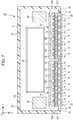
Fig. 3 is a sectional view taken along the line III-III of the liquid ejection section shown inFig. 2 . -
Fig. 4 is a descriptive view showing an operation of the liquid ejecting head of the embodiment. -
Fig. 5 is a descriptive view showing an operation of the liquid ejecting head of the embodiment. -
Fig. 6 is a sectional view showing a configuration of the liquid ejecting head according to a modification example of the first embodiment. -
Fig. 7 is a sectional view showing a configuration of the liquid ejecting head according to a second embodiment. -
Fig. 1 shows a first embodiment of the invention, in which a partial configuration of theliquid ejecting apparatus 10 is illustrated. Theliquid ejecting apparatus 10 of the first embodiment is an ink jet type printing apparatus that ejects ink, an example of a liquid, onto a medium 11 such as printing paper and the like. Theliquid ejecting apparatus 10 shown inFig. 1 includes acontrol device 12, atransport mechanism 15, acarriage 18, and aliquid ejecting head 20. Aliquid container 14 that stores ink is mounted on theliquid ejecting apparatus 10. - The
liquid container 14 is an ink tank type cartridge made of a box-shaped container attachable to and detachable from the main body of theliquid ejecting apparatus 10. Theliquid container 14 is not limited to a box-shaped container and may for example be an ink pack type cartridge made of a sack-shaped container. In theliquid container 14, ink is stored. The ink may be black ink or may be color ink. The ink stored in theliquid container 14 is pressure-fed to theliquid ejecting head 20. - The
control device 12 comprehensively controls each element of theliquid ejecting apparatus 10. Thetransport mechanism 15 transports the medium 11 in the Y-direction under the control of thecontrol device 12. Theliquid ejecting head 20 ejects ink supplied from theliquid container 14 onto the medium 11 from each of a plurality of the nozzles N under the control of thecontrol device 12. - The
liquid ejecting head 20 is mounted on thecarriage 18. InFig. 1 , a case where oneliquid ejecting head 20 is mounted on thecarriage 18 is presented as an example, but the invention is not limited thereto. A plurality of the liquid ejecting heads 20 may be mounted on thecarriage 18. Thecontrol device 12 causes thecarriage 18 to reciprocate in the X-direction which intersects with Y-direction (orthogonal inFig. 1 ). A desired image is formed on the surface of the medium 11 by ejecting ink from theliquid ejecting head 20 onto the medium 11 in concurrence with a repetition of the transport of the medium 11 and the reciprocation of thecarriage 18. A plurality of the liquid ejecting heads 20 may be mounted on thecarriage 18. - In the
liquid ejecting head 20, aliquid ejection section 70 is mounted. In theliquid ejection section 70, a nozzle row is disposed. The nozzle row is a collection of a plurality of nozzles N arranged in a straight line in the Y-direction. The ink supplied from theliquid container 14 is ejected from each nozzle N. The nozzle N of each nozzle row is formed on an ejection surface 22 (the surface facing the medium 11) of theliquid ejecting head 20. Further, the number and arrangement of theliquid ejection section 70 and the nozzle row are not limited to the example. For example, it is also possible to arrange a plurality of nozzle rows in a zigzag or staggered pattern on theejection surface 22 of theliquid ejecting head 20. The direction perpendicular to the X-Y plane (a plane parallel to the surface of medium 11) is denoted as the Z-direction. -
Fig. 2 shows a sectional view of theliquid ejecting head 20 shown inFig. 1 taken along the line II-II. As shown inFig. 2 , theliquid ejecting head 20 includes theliquid ejection section 70 and thecase member 30. Theliquid ejection section 70 is accommodated in thecase member 30. Specifically, anopening section 31 is formed on the positive side (downward inFig. 2 ) of the Z-direction of thecase member 30. Theliquid ejection section 70 is fixed to thecase member 30 so that theejection surface 22 is exposed from theopening section 31. Theliquid ejection section 70 includesejection sections 702 corresponding to each nozzle N. -
Fig. 3 shows a sectional view of theliquid ejection section 70 with a focus on onerandom ejection section 702. Theliquid ejection section 70 shown inFig. 3 is a structure in which thepressure chamber substrate 72, thediaphragm 73, thepiezoelectric element 74, and thesupport body 75 are disposed on one side of theflow path substrate 71 while thenozzle plate 76 is disposed on the other side thereof. Theflow path substrate 71, thepressure chamber substrate 72, and thenozzle plate 76 are each formed of a flat plate material of silicon for example, and thesupport body 75 is formed of a resin material by injection molding for example. Thepressure chamber substrate 72 anddiaphragm 73 may be provided integrally as in a case where a part of a member constituting thepressure chamber substrate 72 is thinned to function as thediaphragm 73. A plurality of the nozzles N are formed on thenozzle plate 76. In the configuration ofFig. 3 , the surface of thenozzle plate 76 facing the medium 11 constitutes theejection surface 22 of theliquid ejecting head 20. - On the
flow path substrate 71, theopening section 712, thebranch flow path 714, and thecommunication flow path 716 are formed. Thebranch flow path 714 and thecommunication flow path 716 are through holes formed for each nozzle N, and theopening section 712 is a continuous opening for a plurality of the nozzles N. The space in which the accommodation section 752 (recess portion) formed on thesupport body 75 and theopening section 712 of theflow path substrate 71 communicate with each other functions as the common liquid chamber SR (reservoir) that stores the ink supplied from theliquid container 14 through theintroduction flow path 754 of thesupport body 75. - On the
pressure chamber substrate 72, theopening section 722 is formed for each nozzle N. Thediaphragm 73 is an elastically deformable plate material disposed on the surface of thepressure chamber substrate 72, which is an opposite side to theflow path substrate 71. Space defined between thediaphragm 73 and theflow path substrate 71 inside eachopening section 722 of thepressure chamber substrate 72 functions as the pressure chamber SC (cavity) which is filled with ink supplied from the common liquid chamber SR through thebranch flow path 714. Each pressure chamber SC communicates with the nozzle N through thecommunication flow path 716 of theflow path substrate 71. - On the surface of the
diaphragm 73, opposite to thepressure chamber substrate 72, thepiezoelectric element 74 is formed for each nozzle N. Eachpiezoelectric element 74 is a driving element in which thepiezoelectric body 744 is interposed between the first electrode 742 and thesecond electrode 746. A driving signal is supplied to either one of the first electrode 742 and thesecond electrode 746, and a predetermined reference potential is supplied to the other. When thediaphragm 73 vibrates due to deformation of thepiezoelectric element 74 by the supply of the driving signal, pressure in the pressure chamber SC fluctuates and the ink in the pressure chamber SC is ejected from the nozzle N. Specifically, the ink is ejected from the nozzle N in the amount that corresponds to the amplitude of the driving signal. Oneejection section 702 shown inFig. 3 is a portion that includes thepiezoelectric element 74, thediaphragm 73, the pressure chamber SC, and the nozzle N. The configuration of thepiezoelectric element 74 is not limited to the above description. - As shown in
Figs. 2 and 3 , to protect thepiezoelectric element 74 and thediaphragm 73 from moisture, each of thepiezoelectric element 74 and thediaphragm 73 is accommodated in the first space S1 (accommodation space), and the first space S1 is sealed with the sealingbody 78. The sealingbody 78 according to the embodiment is a plate-shaped member having arecess portion 782 formed on the positive side in the Z-direction and is bonded to thediaphragm 73 with an adhesive or the like. The first space S1 is a space surrounded by therecess portion 782 of the sealingbody 78 and thediaphragm 73. The internal space of thecase member 30 functions as the second space S2 surrounding the sealingbody 78. - Meanwhile, if the first space S1 that accommodates the
piezoelectric element 74 and thediaphragm 73 communicates with the air, the moisture enters the first space S1 easily. When the moisture enters the first space S1 and thepiezoelectric element 74 is exposed to the humid environment for a long period of time, there is also a concern that the first electrode 742 and thesecond electrode 746 of thepiezoelectric element 74 corrode, or that the strength declines and cracking occurs due to a hydrolysis. Further, there is a concern that, if thediaphragm 73 is exposed to a highly humid environment for a long period of time, the strength of thediaphragm 73 also deteriorates and cracking occurs due to a hydrolysis. However, if the first space S1 is made a sealed space that does not communicate with atmosphere to prevent the moisture from entering the first space S1, a vibration of pressure chamber SC caused by driving of thepiezoelectric element 74 is propagated to the first space S1 and a pressure fluctuation also occurs in the first space S1. Since each pressure chamber SC is also affected by the pressure fluctuation of the first space S1, there is a concern that the ejection characteristic changes due to the pressure fluctuation of the first space S1 caused by such a structural crosstalk. The pressure fluctuation of the first space S1 also changes depending on the number of thepiezoelectric element 74 to be driven, causing a large difference in the pressure fluctuation gap, so that there is a concern that the ejection characteristic changes depending on the number of thepiezoelectric elements 74 to be driven. - Therefore, in the embodiment, as shown in
Fig. 2 , while anatmosphere vent 32 through which the second space S2 communicates with atmosphere is formed in thecase member 30, acommunication hole 784 through which the first space S1 communicates with the second space S2 is formed in the sealingbody 78, and amoisture absorber 40 is disposed in the second space S2. - In the configuration of
Fig. 2 , a case where the twomoisture absorbers 40 are disposed separated from each other in the Y-direction on a positive side surface in the X-direction of the inner circumferential surface F (inner wall surface in the vertical direction inFig. 2 ) of thecase member 30 is presented as an example. However, the number of themoisture absorbers 40 may be one, or three or more. Further, in the configuration ofFig. 2 , since thecircuit substrate 34 that drives thepiezoelectric element 74 on a positive side surface in the X-direction of the inner circumferential surface F of thecase member 30 is disposed, themoisture absorbers 40 are disposed on each side of the Y-direction across thecircuit substrate 34 one by one. According to such a configuration, thepiezoelectric element 74 and thediaphragm 73 can be protected from the moisture while the pressure fluctuation of the first space S1 that accommodates thepiezoelectric element 74 is suppressed. - Hereinafter, an operational effect according to the embodiment will be described with reference to the figures.
Figs. 4 and5 show an embodiment of theliquid ejecting head 20 showing an operation thereof.Fig. 4 shows a flow of the moisture that entered the second space S2 from theatmosphere vent 32 with an arrow.Fig. 5 shows a case where the water component of the moisture that entered the second space S2 from theatmosphere vent 32 condenses to adhere to the inner circumferential surface F of thecase member 30. - In the
liquid ejecting head 20 according to the embodiment, since the first space S1 that accommodates thepiezoelectric element 74 communicates through thecommunication hole 784 with the second space S2 that communicates with the air, the first space S1 can be prevented from becoming a sealed space. Therefore, since a fluctuation in pressure of the first space S1 that accommodates thepiezoelectric element 74 caused by the vibration of the pressure chamber SC can be suppressed, an ejection failure caused by the structural crosstalk can be reduced. Further, since themoisture absorber 40 is disposed in the second space S2, even if the moisture enters the second space S2 from theatmosphere vent 32 as shown inFig. 4 , the moisture is absorbed by themoisture absorber 40 in the second space S2. Therefore, since the moisture entering the first space S1 through thecommunication hole 784 can be reduced, thepiezoelectric element 74 and thediaphragm 73 can be protected from moisture. With this configuration, thepiezoelectric element 74 and thediaphragm 73 can be protected from the moisture while the pressure fluctuation of the first space S1 that accommodatespiezoelectric element 74 is suppressed. - Further, as shown in
Fig. 2 , according to the embodiment, since the opening area (sectional area orthogonal to Z-direction) of thecommunication hole 784 is smaller than the opening area (sectional area orthogonal to Z-direction) of theatmosphere vent 32, it is difficult for the moisture that entered the second space S2 from theatmosphere vent 32 to enter the first space S1 from thecommunication hole 784. The opening area of thecommunication hole 784 may be of any size such that the pressure vibration of the first space S1 can be suppressed at least to the extent that the first space S1 is not affected by the crosstalk described above. Further, a case where thecommunication hole 784 and theatmosphere vent 32 according to the embodiment are composed of the straight type openings is presented as an example, but the invention is not limited thereto. Thecommunication hole 784 and theatmosphere vent 32 may for example be openings that include an expanding diameter section or a shrinking diameter section in a taper-shaped form. In this case, by setting the minimum opening area ofcommunication hole 784 smaller than the minimum opening area of theatmosphere vent 32, it is possible to make it difficult for the moisture that entered the second space S2 from theatmosphere vent 32 to enter the first space S1 fromcommunication hole 784. - According to the embodiment, each of the two
moisture absorbers 40 is composed of the A-type silica gel that can maintain a stable absorption of the moisture even at a low temperature. However, themoisture absorber 40 may be anything that can absorb the moisture that entered the second space S2. According to the embodiment, themoisture absorber 40 composed of the A-type silica gel can absorb the moisture effectively even in an environment of low temperature. Themoisture absorber 40 may however be composed of the B-type silica gel or other moisture absorbing materials, for example. - Further, out of the two
moisture absorbers 40, one may be composed of the A-type silica gel and the other may be composed of a gas absorbent. The gas absorbent has higher absorption capacity than A-type silica gel and the like. Therefore, it is possible to absorb sulfur-based gas, chlorine-based gas and the like as well as the moisture that entered the second space S2 from theatmosphere vent 32. There is a concern that sulfur-based gas, chlorine-based gas, and the like corrode the electrical connection section, the first electrode 742 and thesecond electrode 746 of thepiezoelectric element 74, and the like in thecase member 30. According to the embodiment, since the sulfur-based gas and the chlorine-based gas are absorbed in the second space S2, the entry thereof into the first space S1 from thecommunication hole 784 can be suppressed. Therefore, thepiezoelectric element 74 can be protected from the sulfur-based gas and the chlorine-based gas that entered from theatmosphere vent 32. - Further, as shown in
Fig. 2 , according to the embodiment, since themoisture absorber 40 is in a position closer to thecommunication hole 784 than theatmosphere vent 32, compared with a case where themoisture absorbent 40 is in a position close to theatmosphere vent 32, it is possible to suppress suction of the moisture outside the second space S2 from theatmosphere vent 32 and absorption of that moisture. Therefore, the time during which hygroscopic capacity of themoisture absorber 40 can be maintained can be extended. Further, since themoisture absorber 40 is in a position close to thecommunication hole 784, compared with a case where themoisture absorber 40 is in a position away from thecommunication hole 784, it is possible to make it difficult for the moisture to enter fromcommunication hole 784. - Further, according to the embodiment, the
atmosphere vent 32 is in a position higher than thecommunication hole 784 in the vertical direction (Z-direction), and themoisture absorber 40 is disposed between theatmosphere vent 32 and thecommunication hole 784 in the vertical direction. With this configuration, as shown inFig. 5 , the water component of the moisture that entered the second space S2 from theatmosphere vent 32 condenses between theatmosphere vent 32 and thecommunication hole 784 due to a temperature drop, and the dew condensation droplet Hd adheres to the inner circumferential surface F of thecase member 30 in some cases. Then, there is a concern that the dew condensation droplet Hd evaporates to raise the moisture high when the temperature rises again thereafter. However, when the dew condensation droplet Hd evaporates, the water component rises up in the vertical direction (wavy arrow line ofFig. 6 ), so that the moisture can be absorbed efficiently by themoisture absorber 40 disposed between theatmosphere vent 32 and thecommunication hole 784. Therefore, even if the dew condensation droplet Hd evaporates on the inner circumferential surface F of thecase member 30, entry of the moisture intocommunication hole 784 can be suppressed so that the reliability of the apparatus even in a highly humid environment can be maintained. - Further, as shown in
Fig. 5 , according to the embodiment, the second space S2 includes the recess portion S21 that includes thebottom surface 36 positioned lower than thecommunication hole 784 in the vertical direction. The recess portion S21 ofFig. 5 , disposed around theliquid ejection section 70, is a ring-shaped groove surrounded by the outer circumferential surface (the surface in Z-direction) of theliquid ejection section 70, a part of the inner circumferential surface F of thecase member 30 that faces the outer circumference surface of theliquid ejection section 70, and thebottom surface 36. With this configuration, as shown inFig. 5 , the second space S2 can trap the dew condensation droplet Hd in the recess portion S21 even if the dew condensation droplet Hd adhering to the inner circumferential surface F of thecase member 30 moves downward along the inner circumferential surface of thecase member 30. Further, since the recess portion S21 has thebottom surface 36 positioned lower than thecommunication hole 784 in the vertical direction, the dew condensation droplet Hd can be stored in the recess portion S21 positioned lower than thecommunication hole 784, and thus, entry of the dew condensation droplet Hd into thecommunication hole 784 can be suppressed. Further, the shape of the recess portion S21 may not be annular. Further, the position of the recess portion S21 is not limited to the circumference of theliquid ejection section 70. - According to the embodiment, the material of the
case member 30 has higher thermal conductivity than the sealingbody 78. With this configuration, when a temperature falls, the water component of the moisture that entered the second space S2 can be condensed actively on the inner circumferential surface F of thecase member 30 in the second space S2. Therefore, since the moisture of the first space S1 can be lowered, the dew condensation can be made difficult in the first space S1. Further, when a temperature rises, the dew condensation droplet Hd condensed on the inner circumferential surface F of thecase member 30 evaporates again in the second space S2, so that the moisture is absorbed by themoisture absorber 40 easily. Further, thecase member 30 may be made of a resin material, so that a coating layer that suppresses permeation of the water component may be formed on the inner circumferential surface F. As for the coating layer, a material that easily condenses moisture, for example, a moisture-proof coating material like Fluorosurf (registered trademark of Fluoro Technology Co., Ltd.) and the like, may be considered.
With this configuration, thecase member 30 that can actively condense the moisture on the inner circumferential surface F of thecase member 30 can be manufactured at low cost. - Further, as shown in
Fig. 2 , according to the embodiment, thecircuit substrate 34 that can be a heat source is disposed in the second space S2, so that the temperature of the second space S2 rises more easily than the temperature of the first space S1, and thus, the permissible volume of the saturated water component in the second space S2 increases, and the evaporation volume of the water component increases easily. According to the embodiment, since themoisture absorber 40 is present in the second space S2 where thecircuit substrate 34 of which the ambient temperature rises easily is disposed, the moisture of the second space S2, where the evaporation volume of the water component increases easily, can be absorbed efficiently. - Further, according to the embodiment, the volume of the first space S1 is smaller than the volume of the second space S2. For example, the volume of the first space S1 is 1 to 10mm3, while the volume of the second space S2 is 10,000 to 400,000mm3. In this way, the smaller the volume of the first space S1 with respect to the volume of the second space S2, the smaller the dew condensation amount in the first space S1 can be made considerably than the dew condensation amount in the second space S2 even if dew condensation occurs. Therefore, the characteristic deterioration of the
piezoelectric element 74 caused by the dew condensation can be reduced. Conversely, since the volume of the second space S2 is larger than the volume of the first space S1, the volume of themoisture absorber 40 disposed in the second space S2 may be easily increased, and thus, the hygroscopic effect by themoisture absorber 40 can be enhanced. -
Fig. 6 shows a sectional view of the configuration of theliquid ejecting head 20 according to a modification example of the first embodiment (the modification example itself being an embodiment of the present invention) and corresponds toFig. 2 . Thecase member 30 ofFig. 6 includes alower case member 302 on the lower side in the vertical direction and anupper case member 304 on an upper side higher than thelower case member 302 in the vertical direction. Thelower case member 302 and theupper case member 304 are bonded together with an adhesive or the like. Themoisture absorber 40 inFig. 6 is disposed on theupper case member 304, and thelower case member 302 has a higher thermal conductivity than theupper case member 304. - According to the configuration of
Fig. 6 , since thelower case member 302 that constitutes thecase member 30 has a higher thermal conductivity than theupper case member 304, when a temperature falls, the water component of the moisture that entered the second space S2 can condense more easily in thelower case member 302 than theupper case member 304. Therefore, when a temperature rises, the dew condensation droplet Hd adhering to thelower case member 302 evaporates again to rise up and is absorbed easily by themoisture absorber 40 disposed in the upper case member 304 (wavy arrow line inFig. 6 ). Further, the dew condensation droplet Hd that moves downward along the inner circumferential surface F of thelower case member 302 is trapped easily in the recess portion S21 (straight arrow line inFig. 6 ). Further, inFig. 6 , a case where thelower case member 302 and theupper case member 304 are bonded together is presented as an example, but the invention is not limited thereto. For example, another member (for example, a sealing member for sealing the second space S2) may be interposed between thelower case member 302 and theupper case member 304. - A second embodiment of the invention will be described. For the element that has the same operation and function as in the first embodiment in each form presented below, reference numerals used in the description of the first embodiment will be used and the detailed description thereof will be omitted as deemed appropriate. In the second embodiment, the
liquid ejecting head 20 that includes a plurality of theliquid ejection sections 70 will be presented as an example. -
Fig. 7 shows a sectional view of the configuration ofliquid ejecting head 20 according to the second embodiment and corresponds toFig. 2 . Theliquid ejecting head 20 ofFig. 7 includes twoliquid ejection sections 70 in the second space S2. InFig. 7 , a case where the twoliquid ejection sections 70 are arranged side by side in the Y-direction is presented as an example, but a plurality of theliquid ejection sections 70 may for example be arranged in a zigzag manner. Thecommunication hole 784 ofFig. 7 is provided corresponding to each of the first spaces S1, and each of the first spaces S1 communicates with the second space S2. Themoisture absorber 40 ofFig. 7 is present in the second space S2, and onemoisture absorber 40 is provided in the vicinity of each of the communication holes 784. - In the
liquid ejecting head 20 of the second embodiment with such a configuration, since entry of the moisture into each of the first spaces S1 from each of the communication holes 784 can be suppressed by themoisture absorber 40 disposed in the second space S2, compared with the case where a second space S2 is provided for each of the first spaces S1 and the moisture absorber is disposed in each of the second spaces S2, the structure of thecase member 30 can be simplified. Further, since the second space S2 becomes a common communication space to each of the first spaces S1, compared with the case where a second space S2 is provided for each of the first space S1, the volume of the second space S2 can be enlarged considerably. Therefore, the hygroscopic effect of themoisture absorber 40 can be enhanced by increasing themoisture absorber 40 disposed in the second space S2 easily. Modification Example - The aspects and the embodiments described above can be modified variously. Specific modifications of aspects, each themselves being further exemplary embodiments of the invention, are presented below. Two or more aspects randomly selected from the aspects presented below and described above can be properly merged within a scope where the aspects do not contradict one another.
- (1) In the embodiment described above, a serial head that causes the
carriage 18 on which theliquid ejecting head 20 is mounted to reciprocate repeatedly in X-direction is presented as an example. However, the invention is also applicable for example to a line head in which the liquid ejecting heads 20 are arranged over the entire width ofmedium 11. - (2) In the embodiment described above, the
liquid ejecting head 20 of the piezoelectric type using the piezoelectric element that applies a mechanical vibration to the pressure chamber is presented as an example. However, it is also possible to adopt, for example, a thermal type liquid ejecting head using a heat generating element that generates the air bubbles inside the pressure chamber by heating. - (3) The
liquid ejecting apparatus 10 exemplified by the embodiment described above can be adopted in various machines like a facsimile apparatus and a copy machine in addition to the machine specialized in printing. Use of theliquid ejecting apparatus 10 of the invention is not limited to printing. For example, a liquid ejecting apparatus that ejects a solution of a coloring material is used as a manufacturing apparatus for forming a color filter of a liquid crystal display device, an organic electroluminescence (EL) display, a field emission display (FED), and the like. Further, the present invention may for example be applied to a liquid ejecting apparatus that ejects a solution of a conductive material and which is used as a manufacturing apparatus for forming wirings and electrodes of wiring substrates, or for example to a chip manufacturing apparatus for ejecting a solution of bioorganic matter as a kind of liquid. - The foregoing description has been given by way of example only and it will be appreciated by a person skilled in the art that modifications can be made without departing from the scope of the present invention as defined by the claims.
Claims (11)
- A liquid ejecting head (20) comprising:a driving element (74) that causes a liquid to be ejected from a nozzle (N) by fluctuating a pressure of a pressure chamber (SC) filled with the liquid;a sealing body (78) that forms a first space (S1) for accommodating the driving element;a case member (30) that forms a second space (S2) for surrounding the sealing body;an atmosphere vent (32) that is formed in the case member and through which the second space communicates with atmosphere;a communication hole (784) that is formed in the sealing body and through which the first space communicates with the second space; anda moisture absorber (40) in the second space.
- The liquid ejecting head (20) according to Claim 1,
wherein the moisture absorber is in a position closer to the communication hole than to the atmosphere vent. - The liquid ejecting head (20) according to Claim 1 or Claim 2,
wherein the atmosphere vent is in a position higher than the communication hole in a vertical direction, and
the moisture absorber is disposed between the atmosphere vent and the communication hole in the vertical direction. - The liquid ejecting head (20) according to any one of the preceding claims,
wherein the second space includes a recess portion (S21) that has a bottom surface (36) positioned lower than the communication hole in the vertical direction. - The liquid ejecting head (20) according to any one of the preceding claims,
wherein the case member has a higher thermal conductivity than the sealing body. - The liquid ejecting head (20) according to any one of the preceding claims,
wherein the case member includes at least a lower case member (302) on a lower side in the vertical direction and an upper case member (304) on an upper side higher than the lower case member in the vertical direction,
the moisture absorber is disposed in the upper case member, and
the lower case member has a higher thermal conductivity than the upper case member. - The liquid ejecting head (20) according to any one of the preceding claims,
wherein a minimum opening area of the communication hole is smaller than a minimum opening area of the atmosphere vent. - The liquid ejecting head (20) according to any one of the preceding claims, wherein a volume of the first space is smaller than a volume of the second space.
- The liquid ejecting head (20) according to any one of the preceding claims,
wherein a circuit substrate (34) is disposed in the second space. - The liquid ejecting head (20) according to any one of the preceding claims,
wherein a plurality of the sealing bodies (78) are provided,
a communication hole (784) is provided corresponding to each of the sealing bodies, and
the first space (S1) of each of the sealing bodies and the second space (S2) communicate with each other through each of the communication holes. - A liquid ejecting apparatus (10) comprising:
the liquid ejecting head (20) according to any one of the preceding claims.
Applications Claiming Priority (1)
| Application Number | Priority Date | Filing Date | Title |
|---|---|---|---|
| JP2017250936A JP7006262B2 (en) | 2017-12-27 | 2017-12-27 | Liquid discharge head and liquid discharge device |
Publications (1)
| Publication Number | Publication Date |
|---|---|
| EP3505350A1 true EP3505350A1 (en) | 2019-07-03 |
Family
ID=65011793
Family Applications (1)
| Application Number | Title | Priority Date | Filing Date |
|---|---|---|---|
| EP18248129.1A Withdrawn EP3505350A1 (en) | 2017-12-27 | 2018-12-28 | Liquid ejecting head and liquid ejecting apparatus |
Country Status (4)
| Country | Link |
|---|---|
| US (1) | US10654266B2 (en) |
| EP (1) | EP3505350A1 (en) |
| JP (1) | JP7006262B2 (en) |
| CN (1) | CN109968814B (en) |
Citations (13)
| Publication number | Priority date | Publication date | Assignee | Title |
|---|---|---|---|---|
| US20020130930A1 (en) * | 2001-03-08 | 2002-09-19 | Seiko Epson Corporation | Ink-jet recording head and ink-jet recording apparatus |
| US20030234834A1 (en) * | 2002-06-21 | 2003-12-25 | Takanori Nakano | Piezoelectric actuator and method of manufacture therefor, and ink jet head and ink jet type recording device |
| JP2005074966A (en) * | 2003-09-03 | 2005-03-24 | Seiko Epson Corp | Liquid ejecting head, liquid ejecting apparatus, and liquid ejecting head ventilation method |
| US20050285909A1 (en) * | 2004-06-29 | 2005-12-29 | Fuji Xerox Co., Ltd. | Liquid droplet ejecting head and liquid droplet ejecting apparatus |
| JP2006255973A (en) * | 2005-03-15 | 2006-09-28 | Fuji Xerox Co Ltd | Droplet discharging head, and droplet discharging device |
| JP2007276184A (en) * | 2006-04-04 | 2007-10-25 | Matsushita Electric Ind Co Ltd | Ink jet head and ink jet recording apparatus |
| US20070291083A1 (en) * | 2006-06-19 | 2007-12-20 | Matsushita Electric Industrial Co., Ltd. | Ink jet head unit, ink jet recording apparatus, and method of manufacturing ink jet head |
| EP1953839A1 (en) * | 2007-01-30 | 2008-08-06 | Matsushita Electric Industrial Co., Ltd. | Piezoelectric Element, Ink Jet Head, and Ink Jet Recording Device |
| US20110139901A1 (en) * | 2009-12-14 | 2011-06-16 | Fujifilm Corporation | Moisture Protection Of Fluid Ejector |
| JP2011135001A (en) * | 2009-12-25 | 2011-07-07 | Fujifilm Corp | Piezoelectric element, and ink jet head and ink jet recording device |
| JP2011131549A (en) * | 2009-12-25 | 2011-07-07 | Fujifilm Corp | Piezoelectric element and inkjet head, and inkjet recording apparatus |
| US9016835B1 (en) * | 2013-11-08 | 2015-04-28 | Xerox Corporation | MEMS actuator pressure compensation structure for decreasing humidity |
| JP2016000500A (en) | 2014-06-12 | 2016-01-07 | セイコーエプソン株式会社 | Liquid jetting head, liquid jetting device and method for manufacturing liquid jetting head |
Family Cites Families (12)
| Publication number | Priority date | Publication date | Assignee | Title |
|---|---|---|---|---|
| JP2005131888A (en) | 2003-10-29 | 2005-05-26 | Seiko Epson Corp | Liquid ejecting head and liquid ejecting apparatus |
| US7344220B2 (en) * | 2005-01-25 | 2008-03-18 | Fujifilm Dimatix, Inc. | Ink jet printing apparatus having non-contact print head maintenance station |
| JP5011792B2 (en) * | 2006-04-04 | 2012-08-29 | 凸版印刷株式会社 | LAMINATE MANUFACTURING METHOD AND PACKAGING BAG MANUFACTURING METHOD |
| CN2892472Y (en) * | 2006-04-05 | 2007-04-25 | 陈小恩 | Spray drawing, printing drawing machine spray head humidifying device |
| US8147040B2 (en) | 2009-02-27 | 2012-04-03 | Fujifilm Corporation | Moisture protection of fluid ejector |
| JP5426257B2 (en) | 2009-07-03 | 2014-02-26 | 富士フイルム株式会社 | Lens barrel shift mechanism and projector |
| JP5768393B2 (en) * | 2011-02-10 | 2015-08-26 | 株式会社リコー | Ink jet head and image forming apparatus |
| US9162453B2 (en) | 2012-07-30 | 2015-10-20 | Hewlett-Packard Development Company, L.P. | Printhead including integrated circuit die cooling |
| JP6057063B2 (en) | 2012-09-11 | 2017-01-11 | セイコーエプソン株式会社 | Liquid ejecting head and liquid ejecting apparatus |
| JP6447819B2 (en) * | 2015-03-10 | 2019-01-09 | セイコーエプソン株式会社 | Head and liquid ejecting apparatus |
| JP2016199618A (en) * | 2015-04-07 | 2016-12-01 | キヤノン株式会社 | Ink, ink cartridge, and inkjet recording method |
| JP6859594B2 (en) | 2016-02-10 | 2021-04-14 | セイコーエプソン株式会社 | Liquid injection head and liquid injection head unit |
-
2017
- 2017-12-27 JP JP2017250936A patent/JP7006262B2/en active Active
-
2018
- 2018-12-24 CN CN201811581673.5A patent/CN109968814B/en active Active
- 2018-12-27 US US16/233,380 patent/US10654266B2/en active Active
- 2018-12-28 EP EP18248129.1A patent/EP3505350A1/en not_active Withdrawn
Patent Citations (13)
| Publication number | Priority date | Publication date | Assignee | Title |
|---|---|---|---|---|
| US20020130930A1 (en) * | 2001-03-08 | 2002-09-19 | Seiko Epson Corporation | Ink-jet recording head and ink-jet recording apparatus |
| US20030234834A1 (en) * | 2002-06-21 | 2003-12-25 | Takanori Nakano | Piezoelectric actuator and method of manufacture therefor, and ink jet head and ink jet type recording device |
| JP2005074966A (en) * | 2003-09-03 | 2005-03-24 | Seiko Epson Corp | Liquid ejecting head, liquid ejecting apparatus, and liquid ejecting head ventilation method |
| US20050285909A1 (en) * | 2004-06-29 | 2005-12-29 | Fuji Xerox Co., Ltd. | Liquid droplet ejecting head and liquid droplet ejecting apparatus |
| JP2006255973A (en) * | 2005-03-15 | 2006-09-28 | Fuji Xerox Co Ltd | Droplet discharging head, and droplet discharging device |
| JP2007276184A (en) * | 2006-04-04 | 2007-10-25 | Matsushita Electric Ind Co Ltd | Ink jet head and ink jet recording apparatus |
| US20070291083A1 (en) * | 2006-06-19 | 2007-12-20 | Matsushita Electric Industrial Co., Ltd. | Ink jet head unit, ink jet recording apparatus, and method of manufacturing ink jet head |
| EP1953839A1 (en) * | 2007-01-30 | 2008-08-06 | Matsushita Electric Industrial Co., Ltd. | Piezoelectric Element, Ink Jet Head, and Ink Jet Recording Device |
| US20110139901A1 (en) * | 2009-12-14 | 2011-06-16 | Fujifilm Corporation | Moisture Protection Of Fluid Ejector |
| JP2011135001A (en) * | 2009-12-25 | 2011-07-07 | Fujifilm Corp | Piezoelectric element, and ink jet head and ink jet recording device |
| JP2011131549A (en) * | 2009-12-25 | 2011-07-07 | Fujifilm Corp | Piezoelectric element and inkjet head, and inkjet recording apparatus |
| US9016835B1 (en) * | 2013-11-08 | 2015-04-28 | Xerox Corporation | MEMS actuator pressure compensation structure for decreasing humidity |
| JP2016000500A (en) | 2014-06-12 | 2016-01-07 | セイコーエプソン株式会社 | Liquid jetting head, liquid jetting device and method for manufacturing liquid jetting head |
Also Published As
| Publication number | Publication date |
|---|---|
| US10654266B2 (en) | 2020-05-19 |
| JP7006262B2 (en) | 2022-01-24 |
| JP2019116004A (en) | 2019-07-18 |
| CN109968814A (en) | 2019-07-05 |
| CN109968814B (en) | 2020-12-15 |
| US20190193397A1 (en) | 2019-06-27 |
Similar Documents
| Publication | Publication Date | Title |
|---|---|---|
| JP7230980B2 (en) | Liquid ejection head and liquid ejection device | |
| JP7069909B2 (en) | Liquid discharge head and liquid discharge device | |
| US8449094B2 (en) | Liquid ejection head unit and liquid ejection apparatus | |
| US20170225457A1 (en) | Liquid ejecting head and liquid ejecting apparatus | |
| JP5839159B2 (en) | Liquid ejecting head and liquid ejecting apparatus | |
| JP2013035163A (en) | Liquid ejecting head and liquid ejecting apparatus | |
| US9211711B2 (en) | Liquid ejecting head and liquid ejecting apparatus | |
| US20130147882A1 (en) | Liquid Ejecting Head and Liquid Ejecting Apparatus | |
| US10654266B2 (en) | Liquid ejecting head and liquid ejecting apparatus | |
| JP2011224780A (en) | Liquid ejector and liquid ejection head | |
| US10836161B2 (en) | Liquid ejecting head and liquid ejecting apparatus | |
| US9327501B2 (en) | Inkjet-head and ink jet printer | |
| US10449765B2 (en) | Liquid ejecting head and liquid ejecting apparatus | |
| US9434162B2 (en) | Liquid ejecting head and liquid ejecting apparatus | |
| US10723129B2 (en) | Liquid ejecting head and liquid ejecting apparatus | |
| JP7259395B2 (en) | Liquid ejecting head and liquid ejecting device | |
| US10828895B2 (en) | Precision instrument, moisture absorbent used therefor, manufacturing method of moisture absorbent, and manufacturing method of precision instrument | |
| US20150375506A1 (en) | Inkjet-head and ink jet printer | |
| JP5691218B2 (en) | Liquid ejecting apparatus and liquid ejecting head | |
| JP6268460B2 (en) | Liquid ejecting head and liquid ejecting apparatus |
Legal Events
| Date | Code | Title | Description |
|---|---|---|---|
| PUAI | Public reference made under article 153(3) epc to a published international application that has entered the european phase |
Free format text: ORIGINAL CODE: 0009012 |
|
| AK | Designated contracting states |
Kind code of ref document: A1 Designated state(s): AL AT BE BG CH CY CZ DE DK EE ES FI FR GB GR HR HU IE IS IT LI LT LU LV MC MK MT NL NO PL PT RO RS SE SI SK SM TR |
|
| AX | Request for extension of the european patent |
Extension state: BA ME |
|
| STAA | Information on the status of an ep patent application or granted ep patent |
Free format text: STATUS: THE APPLICATION IS DEEMED TO BE WITHDRAWN |
|
| 18D | Application deemed to be withdrawn |
Effective date: 20200104 |