EP3505057B1 - Apparatus and method of assessing a narrowing in a fluid filled tube - Google Patents
Apparatus and method of assessing a narrowing in a fluid filled tube Download PDFInfo
- Publication number
- EP3505057B1 EP3505057B1 EP18206377.6A EP18206377A EP3505057B1 EP 3505057 B1 EP3505057 B1 EP 3505057B1 EP 18206377 A EP18206377 A EP 18206377A EP 3505057 B1 EP3505057 B1 EP 3505057B1
- Authority
- EP
- European Patent Office
- Prior art keywords
- pressure
- originating
- backward
- window
- narrowing
- Prior art date
- Legal status (The legal status is an assumption and is not a legal conclusion. Google has not performed a legal analysis and makes no representation as to the accuracy of the status listed.)
- Active
Links
- 238000000034 method Methods 0.000 title claims description 27
- 239000012530 fluid Substances 0.000 title claims description 25
- 238000005259 measurement Methods 0.000 claims description 43
- 238000009530 blood pressure measurement Methods 0.000 claims description 26
- 230000000747 cardiac effect Effects 0.000 claims description 24
- 210000004204 blood vessel Anatomy 0.000 claims description 7
- 125000004122 cyclic group Chemical group 0.000 claims description 7
- 230000036772 blood pressure Effects 0.000 claims description 5
- 230000002045 lasting effect Effects 0.000 claims description 3
- 239000000523 sample Substances 0.000 description 16
- 238000004458 analytical method Methods 0.000 description 10
- 229940124549 vasodilator Drugs 0.000 description 7
- 239000003071 vasodilator agent Substances 0.000 description 7
- 206010020565 Hyperaemia Diseases 0.000 description 6
- 208000031481 Pathologic Constriction Diseases 0.000 description 5
- 230000036262 stenosis Effects 0.000 description 5
- 208000037804 stenosis Diseases 0.000 description 5
- OIRDTQYFTABQOQ-KQYNXXCUSA-N adenosine Chemical compound C1=NC=2C(N)=NC=NC=2N1[C@@H]1O[C@H](CO)[C@@H](O)[C@H]1O OIRDTQYFTABQOQ-KQYNXXCUSA-N 0.000 description 4
- 238000010586 diagram Methods 0.000 description 3
- 230000001435 haemodynamic effect Effects 0.000 description 3
- 230000002792 vascular Effects 0.000 description 3
- 239000002126 C01EB10 - Adenosine Substances 0.000 description 2
- 208000007177 Left Ventricular Hypertrophy Diseases 0.000 description 2
- 229960005305 adenosine Drugs 0.000 description 2
- 239000008280 blood Substances 0.000 description 2
- 210000004369 blood Anatomy 0.000 description 2
- 238000004891 communication Methods 0.000 description 2
- 238000013500 data storage Methods 0.000 description 2
- 230000003902 lesion Effects 0.000 description 2
- 210000004165 myocardium Anatomy 0.000 description 2
- 230000003389 potentiating effect Effects 0.000 description 2
- 238000005070 sampling Methods 0.000 description 2
- 230000002861 ventricular Effects 0.000 description 2
- 206010002329 Aneurysm Diseases 0.000 description 1
- 201000000057 Coronary Stenosis Diseases 0.000 description 1
- 230000002238 attenuated effect Effects 0.000 description 1
- 230000009286 beneficial effect Effects 0.000 description 1
- 230000017531 blood circulation Effects 0.000 description 1
- 238000012512 characterization method Methods 0.000 description 1
- 230000004087 circulation Effects 0.000 description 1
- 150000001875 compounds Chemical class 0.000 description 1
- 230000006835 compression Effects 0.000 description 1
- 238000007906 compression Methods 0.000 description 1
- 230000008602 contraction Effects 0.000 description 1
- 210000004351 coronary vessel Anatomy 0.000 description 1
- 238000001514 detection method Methods 0.000 description 1
- 238000002059 diagnostic imaging Methods 0.000 description 1
- 230000003205 diastolic effect Effects 0.000 description 1
- IZEKFCXSFNUWAM-UHFFFAOYSA-N dipyridamole Chemical compound C=12N=C(N(CCO)CCO)N=C(N3CCCCC3)C2=NC(N(CCO)CCO)=NC=1N1CCCCC1 IZEKFCXSFNUWAM-UHFFFAOYSA-N 0.000 description 1
- 229960002768 dipyridamole Drugs 0.000 description 1
- 230000002526 effect on cardiovascular system Effects 0.000 description 1
- 230000000694 effects Effects 0.000 description 1
- 230000005284 excitation Effects 0.000 description 1
- 230000000977 initiatory effect Effects 0.000 description 1
- 238000001361 intraarterial administration Methods 0.000 description 1
- 230000004807 localization Effects 0.000 description 1
- 239000003550 marker Substances 0.000 description 1
- 230000004089 microcirculation Effects 0.000 description 1
- 230000010355 oscillation Effects 0.000 description 1
- 239000012466 permeate Substances 0.000 description 1
- 230000001902 propagating effect Effects 0.000 description 1
- 238000000926 separation method Methods 0.000 description 1
- 230000002966 stenotic effect Effects 0.000 description 1
- CCEKAJIANROZEO-UHFFFAOYSA-N sulfluramid Chemical group CCNS(=O)(=O)C(F)(F)C(F)(F)C(F)(F)C(F)(F)C(F)(F)C(F)(F)C(F)(F)C(F)(F)F CCEKAJIANROZEO-UHFFFAOYSA-N 0.000 description 1
- 239000002550 vasoactive agent Substances 0.000 description 1
Images
Classifications
-
- A—HUMAN NECESSITIES
- A61—MEDICAL OR VETERINARY SCIENCE; HYGIENE
- A61B—DIAGNOSIS; SURGERY; IDENTIFICATION
- A61B5/00—Measuring for diagnostic purposes; Identification of persons
- A61B5/02—Detecting, measuring or recording pulse, heart rate, blood pressure or blood flow; Combined pulse/heart-rate/blood pressure determination; Evaluating a cardiovascular condition not otherwise provided for, e.g. using combinations of techniques provided for in this group with electrocardiography or electroauscultation; Heart catheters for measuring blood pressure
- A61B5/021—Measuring pressure in heart or blood vessels
-
- A—HUMAN NECESSITIES
- A61—MEDICAL OR VETERINARY SCIENCE; HYGIENE
- A61B—DIAGNOSIS; SURGERY; IDENTIFICATION
- A61B5/00—Measuring for diagnostic purposes; Identification of persons
- A61B5/02—Detecting, measuring or recording pulse, heart rate, blood pressure or blood flow; Combined pulse/heart-rate/blood pressure determination; Evaluating a cardiovascular condition not otherwise provided for, e.g. using combinations of techniques provided for in this group with electrocardiography or electroauscultation; Heart catheters for measuring blood pressure
- A61B5/02007—Evaluating blood vessel condition, e.g. elasticity, compliance
-
- A—HUMAN NECESSITIES
- A61—MEDICAL OR VETERINARY SCIENCE; HYGIENE
- A61B—DIAGNOSIS; SURGERY; IDENTIFICATION
- A61B5/00—Measuring for diagnostic purposes; Identification of persons
- A61B5/02—Detecting, measuring or recording pulse, heart rate, blood pressure or blood flow; Combined pulse/heart-rate/blood pressure determination; Evaluating a cardiovascular condition not otherwise provided for, e.g. using combinations of techniques provided for in this group with electrocardiography or electroauscultation; Heart catheters for measuring blood pressure
- A61B5/021—Measuring pressure in heart or blood vessels
- A61B5/02108—Measuring pressure in heart or blood vessels from analysis of pulse wave characteristics
- A61B5/02125—Measuring pressure in heart or blood vessels from analysis of pulse wave characteristics of pulse wave propagation time
-
- A—HUMAN NECESSITIES
- A61—MEDICAL OR VETERINARY SCIENCE; HYGIENE
- A61B—DIAGNOSIS; SURGERY; IDENTIFICATION
- A61B5/00—Measuring for diagnostic purposes; Identification of persons
- A61B5/02—Detecting, measuring or recording pulse, heart rate, blood pressure or blood flow; Combined pulse/heart-rate/blood pressure determination; Evaluating a cardiovascular condition not otherwise provided for, e.g. using combinations of techniques provided for in this group with electrocardiography or electroauscultation; Heart catheters for measuring blood pressure
- A61B5/021—Measuring pressure in heart or blood vessels
- A61B5/0215—Measuring pressure in heart or blood vessels by means inserted into the body
-
- A—HUMAN NECESSITIES
- A61—MEDICAL OR VETERINARY SCIENCE; HYGIENE
- A61B—DIAGNOSIS; SURGERY; IDENTIFICATION
- A61B5/00—Measuring for diagnostic purposes; Identification of persons
- A61B5/02—Detecting, measuring or recording pulse, heart rate, blood pressure or blood flow; Combined pulse/heart-rate/blood pressure determination; Evaluating a cardiovascular condition not otherwise provided for, e.g. using combinations of techniques provided for in this group with electrocardiography or electroauscultation; Heart catheters for measuring blood pressure
- A61B5/026—Measuring blood flow
- A61B5/0285—Measuring or recording phase velocity of blood waves
-
- A—HUMAN NECESSITIES
- A61—MEDICAL OR VETERINARY SCIENCE; HYGIENE
- A61B—DIAGNOSIS; SURGERY; IDENTIFICATION
- A61B5/00—Measuring for diagnostic purposes; Identification of persons
- A61B5/103—Detecting, measuring or recording devices for testing the shape, pattern, colour, size or movement of the body or parts thereof, for diagnostic purposes
- A61B5/107—Measuring physical dimensions, e.g. size of the entire body or parts thereof
- A61B5/1076—Measuring physical dimensions, e.g. size of the entire body or parts thereof for measuring dimensions inside body cavities, e.g. using catheters
-
- A—HUMAN NECESSITIES
- A61—MEDICAL OR VETERINARY SCIENCE; HYGIENE
- A61B—DIAGNOSIS; SURGERY; IDENTIFICATION
- A61B5/00—Measuring for diagnostic purposes; Identification of persons
- A61B5/72—Signal processing specially adapted for physiological signals or for diagnostic purposes
- A61B5/7235—Details of waveform analysis
- A61B5/7264—Classification of physiological signals or data, e.g. using neural networks, statistical classifiers, expert systems or fuzzy systems
-
- A—HUMAN NECESSITIES
- A61—MEDICAL OR VETERINARY SCIENCE; HYGIENE
- A61B—DIAGNOSIS; SURGERY; IDENTIFICATION
- A61B5/00—Measuring for diagnostic purposes; Identification of persons
- A61B5/72—Signal processing specially adapted for physiological signals or for diagnostic purposes
- A61B5/7271—Specific aspects of physiological measurement analysis
- A61B5/7278—Artificial waveform generation or derivation, e.g. synthesising signals from measured signals
-
- A—HUMAN NECESSITIES
- A61—MEDICAL OR VETERINARY SCIENCE; HYGIENE
- A61B—DIAGNOSIS; SURGERY; IDENTIFICATION
- A61B5/00—Measuring for diagnostic purposes; Identification of persons
- A61B5/02—Detecting, measuring or recording pulse, heart rate, blood pressure or blood flow; Combined pulse/heart-rate/blood pressure determination; Evaluating a cardiovascular condition not otherwise provided for, e.g. using combinations of techniques provided for in this group with electrocardiography or electroauscultation; Heart catheters for measuring blood pressure
- A61B5/026—Measuring blood flow
-
- A—HUMAN NECESSITIES
- A61—MEDICAL OR VETERINARY SCIENCE; HYGIENE
- A61B—DIAGNOSIS; SURGERY; IDENTIFICATION
- A61B5/00—Measuring for diagnostic purposes; Identification of persons
- A61B5/68—Arrangements of detecting, measuring or recording means, e.g. sensors, in relation to patient
- A61B5/6846—Arrangements of detecting, measuring or recording means, e.g. sensors, in relation to patient specially adapted to be brought in contact with an internal body part, i.e. invasive
- A61B5/6847—Arrangements of detecting, measuring or recording means, e.g. sensors, in relation to patient specially adapted to be brought in contact with an internal body part, i.e. invasive mounted on an invasive device
- A61B5/6852—Catheters
Definitions
- This invention relates to an apparatus and method of assessing a narrowing in a fluid filled tube.
- a fluid filled tube or vessel formed with a constriction or narrowing can be analyzed to measure the magnitude of the constriction or narrowing.
- An example of a fluid filled tube or vessel formed with a constriction or narrowing is a blood vessel having a stenosis. Assessment or measurement of the constriction can result in a useful parameter to gauge the extent of the constriction.
- FFR fractional flow reserve
- Distal pressure arises from resistance of the microcirculation, in addition to active compression of small microcirculatory vessels, which permeate the myocardium.
- backward-originating pressure 1 2 dP + ⁇ c dU
- dP ⁇ 1 2 dP ⁇ ⁇ c dU
- dP is the differential of pressure
- ⁇ density of blood
- c wave speed
- dU is the differential of flow velocity.
- One aspect of the present invention is a method of assessing a narrowing in a fluid filled tube being a blood vessel of a cyclic fluid flow system, in particular a cardiac environment comprising: receiving from a storage device previously taken measurements of blood pressure waveform during a cardiac cycle on either side of the narrowing; separating the pressure components into the backward-originating pressure component and the forward-originating pressure component; identifying from the pressure-only measurements a time window when the differential of flow velocity is minimal or absent; deriving the backward- and forward-originating pressure components from the pressure measurements for the time window using the pressure waveform alone, dispensing with the need for measurement of flow velocity, and deriving an isolated pressure ratio of pressures on either side of the narrowing by using the backward-originating and/or the forward-originating pressure components so as to provide an assessment of the severity of the narrowing.
- Another aspect of the present invention is an apparatus to assess a narrowing in a fluid filled tube being a blood vessel of a cyclic fluid flow system, in particular a cardiac environment, comprising: a storage device configured to store previously taken measurements of blood pressure waveform during a cardiac cycle on either side of the narrowing, a processor operable to separate the pressure components into the backward-originating pressure component and the forward-originating pressure component and configured to: receive the blood pressure measurements from the storage device; identify from the pressure-only measurements a time window when the differential of flow velocity is minimal or absent; derive the backward- and forward-originating pressure components from the pressure measurements for the time window using the pressure waveform alone, dispensing with the need for measurement of flow velocity; use the backward- and/or forward-originating pressure components for the time window to calculate an isolated pressure ratio of pressures on either side of the narrowing so as to provide an assessment of the severity of the narrowing.
- US 2010/234698 A1 discloses an intravascular sensor delivery device for measuring blood pressure within a vascular structure or passage.
- the device may be used to measure fractional flow reserve (FFR) across a stenotic lesion in order to assess the severity of the lesion.
- FFR fractional flow reserve
- the sensor delivery device has a distal sleeve configured to pass or slide over a standard medical guidewire.
- US 6354999 B1 discloses a method and devices for detection, localization and characterization of occlusions, aneurysms, wall characteristics and vascular bed.
- An artificial pressure or flow excitation signal (a single signal or more) is introduced into the blood vessel (or in other tubular flowing fluid conduits), then the pressure and or flow are measured and analyzed.
- This invention provides an apparatus and method of assessing a narrowing in a fluid filled tube by measuring the pressure in the tube and does not require a measurement of flow velocity, fluid flow rate, in addition to the pressure measurement.
- dP + 1 2 dP + ⁇ c d U
- dP ⁇ 1 2 dP ⁇ ⁇ c d U
- dP is the differential of pressure
- ⁇ density of blood
- c wave speed
- dU is the differential of flow velocity.
- the isolated forward pressure ratio using separated pressures is thus: P + distal P + proximal or isolated backward pressure ratio P ⁇ distal P ⁇ proximal Calculating the isolated pressure ratio using this technique gives a pressure only assessment of the severity of the constriction.
- an apparatus 1 embodying the invention comprises a probe 2 such as an intra-arterial pressure wire (WaveWire or Combowire (Volcano Corp.) or Radi pressure wire (St Jude Medical) with a pressure measurement transducer 3 - i.e. a device measuring pressure (P), and a processor 4 to analyse and operate on the pressure measurements.
- a signal line 5 relays the pressure measurement signal from the transducer 3 to the processor 4.
- the signal line 5 is illustrated both as a wired connection 5 and as a wireless connection 5' - either configuration is available.
- the processor 4 operates on the pressure measurements received from the transducer 3 in accordance with a number of algorithms, which are discussed in greater detail below.
- the apparatus 1 may be provided in the following configurations or combination of configurations, but these are not an exhaustive list of configurations:
- the apparatus In the cardiac environment where the apparatus 1 is configured as part of haemodynamic equipment, the apparatus is configured using the processor 4 in the haemodynamic equipment, such as in McKesson equipment - Horizon Cardiology TM , a cardiovascular information system (CVIS). Such configurations are particularly effective for the equipment processor to perform off-line analysis of the pressure data.
- haemodynamic equipment such as in McKesson equipment - Horizon Cardiology TM , a cardiovascular information system (CVIS).
- CVIS cardiovascular information system
- the apparatus 1 (and in particular the probe 2) can be used in combination with other haemodynamic equipment, medical imaging equipment and/or in-patient marker location equipment.
- wave free periods it is possible to separate the wave pressure in the fluid at a measurement site into forward and backward pressures using the pressure waveform alone. This negates the need for measurement of flow velocity.
- dP+ is determined by dP + ⁇ c dU.
- dU is large during parts of the cardiac cycle when significant proportions of wave energy are present (i.e. during left ventricular contraction).
- dU tends to zero. This can be a single moment or sample in time, or a multiple moments or samples in time.
- the dU term can be cancelled and dP+ or dP-, estimated using the dP term alone.
- pressure samples are taken at or over the wave free period when dU tends to zero. Precise adherence to pressure sampling at or over the wave free period is not essential but pressure sampling does need to take place when the influence of dU is minimised and preferably when tending to zero.
- the apparatus and method provide for the separation of the wave pressure in the fluid at a measurement site into forward and backward pressures using the pressure waveform alone dispensing with the need for any measurement of flow velocity. This advance allows use of technically simplified equipment which does not need to measure fluid flow velocity.
- the pressure measurements are made at baseline during the free wave period and not during hyperaemia. This is contrary to the teaching of FFR measurement in combined flow rate and pressure measurement apparatus where measurements are specifically taken at hyperaemia. This is because examples of the invention extract the forward pressure component, rather than (as in conventional FFR) having to minimise the contribution of backward pressure from the measured pressure by administration of vasodilators. If measurements are made during vasodilator hyperaemia, then measurements will not be reliable as dU increases significantly at this time.
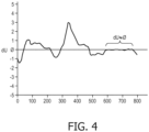
- Figure 4 shows an example of dU fluctuating over a cycle.
- dU tends to zero
- the window is identified for example by being: heuristically learnt by the processor; linked to characteristics of the pressure waveform; or a certain time window after another event in the waveform e.g. starting at a predetermined time (250ms) after event of dU max and lasting for a predetermined period (150ms) - note dU max can be reliably observed from pressure measurements of the waveform.
- the wave free period is identifiable using online analysis in real time disclosed as example or can be identified using offline analysis according to the invention.
- detecting minimised dU (wave free period) from pressure measurements can be carried out as follows:
- Another example for identifying the wave free period is to base its identification on characteristics of the pressure waveform. This is advantageous because identification is not tied to fixed time points.
- Another example for identifying the free wave period is:
- dU varies less than +/- 2 ⁇ 10 -4 from the zero crossing, where dU max is 3 ⁇ 10 -3 , where dU is 20% or less of dU max , preferably 10% or less, most preferably 5% or less.
- dU oscillates around the mean over the wave free period so its net contribution to separated pressures (i.e. P+) is minimised as the -ve contributions cancel the +ve contributions.
- the oscillations about the mean during the wave free period (the time window) in a cardiac environment are due to limitations in the measurement equipment, which will not detect small changes accurately.
- this advance provides a measure of the severity of a constriction using the measure of isolated pressure ratio.
- such devices or probes in the cardiac field include signal lines from the probe which terminate either in a transmitter for relaying the measurement signal to a processor or a processor itself. If there is a flow sensor and a pressure sensor, then two different measurement devices are in/on the same probe and there are also two signal lines required to take the signal from the two distinct measurement devices.
- the loss, in examples of the invention, of the flow sensor from the system is extremely beneficial as it reduces the complexity of the device, can improve handling of the probe and can reduce the number of signal lines necessary to take the measurement signal(s) away from the measurement devices.
- there is only one measurement device - that of pressure measurement and the need for a flow sensor in addition to one or more pressure sensors is obviated.
- a single pressure sensor wire can be more manoeuvrable than a wire with both pressure and flow sensors. Having a flow sensor in addition to the pressure sensor is sub-optimal for guide wire design.
- Pressure-only measurements are taken relative to the constriction. Multiple measurements can be taken in preference to one measurement.
- the probe 2 can be moved relative to the constriction, in which case, multiple measurements would be taken.
- the isolated pressure ratio using separated pressures is thus isolated forward pressure: P + distal P + proximal or isolated backward pressure, P ⁇ distal P ⁇ proximal
Landscapes
- Health & Medical Sciences (AREA)
- Life Sciences & Earth Sciences (AREA)
- Engineering & Computer Science (AREA)
- Physics & Mathematics (AREA)
- Cardiology (AREA)
- Public Health (AREA)
- Veterinary Medicine (AREA)
- Pathology (AREA)
- Biomedical Technology (AREA)
- Heart & Thoracic Surgery (AREA)
- Medical Informatics (AREA)
- Molecular Biology (AREA)
- Surgery (AREA)
- Animal Behavior & Ethology (AREA)
- General Health & Medical Sciences (AREA)
- Biophysics (AREA)
- Physiology (AREA)
- Vascular Medicine (AREA)
- Artificial Intelligence (AREA)
- Computer Vision & Pattern Recognition (AREA)
- Hematology (AREA)
- Signal Processing (AREA)
- Psychiatry (AREA)
- Oral & Maxillofacial Surgery (AREA)
- Dentistry (AREA)
- Mathematical Physics (AREA)
- Fuzzy Systems (AREA)
- Evolutionary Computation (AREA)
- Measuring Pulse, Heart Rate, Blood Pressure Or Blood Flow (AREA)
- Measuring Fluid Pressure (AREA)
- Measuring Volume Flow (AREA)
- Testing Of Devices, Machine Parts, Or Other Structures Thereof (AREA)
- Examining Or Testing Airtightness (AREA)
Description
- This invention relates to an apparatus and method of assessing a narrowing in a fluid filled tube.
- A fluid filled tube or vessel formed with a constriction or narrowing can be analyzed to measure the magnitude of the constriction or narrowing.
- An example of a fluid filled tube or vessel formed with a constriction or narrowing is a blood vessel having a stenosis. Assessment or measurement of the constriction can result in a useful parameter to gauge the extent of the constriction.
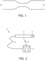
- A standard methodology for assessment of a constriction in a fluid filled tube such as a coronary stenosis is fractional flow reserve (FFR). This technique measures the drop in pressure at two points along a vessel; see
Figure 1 of the accompanying drawings, under conditions of maximal achievable hyperaemia in a coronary environment. The Pd measurement comes from a pressure sensor on the wire and the Pa measurement comes from the catheter. A comparison is then made by expressing the mean distal pressure (Pd), as a proportion of mean proximal pressure (Pa), wherein the values are mean Pa and Pd over the entire cardiac cycle, taken over at least one complete cardiac cycle (but usually an average of 3 or more beats):
- Distal pressure arises from resistance of the microcirculation, in addition to active compression of small microcirculatory vessels, which permeate the myocardium. When flow is measured simultaneously at different sites, it is possible to separate the pressure components arising from the distal myocardium (backward-originating pressure), from those arising from the proximal end (forward-originating pressure),


- P+ isolates forward originating pressure by removing the backward-originating component, and therefore negates the need for administration of vasoactive agents such as adenosine. Thus by comparing the ratio of P+ on either side of a stenosis it is possible to estimate stenosis severity without requiring maximal hyperaemia to be achieved. The isolated forward pressure ratio is expressed as:

- Whilst the forward pressure ratio offers a considerable step forward as administration of vasodilator compounds are not required, it requires flow velocity to be measured in addition to pressure. This requires considerable extra skill, additional hardware and added expense.
- It is an object of the invention to provide an apparatus and method of assessing a narrowing in a fluid filled tube being a blood vessel of a cyclic fluid flow system, in particular a cardiac environment which does not require a measurement of flow velocity, fluid flow rate, in addition to pressure measurement.
- One aspect of the present invention, which is defined in
claim 1, is a method of assessing a narrowing in a fluid filled tube being a blood vessel of a cyclic fluid flow system, in particular a cardiac environment comprising: receiving from a storage device previously taken measurements of blood pressure waveform during a cardiac cycle on either side of the narrowing; separating the pressure components into the backward-originating pressure component and the forward-originating pressure component; identifying from the pressure-only measurements a time window when the differential of flow velocity is minimal or absent; deriving the backward- and forward-originating pressure components from the pressure measurements for the time window using the pressure waveform alone, dispensing with the need for measurement of flow velocity, and deriving an isolated pressure ratio of pressures on either side of the narrowing by using the backward-originating and/or the forward-originating pressure components so as to provide an assessment of the severity of the narrowing. - Another aspect of the present invention, which is defined in claim 10, is an apparatus to assess a narrowing in a fluid filled tube being a blood vessel of a cyclic fluid flow system, in particular a cardiac environment, comprising: a storage device configured to store previously taken measurements of blood pressure waveform during a cardiac cycle on either side of the narrowing, a processor operable to separate the pressure components into the backward-originating pressure component and the forward-originating pressure component and configured to:
receive the blood pressure measurements from the storage device; identify from the pressure-only measurements a time window when the differential of flow velocity is minimal or absent; derive the backward- and forward-originating pressure components from the pressure measurements for the time window using the pressure waveform alone, dispensing with the need for measurement of flow velocity; use the backward- and/or forward-originating pressure components for the time window to calculate an isolated pressure ratio of pressures on either side of the narrowing so as to provide an assessment of the severity of the narrowing. -
US 2010/234698 A1 discloses an intravascular sensor delivery device for measuring blood pressure within a vascular structure or passage. The device may be used to measure fractional flow reserve (FFR) across a stenotic lesion in order to assess the severity of the lesion. The sensor delivery device has a distal sleeve configured to pass or slide over a standard medical guidewire. -
US 6354999 B1 discloses a method and devices for detection, localization and characterization of occlusions, aneurysms, wall characteristics and vascular bed. An artificial pressure or flow excitation signal (a single signal or more) is introduced into the blood vessel (or in other tubular flowing fluid conduits), then the pressure and or flow are measured and analyzed. - J. E. Davis et al. "Evidence of a dominant backward-propagating "suction" wave responsible for diastolic coronary filling in humans, attenuated in left ventricular hypertrophy", Circulation, vol. 113, no. 14, 1768-1778, DOI: 10.1161/CIRCULATIONAHA.105.603050" discloses how wave intensity analysis can be used to identify and quantify the pressure-velocity waves in the human coronary artery. The "suction" wave propagating backwards through the coronary tree during ventricular relaxation is the most important wave in the initiation of forward coronary blood flow. This suction wave is significantly reduced in subjects with left ventricular hypertrophy.
- In order that the present invention may be more readily understood, embodiments of the invention will now be described with reference to the accompanying drawings, in which:
-
FIGURE 1 is a schematic diagram of a tube formed with a constriction with proximal (Pa) and distal (Pd) pressure measurement sites; -
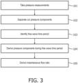
FIGURE 2 is a schematic not-to-scale diagram of an apparatus embodying the present invention; -
FIGURE 3 is a flow diagram illustrating a method embodying the present invention; -
FIGURE 4 shows an example of a free wave period in a cardiac environment, which free wave period is used in an apparatus and method embodying the present invention. - The invention is defined by the claims. This invention provides an apparatus and method of assessing a narrowing in a fluid filled tube by measuring the pressure in the tube and does not require a measurement of flow velocity, fluid flow rate, in addition to the pressure measurement.
- In a fluid flow system, the separated pressures are given as:


- The isolated forward pressure ratio using separated pressures is thus:


- Referring to
Figure 2 , anapparatus 1 embodying the invention comprises aprobe 2 such as an intra-arterial pressure wire (WaveWire or Combowire (Volcano Corp.) or Radi pressure wire (St Jude Medical) with a pressure measurement transducer 3 - i.e. a device measuring pressure (P), and aprocessor 4 to analyse and operate on the pressure measurements. Asignal line 5 relays the pressure measurement signal from thetransducer 3 to theprocessor 4. Thesignal line 5 is illustrated both as awired connection 5 and as a wireless connection 5' - either configuration is available. - The
processor 4 operates on the pressure measurements received from thetransducer 3 in accordance with a number of algorithms, which are discussed in greater detail below. Theapparatus 1 may be provided in the following configurations or combination of configurations, but these are not an exhaustive list of configurations: - i) a stand-alone device incorporating a probe with pressure measurement capacity in wired connection with a processor to provide on-device analysis;
- ii) a device incorporating a probe with pressure measurement capacity in wireless connection with a processor to provide analysis at the processor;
- iii) a stand-alone device incorporating a probe with pressure measurement capacity and a data storage device operable to record measurement data for real time or subsequent communication to a processor to provide analysis at the processor (real time and/or off-line); and
- iv) a device incorporating a probe with pressure measurement capacity in wireless connection with a data storage device operable to record measurement data for real time or subsequent communication to a processor to provide analysis at the processor (real time and/or off-line).
- In the cardiac environment where the
apparatus 1 is configured as part of haemodynamic equipment, the apparatus is configured using theprocessor 4 in the haemodynamic equipment, such as in McKesson equipment - Horizon Cardiology™, a cardiovascular information system (CVIS). Such configurations are particularly effective for the equipment processor to perform off-line analysis of the pressure data. - The apparatus 1 (and in particular the probe 2) can be used in combination with other haemodynamic equipment, medical imaging equipment and/or in-patient marker location equipment.
- In a cyclic fluid flow system, there are time windows in which the rate of change of the fluid flow velocity tends to zero - i.e. dU tends to zero. At these times, termed here "wave free periods", it is possible to separate the wave pressure in the fluid at a measurement site into forward and backward pressures using the pressure waveform alone. This negates the need for measurement of flow velocity.
- In a specific example of a cardiac cycle, at any point in the cardiac cycle dP+ is determined by dP + ρ c dU. dU is large during parts of the cardiac cycle when significant proportions of wave energy are present (i.e. during left ventricular contraction). However, there are times in the cardiac cycle when dU tends to zero. This can be a single moment or sample in time, or a multiple moments or samples in time. At such times, the dU term can be cancelled and dP+ or dP-, estimated using the dP term alone.
- In accordance with this example of the invention, pressure samples are taken at or over the wave free period when dU tends to zero. Precise adherence to pressure sampling at or over the wave free period is not essential but pressure sampling does need to take place when the influence of dU is minimised and preferably when tending to zero.
- At or over the wave free period when the influence of dU is minimised or negated entirely, the dU side is cancelled from the separated pressures so:
- dP+ is calculated as

- dP- is calculated as

- The apparatus and method provide for the separation of the wave pressure in the fluid at a measurement site into forward and backward pressures using the pressure waveform alone dispensing with the need for any measurement of flow velocity. This advance allows use of technically simplified equipment which does not need to measure fluid flow velocity.
- In the apparatus and method embodying the invention, the pressure measurements are made at baseline during the free wave period and not during hyperaemia. This is contrary to the teaching of FFR measurement in combined flow rate and pressure measurement apparatus where measurements are specifically taken at hyperaemia. This is because examples of the invention extract the forward pressure component, rather than (as in conventional FFR) having to minimise the contribution of backward pressure from the measured pressure by administration of vasodilators. If measurements are made during vasodilator hyperaemia, then measurements will not be reliable as dU increases significantly at this time.
-
Figure 4 shows an example of dU fluctuating over a cycle. There is an identifiable window where dU tends to zero (marked at 580ms through to 770ms in this example). The window is identified for example by being: heuristically learnt by the processor; linked to characteristics of the pressure waveform; or a certain time window after another event in the waveform e.g. starting at a predetermined time (250ms) after event of dUmax and lasting for a predetermined period (150ms) - note dUmax can be reliably observed from pressure measurements of the waveform. The wave free period is identifiable using online analysis in real time disclosed as example or can be identified using offline analysis according to the invention. - For example, in a cardiac environment, detecting minimised dU (wave free period) from pressure measurements can be carried out as follows:
- identify peak pressure time (tPmax)
- identify end of pressure waveform time (tPend)
- sample pressure measurements from tPmax to tPend
- analyse pressure measurements from (tPmax+150ms) through to (tPend -50ms) = wave free period.
- Another example for identifying the wave free period is to base its identification on characteristics of the pressure waveform. This is advantageous because identification is not tied to fixed time points. In this specific example:
- calculate the isolated forward (or backward) pressure ratio;
- calculate standard deviation of isolated forward (or backward) pressure ratio
- select the time period (free wave period) after peak pressure time point where the standard deviation is in the lowest 5% and if no points are identified, select the time period where the standard deviation is in the lowest 10% and so on.
- The measurements are continuous within the identified free wave period and/or for a period of at least ~=100ms.
- Another example for identifying the free wave period is:
- identify the peak pressure time point;
- identify the end of the pressure waveform time point; and
- specifying the free wave period as a predetermined portion mid-window between these two time points. Preferably, the free wave period is identified as the mid 3/5 window between these two time points.
- In the cardiac environment, reliable measurements are taken in the window where dU varies less than +/- 2×10⁻⁴ from the zero crossing, where dUmax is 3× 10⁻³, where dU is 20% or less of dUmax, preferably 10% or less, most preferably 5% or less. dU oscillates around the mean over the wave free period so its net contribution to separated pressures (i.e. P+) is minimised as the -ve contributions cancel the +ve contributions. The oscillations about the mean during the wave free period (the time window) in a cardiac environment are due to limitations in the measurement equipment, which will not detect small changes accurately.
- Further this advance provides a measure of the severity of a constriction using the measure of isolated pressure ratio.
- Further this advance negates the need in the cardiac environment for the administration of potent vasodilators.
- There are particular needs in the cardiac environment for simplified equipment having the smallest possible footprint (or being the least invasive requiring the smallest possible entry site) so the provision of an isolated pressure ratio measurement device or probe which has only one measurement device mounted on or in the probe represents a significant technical advance in that field.
- Further, such devices or probes in the cardiac field include signal lines from the probe which terminate either in a transmitter for relaying the measurement signal to a processor or a processor itself. If there is a flow sensor and a pressure sensor, then two different measurement devices are in/on the same probe and there are also two signal lines required to take the signal from the two distinct measurement devices. The loss, in examples of the invention, of the flow sensor from the system is extremely beneficial as it reduces the complexity of the device, can improve handling of the probe and can reduce the number of signal lines necessary to take the measurement signal(s) away from the measurement devices. In the case of examples of the invention, there is only one measurement device - that of pressure measurement and the need for a flow sensor in addition to one or more pressure sensors is obviated. A single pressure sensor wire can be more manoeuvrable than a wire with both pressure and flow sensors. Having a flow sensor in addition to the pressure sensor is sub-optimal for guide wire design.
- Pressure-only measurements are taken relative to the constriction. Multiple measurements can be taken in preference to one measurement. The
probe 2 can be moved relative to the constriction, in which case, multiple measurements would be taken. - There is a further sophistication to the above described apparatus and method which concerns the identification of wave free periods - those times in the cyclic flow when dU tends to zero. A person skilled in the art is able to calculate and identify wave free periods - occurring as they do during periods of the cardiac cycle when wave activity is minimised or absent.
- For a given wave free period from time point tw0 to time point tw1:
with P+ (during any wave free period tw0 to tw1) as,


- The isolated pressure ratio using separated pressures is thus isolated forward pressure:


- Calculating the isolated pressure ratio using this technique over the wave free period gives a pressure-only assessment of the severity of the constriction, such as a stenosis. There is no need to provide flow velocity measurement equipment on the
probe 2 in addition to thepressure measurement transducer 3 and there is no need to process any flow velocity measurement. - When used in this specification and claims, the terms "comprises" and "comprising" and variations thereof mean that the specified features, steps or integers are included. The terms are not to be interpreted to exclude the presence of other features, steps or components.
- The features disclosed in the foregoing description, or the following claims, or the accompanying drawings, expressed in their specific forms or in terms of a means for performing the disclosed function, or a method or process for attaining the disclosed result, as appropriate, may, separately, or in any combination of such features, be utilized for realizing the invention in diverse forms thereof.
Claims (14)
- A computer-implemented method of assessing a narrowing in a fluid filled tube being a blood vessel of a cyclic fluid flow system, in particular a cardiac environment, comprising:receiving from a storage device previously taken (101) measurements of blood pressure (Pd,Pa) waveform during a cardiac cycle on either side of the narrowing;identifying (103) from the blood pressure measurements a time window when the differential of flow velocity (dU) is minimal or absent;deriving (104) the backward- and forward-originating pressure components from the pressure measurements for the time window using the pressure waveform alone, dispensing with the need for measurement of flow velocity, andderiving (105) an isolated pressure ratio of pressures on either side of the narrowing by using the backward-originating and/or the forward-originating pressure components so as to provide an assessment of the severity of the narrowing.
- The method of claim 1, wherein the time window is from time point tw0 to time point tw1 and the forward-originating pressure component (P+) is:


- The method of claim 2, wherein the pressure ratio is:


- The method of any of the preceding claims, wherein the time window is identified by analyzing a characteristic of the pressure waveform.
- The method of any of the preceding claims, wherein the time window is identified as starting at a predetermined time after an identifiable event and lasting for: a predetermined period after the event; or a predetermined period before or after a further event.
- The method of claim 5, wherein the identifiable event is a peak pressure event and the further event is an end of pressure waveform event.
- The method of any of the preceding claims, wherein the time window is a wave free period identified as the time period in which the standard deviation of isolated forward or backward pressure ratio after a peak pressure time point is below a predetermined percentage.
- The method of any of the claims 1 to 6, wherein the time window is a wave free period identified by:identifying a peak pressure time point;identifying the end of the pressure waveform time point; andspecifying the free wave period as a predetermined portion mid-window between the peak pressure time point and the end of the pressure wave.
- The method of claim 8, wherein the predetermined portion mid-window is a mid 3/5 window between the peak pressure time point and the end of the pressure wave.
- An apparatus (1) for assessing a narrowing in a fluid filled tube being a blood vessel of a cyclic fluid flow system, in particular a cardiac environment, comprising:a storage device configured to store previously taken (101) measurements of blood pressure (Pd,Pa) waveform during a cardiac cycle on either side of the narrowing,a processor (4) operable to separate the pressure components into the backward-originating pressure component (P-) and the forward-originating pressure component (P+) and configured to:receive the blood pressure measurements from the storage device;identify from the pressure-only measurements a time window when the differential of flow velocity (dU) is minimal or absent;derive the backward- and forward-originating pressure components from the pressure measurements for the time window using the pressure waveform alone, dispensing with the need for measurement of flow velocity;use the backward- and/or forward-originating pressure components for the time window to calculate an isolated pressure ratio of pressures on either side of the narrowing so as to provide an assessment of the severity of the narrowing.
- The apparatus of claim 10, wherein the time window is identified as starting at a predetermined time after an identifiable event and lasting for: a predetermined period after the event; or a predetermined period before or after a further event.
- The apparatus of claim 11, wherein the identifiable event is a peak pressure event and the further event is an end of the pressure wave.
- The apparatus of claim 10, wherein the time window is identified by:identifying a peak pressure time point;identifying the end of the pressure wave; andspecifying the time window as a predetermined portion mid-window between these two time points.
- The apparatus of claim 13, wherein the predetermined portion mid-window is a mid 3/5 window between the peak pressure time point and the end of the pressure wave.
Applications Claiming Priority (3)
| Application Number | Priority Date | Filing Date | Title |
|---|---|---|---|
| GBGB1100137.7A GB201100137D0 (en) | 2011-01-06 | 2011-01-06 | Apparatus and method of assessing a narrowing in a fluid tube |
| EP12700299.6A EP2661216B1 (en) | 2011-01-06 | 2012-01-06 | Apparatus and method of assessing a narrowing in a fluid filled tube |
| PCT/GB2012/050024 WO2012093266A1 (en) | 2011-01-06 | 2012-01-06 | Apparatus and method of assessing a narrowing in a fluid filled tube |
Related Parent Applications (1)
| Application Number | Title | Priority Date | Filing Date |
|---|---|---|---|
| EP12700299.6A Division EP2661216B1 (en) | 2011-01-06 | 2012-01-06 | Apparatus and method of assessing a narrowing in a fluid filled tube |
Publications (2)
| Publication Number | Publication Date |
|---|---|
| EP3505057A1 EP3505057A1 (en) | 2019-07-03 |
| EP3505057B1 true EP3505057B1 (en) | 2024-07-31 |
Family
ID=43663843
Family Applications (2)
| Application Number | Title | Priority Date | Filing Date |
|---|---|---|---|
| EP18206377.6A Active EP3505057B1 (en) | 2011-01-06 | 2012-01-06 | Apparatus and method of assessing a narrowing in a fluid filled tube |
| EP12700299.6A Active EP2661216B1 (en) | 2011-01-06 | 2012-01-06 | Apparatus and method of assessing a narrowing in a fluid filled tube |
Family Applications After (1)
| Application Number | Title | Priority Date | Filing Date |
|---|---|---|---|
| EP12700299.6A Active EP2661216B1 (en) | 2011-01-06 | 2012-01-06 | Apparatus and method of assessing a narrowing in a fluid filled tube |
Country Status (14)
| Country | Link |
|---|---|
| US (5) | US9026384B2 (en) |
| EP (2) | EP3505057B1 (en) |
| JP (2) | JP6165634B2 (en) |
| KR (1) | KR101572337B1 (en) |
| CN (1) | CN103796577B (en) |
| BR (1) | BR112013017430A2 (en) |
| CA (1) | CA2823811A1 (en) |
| CR (1) | CR20130379A (en) |
| ES (1) | ES2706731T3 (en) |
| GB (1) | GB201100137D0 (en) |
| IL (1) | IL227351A0 (en) |
| NZ (1) | NZ613147A (en) |
| RU (1) | RU2013136699A (en) |
| WO (1) | WO2012093266A1 (en) |
Families Citing this family (50)
| Publication number | Priority date | Publication date | Assignee | Title |
|---|---|---|---|---|
| GB201100137D0 (en) | 2011-01-06 | 2011-02-23 | Davies Helen C S | Apparatus and method of assessing a narrowing in a fluid tube |
| AU2012262258B2 (en) | 2011-05-31 | 2015-11-26 | Lightlab Imaging, Inc. | Multimodal imaging system, apparatus, and methods |
| US10648918B2 (en) | 2011-08-03 | 2020-05-12 | Lightlab Imaging, Inc. | Systems, methods and apparatus for determining a fractional flow reserve (FFR) based on the minimum lumen area (MLA) and the constant |
| US9339348B2 (en) | 2011-08-20 | 2016-05-17 | Imperial Colege of Science, Technology and Medicine | Devices, systems, and methods for assessing a vessel |
| WO2013028612A2 (en) | 2011-08-20 | 2013-02-28 | Volcano Corporation | Devices, systems, and methods for visually depicting a vessel and evaluating treatment options |
| SE537177C2 (en) * | 2011-10-28 | 2015-02-24 | St Jude Medical Systems Ab | Medical system for determining the Fractional Flow Reserve (FFR) value |
| WO2013109815A1 (en) | 2012-01-19 | 2013-07-25 | Volcano Corporation | Interface devices, systems, and methods for use with intravascular pressure monitoring devices |
| WO2014036477A1 (en) | 2012-08-31 | 2014-03-06 | Volcano Corporation | Pressure sensing intravascular devices with reduced drift and associated systems and methods |
| US10398386B2 (en) | 2012-09-12 | 2019-09-03 | Heartflow, Inc. | Systems and methods for estimating blood flow characteristics from vessel geometry and physiology |
| US10433740B2 (en) | 2012-09-12 | 2019-10-08 | Heartflow, Inc. | Systems and methods for estimating ischemia and blood flow characteristics from vessel geometry and physiology |
| EP2967370B1 (en) | 2013-03-15 | 2021-09-29 | Philips Image Guided Therapy Corporation | Interface devices, systems, and methods for use with intravascular pressure monitoring devices |
| US10835183B2 (en) | 2013-07-01 | 2020-11-17 | Zurich Medical Corporation | Apparatus and method for intravascular measurements |
| EP2996552B1 (en) | 2013-07-01 | 2024-09-04 | Zurich Medical Corporation | Apparatus and method for intravascular measurements |
| WO2015058060A1 (en) | 2013-10-18 | 2015-04-23 | Volcano Corporation | Devices, systems, and methods for assessing a vessel with optimized proximal and distal pressure measurements obtained without the use of a hyperemic agent |
| US10130269B2 (en) | 2013-11-14 | 2018-11-20 | Medtronic Vascular, Inc | Dual lumen catheter for providing a vascular pressure measurement |
| US9877660B2 (en) | 2013-11-14 | 2018-01-30 | Medtronic Vascular Galway | Systems and methods for determining fractional flow reserve without adenosine or other pharmalogical agent |
| US9913585B2 (en) | 2014-01-15 | 2018-03-13 | Medtronic Vascular, Inc. | Catheter for providing vascular pressure measurements |
| US9974443B2 (en) | 2014-02-20 | 2018-05-22 | Koninklijke Philips N.V. | Devices, systems, and methods and associated display screens for assessment of vessels |
| CN111938616A (en) | 2014-04-04 | 2020-11-17 | 圣犹达医疗系统公司 | Intravascular pressure and flow data diagnostic systems, devices, and methods |
| JP6586425B2 (en) | 2014-04-21 | 2019-10-02 | コーニンクレッカ フィリップス エヌ ヴェKoninklijke Philips N.V. | Intravascular device, system and method having separate sections with core elements engaged |
| US10973418B2 (en) | 2014-06-16 | 2021-04-13 | Medtronic Vascular, Inc. | Microcatheter sensor design for minimizing profile and impact of wire strain on sensor |
| US10201284B2 (en) | 2014-06-16 | 2019-02-12 | Medtronic Vascular Inc. | Pressure measuring catheter having reduced error from bending stresses |
| US11330989B2 (en) | 2014-06-16 | 2022-05-17 | Medtronic Vascular, Inc. | Microcatheter sensor design for mounting sensor to minimize induced strain |
| US10849511B2 (en) | 2014-07-14 | 2020-12-01 | Philips Image Guided Therapy Corporation | Devices, systems, and methods for assessment of vessels |
| WO2016008809A1 (en) | 2014-07-15 | 2016-01-21 | Koninklijke Philips N.V. | Devices, systems, and methods and associated display screens for assessment of vessels with multiple sensing components |
| WO2016038493A1 (en) | 2014-09-11 | 2016-03-17 | Koninklijke Philips N.V. | Bedside controller for assessment of vessels and associated devices, systems, and methods |
| US10080872B2 (en) | 2014-11-04 | 2018-09-25 | Abbott Cardiovascular Systems Inc. | System and method for FFR guidewire recovery |
| WO2016075601A1 (en) | 2014-11-14 | 2016-05-19 | Koninklijke Philips N.V. | Percutaneous coronary intervention (pci) planning interface with pressure data and vessel data and associated devices, systems, and methods |
| WO2016075590A1 (en) | 2014-11-14 | 2016-05-19 | Koninklijke Philips N.V. | Percutaneous coronary intervention (pci) planning interface and associated devices, systems, and methods |
| WO2016092398A1 (en) | 2014-12-08 | 2016-06-16 | Koninklijke Philips N.V. | Device and method to recommend diagnostic procedure based on co-registered angiographic image and physiological information measured by intravascular device |
| WO2016092403A1 (en) | 2014-12-08 | 2016-06-16 | Koninklijke Philips N.V. | Automated identification and classification of intravascular lesions |
| US10194812B2 (en) | 2014-12-12 | 2019-02-05 | Medtronic Vascular, Inc. | System and method of integrating a fractional flow reserve device with a conventional hemodynamic monitoring system |
| CN107920764B (en) * | 2015-07-17 | 2021-09-21 | 皇家飞利浦有限公司 | Device, system and method for evaluating a vessel |
| WO2017171802A1 (en) * | 2016-03-31 | 2017-10-05 | Edwards Lifesciences Corporation | Aortic stenosis screening |
| US11272850B2 (en) | 2016-08-09 | 2022-03-15 | Medtronic Vascular, Inc. | Catheter and method for calculating fractional flow reserve |
| US11330994B2 (en) | 2017-03-08 | 2022-05-17 | Medtronic Vascular, Inc. | Reduced profile FFR catheter |
| US10646122B2 (en) | 2017-04-28 | 2020-05-12 | Medtronic Vascular, Inc. | FFR catheter with covered distal pressure sensor and method of manufacture |
| EP3644846B1 (en) * | 2017-08-03 | 2022-10-19 | Boston Scientific Scimed, Inc. | Systems for assessing fractional flow reserve |
| US11235124B2 (en) | 2017-08-09 | 2022-02-01 | Medtronic Vascular, Inc. | Collapsible catheter and method for calculating fractional flow reserve |
| US11219741B2 (en) | 2017-08-09 | 2022-01-11 | Medtronic Vascular, Inc. | Collapsible catheter and method for calculating fractional flow reserve |
| US11311196B2 (en) | 2018-02-23 | 2022-04-26 | Boston Scientific Scimed, Inc. | Methods for assessing a vessel with sequential physiological measurements |
| WO2019183432A1 (en) | 2018-03-23 | 2019-09-26 | Boston Scientific Scimed, Inc. | Medical device with pressure sensor |
| WO2019195721A1 (en) | 2018-04-06 | 2019-10-10 | Boston Scientific Scimed, Inc. | Medical device with pressure sensor |
| CN112292073A (en) | 2018-04-18 | 2021-01-29 | 波士顿科学国际有限公司 | System for evaluating vessels with continuous physiological measurements |
| ES2915828T3 (en) | 2018-04-20 | 2022-06-27 | Acist Medical Sys Inc | Evaluation of a glass |
| US11395597B2 (en) * | 2018-06-26 | 2022-07-26 | General Electric Company | System and method for evaluating blood flow in a vessel |
| US11185244B2 (en) | 2018-08-13 | 2021-11-30 | Medtronic Vascular, Inc. | FFR catheter with suspended pressure sensor |
| EP3624056B1 (en) | 2018-09-13 | 2021-12-01 | Siemens Healthcare GmbH | Processing image frames of a sequence of cardiac images |
| EP4133999A4 (en) * | 2020-05-08 | 2023-08-16 | Insight Lifetech Co., Ltd. | System and method for tracking cardiac circulatory event by using blood pressure |
| US12087000B2 (en) | 2021-03-05 | 2024-09-10 | Boston Scientific Scimed, Inc. | Systems and methods for vascular image co-registration |
Family Cites Families (106)
| Publication number | Priority date | Publication date | Assignee | Title |
|---|---|---|---|---|
| IL77677A (en) | 1986-01-22 | 1990-04-29 | Daniel Goor | Method and apparatus for detecting mycardial ischemia |
| US6190355B1 (en) | 1992-01-10 | 2001-02-20 | Scimed Life Systems, Inc. | Heated perfusion balloon for reduction of restenosis |
| EP0778746B1 (en) | 1994-09-02 | 2006-01-11 | Volcano Therapeutics, Inc. | Ultra miniature pressure sensor and guidewire using the same |
| SE9600334D0 (en) | 1996-01-30 | 1996-01-30 | Radi Medical Systems | Combined flow, pressure and temperature sensor |
| US5775338A (en) | 1997-01-10 | 1998-07-07 | Scimed Life Systems, Inc. | Heated perfusion balloon for reduction of restenosis |
| US6296615B1 (en) | 1999-03-05 | 2001-10-02 | Data Sciences International, Inc. | Catheter with physiological sensor |
| WO1999034724A2 (en) * | 1998-01-12 | 1999-07-15 | Florence Medical Ltd. | Characterizing blood vessel using multi-point pressure measurements |
| JPH11211594A (en) | 1998-01-28 | 1999-08-06 | Mitsubishi Electric Corp | Semiconductor pressure sensor |
| US6193669B1 (en) | 1998-12-11 | 2001-02-27 | Florence Medical Ltd. | System and method for detecting, localizing, and characterizing occlusions, stent positioning, dissections and aneurysms in a vessel |
| AU3187900A (en) | 1999-03-09 | 2000-09-28 | Florence Medical Ltd. | A method and system for pressure based measurements of cfr and additional clinical hemodynamic parameters |
| US20030032886A1 (en) | 1999-03-09 | 2003-02-13 | Elhanan Dgany | System for determining coronary flow reserve (CFR) value for a stenosed blood vessel, CFR processor therefor, and method therefor |
| US6471656B1 (en) | 1999-06-25 | 2002-10-29 | Florence Medical Ltd | Method and system for pressure based measurements of CFR and additional clinical hemodynamic parameters |
| US6129674A (en) | 1999-03-26 | 2000-10-10 | Ramot Of Tel-Aviv University | Method for determining the degree of occulsion and elasticity in blood vessels and other conduits |
| US6409677B1 (en) | 1999-05-27 | 2002-06-25 | Radi Medical Systems Ab | Method for temperature compensation in a combined pressure and temperature sensor |
| JP2001010107A (en) | 1999-06-25 | 2001-01-16 | Asahi Optical Co Ltd | Multi-beam light source scanning device |
| WO2001013779A2 (en) | 1999-08-25 | 2001-03-01 | Florence Medical Ltd. | A method and system for stenosis identification, localization and characterization using pressure measurements |
| US6605053B1 (en) * | 1999-09-10 | 2003-08-12 | Percardia, Inc. | Conduit designs and related methods for optimal flow control |
| US6354999B1 (en) * | 2000-01-14 | 2002-03-12 | Florence Medical Ltd. | System and method for detecting, localizing, and characterizing occlusions and aneurysms in a vessel |
| US6565514B2 (en) | 2000-08-25 | 2003-05-20 | Radi Medical Systems Ab | Method and system for determining physiological variables |
| US6558334B2 (en) | 2000-10-19 | 2003-05-06 | Florence Medical Ltd. | Apparatus for diagnosing lesion severity, and method therefor |
| US20030191400A1 (en) | 2001-01-19 | 2003-10-09 | Florence Medical Ltd. | System for determining values of hemodynamic parameters for a lesioned blood vessel, processor therefor, and method therefor |
| US6800090B2 (en) | 2001-05-14 | 2004-10-05 | Cardiac Dimensions, Inc. | Mitral valve therapy device, system and method |
| US6585660B2 (en) | 2001-05-18 | 2003-07-01 | Jomed Inc. | Signal conditioning device for interfacing intravascular sensors having varying operational characteristics to a physiology monitor |
| EP1260175B8 (en) | 2001-05-23 | 2011-02-16 | St. Jude Medical Systems AB | Interactive measurement system |
| US7532920B1 (en) | 2001-05-31 | 2009-05-12 | Advanced Cardiovascular Systems, Inc. | Guidewire with optical fiber |
| US7329223B1 (en) | 2001-05-31 | 2008-02-12 | Abbott Cardiovascular Systems Inc. | Catheter with optical fiber sensor |
| US6697667B1 (en) | 2001-05-31 | 2004-02-24 | Advanced Cardiovascular Systems, Inc. | Apparatus and method for locating coronary sinus |
| US6716178B1 (en) | 2001-05-31 | 2004-04-06 | Advanced Cardiovascular Systems, Inc. | Apparatus and method for performing thermal and laser doppler velocimetry measurements |
| US6824562B2 (en) | 2002-05-08 | 2004-11-30 | Cardiac Dimensions, Inc. | Body lumen device anchor, device and assembly |
| US6976995B2 (en) | 2002-01-30 | 2005-12-20 | Cardiac Dimensions, Inc. | Fixed length anchor and pull mitral valve device and method |
| US6868736B2 (en) | 2002-02-22 | 2005-03-22 | Sentec Corporation | Ultra-miniature optical pressure sensing system |
| US6663570B2 (en) | 2002-02-27 | 2003-12-16 | Volcano Therapeutics, Inc. | Connector for interfacing intravascular sensors to a physiology monitor |
| CA2950492C (en) | 2002-05-08 | 2018-12-04 | Cardiac Dimensions Pty. Ltd. | Device and method for modifying the shape of a body organ |
| US7134994B2 (en) | 2002-05-20 | 2006-11-14 | Volcano Corporation | Multipurpose host system for invasive cardiovascular diagnostic measurement acquisition and display |
| US20070225614A1 (en) | 2004-05-26 | 2007-09-27 | Endothelix, Inc. | Method and apparatus for determining vascular health conditions |
| US20040102806A1 (en) * | 2002-11-27 | 2004-05-27 | Scimed Life Systems, Inc. | Intravascular filter monitoring |
| US7316708B2 (en) | 2002-12-05 | 2008-01-08 | Cardiac Dimensions, Inc. | Medical device delivery system |
| JP2006517117A (en) | 2003-01-16 | 2006-07-20 | ガリル メディカル リミテッド | Apparatus, system, and method for detecting, locating, and identifying plaque-induced stenosis of blood vessels |
| US7204798B2 (en) * | 2003-01-24 | 2007-04-17 | Proteus Biomedical, Inc. | Methods and systems for measuring cardiac parameters |
| WO2004068406A2 (en) | 2003-01-30 | 2004-08-12 | Chase Medical, L.P. | A method and system for image processing and contour assessment |
| US20040158321A1 (en) | 2003-02-12 | 2004-08-12 | Cardiac Dimensions, Inc. | Method of implanting a mitral valve therapy device |
| US20100152607A1 (en) | 2003-02-21 | 2010-06-17 | Kassab Ghassan S | Devices, systems, and methods for measuring parallel tissue conductance, luminal cross-sectional areas, fluid velocity, and/or determining plaque vulnerability using temperature |
| JP4559215B2 (en) * | 2003-05-14 | 2010-10-06 | ボルケーノ・コーポレイション | A multi-purpose host system for capturing and displaying invasive cardiovascular diagnostic measurements |
| US7887582B2 (en) | 2003-06-05 | 2011-02-15 | Cardiac Dimensions, Inc. | Device and method for modifying the shape of a body organ |
| US20050121734A1 (en) | 2003-11-07 | 2005-06-09 | Georgia Tech Research Corporation | Combination catheter devices, methods, and systems |
| US7794496B2 (en) | 2003-12-19 | 2010-09-14 | Cardiac Dimensions, Inc. | Tissue shaping device with integral connector and crimp |
| WO2005070299A1 (en) | 2004-01-16 | 2005-08-04 | The University Of Houston System | Methods and apparatus for medical imaging |
| JP2005291945A (en) * | 2004-03-31 | 2005-10-20 | Masaki Esashi | Sensor device |
| SE0402145D0 (en) | 2004-09-08 | 2004-09-08 | Radi Medical Systems | Pressure measurement system |
| US8277386B2 (en) | 2004-09-27 | 2012-10-02 | Volcano Corporation | Combination sensor guidewire and methods of use |
| US20070055151A1 (en) * | 2005-01-20 | 2007-03-08 | Shertukde Hemchandra M | Apparatus and methods for acoustic diagnosis |
| US7632304B2 (en) | 2005-09-07 | 2009-12-15 | Rbkpark Llc | Coronary stent |
| US7775988B2 (en) | 2005-09-30 | 2010-08-17 | Radi Medical Systems Ab | Method for determining the blood flow in a coronary artery |
| US8184367B2 (en) | 2006-02-15 | 2012-05-22 | University Of Central Florida Research Foundation | Dynamically focused optical instrument |
| US20070225606A1 (en) | 2006-03-22 | 2007-09-27 | Endothelix, Inc. | Method and apparatus for comprehensive assessment of vascular health |
| US20100081941A1 (en) | 2006-03-22 | 2010-04-01 | Endothelix, Inc. | Cardiovascular health station methods and apparatus |
| US20070255145A1 (en) | 2006-04-28 | 2007-11-01 | Radi Medical Systems Ab | Sensor and guide wire assembly |
| US20080027330A1 (en) | 2006-05-15 | 2008-01-31 | Endothelix, Inc. | Risk assessment method for acute cardiovascular events |
| US20090081120A1 (en) | 2006-09-01 | 2009-03-26 | Cv Therapeutics, Inc. | Methods and Compositions for Increasing Patient Tolerability During Myocardial Imaging Methods |
| RU2459626C2 (en) | 2006-09-01 | 2012-08-27 | Гайлид Сайэнсиз, Инк. | Methods and compositions improving patient's tolerance of myocardial visualisation technique |
| US10503872B2 (en) | 2006-09-29 | 2019-12-10 | Gearbox Llc | Computational systems for biomedical data |
| US10095836B2 (en) | 2006-09-29 | 2018-10-09 | Gearbox Llc | Computational systems for biomedical data |
| US7853626B2 (en) | 2006-09-29 | 2010-12-14 | The Invention Science Fund I, Llc | Computational systems for biomedical data |
| US8029447B2 (en) | 2006-10-10 | 2011-10-04 | Volcano Corporation | Multipurpose host system for invasive cardiovascular diagnostic measurement acquisition including an enhanced dynamically configured graphical display |
| US7415093B2 (en) | 2006-10-30 | 2008-08-19 | General Electric Company | Method and apparatus of CT cardiac diagnostic imaging using motion a priori information from 3D ultrasound and ECG gating |
| US20080139951A1 (en) | 2006-12-08 | 2008-06-12 | Cardiac Pacemakers, Inc. | Detection of Stenosis |
| US9629571B2 (en) | 2007-03-08 | 2017-04-25 | Sync-Rx, Ltd. | Co-use of endoluminal data and extraluminal imaging |
| US10716528B2 (en) | 2007-03-08 | 2020-07-21 | Sync-Rx, Ltd. | Automatic display of previously-acquired endoluminal images |
| US8553832B2 (en) | 2007-05-21 | 2013-10-08 | Siemens Aktiengesellschaft | Device for obtaining perfusion images |
| US7869864B2 (en) | 2007-07-09 | 2011-01-11 | Dynacardia, Inc. | Methods, systems and devices for detecting and diagnosing heart diseases and disorders |
| US8216151B2 (en) | 2007-09-25 | 2012-07-10 | Radi Medical Systems Ab | Pressure wire assembly |
| US9289137B2 (en) | 2007-09-28 | 2016-03-22 | Volcano Corporation | Intravascular pressure devices incorporating sensors manufactured using deep reactive ion etching |
| US20090234231A1 (en) | 2008-03-13 | 2009-09-17 | Knight Jon M | Imaging Catheter With Integrated Contrast Agent Injector |
| EP2296553B1 (en) | 2008-05-16 | 2018-09-26 | Volcano Corporation | Miniature forward-looking ultrasound imaging mechanism enabled by local shape memory alloy actuator |
| US8006594B2 (en) | 2008-08-11 | 2011-08-30 | Cardiac Dimensions, Inc. | Catheter cutting tool |
| AU2009291623B2 (en) | 2008-09-11 | 2015-02-19 | Acist Medical Systems, Inc. | Physiological sensor delivery device and method |
| CA2738167A1 (en) | 2008-09-22 | 2010-03-25 | Ghassan S. Kassab | Devices, systems, and methods for determining fractional flow reserve |
| US20100086483A1 (en) | 2008-09-29 | 2010-04-08 | Gilead Palo Alto, Inc. | Method of multidetector computed tomagraphy |
| US20100109104A1 (en) | 2008-10-30 | 2010-05-06 | Radi Medical Systems Ab | Pressure sensor and wire guide assembly |
| US9974509B2 (en) | 2008-11-18 | 2018-05-22 | Sync-Rx Ltd. | Image super enhancement |
| US8970578B2 (en) | 2008-12-19 | 2015-03-03 | Szilard Voros | System and method for lesion-specific coronary artery calcium quantification |
| CA2748541A1 (en) | 2008-12-30 | 2010-07-08 | Endothelix, Inc. | Cardiohealth methods and apparatus |
| GB0904435D0 (en) * | 2009-03-13 | 2009-04-29 | King David H | Haemodynamic data estimation |
| EP2408356B1 (en) * | 2009-03-17 | 2018-05-23 | Opsens Inc. | Eccentric pressure catheter with guidewire compatibility |
| US8388542B2 (en) | 2009-05-04 | 2013-03-05 | Siemens Medical Solutions Usa, Inc. | System for cardiac pathology detection and characterization |
| BR112012001042A2 (en) | 2009-07-14 | 2016-11-22 | Gen Hospital Corp | fluid flow measurement equipment and method within anatomical structure. |
| WO2011018468A1 (en) | 2009-08-10 | 2011-02-17 | P2-Science Aps | Utp for the diagnosis of stenoses and other conditions of restricted blood flow |
| ES2569605T3 (en) * | 2009-09-18 | 2016-05-11 | St. Jude Medical Coordination Center Bvba | Device to acquire physiological variables measured in a body |
| US9301699B2 (en) | 2009-09-18 | 2016-04-05 | St. Jude Medical Coordination Center Bvba | Device for acquiring physiological variables measured in a body |
| EP4386667A2 (en) | 2009-09-23 | 2024-06-19 | Light-Lab Imaging Inc. | Lumen morphology and vascular resistance measurements data collection systems, apparatus and methods |
| US20110137210A1 (en) | 2009-12-08 | 2011-06-09 | Johnson Marie A | Systems and methods for detecting cardiovascular disease |
| US8478384B2 (en) | 2010-01-19 | 2013-07-02 | Lightlab Imaging, Inc. | Intravascular optical coherence tomography system with pressure monitoring interface and accessories |
| US8706209B2 (en) | 2010-02-05 | 2014-04-22 | 3Dt Holdings, Llc | Devices, systems, and methods for measuring parallel tissue conductance, luminal cross-sectional areas, fluid velocity, and/or determining plaque vulnerability using temperature |
| US20110245693A1 (en) | 2010-03-30 | 2011-10-06 | Boston Scientific Scimed, Inc. | Intravascular pressure sensing |
| US20120101369A1 (en) | 2010-06-13 | 2012-04-26 | Angiometrix Corporation | Methods and systems for determining vascular bodily lumen information and guiding medical devices |
| JP2013534841A (en) | 2010-06-13 | 2013-09-09 | アンジオメトリックス コーポレーション | Diagnostic kit and method for measuring balloon dimensions in vivo |
| JP6099562B2 (en) | 2010-07-29 | 2017-03-22 | シンク−アールエックス,リミティド | Combined use of intraluminal data and extraluminal imaging |
| US8157742B2 (en) | 2010-08-12 | 2012-04-17 | Heartflow, Inc. | Method and system for patient-specific modeling of blood flow |
| US8315812B2 (en) | 2010-08-12 | 2012-11-20 | Heartflow, Inc. | Method and system for patient-specific modeling of blood flow |
| KR101690595B1 (en) | 2010-09-01 | 2016-12-28 | 엘지전자 주식회사 | Mobile Terminal And Method Of Managing Icon Using The Same |
| WO2012030882A1 (en) | 2010-09-03 | 2012-03-08 | Praxair Technology, Inc. | Valve guard |
| US8480598B2 (en) | 2010-09-14 | 2013-07-09 | Abbott Cardiovascular Systems Inc. | Guide wire with soldered multilayer coil member |
| US9119540B2 (en) | 2010-09-16 | 2015-09-01 | Siemens Aktiengesellschaft | Method and system for non-invasive assessment of coronary artery disease |
| US8559540B2 (en) | 2010-10-14 | 2013-10-15 | Nokia Corporation | Apparatus and method for trellis-based detection in a communication system |
| GB201100137D0 (en) * | 2011-01-06 | 2011-02-23 | Davies Helen C S | Apparatus and method of assessing a narrowing in a fluid tube |
| US9339348B2 (en) * | 2011-08-20 | 2016-05-17 | Imperial Colege of Science, Technology and Medicine | Devices, systems, and methods for assessing a vessel |
-
2011
- 2011-01-06 GB GBGB1100137.7A patent/GB201100137D0/en not_active Ceased
-
2012
- 2012-01-06 CN CN201280004879.6A patent/CN103796577B/en active Active
- 2012-01-06 CA CA2823811A patent/CA2823811A1/en not_active Abandoned
- 2012-01-06 WO PCT/GB2012/050024 patent/WO2012093266A1/en active Application Filing
- 2012-01-06 NZ NZ613147A patent/NZ613147A/en not_active IP Right Cessation
- 2012-01-06 US US13/345,495 patent/US9026384B2/en active Active
- 2012-01-06 RU RU2013136699/14A patent/RU2013136699A/en not_active Application Discontinuation
- 2012-01-06 EP EP18206377.6A patent/EP3505057B1/en active Active
- 2012-01-06 JP JP2013547911A patent/JP6165634B2/en active Active
- 2012-01-06 KR KR1020137020712A patent/KR101572337B1/en not_active IP Right Cessation
- 2012-01-06 BR BR112013017430A patent/BR112013017430A2/en not_active IP Right Cessation
- 2012-01-06 EP EP12700299.6A patent/EP2661216B1/en active Active
- 2012-01-06 ES ES12700299T patent/ES2706731T3/en active Active
-
2013
- 2013-07-04 IL IL227351A patent/IL227351A0/en active IP Right Grant
- 2013-08-05 CR CR20130379A patent/CR20130379A/en unknown
-
2015
- 2015-04-30 US US14/701,000 patent/US9775524B2/en active Active
-
2017
- 2017-06-21 JP JP2017121080A patent/JP6517271B2/en active Active
- 2017-10-03 US US15/723,182 patent/US10624544B2/en active Active
-
2020
- 2020-04-20 US US16/853,523 patent/US11389068B2/en active Active
-
2022
- 2022-07-18 US US17/867,155 patent/US20220354370A1/en active Pending
Also Published As
| Publication number | Publication date |
|---|---|
| WO2012093266A1 (en) | 2012-07-12 |
| KR101572337B1 (en) | 2015-11-26 |
| EP3505057A1 (en) | 2019-07-03 |
| US20220354370A1 (en) | 2022-11-10 |
| NZ613147A (en) | 2015-06-26 |
| KR20130135300A (en) | 2013-12-10 |
| BR112013017430A2 (en) | 2019-09-24 |
| CN103796577A (en) | 2014-05-14 |
| CN103796577B (en) | 2017-10-17 |
| GB201100137D0 (en) | 2011-02-23 |
| CA2823811A1 (en) | 2012-07-12 |
| JP6517271B2 (en) | 2019-05-22 |
| US11389068B2 (en) | 2022-07-19 |
| US20120278008A1 (en) | 2012-11-01 |
| CR20130379A (en) | 2014-05-16 |
| US9026384B2 (en) | 2015-05-05 |
| JP2017200591A (en) | 2017-11-09 |
| EP2661216B1 (en) | 2018-11-21 |
| JP6165634B2 (en) | 2017-07-19 |
| US20200260963A1 (en) | 2020-08-20 |
| JP2014504923A (en) | 2014-02-27 |
| US20150230714A1 (en) | 2015-08-20 |
| US10624544B2 (en) | 2020-04-21 |
| US9775524B2 (en) | 2017-10-03 |
| ES2706731T3 (en) | 2019-04-01 |
| RU2013136699A (en) | 2015-02-20 |
| US20180160914A1 (en) | 2018-06-14 |
| IL227351A0 (en) | 2013-09-30 |
| EP2661216A1 (en) | 2013-11-13 |
Similar Documents
| Publication | Publication Date | Title |
|---|---|---|
| EP3505057B1 (en) | Apparatus and method of assessing a narrowing in a fluid filled tube | |
| US20200260964A1 (en) | Systems and methods for diagnosing coronary microvascular disease | |
| CN102481103B (en) | System and method of measuring changes in arterial volume of a limb segment | |
| EP2087836B1 (en) | Apparatus and method for determining a physiological parameter | |
| CN105326486A (en) | Method and system for calculating blood vessel pressure difference and fractional flow reserve | |
| EP0238170A2 (en) | Method and apparatus for detecting myocardial ischemia | |
| JP2001504362A (en) | Non-destructive blood pressure measurement device without pressurized zone | |
| JP2014511114A (en) | Apparatus and method for delineating features of a stenosis in a fluid filled tube | |
| EP3922173A1 (en) | Systems and methods for obtaining a pulse wave velocity measurement | |
| CN107174197B (en) | Monitoring equipment and waveform display method and device thereof | |
| EP4185188B1 (en) | Method and device for determining a coronary microvascular resistance score | |
| EP3484346B1 (en) | Apparatus, system and method for feedback on quality of property measurement in a vessel | |
| EP3613339A1 (en) | Renal denervation preparation | |
| US20150051463A1 (en) | Oximetry Signal, Pulse-Pressure Correlator | |
| WO1992015240A1 (en) | Determining the instantaneous shear stress on the wall of a blood vessel |
Legal Events
| Date | Code | Title | Description |
|---|---|---|---|
| PUAI | Public reference made under article 153(3) epc to a published international application that has entered the european phase |
Free format text: ORIGINAL CODE: 0009012 |
|
| STAA | Information on the status of an ep patent application or granted ep patent |
Free format text: STATUS: THE APPLICATION HAS BEEN PUBLISHED |
|
| AC | Divisional application: reference to earlier application |
Ref document number: 2661216 Country of ref document: EP Kind code of ref document: P |
|
| AK | Designated contracting states |
Kind code of ref document: A1 Designated state(s): AL AT BE BG CH CY CZ DE DK EE ES FI FR GB GR HR HU IE IS IT LI LT LU LV MC MK MT NL NO PL PT RO RS SE SI SK SM TR |
|
| STAA | Information on the status of an ep patent application or granted ep patent |
Free format text: STATUS: REQUEST FOR EXAMINATION WAS MADE |
|
| 17P | Request for examination filed |
Effective date: 20200103 |
|
| RBV | Designated contracting states (corrected) |
Designated state(s): AL AT BE BG CH CY CZ DE DK EE ES FI FR GB GR HR HU IE IS IT LI LT LU LV MC MK MT NL NO PL PT RO RS SE SI SK SM TR |
|
| STAA | Information on the status of an ep patent application or granted ep patent |
Free format text: STATUS: EXAMINATION IS IN PROGRESS |
|
| 17Q | First examination report despatched |
Effective date: 20220317 |
|
| GRAP | Despatch of communication of intention to grant a patent |
Free format text: ORIGINAL CODE: EPIDOSNIGR1 |
|
| STAA | Information on the status of an ep patent application or granted ep patent |
Free format text: STATUS: GRANT OF PATENT IS INTENDED |
|
| INTG | Intention to grant announced |
Effective date: 20240226 |
|
| GRAS | Grant fee paid |
Free format text: ORIGINAL CODE: EPIDOSNIGR3 |
|
| GRAA | (expected) grant |
Free format text: ORIGINAL CODE: 0009210 |
|
| STAA | Information on the status of an ep patent application or granted ep patent |
Free format text: STATUS: THE PATENT HAS BEEN GRANTED |
|
| AC | Divisional application: reference to earlier application |
Ref document number: 2661216 Country of ref document: EP Kind code of ref document: P |
|
| AK | Designated contracting states |
Kind code of ref document: B1 Designated state(s): AL AT BE BG CH CY CZ DE DK EE ES FI FR GB GR HR HU IE IS IT LI LT LU LV MC MK MT NL NO PL PT RO RS SE SI SK SM TR |
|
| REG | Reference to a national code |
Ref country code: CH Ref legal event code: EP Ref country code: GB Ref legal event code: FG4D |
|
| REG | Reference to a national code |
Ref country code: DE Ref legal event code: R096 Ref document number: 602012080978 Country of ref document: DE |
|
| REG | Reference to a national code |
Ref country code: IE Ref legal event code: FG4D |
|
| REG | Reference to a national code |
Ref country code: DE Ref legal event code: R081 Ref document number: 602012080978 Country of ref document: DE Owner name: MEDSOLVE PTE LTD., SG Free format text: FORMER OWNER: MEDSOLVE LTD., LONDON, GB |