EP3504415B1 - Gasbetriebene brennkraftmaschine und verfahren zu deren betrieb - Google Patents
Gasbetriebene brennkraftmaschine und verfahren zu deren betrieb Download PDFInfo
- Publication number
- EP3504415B1 EP3504415B1 EP17755515.8A EP17755515A EP3504415B1 EP 3504415 B1 EP3504415 B1 EP 3504415B1 EP 17755515 A EP17755515 A EP 17755515A EP 3504415 B1 EP3504415 B1 EP 3504415B1
- Authority
- EP
- European Patent Office
- Prior art keywords
- gas
- gas quantity
- combustion
- dynamic load
- injecting
- Prior art date
- Legal status (The legal status is an assumption and is not a legal conclusion. Google has not performed a legal analysis and makes no representation as to the accuracy of the status listed.)
- Active
Links
- 238000002485 combustion reaction Methods 0.000 title claims description 54
- 238000000034 method Methods 0.000 title claims description 30
- 238000002347 injection Methods 0.000 claims description 33
- 239000007924 injection Substances 0.000 claims description 33
- 239000000203 mixture Substances 0.000 claims description 30
- 239000000446 fuel Substances 0.000 claims description 27
- 230000006835 compression Effects 0.000 claims description 18
- 238000007906 compression Methods 0.000 claims description 18
- MWUXSHHQAYIFBG-UHFFFAOYSA-N nitrogen oxide Inorganic materials O=[N] MWUXSHHQAYIFBG-UHFFFAOYSA-N 0.000 claims description 13
- 230000009467 reduction Effects 0.000 claims description 8
- 230000015572 biosynthetic process Effects 0.000 claims description 4
- 230000007423 decrease Effects 0.000 claims description 4
- 229960003753 nitric oxide Drugs 0.000 claims 1
- 239000007789 gas Substances 0.000 description 95
- 238000006722 reduction reaction Methods 0.000 description 7
- 230000001052 transient effect Effects 0.000 description 4
- 238000005259 measurement Methods 0.000 description 3
- 238000010531 catalytic reduction reaction Methods 0.000 description 2
- 230000009977 dual effect Effects 0.000 description 2
- 239000007788 liquid Substances 0.000 description 2
- 239000002699 waste material Substances 0.000 description 2
- 239000004215 Carbon black (E152) Substances 0.000 description 1
- 235000019484 Rapeseed oil Nutrition 0.000 description 1
- 239000003225 biodiesel Substances 0.000 description 1
- 238000009841 combustion method Methods 0.000 description 1
- 238000010586 diagram Methods 0.000 description 1
- 230000000694 effects Effects 0.000 description 1
- 230000007613 environmental effect Effects 0.000 description 1
- 229930195733 hydrocarbon Natural products 0.000 description 1
- 150000002430 hydrocarbons Chemical class 0.000 description 1
- 230000001105 regulatory effect Effects 0.000 description 1
Images

Classifications
-
- F—MECHANICAL ENGINEERING; LIGHTING; HEATING; WEAPONS; BLASTING
- F02—COMBUSTION ENGINES; HOT-GAS OR COMBUSTION-PRODUCT ENGINE PLANTS
- F02D—CONTROLLING COMBUSTION ENGINES
- F02D41/00—Electrical control of supply of combustible mixture or its constituents
- F02D41/0025—Controlling engines characterised by use of non-liquid fuels, pluralities of fuels, or non-fuel substances added to the combustible mixtures
- F02D41/0027—Controlling engines characterised by use of non-liquid fuels, pluralities of fuels, or non-fuel substances added to the combustible mixtures the fuel being gaseous
-
- F—MECHANICAL ENGINEERING; LIGHTING; HEATING; WEAPONS; BLASTING
- F02—COMBUSTION ENGINES; HOT-GAS OR COMBUSTION-PRODUCT ENGINE PLANTS
- F02D—CONTROLLING COMBUSTION ENGINES
- F02D19/00—Controlling engines characterised by their use of non-liquid fuels, pluralities of fuels, or non-fuel substances added to the combustible mixtures
- F02D19/02—Controlling engines characterised by their use of non-liquid fuels, pluralities of fuels, or non-fuel substances added to the combustible mixtures peculiar to engines working with gaseous fuels
- F02D19/021—Control of components of the fuel supply system
- F02D19/023—Control of components of the fuel supply system to adjust the fuel mass or volume flow
- F02D19/024—Control of components of the fuel supply system to adjust the fuel mass or volume flow by controlling fuel injectors
-
- F—MECHANICAL ENGINEERING; LIGHTING; HEATING; WEAPONS; BLASTING
- F02—COMBUSTION ENGINES; HOT-GAS OR COMBUSTION-PRODUCT ENGINE PLANTS
- F02D—CONTROLLING COMBUSTION ENGINES
- F02D19/00—Controlling engines characterised by their use of non-liquid fuels, pluralities of fuels, or non-fuel substances added to the combustible mixtures
- F02D19/06—Controlling engines characterised by their use of non-liquid fuels, pluralities of fuels, or non-fuel substances added to the combustible mixtures peculiar to engines working with pluralities of fuels, e.g. alternatively with light and heavy fuel oil, other than engines indifferent to the fuel consumed
- F02D19/08—Controlling engines characterised by their use of non-liquid fuels, pluralities of fuels, or non-fuel substances added to the combustible mixtures peculiar to engines working with pluralities of fuels, e.g. alternatively with light and heavy fuel oil, other than engines indifferent to the fuel consumed simultaneously using pluralities of fuels
- F02D19/10—Controlling engines characterised by their use of non-liquid fuels, pluralities of fuels, or non-fuel substances added to the combustible mixtures peculiar to engines working with pluralities of fuels, e.g. alternatively with light and heavy fuel oil, other than engines indifferent to the fuel consumed simultaneously using pluralities of fuels peculiar to compression-ignition engines in which the main fuel is gaseous
-
- F—MECHANICAL ENGINEERING; LIGHTING; HEATING; WEAPONS; BLASTING
- F02—COMBUSTION ENGINES; HOT-GAS OR COMBUSTION-PRODUCT ENGINE PLANTS
- F02D—CONTROLLING COMBUSTION ENGINES
- F02D41/00—Electrical control of supply of combustible mixture or its constituents
- F02D41/30—Controlling fuel injection
- F02D41/3011—Controlling fuel injection according to or using specific or several modes of combustion
- F02D41/3017—Controlling fuel injection according to or using specific or several modes of combustion characterised by the mode(s) being used
- F02D41/3035—Controlling fuel injection according to or using specific or several modes of combustion characterised by the mode(s) being used a mode being the premixed charge compression-ignition mode
- F02D41/3041—Controlling fuel injection according to or using specific or several modes of combustion characterised by the mode(s) being used a mode being the premixed charge compression-ignition mode with means for triggering compression ignition, e.g. spark plug
-
- F—MECHANICAL ENGINEERING; LIGHTING; HEATING; WEAPONS; BLASTING
- F02—COMBUSTION ENGINES; HOT-GAS OR COMBUSTION-PRODUCT ENGINE PLANTS
- F02D—CONTROLLING COMBUSTION ENGINES
- F02D41/00—Electrical control of supply of combustible mixture or its constituents
- F02D41/30—Controlling fuel injection
- F02D41/38—Controlling fuel injection of the high pressure type
- F02D41/40—Controlling fuel injection of the high pressure type with means for controlling injection timing or duration
- F02D41/402—Multiple injections
- F02D41/405—Multiple injections with post injections
-
- F—MECHANICAL ENGINEERING; LIGHTING; HEATING; WEAPONS; BLASTING
- F02—COMBUSTION ENGINES; HOT-GAS OR COMBUSTION-PRODUCT ENGINE PLANTS
- F02D—CONTROLLING COMBUSTION ENGINES
- F02D2250/00—Engine control related to specific problems or objectives
- F02D2250/36—Control for minimising NOx emissions
-
- Y—GENERAL TAGGING OF NEW TECHNOLOGICAL DEVELOPMENTS; GENERAL TAGGING OF CROSS-SECTIONAL TECHNOLOGIES SPANNING OVER SEVERAL SECTIONS OF THE IPC; TECHNICAL SUBJECTS COVERED BY FORMER USPC CROSS-REFERENCE ART COLLECTIONS [XRACs] AND DIGESTS
- Y02—TECHNOLOGIES OR APPLICATIONS FOR MITIGATION OR ADAPTATION AGAINST CLIMATE CHANGE
- Y02T—CLIMATE CHANGE MITIGATION TECHNOLOGIES RELATED TO TRANSPORTATION
- Y02T10/00—Road transport of goods or passengers
- Y02T10/10—Internal combustion engine [ICE] based vehicles
- Y02T10/30—Use of alternative fuels, e.g. biofuels
-
- Y—GENERAL TAGGING OF NEW TECHNOLOGICAL DEVELOPMENTS; GENERAL TAGGING OF CROSS-SECTIONAL TECHNOLOGIES SPANNING OVER SEVERAL SECTIONS OF THE IPC; TECHNICAL SUBJECTS COVERED BY FORMER USPC CROSS-REFERENCE ART COLLECTIONS [XRACs] AND DIGESTS
- Y02—TECHNOLOGIES OR APPLICATIONS FOR MITIGATION OR ADAPTATION AGAINST CLIMATE CHANGE
- Y02T—CLIMATE CHANGE MITIGATION TECHNOLOGIES RELATED TO TRANSPORTATION
- Y02T10/00—Road transport of goods or passengers
- Y02T10/10—Internal combustion engine [ICE] based vehicles
- Y02T10/40—Engine management systems
Definitions
- the present disclosure relates to a method for operating internal combustion engines, in particular internal combustion engines with direct injection of a gaseous fuel.
- a disadvantage of such internal combustion engines is a limited efficiency due to the relatively low compression ratio, which is necessary in order to avoid uncontrolled combustion by self-ignition of the gas-air mixture.
- Another disadvantage of such internal combustion engines is the limited dynamics when increasing loads.
- Combustion engines with direct injection of a gas into the combustion chamber are also known, the gas usually being injected at about 250 to 500 bar.
- This injection of the amount of gas into the combustion chamber typically begins around the end of the compression stroke near top dead center (TDC).
- TDC top dead center
- a small amount of pilot fuel, for example diesel, or spark ignition, for example a spark plug, is used to ignite this gas jet.
- the disadvantages of gas direct injection include high NO x emissions, since the gas introduced is primarily implemented in a mixture-controlled combustion.
- the significant energy expenditure that has to be applied to the compression of the gas to compress the gas can also be regarded as disadvantageous.
- engines with direct gas injection and diesel-typical compression levels are - depending on emissions legislation or environmental guidelines of the target markets - often equipped with measures to reduce this problem, such as exhaust gas recirculation or selective catalytic reduction (SCR).
- CA 2838120 A1 discloses a direct-injection, gas-powered engine that is ignited by auto-igniting a pilot fuel.
- US 2002/078918 A1 discloses another direct injection, gas powered engine.
- the object of the invention is achieved by a method according to claim 1 and an internal combustion engine according to claim 11.
- a method for low-nitrogen oxide combustion of a gaseous fuel in the combustion chamber of an internal combustion engine with internal mixture formation comprises injecting a first amount of gas during the intake process; the compression of the gas-air mixture; injecting a second quantity of gas beginning during or at the end of the compression, the first and the second quantity of gas being selected such that a predetermined value of the NO x emission is not exceeded; igniting the gas-air mixture; and the combustion of the total amount of gas from the first amount of gas and the second amount of gas, the first amount of gas being burned premixed and the second amount of gas being implemented predominantly in a mixture-controlled combustion.
- a corresponding internal combustion engine is also proposed.
- One advantage of the method is that the hybrid combustion concept - with a combination of premixed combustion and mixture-controlled combustion - enables operation with a high proportion of premixed combustion. This makes possible achieving low NO x emissions through a low proportion of mixture-controlled combustion of the injected gas stream, and increased control over the combustion process.
- the expression "a predetermined value of the NO x emission is not exceeded” means that this value can have different frames of reference.
- the value can refer, for example, to the total emission from a defined driving cycle, or to the average emission from a defined period of time, or on average by the amount of energy delivered (e.g. 3.5 g / kWh) or a value in real time or a mass concentration ( represent 1 g / Nm3).
- hybrid combustion process means that some of the fuel is converted to a premixed combustion and some is converted to a mixture controlled combustion.
- the gas injection into the cylinder is divided into at least two processes that are separated or spaced apart in time.
- the first gas injection takes place during the intake cycle, which enables an almost homogeneous mixing of this first gas quantity with air.
- a liquid pilot fuel is then typically injected near top dead center, followed by the injection of a second amount of gas.
- the first amount of gas burns in a premixed combustion of the largely or ideally homogeneous gas-air mixture formed.
- the second quantity of gas is converted in a mixture-controlled combustion.
- the respective injection or injection quantities of the first and second gas quantities and of the pilot fuel can be individually reduced, at least briefly, in some cases also to zero.
- the processes of injecting the first gas quantity and / or the second gas quantity can also each be further subdivided, that is to say divided into several individual phases.
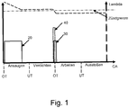
- Fig. 1 shows schematically the timing of a method according to embodiments of the invention. Shown is the injection of a first amount of gas 20 during the intake process, the air ratio of the gas-air mixture formed thereby being in the lean range above or far above the ignition limit.
- the gas-air mixture is compressed in the following compression. Towards the end of the compression, ie near top dead center (TDC), a second quantity of gas 30 is injected.
- the resulting gas-air mixture is ignited, preferably by injecting a pilot fuel 40 already at the start of the injection of the second gas quantity 30.
- the compressed gas-air mixture is burned, the first gas quantity 20 being burned premixed, and the second gas quantity is predominantly implemented in a mixture-controlled combustion
- the first and the second amount of gas are selected in accordance with exemplary embodiments so that a predetermined value of the NO x emission is not exceeded. This affects both the ratio of the two gas quantities to each other and their absolute values.
- the characteristic diagram of the injection system 100 is typically designed in such a way that the first and second injection quantities are dosed for at least some of the load cases and speeds so that a NO x target value is maintained.
- the map is typically determined during development on the basis of test measurements of the NO x emission.
- the respective emission value can be the basis for the metering of the injection quantities in real time.
- a given test cycle can be a stipulation in the time average (or in total) of a certain NO x level. For example, a relatively higher emission value in certain load cases can be compensated for or overcompensated by an emission in other load cases that is significantly below the target value.
- low-NO x operation can be realized in this way without additional constructive measures for NO x reduction, such as Exhaust gas recirculation or selective catalytic reduction would be required.
- the low emission level is also achieved by the compression ratio of typically about 9: 1 to about 14: 1, which is in the lower range for a self-igniting internal combustion engine.
- the disclosed concept also has an emission-minimizing effect with higher compression ratios, and accordingly higher compression engines are also considered to be covered by the present disclosure.
- the first gas quantity 20 and the second gas quantity 30 are varied as a function of the load. This concerns the absolute amounts and in particular also the ratio of the two gas amounts to one another. For example, the percentage of the second gas quantity (of the total gas quantity per cycle) can be reduced towards lower loads. This reduction in the case of partial load or low load can be carried out to such an extent that the second quantity of gas 30 is completely eliminated, that is to say reduced to zero.
- the ignition typically occurs by injection of the pilot fuel 40, as in FIG Fig. 1 shown near top dead center. Since the total amount of gas to be converted then only consists of the first injected amount of gas 20, it burns all the injected gas in premixed combustion, i.e. with low nitrogen oxide formation. In this case, only the pilot fuel 40 burns in a mixture-controlled combustion.
- the second gas quantity 30 is increased and the first gas quantity 20 is reduced.
- the first amount of gas can optionally be reduced to zero at short notice. Since the second quantity of gas burns due to the mixture-controlled combustion typically under lower total hydrocarbon (THC) emissions than the premixed combustion of the first quantity of gas 20, the THC emission during load changes can be minimized in this way.
- the first gas quantity 20 in particular can be reduced in the short term. This reduction can optionally take place to zero, so that only the second gas quantity 30 contributes to the combustion.
- the control of the first gas quantity 20 and / or the second gas quantity 30 will take place under the boundary condition of not exceeding a predetermined value of the THC emission.
- a regulating device can be provided, by means of which the amount of air entering the cylinder can be influenced.
- the regulator is either directly in the air path or influences it. It can be implemented in different ways, for example as a throttle valve, throttle valve, as a variable valve train (VVT), as a waste gate, or as a variable turbine geometry supercharger (VTG).
- VVT variable valve train
- VGT variable turbine geometry supercharger
- the independent regulation of the air quantity serves for dynamic power adjustment, in particular with a simultaneous increase in the first gas quantity 20.
- the pilot fuel 40 mentioned is typically injected at the start of the injection of the second gas quantity 30.
- the gas-air mixture is then ignited as a result of the self-ignition of the pilot fuel 40.
- the pilot fuel is usually diesel, but can also include other liquid fuels such as biodiesel, rapeseed oil, etc.
- the pilot fuel 40 can be injected earlier, namely early, during the compression. This is preferably done at a time corresponding to approximately 50 degrees before TDC to approximately 90 degrees before TDC.
- the ignition of the gas-air mixture can also take place by using spark ignition instead of by pilot fuel 40, in particular by a spark plug.
- FIG. 2 An internal combustion engine 60 is shown schematically, which is suitable for carrying out a method according to exemplary embodiments.
- This typically has a compression ratio between about 9: 1 and about 14: 1. It can be operated as a naturally aspirated engine or as a supercharged engine, in particular with an exhaust gas turbocharger (not shown).
- the engine has an injector 50 according to exemplary embodiments. This serves to inject the first gas quantity 20 or the second gas quantity 30 and the pilot fuel 40 into the cylinder 78 or the combustion chamber 77.
- the injector 50 can be designed in various ways.
- the gas and pilot fuel supplies can be provided in a single injector housing.
- Such an injector is used, for example, in the DE102014014452 (B4 ) disclosed.
- the injectors for gas and pilot fuel typically diesel, each being provided as separate injection or injection devices in the cylinder head 70, and versions in which several injectors for gas are used.
- the control element 80 already described above is shown in FIG Fig. 2 designed as a non-limiting example as a throttle valve.
- the control element 80 can generally be implemented in different ways in exemplary embodiments, for example as a throttle valve, as a variable valve train (VVT), as a waste gate, or as a variable turbine geometry supercharger (VTG).
- VVT variable valve train
- VVTG variable turbine geometry supercharger
- a division of the gas quantity into a first and a second gas quantity can typically influence the emissions both in stationary and in transient operation.
- increasing the second quantity of gas typically leads to an increase in NOx emissions and at the same time to a decrease in THC emissions.
- the division into a first and a second amount of gas according to exemplary embodiments thus allows regulation in fixed and / or also in transient operation to predetermined values of the NOx emissions and the THC emissions.
- the injection of the first and second gas quantities can thus be designed in accordance with exemplary embodiments in such a way that predetermined values of the NOx emissions and / or the THC emissions are maintained at any time, that is to say as real-time values, or also averaged over time, for example in a predetermined test -Motor cycle or the average of a continuous measurement over a predetermined period (for example 30 minutes) ..
- different division of the gas quantity into a first gas quantity and a second gas quantity in transient operation compared to stationary operation can also be used to set different, defined values for the NOx emissions and the THC emissions.
- a higher value for NOx emissions and a lower value for THC emissions can be specified than in stationary operation.
- This is achieved by proportionately increasing the second quantity of gas while simultaneously reducing the first quantity of gas.
- this proportionate increase in the second gas quantity with a proportionate reduction in the first gas quantity allows better dynamics in the case of load increases and load reductions.
- the ratio of the NOx emission and the THC emission in transient operation can be shifted for a short time, alternatively if the second gas quantity is increased towards higher NOx emissions and lower THC emissions conversely with a proportional reduction in the second quantity of gas towards lower NOx emissions and higher THC emissions.
- the gas quantity is divided into a first gas quantity and a second gas quantity according to the dynamic load change requirement while observing the specified values of the NOx emissions and the THC emissions, either temporarily in real time or on the average of a test engine cycle or on average continuous measurement over a given period of time (e.g. 30 minutes).
- the lower pressure level required when injecting the first quantity of gas during the intake, or the significantly lower mass fraction of the second quantity of gas, results in significant energy savings in comparison to direct-injection gas-powered engines, which contributes to an increase in the overall efficiency.
Landscapes
- Engineering & Computer Science (AREA)
- Chemical & Material Sciences (AREA)
- Combustion & Propulsion (AREA)
- Mechanical Engineering (AREA)
- General Engineering & Computer Science (AREA)
- Oil, Petroleum & Natural Gas (AREA)
- Output Control And Ontrol Of Special Type Engine (AREA)
- Electrical Control Of Air Or Fuel Supplied To Internal-Combustion Engine (AREA)
Description
- Die vorliegende Offenbarung betrifft ein Verfahren zum Betrieb von Brennkraftmaschinen, dabei insbesondere Verbrennungsmotoren mit Direkteindüsung eines gasförmigen Brennstoffs.
- Es ist bekannt, Verbrennungsmotoren, insbesondere Gasmotoren, mit äußerer Gemischbildung zu betreiben und das Gas-Luft-Gemisch durch Fremdzündung zu zünden. Auch bekannt sind sogenannte Dual Fuel Verbrennungsmotoren bei denen das Gas-Luft-Gemisch durch eine kleine Menge eines Pilot-Brennstoffs, zum Beispiel Diesel, gezündet wird. Solche Dual Fuel Verbrennungsmotoren können auch im reinen Dieselbetrieb betrieben werden.
- Nachteilig an solchen Verbrennungsmotoren ist eine begrenzte Effizienz aufgrund des relativ tiefen Verdichtungsverhältnisses, welches erforderlich ist, um ein unkontrolliertes Verbrennen durch Selbstzündung des Gas-Luft-Gemischs zu vermeiden. Ein weiterer Nachteil solcher Verbrennungsmotoren besteht in der eingeschränkten Dynamik bei Lasterhöhungen.
- Auch bekannt sind Verbrennungsmotoren mit direkter Eindüsung eines Gases in den Brennraum, wobei das Gas üblicherweise mit etwa 250 bis 500 bar eingedüst wird. Diese Eindüsung der Gasmenge in den Brennraum beginnt typischerweise etwa zum Ende des Kompressionstaktes nahe dem oberen Totpunkt (OT). Eine kleine Menge eines Pilot-Brennstoffs, zum Beispiel Diesel, oder eine Fremdzündung, zum Beispiel eine Zündkerze, wird eingesetzt, diesen Gasstrahl zu zünden.
- Verbrennungsmotoren mit Gas-Direkteindüsung weisen üblicherweise einen hohen thermischen Wirkungsgrad auf, der aus dem hohen Verdichtungsverhältnis resultiert. Dieses führt auch zu einem fast identischen Wirkungsgrad im reinen Dieselbetrieb. Bei dynamischen Vorgängen, im Zweistoff-Betrieb und bei reinem Dieselbetrieb ist das Verhalten vergleichbar zu dem reiner Dieselmotoren mit Direkteinspritzung.
- Zu den Nachteilen der Gas-Direkteindüsung gehören hohe NOx-Emissionen, da das eingebrachte Gas vor allem in einer mischungskontrollierten Verbrennung umgesetzt wird. Als nachteilig kann ferner der signifikante Energieaufwand angesehen werden, der zur Kompression des Gases auf den Eindüsungs-Druck aufgebracht werden muss. Wegen der prinzipbedingt hohen NOx-Emissionswerte werden Motoren mit Gas-Direkteindüsung und dieseltypischem Verdichtungsniveau daher häufig - je nach Emissionsgesetzgebung oder Umweltrichtlinien der Zielmärkte - mit Maßnahmen zur Minderung dieser Problematik ausgestattet, etwa einer Abgasrückführung oder selektiver katalytischer Reduktion (SCR).
-
CA 2838120 A1 offenbart einen direkteinspritzenden, gasbetriebenen Motor, der mittels Selbstzündung eines Pilot-Brennstoffs gezündet wird. -
US 2002/078918 A1 offenbart einen anderen direkteinspritzenden, gasbetriebenen Motor. - Vor dem Hintergrund des Standes der Technik besteht Bedarf nach Verbrennungsmotoren mit Gas-Direkteindüsung und Verfahren zu deren Betrieb, die verbesserte Eigenschaften, insbesondere eine verbesserte Emissions-Charakteristik aufweisen.
- Die Aufgabe der Erfindung wird gelöst durch ein Verfahren gemäß Anspruch 1 und einen Verbrennungsmotor gemäß Anspruch 11.
- In einem ersten Aspekt der Erfindung wird ein Verfahren zur stickoxid-armen Verbrennung eines gasförmigen Brennstoffs im Brennraum eines Verbrennungsmotors mit innerer Gemischbildung bereitgestellt. Das Verfahren umfasst das Eindüsen einer ersten Gasmenge während des Ansaugvorgangs; die Kompression des Gas-Luft-Gemischs; das Eindüsen einer zweiten Gasmenge beginnend während oder zum Ende der Kompression, wobei die erste und die zweite Gasmenge so gewählt werden, dass ein vorgegebener Wert der NOx-Emission nicht überschritten wird; das Zünden des Gas-Luft-Gemisches; und das Verbrennen der Gesamt-Gasmenge aus erster Gasmenge und zweiter Gasmenge, wobei die erste Gasmenge vorgemischt verbrannt wird, und die zweite Gasmenge vorwiegend in einer mischungskontrollierten Verbrennung umgesetzt wird. Zudem wird ein entsprechender Verbrennungsmotor vorgeschlagen.
- Ein Vorteil des Verfahrens besteht darin, dass das hybride Verbrennungskonzept - mit einer Kombination aus vorgemischter Verbrennung und mischungskontrollierter Verbrennung - einen Betrieb mit einem hohen Anteil an vorgemischter Verbrennung ermöglicht. Dies ermöglicht die Erzielung niedriger NOx-Emissionen durch einen geringen Anteil an mischungskontrollierter Verbrennung des eingedüsten Gasstroms, sowie eine erhöhte Kontrolle über den Verbrennungsprozess.
- Weitere Merkmale und Vorteile der vorliegenden Erfindung werden in der folgenden ausführlichen Beschreibung von bevorzugten Ausführungsformen des Systems vorgestellt.
- Weitere Merkmale und Vorteile der vorliegenden Erfindung werden für den Fachmann anhand der ausführlichen Beschreibung in Verbindung mit den angehängten Figuren ersichtlich. Dabei zeigen:
-
Fig. 1 zeigt ein Eindüsungsschema gemäß einem Verfahren nach Ausführungsformen der Erfindung; -
Fig. 2 zeigt einen Verbrennungsmotor zum Ausführen eines Verfahrens gemäß Ausführungsformen. - Auch wenn bevorzugte Ausführungsformen beschrieben werden, ist der Schutzbereich der Erfindung nicht auf dargestellten Ausführungsformen beschränkt, sondern umfasst auch für den Fachmann naheliegende Ausführungsformen im Rahmen der beigefügten Ansprüche.
- So wie er in dieser Offenbarung verwendet wird, bedeutet der Ausdruck: "ein vorgegebener Wert der NOx-Emission nicht überschritten wird", dass dieser Wert verschiedene Bezugsrahmen haben kann. Der Wert kann sich etwa auf die aufsummierte Emission aus einem definierten Fahrzyklus beziehen, oder auf die gemittelte Emission aus einer definierten Zeitspanne, oder im Mittel per abgegebener Energiemenge (z.B. 3,5 g/kWh) oder auch einen Wert in Echtzeit oder eine Massenkonzentration (z.B. 1 g/Nm3) darstellen.
- Grundsätzlich betreffen Ausführungsformen der Erfindung ein Verfahren zum Betrieb von Verbrennungsmotoren mit Gas-Direkteindüsung, wobei ein hybrides Verbrennungsverfahren zur Anwendung kommt. Gemäß der hierin verwendeten Bedeutung bezieht sich "hybrides Verbrennungsverfahren" darauf, dass ein Teil des Brennstoffs in einer vorgemischten Verbrennung und ein Teil in einer mischungskontrollierten Verbrennung umgesetzt wird.
- Grundsätzlich wird dazu, gemäß Ausführungsbeispielen der Erfindung, die Gas-Eindüsung in den Zylinder in mindestens zwei zeitlich voneinander getrennte bzw. beabstandete Vorgänge aufgeteilt. Die erste Gaseindüsung geschieht während des Einlass-Taktes, wodurch eine nahezu homogene Durchmischung dieser ersten Gasmenge mit Luft ermöglicht wird. Nahe dem oberen Totpunkt wird dann typischerweise ein flüssiger Pilot-Brennstoff eingespritzt, gefolgt von der Eindüsung einer zweiten Gasmenge. Die erste Gasmenge verbrennt in einer vorgemischten Verbrennung des gebildeten weitgehend bzw. idealerweise homogenen Gas-Luft-Gemischs. Die zweite Gasmenge wird dagegen in einer mischungskontrollierten Verbrennung umgesetzt. Da eine mischungskontrollierte Verbrennung grundsätzlich mit signifikant höheren NOx-Emissionen als eine vorgemischte Verbrennung bei den hier zur Anwendung kommenden Luftzahlen verbunden ist, ist der Stickoxid-Ausstoß des Motors deutlich reduziert im Vergleich zum reinen Direkteindüsungs-Betrieb, dies umso stärker, je größer die vorgemischt verbrennende erste Gasmenge im Verhältnis zur zweiten Gasmenge gewählt bzw. eingestellt wird.
- In einigen Ausführungsbeispielen, die im Folgenden noch genauer ausgeführt werden, können zumindest kurzfristig die jeweiligen Eindüs- oder Einspritzmengen der ersten und zweiten Gasmenge sowie des Pilot-Brennstoffs individuell reduziert werden, in einigen Fällen auch bis auf null reduziert werden. Auch können generell die Vorgänge des Eindüsens der ersten Gasmenge und/oder der zweiten Gasmenge jeweils weiter unterteilt, das heißt in mehreren Einzelphasen aufgeteilt vorgenommen werden.
-
Fig. 1 zeigt schematisch den zeitlichen Ablauf eines Verfahrens gemäß Ausführungsbeispielen der Erfindung. Gezeigt ist das Eindüsen einer ersten Gasmenge 20 während des Ansaugvorgangs, wobei die Luftzahl des dabei gebildeten Gas-Luft-Gemischs im mageren Bereich oberhalb oder weit oberhalb der Zündgrenze liegt. In der folgenden Kompression wird das Gas-Luft-Gemisch komprimiert. Gegen Ende der Kompression, d.h. nahe des oberen Totpunkts (OT), wird eine zweite Gasmenge 30 eingedüst. Das so entstandene Gas-Luft-Gemisch wird gezündet, vorzugsweise durch Einspritzung eines Pilot-Brennstoffs 40 bereits zu Beginn der Eindüsung der zweiten Gasmenge 30. Das komprimierte Gas-Luft-Gemisch wird verbrannt, wobei die erste Gasmenge 20 vorgemischt verbrannt wird, und die zweite Gasmenge vorwiegend in einer mischungskontrollierten Verbrennung umgesetzt wird Die erste und die zweite Gasmenge dabei werden gemäß Ausführungsbeispielen so gewählt, dass ein vorgegebener Wert der NOx-Emission nicht überschritten wird. Dies betrifft sowohl das Verhältnis der beiden Gasmengen zueinander als auch deren absolute Werte. - In Ausführungsbeispielen ist daher das Kennfeld des Einspritzsystems 100 typischerweise so ausgelegt, dass für zumindest einen Teil der Lastfälle und Drehzahlen die erste und zweite Einspritzmenge so dosiert sind, dass ein NOx-Zielwert eingehalten wird. Die Kennfeldfestlegung geschieht typischerweise während der Entwicklung anhand von Testmessungen der NOx -Emission. Dabei kann der jeweilige Emissionswert in Echtzeit Basis für die Zumessung der Eindüsmengen sein. In anderen Beispielen kann ein vorgegebener Testzyklus Maßgabe sein, in dessen zeitlichem Mittel (bzw. in Summe) ein bestimmtes NOx -Niveau eingehalten werden soll. So kann ein relativ höherer Emissionswert in bestimmten Lastfällen durch eine deutlich unter dem Zielwert liegende Emission in anderen Lastfällen kompensiert oder überkompensiert werden. Durch das weiter oben beschriebene, generell niedrige Niveau der NOx - Emission, das durch die hier beschriebenen Ausführungsformen möglich ist, lässt sich auf diese Weise ein NOx -armer Betrieb realisieren, ohne dass dazu weitere konstruktive Maßnahmen zur NOx-Reduzierung wie etwa Abgasrückführung oder Selektive katalytische Reduktion erforderlich wären. Das niedrige Emissionsniveau wird auch durch das für einen selbstzündenden Verbrennungsmotor eher im unteren Bereich liegende Verdichtungsverhältnis von typischerweise etwa 9:1 bis etwa 14:1 erzielt. Grundsätzlich wirkt das offenbarte Konzept jedoch auch mit höheren Verdichtungen emissions-minimierend, entsprechend höher verdichtete Motoren werden somit ebenfalls als unter die vorliegende Offenbarung fallend angesehen.
- Zur Lastregelung werden die erste Gasmenge 20 und die zweite Gasmenge 30 als Funktion der Last variiert. Dies betrifft die absoluten Mengen und insbesondere auch das Verhältnis der beiden Gasmengen zueinander. So kann etwa der prozentuale Anteil der zweiten Gasmenge (an der Gesamt-Gasmenge pro Zyklus) zu niedrigeren Lasten hin reduziert werden. Diese Reduzierung im Fall von Teillast bzw. niedriger Last kann soweit vorgenommen werden, dass die zweite Gasmenge 30 ganz wegfällt, also auf null reduziert wird. Die Zündung geschieht auch in diesem Fall typischerweise durch Einspritzung des Pilot-Brennstoffs 40, wie in
Fig. 1 dargestellt, nahe des oberen Totpunkts. Da die gesamte umzusetzende Gasmenge dann nur aus der ersten eingedüsten Gasmenge 20 besteht, verbrennt das gesamte eingedüste Gas in vorgemischter Verbrennung, das heißt unter geringen Stickoxid-Bildung. Lediglich der Pilot-Brennstoff 40 verbrennt in diesem Fall in einer mischungskontrollierten Verbrennung. - Im Fall von dynamischen Lasterhöhungen wird die zweite Gasmenge 30 erhöht und die erste Gasmenge 20 reduziert. Die erste Gasmenge kann dabei optional auch kurzfristig bis auf null abgesenkt werden. Da die zweite Gasmenge durch die mischungskontrollierte Verbrennung typischerweise unter geringeren Gesamt-Kohlenwasserstoff (total hydrocarbon - THC)-Emissionen als die vorgemischte Verbrennung der ersten Gasmenge 20 verbrennt, lässt sich auf diese Weise die THC-Emission bei Lastwechseln minimieren. Ebenso kann bei dynamischen Lastabsenkungen kurzfristig vor allem die erste Gasmenge 20 reduziert werden. Diese Reduzierung kann optional bis auf null erfolgen, so dass nur noch die zweite Gasmenge 30 zur Verbrennung beiträgt. Somit wird bei Lastwechseln die Steuerung der ersten Gasmenge 20 und/oder der zweiten Gasmenge 30 unter der Randbedingung erfolgen, einen vorgegebenen Wert der THC-Emission nicht zu überschreiten.
- In Ausführungsbeispielen kann ein Regelorgan vorgesehen sein, über das die in den Zylinder gelangende Luftmenge beeinflusst werden kann. Das Regelorgan befindet sich entweder direkt im Luftpfad oder beeinflusst ihn. Es kann auf unterschiedliche Weise realisiert sein, etwa als Drosselklappe, Drosselventil, als variabler Ventiltrieb (VVT), als Waste Gate, oder als Variable-Turbinengeometrie-Lader (VTG). Die unabhängige Regelung der Luftmenge dient der dynamischen Leistungsanpassung, insbesondere bei gleichzeitiger Erhöhung der ersten Gasmenge 20.
- Der in Bezug auf
Fig. 1 erwähnte Pilot-Brennstoff 40 wird typischerweise zu Beginn des Eindüsens der zweiten Gasmenge 30 eingespritzt. Das Zünden des Gas-Luft-Gemisches geschieht dann als Folge des Selbstzündens des Pilot-Brennstoffs 40. Der Pilot-Brennstoff ist üblicherweise Diesel, kann aber auch andere flüssige Brennstoffe wie Biodiesel, Rapsöl, etc. umfassen. - Wird, wie oben mit Bezug auf Teillast bzw. niedrige Lasten angeführt, bei niedrigen Lasten die zweite Gasmenge 30 weitgehend oder ganz bis auf null reduziert, so kann der Pilot-Brennstoff 40 bereits früher, nämlich noch früh während der Kompression eingespritzt werden. Bevorzugt geschieht dies zu einem Zeitpunkt entsprechend etwa 50 Grad vor OT bis etwa 90 Grad vor OT.
- In einigen Ausführungsbeispielen kann die Zündung des Gas-Luft-Gemisches statt durch den Pilot-Brennstoff 40 auch durch Anwenden einer Fremdzündung geschehen, insbesondere durch eine Zündkerze.
- In
Fig. 2 ist schematisch ein Verbrennungsmotor 60 dargestellt, der zur Ausführung eines Verfahrens gemäß Ausführungsbeispielen geeignet ist. Dieser weist typischerweise ein Verdichtungsverhältnis zwischen etwa 9:1 und etwa 14:1 auf. Er kann als Saugmotor oder als aufgeladener Motor betrieben werden, insbesondere mit einem Abgas-Turbolader (nicht gezeigt). Neben den Bestandteilen eines Viertaktmotors, nämlich Zylinder 78, Kolben 76, Einlassventil 72, Auslassventil 74, Brennraum 77 weist der Motor gemäß Ausführungsbeispielen einen Injektor 50 auf. Dieser dient zur Eindüsung der ersten Gasmenge 20 bzw. der zweiten Gasmenge 30, sowie des Pilot-Brennstoffs 40 in den Zylinder 78 bzw. den Brennraum 77. Der Injektor 50 kann auf verschiedene Weise ausgeführt sein. Wie dargestellt, können die Zuführungen für Gas und Pilot-Brennstoff in einem einzelnen Injektorgehäuse vorgesehen sein. Ein solcher Injektor wird beispielsweise in derDE102014014452 (B4 ) offenbart. Möglich sind auch baulich getrennte Ausführungen, wobei die Injektoren für Gas und Pilot-Brennstoff, typischerweise Diesel, jeweils als eigene Einspritz- bzw. Eindüsvorrichtungen im Zylinderkopf 70 bereitgestellt sind, sowie Ausführungen bei denen mehrere Injektoren für Gas zur Anwendung kommen. Grundsätzlich liegen in den meisten hier beschriebenen Ausführungsformen zwischen dem Ende des Eindüsens der ersten Gasmenge und dem Beginn des Eindüsens der zweiten Gasmenge ein Abstand von mindestens etwa 150 Grad Kurbelwinkel. Das bereits oben beschriebene Regelorgan 80 ist inFig. 2 als nicht-limitierendes Beispiel als Drosselklappe ausgeführt. Das Regelorgan 80 kann generell in Ausführungsbeispielen auf unterschiedliche Art und Weise realisiert sein, zum Beispiel als Drosselventil, als variabler Ventiltrieb (VVT), als Waste Gate, oder als Variable-Turbinengeometrie-Lader (VTG). - Die Vorteile der beschriebenen Ausführungsformen liegen vor allem in erheblich reduzierten NOx-Emissionswerten im Vergleich zu herkömmlichen direkt-eindüsenden gasbetriebenen Motoren. Im Vergleich zu herkömmlichen, im Magerbetrieb betriebenen Gasmotoren lassen sich mit einem derartigen "hybriden Verbrennungsverfahren" niedrige Stickoxidemissionen bei höheren thermischen Wirkungsgraden realisieren, ohne Abgasnachbehandlung. Zudem sind die THC-Emissionen geringer.
- Generell gilt, dass eine Aufteilung der Gasmenge in eine erste und eine zweite Gasmenge gemäß Ausführungsbeispielen typischerweise sowohl im stationären als auch im transienten Betrieb die Emissionen beeinflussen kann. Beispielsweise führt ein Erhöhen der zweiten Gasmenge typischerweise zu einem Anstieg der NOx-Emissionen und gleichzeitig zu sinkenden THC-Emissionen. Somit erlaubt die Aufteilung in eine erste und eine zweite Gasmenge gemäß Ausführungsbeispielen, im stationären und/oder auch im transienten Betrieb auf vorgegebene Werte der NOx-Emissionen und der THC-Emissionen zu regeln.
- Somit kann die Eindüsung der ersten und zweiten Gasmenge gemäß Ausführungsbeispielen so ausgelegt sein, dass vorgegebene Werte der NOx-Emissionen und/oder der THC-Emissionen jederzeit, das heißt als Echtzeit-Werte, oder auch zeitlich gemittelt eingehalten werden, etwa in einem vorgegebenen Test-Motorzyklus oder im Mittel einer kontinuierlichen Messung über einen vorgegebenen Zeitraum (von beispielsweise 30 Minuten)..
- Insbesondere kann durch unterschiedliche Aufteilung der Gasmenge in eine erste Gasmenge und eine zweite Gasmenge im transienten Betrieb gegenüber dem stationären Betrieb auch auf unterschiedliche, definierte Werte der NOx-Emissionen und der THC-Emissionen eingestellt werden. Beispielsweise kann bei dynamischen Lasterhöhungen ein höherer Wert für NOx-Emissionen und ein tieferer Wert für THC-Emissionen vorgegeben werden als im stationären Betrieb. Dies wird erreicht durch ein anteiliges Erhöhen der zweiten Gasmenge bei gleichzeitiger anteiliger Reduktion der ersten Gasmenge. Gleichzeitig erlaubt dieses anteilige Erhöhen der zweiten Gasmenge bei anteiliger Reduktion der ersten Gasmenge eine bessere Dynamik bei Lasterhöhungen und Lastabsenkungen. Durch eine Verschiebung des Verhältnisses der ersten Gasmenge und der zweiten Gasmenge kann also das Verhältnis der NOx-Emission und der THC-Emission im transienten Betrieb kurzfristig verschoben werden, bei Erhöhung der zweiten Gasmenge hin zu höheren NOx-Emissionen und geringeren THC-Emissionen, alternativ umgekehrt bei einer anteiligen Verringerung der zweiten Gasmenge hin zu niedrigeren NOx-Emissionen und höheren THC-Emissionen.
- Folglich erfolgt die Aufteilung der Gasmenge in eine erste Gasmenge und eine zweite Gasmenge entsprechend der dynamischen Anforderung bei Lastwechsel unter Einhaltung der vorgegebenen Werte der NOx-Emissionen und der THC-Emissionen, entweder kurzfristig in Echtzeit oder im Mittel eines Test-Motorzyklus oder im Mittel einer kontinuierlichen Messung über einen vorgegebenen Zeitraum (von beispielsweise 30 Minuten).
- Durch das geringere erforderliche Druckniveau beim Eindüsen der ersten Gasmenge während des Ansaugens, bzw. den deutlich geringeren Massenanteil der zweiten Gasmenge, ergibt sich eine signifikante Energieeinsparung im Vergleich zu direkteindüsenden gasbetriebenen Motoren, die zur Steigerung des Gesamtwirkungsgrades beiträgt.
Claims (11)
- Verfahren zur stickoxid-armen Verbrennung eines gasförmigen Brennstoffs im Brennraum eines Verbrennungsmotors (60) mit innerer Gemischbildung, umfassend:- Eindüsen einer ersten Gasmenge (20) während des Ansaugvorgangs;- Kompression des Gas-Luft-Gemischs;- Eindüsen einer zweiten Gasmenge (30) beginnend während oder zum Ende der Kompression, wobei die erste Gasmenge (20) und die zweite Gasmenge (30) so gewählt werden, dass ein vorgegebener Wert der NOx-Emission nicht überschritten wird;- Zünden des Gas-Luft-Gemisches,- Verbrennen der Gesamt-Gasmenge aus erster Gasmenge (20) und zweiter Gasmenge (30), wobei die erste Gasmenge vorgemischt verbrannt wird, und die zweite Gasmenge vorwiegend in einer mischungskontrollierten Verbrennung umgesetzt wird, wobeibei dynamischen Lasterhöhungen die zweite Gasmenge (30) erhöht wird und die erste Gasmenge (20) reduziert wird, und bei dynamischen Lastabsenkungen vor allem die erste Gasmenge (20) reduziert wird, und wobei
bei dynamischen Lasterhöhungen oder Lastabsenkungen eine Änderung der ersten Gasmenge (20) und/oder der zweiten Gasmenge (30) unter der Randbedingung erfolgt, einen vorgegebenen Wert der THC-Emission nicht zu überschreiten. - Verfahren nach Anspruch 1, wobei bei dynamischen Lasterhöhungen die zweite Gasmenge (30) erhöht wird und die erste Gasmenge (20) reduziert wird, bis auf null, und bei dynamischen Lastabsenkungen vor allem die erste Gasmenge (20) reduziert wird, bis auf null.
- Verfahren nach Anspruch 1 oder 2, wobei bei dynamischen Lasterhöhungen durch anteiliges Erhöhen der zweiten Gasmenge bei gleichzeitiger anteiliger Reduktion der ersten Gasmenge ein höherer Wert für NOx-Emissionen und ein niedrigerer Wert für THC-Emissionen eingeahlten wird als im stationären Betrieb.
- Verfahren nach einem der vorhergehenden Ansprüche, wobei ein Regelorgan (80) im Luftpfad vorgesehen ist, das die Luftmenge beeinflusst.
- Verfahren nach einem der vorhergehenden Ansprüche, wobei das Eindüsen der ersten Gasmenge (20) und/oder der zweiten Gasmenge (30) in mindestens zwei Einzelphasen aufgetrennt ist.
- Verfahren nach einem der vorhergehenden Ansprüche, wobei zu Beginn des Eindüsens der zweiten Gasmenge (30) ein Pilot-Brennstoff (40) eingespritzt wird, und wobei das Zünden des Gas-Luft-Gemisches durch Selbstzünden des Pilot-Brennstoffs (40) geschieht.
- Verfahren nach einem der Ansprüche 1 bis 5, wobei das Zünden des Gas-Luft-Gemischs durch Fremdzündung geschieht.
- Verfahren gemäß einem der vorhergehenden Ansprüche, wobei zwischen dem Ende des Eindüsens der ersten Gasmenge (20) und dem Beginn des Eindüsens der zweiten Gasmenge (30) ein Abstand von mindestens etwa 150 Grad Kurbelwinkel besteht.
- Verfahren nach einem der vorhergehenden Ansprüche, wobei der Verbrennungsmotor (60) ein Verdichtungsverhältnis zwischen etwa 9:1 und etwa 14:1 aufweist.
- Verfahren nach einem der Ansprüche 1 bis 6 oder 9, wobei bei niedrigen Lasten die zweite Gasmenge (30) bis auf null reduziert wird und der Pilot-Brennstoff (40) bereits früh während der Kompression eingespritzt wird, bevorzugt zu einem Zeitpunkt entsprechend 50 Grad vor OT bis 90 Grad vor OT.
- Ein Verbrennungsmotor (60), der eine Steuereinheit zur Anwendung eines Verfahrens gemäß einem der Ansprüche 1 bis 10 aufweist und zur Durchführung dieses Verfahrens ausgelegt ist.
Applications Claiming Priority (2)
| Application Number | Priority Date | Filing Date | Title |
|---|---|---|---|
| DE102016116039.3A DE102016116039A1 (de) | 2016-08-29 | 2016-08-29 | Gasbetriebene brennkraftmaschine und verfahren zu deren betrieb |
| PCT/EP2017/071235 WO2018041694A1 (de) | 2016-08-29 | 2017-08-23 | Gasbetriebene brennkraftmaschine und verfahren zu deren betrieb |
Publications (3)
| Publication Number | Publication Date |
|---|---|
| EP3504415A1 EP3504415A1 (de) | 2019-07-03 |
| EP3504415B1 true EP3504415B1 (de) | 2020-07-15 |
| EP3504415B8 EP3504415B8 (de) | 2020-08-26 |
Family
ID=59686965
Family Applications (1)
| Application Number | Title | Priority Date | Filing Date |
|---|---|---|---|
| EP17755515.8A Active EP3504415B8 (de) | 2016-08-29 | 2017-08-23 | Gasbetriebene brennkraftmaschine und verfahren zu deren betrieb |
Country Status (6)
| Country | Link |
|---|---|
| EP (1) | EP3504415B8 (de) |
| JP (1) | JP2019526748A (de) |
| KR (1) | KR102314994B1 (de) |
| CN (1) | CN109642506B (de) |
| DE (1) | DE102016116039A1 (de) |
| WO (1) | WO2018041694A1 (de) |
Family Cites Families (18)
| Publication number | Priority date | Publication date | Assignee | Title |
|---|---|---|---|---|
| US6675748B2 (en) * | 2000-02-11 | 2004-01-13 | Westport Research Inc. | Method and apparatus for fuel injection into an internal combustion engine |
| CA2398146C (en) * | 2000-02-11 | 2009-09-22 | Westport Research Inc. | Method and apparatus for gaseous fuel introduction and controlling combustion in an internal combustion engine |
| US6640773B2 (en) | 2000-12-26 | 2003-11-04 | Westport Research Inc. | Method and apparatus for gaseous fuel introduction and controlling combustion in an internal combustion engine |
| JP2003522877A (ja) * | 2000-02-11 | 2003-07-29 | ウエストポート リサーチ インク. | 内燃機関へ二重燃料噴射する方法および装置 |
| US6912992B2 (en) * | 2000-12-26 | 2005-07-05 | Cummins Westport Inc. | Method and apparatus for pilot fuel introduction and controlling combustion in gaseous-fuelled internal combustion engine |
| CA2406137C (en) * | 2002-10-02 | 2004-12-28 | Westport Research Inc. | Control method and apparatus for gaseous fuelled internal combustion engine |
| JP4472932B2 (ja) * | 2003-02-07 | 2010-06-02 | いすゞ自動車株式会社 | エンジンの燃焼制御装置 |
| CA2444163C (en) * | 2003-10-01 | 2007-01-09 | Westport Research Inc. | Method and apparatus for controlling combustion quality of a gaseous-fuelled internal combustion engine |
| US7044103B2 (en) * | 2004-08-16 | 2006-05-16 | Dresser, Inc. | Fuel quantity modulation in pilot ignited engines |
| JP5035088B2 (ja) * | 2007-08-06 | 2012-09-26 | 日産自動車株式会社 | エンジン |
| DE102008001606B4 (de) * | 2008-05-07 | 2019-11-21 | Robert Bosch Gmbh | Verfahren und Vorrichtung zum Betreiben einer Brennkraftmaschine |
| WO2013022630A1 (en) * | 2011-08-09 | 2013-02-14 | Clean Air Power, Inc. | Method and apparatus for controlling premixed combustion in a multimode engine |
| DE102012222368A1 (de) * | 2012-12-06 | 2014-06-12 | Schaeffler Technologies Gmbh & Co. Kg | Motorsteuergerät für einen Zündstrahlmotor und Verfahren zum Betrieb eines Zündstrahlmotors |
| US9399968B2 (en) * | 2013-09-05 | 2016-07-26 | Ford Global Technologies, Llc | Engine control for a liquid petroleum gas fueled engine |
| CA2838120C (en) | 2013-12-23 | 2015-06-23 | Westport Power Inc. | Method and apparatus for fuel injection and dynamic combustion control |
| DE102014014452B4 (de) | 2014-09-26 | 2016-07-14 | L'orange Gmbh | Dual-Fuel-Injektor, Verfahren zur Ausführung damit sowie Dual-Fuel-Kraftstoffeinspritzsystem |
| AT516289B1 (de) * | 2014-10-06 | 2016-07-15 | Ge Jenbacher Gmbh & Co Og | Verfahren zum Betreiben einer Selbstzündungs-Brennkraftmaschine |
| AT516543B1 (de) * | 2014-12-19 | 2021-01-15 | Innio Jenbacher Gmbh & Co Og | Verfahren zum Betreiben einer funkengezündeten Brennkraftmaschine |
-
2016
- 2016-08-29 DE DE102016116039.3A patent/DE102016116039A1/de not_active Withdrawn
-
2017
- 2017-08-23 KR KR1020197007741A patent/KR102314994B1/ko not_active Expired - Fee Related
- 2017-08-23 JP JP2019532178A patent/JP2019526748A/ja active Pending
- 2017-08-23 CN CN201780053421.2A patent/CN109642506B/zh not_active Expired - Fee Related
- 2017-08-23 WO PCT/EP2017/071235 patent/WO2018041694A1/de not_active Ceased
- 2017-08-23 EP EP17755515.8A patent/EP3504415B8/de active Active
Non-Patent Citations (1)
| Title |
|---|
| None * |
Also Published As
| Publication number | Publication date |
|---|---|
| CN109642506A (zh) | 2019-04-16 |
| JP2019526748A (ja) | 2019-09-19 |
| WO2018041694A1 (de) | 2018-03-08 |
| EP3504415B8 (de) | 2020-08-26 |
| KR102314994B1 (ko) | 2021-10-22 |
| KR20190039783A (ko) | 2019-04-15 |
| CN109642506B (zh) | 2022-02-22 |
| DE102016116039A1 (de) | 2018-03-01 |
| EP3504415A1 (de) | 2019-07-03 |
Similar Documents
| Publication | Publication Date | Title |
|---|---|---|
| DE102006007279B4 (de) | Kompressionsgezündeter Verbrennungsmotor und Betriebsverfahren | |
| DE60115926T2 (de) | Verfahren und vorrichtung für flüssiggasbrennstoffeinführung und steuerung der verbrennung einer brennkraftmaschine | |
| DE112005001363B4 (de) | Verfahren für den Mittellastbetrieb einer Selbstzündungsverbrennung | |
| DE10147529B4 (de) | Verfahren zum Betreiben einer mit selbstzündbarem Kraftstoff betriebenen Brennkraftmaschine | |
| DE112015000452B4 (de) | Steuerungsvorrichtung für eine Verbrennungskraftmaschine | |
| AT516289B1 (de) | Verfahren zum Betreiben einer Selbstzündungs-Brennkraftmaschine | |
| DE102017126611A1 (de) | Verbrennungszündvorrichtung für einen Verbrennungsmotor | |
| DE112015000460B4 (de) | Steuerungsvorrichtung für eine Verbrennungskraftmaschine | |
| WO2016155870A1 (de) | Brennkraftmaschine und verfahren zum betreiben einer brennkraftmaschine | |
| DE112011105137B4 (de) | Steuersystem für einen Mehrkraftstoff-Verbrennungszylinder | |
| DE112012004984T5 (de) | Motor, der mehrere Kraftstoffe nutzt, und zugehöriges Verfahren | |
| DE102005044544B4 (de) | Verfahren zum Betrieb einer fremdgezündeten 4-Takt-Brennkraftmaschine | |
| DE112016000983T5 (de) | Kraftstoffeinspritzungs-Steuerungsvorrichtung für einen Motor mit Direkteinspritzung | |
| DE102005004121A1 (de) | Steuerungseinrichtung für eine Direkteinspritzbrennkraftmaschine | |
| DE102010029728B4 (de) | Verfahren zur Steuerung einer Einspritzung von Kraftstoff in einen Verbrennungsmotor, Steuergerät zum Steuern einer Einspritzung in einem Verbrennungsmotor sowie Verfahren zum Auswählen eines Einspritzventils für ein Motorsystem | |
| WO2020249277A1 (de) | Verfahren zum betreiben einer brennkraftmaschine mit wasserstoff, wasserstoff-brennkraftmaschine und kraftfahrzeug | |
| DE10321794A1 (de) | Verfahren zum Betreiben einer Brennkraftmaschine | |
| EP3872330A1 (de) | Verfahren zum betreiben eines grossdieselmotors, sowie grossdieselmotor | |
| DE102019134628A1 (de) | Verfahren und Steuergerät zum Betreiben eines als Gasmotor oder Dual-Fuel-Motor ausgebildeten Motors | |
| DE112006001836T5 (de) | Mischmodussteuerverfahren und Motor, der dieses verwendet | |
| EP3504415B1 (de) | Gasbetriebene brennkraftmaschine und verfahren zu deren betrieb | |
| EP4045784B1 (de) | Verfahren zum betreiben einer brennkraftmaschine | |
| DE102006045422A1 (de) | Ottomotorisches Brennverfahren mit Magerbetrieb und Brennkraftmaschine für ein ottomotorisches Brennverfahren mit Magerbetrieb | |
| DE112018003690T5 (de) | Schmierölgesteuerte zündung in motoren | |
| DE102015221325B4 (de) | Verfahren zum Betreiben einer Brennkraftmaschine und Brennkraftmaschine |
Legal Events
| Date | Code | Title | Description |
|---|---|---|---|
| STAA | Information on the status of an ep patent application or granted ep patent |
Free format text: STATUS: UNKNOWN |
|
| STAA | Information on the status of an ep patent application or granted ep patent |
Free format text: STATUS: THE INTERNATIONAL PUBLICATION HAS BEEN MADE |
|
| PUAI | Public reference made under article 153(3) epc to a published international application that has entered the european phase |
Free format text: ORIGINAL CODE: 0009012 |
|
| STAA | Information on the status of an ep patent application or granted ep patent |
Free format text: STATUS: REQUEST FOR EXAMINATION WAS MADE |
|
| 17P | Request for examination filed |
Effective date: 20190315 |
|
| AK | Designated contracting states |
Kind code of ref document: A1 Designated state(s): AL AT BE BG CH CY CZ DE DK EE ES FI FR GB GR HR HU IE IS IT LI LT LU LV MC MK MT NL NO PL PT RO RS SE SI SK SM TR |
|
| GRAP | Despatch of communication of intention to grant a patent |
Free format text: ORIGINAL CODE: EPIDOSNIGR1 |
|
| STAA | Information on the status of an ep patent application or granted ep patent |
Free format text: STATUS: GRANT OF PATENT IS INTENDED |
|
| INTG | Intention to grant announced |
Effective date: 20200309 |
|
| GRAS | Grant fee paid |
Free format text: ORIGINAL CODE: EPIDOSNIGR3 |
|
| GRAA | (expected) grant |
Free format text: ORIGINAL CODE: 0009210 |
|
| STAA | Information on the status of an ep patent application or granted ep patent |
Free format text: STATUS: THE PATENT HAS BEEN GRANTED |
|
| AK | Designated contracting states |
Kind code of ref document: B1 Designated state(s): AL AT BE BG CH CY CZ DE DK EE ES FI FR GB GR HR HU IE IS IT LI LT LU LV MC MK MT NL NO PL PT RO RS SE SI SK SM TR |
|
| REG | Reference to a national code |
Ref country code: CH Ref legal event code: EP Ref country code: GB Ref legal event code: FG4D Free format text: NOT ENGLISH |
|
| REG | Reference to a national code |
Ref country code: DE Ref legal event code: R096 Ref document number: 502017006243 Country of ref document: DE |
|
| REG | Reference to a national code |
Ref country code: CH Ref legal event code: PK Free format text: BERICHTIGUNG B8 |
|
| REG | Reference to a national code |
Ref country code: IE Ref legal event code: FG4D Free format text: LANGUAGE OF EP DOCUMENT: GERMAN |
|
| REG | Reference to a national code |
Ref country code: AT Ref legal event code: REF Ref document number: 1291277 Country of ref document: AT Kind code of ref document: T Effective date: 20200815 |
|
| RAP2 | Party data changed (patent owner data changed or rights of a patent transferred) |
Owner name: ABB SCHWEIZ AG |
|
| RAP2 | Party data changed (patent owner data changed or rights of a patent transferred) |
Owner name: ABB SCHWEIZ AG |
|
| REG | Reference to a national code |
Ref country code: DE Ref legal event code: R081 Ref document number: 502017006243 Country of ref document: DE Owner name: TURBO SYSTEMS SWITZERLAND LTD., CH Free format text: FORMER OWNER: ABB TURBO SYSTEMS AG, BADEN, CH Ref country code: DE Ref legal event code: R082 Ref document number: 502017006243 Country of ref document: DE Representative=s name: ZIMMERMANN & PARTNER PATENTANWAELTE MBB, DE Ref country code: DE Ref legal event code: R081 Ref document number: 502017006243 Country of ref document: DE Owner name: ABB SCHWEIZ AG, CH Free format text: FORMER OWNER: ABB TURBO SYSTEMS AG, BADEN, CH |
|
| REG | Reference to a national code |
Ref country code: LT Ref legal event code: MG4D |
|
| REG | Reference to a national code |
Ref country code: NL Ref legal event code: MP Effective date: 20200715 |
|
| PG25 | Lapsed in a contracting state [announced via postgrant information from national office to epo] |
Ref country code: HR Free format text: LAPSE BECAUSE OF FAILURE TO SUBMIT A TRANSLATION OF THE DESCRIPTION OR TO PAY THE FEE WITHIN THE PRESCRIBED TIME-LIMIT Effective date: 20200715 Ref country code: BG Free format text: LAPSE BECAUSE OF FAILURE TO SUBMIT A TRANSLATION OF THE DESCRIPTION OR TO PAY THE FEE WITHIN THE PRESCRIBED TIME-LIMIT Effective date: 20201015 Ref country code: PT Free format text: LAPSE BECAUSE OF FAILURE TO SUBMIT A TRANSLATION OF THE DESCRIPTION OR TO PAY THE FEE WITHIN THE PRESCRIBED TIME-LIMIT Effective date: 20201116 Ref country code: SE Free format text: LAPSE BECAUSE OF FAILURE TO SUBMIT A TRANSLATION OF THE DESCRIPTION OR TO PAY THE FEE WITHIN THE PRESCRIBED TIME-LIMIT Effective date: 20200715 Ref country code: FI Free format text: LAPSE BECAUSE OF FAILURE TO SUBMIT A TRANSLATION OF THE DESCRIPTION OR TO PAY THE FEE WITHIN THE PRESCRIBED TIME-LIMIT Effective date: 20200715 Ref country code: NO Free format text: LAPSE BECAUSE OF FAILURE TO SUBMIT A TRANSLATION OF THE DESCRIPTION OR TO PAY THE FEE WITHIN THE PRESCRIBED TIME-LIMIT Effective date: 20201015 Ref country code: GR Free format text: LAPSE BECAUSE OF FAILURE TO SUBMIT A TRANSLATION OF THE DESCRIPTION OR TO PAY THE FEE WITHIN THE PRESCRIBED TIME-LIMIT Effective date: 20201016 Ref country code: LT Free format text: LAPSE BECAUSE OF FAILURE TO SUBMIT A TRANSLATION OF THE DESCRIPTION OR TO PAY THE FEE WITHIN THE PRESCRIBED TIME-LIMIT Effective date: 20200715 Ref country code: ES Free format text: LAPSE BECAUSE OF FAILURE TO SUBMIT A TRANSLATION OF THE DESCRIPTION OR TO PAY THE FEE WITHIN THE PRESCRIBED TIME-LIMIT Effective date: 20200715 |
|
| PG25 | Lapsed in a contracting state [announced via postgrant information from national office to epo] |
Ref country code: LV Free format text: LAPSE BECAUSE OF FAILURE TO SUBMIT A TRANSLATION OF THE DESCRIPTION OR TO PAY THE FEE WITHIN THE PRESCRIBED TIME-LIMIT Effective date: 20200715 Ref country code: PL Free format text: LAPSE BECAUSE OF FAILURE TO SUBMIT A TRANSLATION OF THE DESCRIPTION OR TO PAY THE FEE WITHIN THE PRESCRIBED TIME-LIMIT Effective date: 20200715 Ref country code: RS Free format text: LAPSE BECAUSE OF FAILURE TO SUBMIT A TRANSLATION OF THE DESCRIPTION OR TO PAY THE FEE WITHIN THE PRESCRIBED TIME-LIMIT Effective date: 20200715 Ref country code: IS Free format text: LAPSE BECAUSE OF FAILURE TO SUBMIT A TRANSLATION OF THE DESCRIPTION OR TO PAY THE FEE WITHIN THE PRESCRIBED TIME-LIMIT Effective date: 20201115 |
|
| PG25 | Lapsed in a contracting state [announced via postgrant information from national office to epo] |
Ref country code: NL Free format text: LAPSE BECAUSE OF FAILURE TO SUBMIT A TRANSLATION OF THE DESCRIPTION OR TO PAY THE FEE WITHIN THE PRESCRIBED TIME-LIMIT Effective date: 20200715 |
|
| REG | Reference to a national code |
Ref country code: CH Ref legal event code: PL |
|
| REG | Reference to a national code |
Ref country code: DE Ref legal event code: R097 Ref document number: 502017006243 Country of ref document: DE |
|
| PG25 | Lapsed in a contracting state [announced via postgrant information from national office to epo] |
Ref country code: LU Free format text: LAPSE BECAUSE OF NON-PAYMENT OF DUE FEES Effective date: 20200823 Ref country code: LI Free format text: LAPSE BECAUSE OF NON-PAYMENT OF DUE FEES Effective date: 20200831 Ref country code: DK Free format text: LAPSE BECAUSE OF FAILURE TO SUBMIT A TRANSLATION OF THE DESCRIPTION OR TO PAY THE FEE WITHIN THE PRESCRIBED TIME-LIMIT Effective date: 20200715 Ref country code: CZ Free format text: LAPSE BECAUSE OF FAILURE TO SUBMIT A TRANSLATION OF THE DESCRIPTION OR TO PAY THE FEE WITHIN THE PRESCRIBED TIME-LIMIT Effective date: 20200715 Ref country code: CH Free format text: LAPSE BECAUSE OF NON-PAYMENT OF DUE FEES Effective date: 20200831 Ref country code: RO Free format text: LAPSE BECAUSE OF FAILURE TO SUBMIT A TRANSLATION OF THE DESCRIPTION OR TO PAY THE FEE WITHIN THE PRESCRIBED TIME-LIMIT Effective date: 20200715 Ref country code: SM Free format text: LAPSE BECAUSE OF FAILURE TO SUBMIT A TRANSLATION OF THE DESCRIPTION OR TO PAY THE FEE WITHIN THE PRESCRIBED TIME-LIMIT Effective date: 20200715 Ref country code: EE Free format text: LAPSE BECAUSE OF FAILURE TO SUBMIT A TRANSLATION OF THE DESCRIPTION OR TO PAY THE FEE WITHIN THE PRESCRIBED TIME-LIMIT Effective date: 20200715 Ref country code: IT Free format text: LAPSE BECAUSE OF FAILURE TO SUBMIT A TRANSLATION OF THE DESCRIPTION OR TO PAY THE FEE WITHIN THE PRESCRIBED TIME-LIMIT Effective date: 20200715 |
|
| PLBE | No opposition filed within time limit |
Free format text: ORIGINAL CODE: 0009261 |
|
| STAA | Information on the status of an ep patent application or granted ep patent |
Free format text: STATUS: NO OPPOSITION FILED WITHIN TIME LIMIT |
|
| REG | Reference to a national code |
Ref country code: BE Ref legal event code: MM Effective date: 20200831 |
|
| PG25 | Lapsed in a contracting state [announced via postgrant information from national office to epo] |
Ref country code: AL Free format text: LAPSE BECAUSE OF FAILURE TO SUBMIT A TRANSLATION OF THE DESCRIPTION OR TO PAY THE FEE WITHIN THE PRESCRIBED TIME-LIMIT Effective date: 20200715 |
|
| 26N | No opposition filed |
Effective date: 20210416 |
|
| PG25 | Lapsed in a contracting state [announced via postgrant information from national office to epo] |
Ref country code: SK Free format text: LAPSE BECAUSE OF FAILURE TO SUBMIT A TRANSLATION OF THE DESCRIPTION OR TO PAY THE FEE WITHIN THE PRESCRIBED TIME-LIMIT Effective date: 20200715 |
|
| PG25 | Lapsed in a contracting state [announced via postgrant information from national office to epo] |
Ref country code: FR Free format text: LAPSE BECAUSE OF NON-PAYMENT OF DUE FEES Effective date: 20200915 |
|
| PG25 | Lapsed in a contracting state [announced via postgrant information from national office to epo] |
Ref country code: BE Free format text: LAPSE BECAUSE OF NON-PAYMENT OF DUE FEES Effective date: 20200831 Ref country code: IE Free format text: LAPSE BECAUSE OF NON-PAYMENT OF DUE FEES Effective date: 20200823 Ref country code: SI Free format text: LAPSE BECAUSE OF FAILURE TO SUBMIT A TRANSLATION OF THE DESCRIPTION OR TO PAY THE FEE WITHIN THE PRESCRIBED TIME-LIMIT Effective date: 20200715 |
|
| GBPC | Gb: european patent ceased through non-payment of renewal fee |
Effective date: 20210823 |
|
| PG25 | Lapsed in a contracting state [announced via postgrant information from national office to epo] |
Ref country code: TR Free format text: LAPSE BECAUSE OF FAILURE TO SUBMIT A TRANSLATION OF THE DESCRIPTION OR TO PAY THE FEE WITHIN THE PRESCRIBED TIME-LIMIT Effective date: 20200715 Ref country code: MT Free format text: LAPSE BECAUSE OF FAILURE TO SUBMIT A TRANSLATION OF THE DESCRIPTION OR TO PAY THE FEE WITHIN THE PRESCRIBED TIME-LIMIT Effective date: 20200715 Ref country code: CY Free format text: LAPSE BECAUSE OF FAILURE TO SUBMIT A TRANSLATION OF THE DESCRIPTION OR TO PAY THE FEE WITHIN THE PRESCRIBED TIME-LIMIT Effective date: 20200715 |
|
| PG25 | Lapsed in a contracting state [announced via postgrant information from national office to epo] |
Ref country code: MK Free format text: LAPSE BECAUSE OF FAILURE TO SUBMIT A TRANSLATION OF THE DESCRIPTION OR TO PAY THE FEE WITHIN THE PRESCRIBED TIME-LIMIT Effective date: 20200715 Ref country code: MC Free format text: LAPSE BECAUSE OF FAILURE TO SUBMIT A TRANSLATION OF THE DESCRIPTION OR TO PAY THE FEE WITHIN THE PRESCRIBED TIME-LIMIT Effective date: 20200715 |
|
| PG25 | Lapsed in a contracting state [announced via postgrant information from national office to epo] |
Ref country code: GB Free format text: LAPSE BECAUSE OF NON-PAYMENT OF DUE FEES Effective date: 20210823 |
|
| REG | Reference to a national code |
Ref country code: DE Ref legal event code: R081 Ref document number: 502017006243 Country of ref document: DE Owner name: TURBO SYSTEMS SWITZERLAND LTD., CH Free format text: FORMER OWNER: ABB SCHWEIZ AG, BADEN, CH |
|
| PGFP | Annual fee paid to national office [announced via postgrant information from national office to epo] |
Ref country code: DE Payment date: 20220819 Year of fee payment: 6 Ref country code: AT Payment date: 20220822 Year of fee payment: 6 |
|
| REG | Reference to a national code |
Ref country code: AT Ref legal event code: PC Ref document number: 1291277 Country of ref document: AT Kind code of ref document: T Owner name: TURBO SYSTEMS SWITZERLAND LTD, CH Effective date: 20230320 |
|
| REG | Reference to a national code |
Ref country code: DE Ref legal event code: R119 Ref document number: 502017006243 Country of ref document: DE |
|
| REG | Reference to a national code |
Ref country code: AT Ref legal event code: MM01 Ref document number: 1291277 Country of ref document: AT Kind code of ref document: T Effective date: 20230823 |
|
| PG25 | Lapsed in a contracting state [announced via postgrant information from national office to epo] |
Ref country code: AT Free format text: LAPSE BECAUSE OF NON-PAYMENT OF DUE FEES Effective date: 20230823 |
|
| PG25 | Lapsed in a contracting state [announced via postgrant information from national office to epo] |
Ref country code: AT Free format text: LAPSE BECAUSE OF NON-PAYMENT OF DUE FEES Effective date: 20230823 |
|
| PG25 | Lapsed in a contracting state [announced via postgrant information from national office to epo] |
Ref country code: DE Free format text: LAPSE BECAUSE OF NON-PAYMENT OF DUE FEES Effective date: 20240301 |