EP3503159A1 - Procédé d'implantation d'ions sur une surface d'un objet à traiter et installation pour la mise en oeuvre de ce procédé - Google Patents
Procédé d'implantation d'ions sur une surface d'un objet à traiter et installation pour la mise en oeuvre de ce procédé Download PDFInfo
- Publication number
- EP3503159A1 EP3503159A1 EP17209168.8A EP17209168A EP3503159A1 EP 3503159 A1 EP3503159 A1 EP 3503159A1 EP 17209168 A EP17209168 A EP 17209168A EP 3503159 A1 EP3503159 A1 EP 3503159A1
- Authority
- EP
- European Patent Office
- Prior art keywords
- treated
- ions
- vacuum chamber
- source
- ultraviolet radiation
- Prior art date
- Legal status (The legal status is an assumption and is not a legal conclusion. Google has not performed a legal analysis and makes no representation as to the accuracy of the status listed.)
- Granted
Links
Images

Classifications
-
- H—ELECTRICITY
- H01—ELECTRIC ELEMENTS
- H01J—ELECTRIC DISCHARGE TUBES OR DISCHARGE LAMPS
- H01J37/00—Discharge tubes with provision for introducing objects or material to be exposed to the discharge, e.g. for the purpose of examination or processing thereof
- H01J37/30—Electron-beam or ion-beam tubes for localised treatment of objects
- H01J37/317—Electron-beam or ion-beam tubes for localised treatment of objects for changing properties of the objects or for applying thin layers thereon, e.g. for ion implantation
- H01J37/3171—Electron-beam or ion-beam tubes for localised treatment of objects for changing properties of the objects or for applying thin layers thereon, e.g. for ion implantation for ion implantation
-
- C—CHEMISTRY; METALLURGY
- C23—COATING METALLIC MATERIAL; COATING MATERIAL WITH METALLIC MATERIAL; CHEMICAL SURFACE TREATMENT; DIFFUSION TREATMENT OF METALLIC MATERIAL; COATING BY VACUUM EVAPORATION, BY SPUTTERING, BY ION IMPLANTATION OR BY CHEMICAL VAPOUR DEPOSITION, IN GENERAL; INHIBITING CORROSION OF METALLIC MATERIAL OR INCRUSTATION IN GENERAL
- C23C—COATING METALLIC MATERIAL; COATING MATERIAL WITH METALLIC MATERIAL; SURFACE TREATMENT OF METALLIC MATERIAL BY DIFFUSION INTO THE SURFACE, BY CHEMICAL CONVERSION OR SUBSTITUTION; COATING BY VACUUM EVAPORATION, BY SPUTTERING, BY ION IMPLANTATION OR BY CHEMICAL VAPOUR DEPOSITION, IN GENERAL
- C23C14/00—Coating by vacuum evaporation, by sputtering or by ion implantation of the coating forming material
- C23C14/22—Coating by vacuum evaporation, by sputtering or by ion implantation of the coating forming material characterised by the process of coating
- C23C14/48—Ion implantation
-
- G—PHYSICS
- G04—HOROLOGY
- G04B—MECHANICALLY-DRIVEN CLOCKS OR WATCHES; MECHANICAL PARTS OF CLOCKS OR WATCHES IN GENERAL; TIME PIECES USING THE POSITION OF THE SUN, MOON OR STARS
- G04B39/00—Watch crystals; Fastening or sealing of crystals; Clock glasses
- G04B39/004—Watch crystals; Fastening or sealing of crystals; Clock glasses from a material other than glass
- G04B39/006—Watch crystals; Fastening or sealing of crystals; Clock glasses from a material other than glass out of wear resistant material, e.g. sapphire
-
- G—PHYSICS
- G04—HOROLOGY
- G04D—APPARATUS OR TOOLS SPECIALLY DESIGNED FOR MAKING OR MAINTAINING CLOCKS OR WATCHES
- G04D3/00—Watchmakers' or watch-repairers' machines or tools for working materials
- G04D3/0074—Watchmakers' or watch-repairers' machines or tools for working materials for treatment of the material, e.g. surface treatment
-
- H—ELECTRICITY
- H01—ELECTRIC ELEMENTS
- H01J—ELECTRIC DISCHARGE TUBES OR DISCHARGE LAMPS
- H01J37/00—Discharge tubes with provision for introducing objects or material to be exposed to the discharge, e.g. for the purpose of examination or processing thereof
- H01J37/02—Details
- H01J37/04—Arrangements of electrodes and associated parts for generating or controlling the discharge, e.g. electron-optical arrangement or ion-optical arrangement
- H01J37/08—Ion sources; Ion guns
-
- H—ELECTRICITY
- H01—ELECTRIC ELEMENTS
- H01J—ELECTRIC DISCHARGE TUBES OR DISCHARGE LAMPS
- H01J37/00—Discharge tubes with provision for introducing objects or material to be exposed to the discharge, e.g. for the purpose of examination or processing thereof
- H01J37/02—Details
- H01J37/18—Vacuum locks ; Means for obtaining or maintaining the desired pressure within the vessel
-
- H—ELECTRICITY
- H01—ELECTRIC ELEMENTS
- H01J—ELECTRIC DISCHARGE TUBES OR DISCHARGE LAMPS
- H01J37/00—Discharge tubes with provision for introducing objects or material to be exposed to the discharge, e.g. for the purpose of examination or processing thereof
- H01J37/02—Details
- H01J37/22—Optical, image processing or photographic arrangements associated with the tube
- H01J37/226—Optical arrangements for illuminating the object; optical arrangements for collecting light from the object
-
- H—ELECTRICITY
- H01—ELECTRIC ELEMENTS
- H01J—ELECTRIC DISCHARGE TUBES OR DISCHARGE LAMPS
- H01J37/00—Discharge tubes with provision for introducing objects or material to be exposed to the discharge, e.g. for the purpose of examination or processing thereof
- H01J37/32—Gas-filled discharge tubes
- H01J37/32009—Arrangements for generation of plasma specially adapted for examination or treatment of objects, e.g. plasma sources
- H01J37/32321—Discharge generated by other radiation
- H01J37/32339—Discharge generated by other radiation using electromagnetic radiation
-
- H—ELECTRICITY
- H01—ELECTRIC ELEMENTS
- H01J—ELECTRIC DISCHARGE TUBES OR DISCHARGE LAMPS
- H01J37/00—Discharge tubes with provision for introducing objects or material to be exposed to the discharge, e.g. for the purpose of examination or processing thereof
- H01J37/32—Gas-filled discharge tubes
- H01J37/32009—Arrangements for generation of plasma specially adapted for examination or treatment of objects, e.g. plasma sources
- H01J37/32357—Generation remote from the workpiece, e.g. down-stream
-
- H—ELECTRICITY
- H01—ELECTRIC ELEMENTS
- H01J—ELECTRIC DISCHARGE TUBES OR DISCHARGE LAMPS
- H01J37/00—Discharge tubes with provision for introducing objects or material to be exposed to the discharge, e.g. for the purpose of examination or processing thereof
- H01J37/32—Gas-filled discharge tubes
- H01J37/32009—Arrangements for generation of plasma specially adapted for examination or treatment of objects, e.g. plasma sources
- H01J37/32422—Arrangement for selecting ions or species in the plasma
-
- H—ELECTRICITY
- H01—ELECTRIC ELEMENTS
- H01J—ELECTRIC DISCHARGE TUBES OR DISCHARGE LAMPS
- H01J37/00—Discharge tubes with provision for introducing objects or material to be exposed to the discharge, e.g. for the purpose of examination or processing thereof
- H01J37/32—Gas-filled discharge tubes
- H01J37/32431—Constructional details of the reactor
- H01J37/3266—Magnetic control means
- H01J37/32678—Electron cyclotron resonance
-
- H—ELECTRICITY
- H01—ELECTRIC ELEMENTS
- H01J—ELECTRIC DISCHARGE TUBES OR DISCHARGE LAMPS
- H01J37/00—Discharge tubes with provision for introducing objects or material to be exposed to the discharge, e.g. for the purpose of examination or processing thereof
- H01J37/32—Gas-filled discharge tubes
- H01J37/32431—Constructional details of the reactor
- H01J37/32697—Electrostatic control
Definitions
- the present invention relates to an ion implantation process in the surface of an object to be treated, in particular but not exclusively a synthetic sapphire object, by means of an ion beam.
- This method aims to increase the number of ions that can be implanted in the surface of the object to be treated and the depth at which these ions can penetrate into the object.
- the present method can be applied equally well to a solid object as to a powdery object formed of metal particles or ceramic particles.
- the ion implantation methods consist in bombarding the surface of the object to be treated, for example by means of a source of mono- or multicharged ions of the electron cyclotron resonance type. Such an installation is still known by its Anglo-Saxon name Electron Cyclotron Resonance or ECR.
- An ECR ion source makes use of the cyclotron resonance of electrons to create a plasma.
- Microwaves are injected into a low-pressure gas volume intended to be ionized, at a frequency corresponding to the electron cyclotron resonance defined by a magnetic field applied to a region situated inside the volume of gas to be ionized.
- Microwaves heat the free electrons present in the volume of gas to be ionized.
- These free electrons under the effect of agitation thermal, will collide with atoms or molecules and cause their ionization.
- the ions produced correspond to the type of gas used. This gas can be pure or compound. It can also be a vapor obtained from a solid or liquid material.
- the ECR ion source is able to produce simply charged ions, i.e. ions with a degree of ionization equal to 1, or multicharged ions, i.e. ions whose degree of ionization is greater than 1.
- a source of multicharged ions of the electron cyclotron resonance type ECR is illustrated on FIG. figure 1 attached to this patent application.
- a multicharged ion source ECR generally designated by the general numerical reference 1
- magnetic 8 in which is created a plasma 10
- an extraction stage 12 which allows to extract and accelerate the plasma ions 10 by means of an anode 14a and a cathode 14b between which is applied a high voltage.
- FIG. figure 2 The appearance of the ion beam 16 produced at the output of the ECR ion source 1 is illustrated in FIG. figure 2 attached to this patent application.
- One of the problems with the ion implantation process briefly described above is that as the ions enter the surface of the object to be treated, they create an electrostatic potential barrier. which tends to slow down the ions that subsequently arrive, which limits the depth of penetration of these ions under the surface of the object to be treated. Indeed, the more ions are to be implanted on the surface of the object to be treated, the higher the electrostatic field that these ions create, and the more the surface of the object to be treated tends to repel the ions that arrive from the source of ECR ions, which poses problems of homogeneity in the ion implantation process of the object to be treated.
- the object to be treated is electrically conductive
- this problem is less present insofar as at least some of the free or loosely bound electrons of the material in which the object to be treated is produced can recombine with the implanted ions.
- the object to be treated is made of a non-electrically conductive material, the phenomenon of recombination between electrons and mono or multicharged ions does not occur, and guarantee a homogeneous distribution of the ions in the surface of the the object to be treated is practically impossible.
- the object of the present invention is to solve the problems mentioned above as well as others by providing a process for implanting ions on the surface of an object to be treated, in particular enabling a homogeneous distribution of these ions to be ensured. the surface of the object.
- the present invention provides a method of surface treatment of an object in which the object to be treated, placed in a vacuum chamber, is illuminated by means of an ultraviolet light source at the same time as this object is bombarded by means of an ion beam.
- This method thus makes it possible to guarantee a more homogeneous distribution of the ions on the surface of the object to be treated, just as it allows these ions to penetrate deeper beneath the surface of the object to be treated.
- the electrostatic potential of the object to be treated can be maintained at values sufficiently small to less possible implantation of new ions and allow them to penetrate deep enough under the surface of the object to be treated.
- the atmospheric pressure inside the vacuum chamber is between 10 4 and 10 -4 Pa, and preferably between 10 -2 Pa and 10 -4 Pa.
- a gas such as a noble gas is injected into the vacuum chamber.
- a gas such as a noble gas is injected into the vacuum chamber.
- a noble gas because of the fairly high vacuum in the vacuum chamber in which the object to be treated is placed, it has been found that the atoms and molecules that remain in this rarefied atmosphere are not always sufficient to guarantee satisfactory implementation of the process according to the invention. Therefore, alternatively, it is expected to enrich the atmosphere of the vacuum chamber with a noble gas so that the ionization phenomenon of this atmosphere produces electrons in larger amounts.
- the invention also relates to an installation for implanting mono- or multicharged ions into a surface of an object to be treated, this installation comprising a vacuum chamber in which the object to be treated is arranged, the installation also comprising a ion source which injects into the vacuum chamber an ion beam, this ion beam being directed towards the surface of the object to be treated, the installation also comprising a source of ultraviolet radiation producing ultraviolet radiation which is propagates in the vacuum chamber and illuminates the object to be treated, the ion source and the ultraviolet radiation source being arranged to operate simultaneously.
- the present invention proceeds from the general inventive idea of placing an object subjected to an ion implantation process in a vacuum chamber and illuminating it with ultraviolet radiation at the same time as it is bombarded with a mono- or multicharged ion beam.
- the photons of ultraviolet radiation tear electrons at the atoms and the molecules that remain in the rarefied atmosphere of the vacuum chamber, these free electrons then recombine with the ions present on the surface of the object whose surface is treated. It is thus possible to control the surface potential of the object to be treated and to maintain this potential at a sufficiently low level so that the new incoming ions are not unduly slowed down by the potential barrier and retain a sufficient kinetic energy. allowing to penetrate deep into the object to be treated.
- FIG. figure 3 An ion implantation installation for implementing the method according to the invention is shown schematically in FIG. figure 3 .
- this ion implantation installation comprises a vacuum chamber 20 in the sealed chamber 22 of which is placed an object 24 intended to be subjected to an ion implantation process.
- the object 24 to be treated may be solid or may be in the form of powder. It may be an amorphous or crystalline material, insulating or conductive of electricity, metal or ceramic.
- the object 24 to be treated is in the form of powder, it will preferably be stirred throughout the ion implantation process to ensure that the particles that make up this powder are exposed so homogeneous to the ion implantation beam.
- the mono- or multicharged ions that strike the object to be treated 24 penetrate more or less deeply below the surface of this object 24 and accumulate gradually, thus giving rise to a barrier of electrostatic potential that tends to slow down and repel the ions that arrive thereafter, which poses problems of inhomogeneity of the distribution of ions on and below the surface and in the thickness of the object 24 to be treated.
- an ultraviolet radiation source 32 is also mounted in a sealed manner on the chamber 22 of the vacuum chamber 20, facing a second opening 34 formed in the chamber 22.
- This source of ultraviolet radiation 32 is oriented so that the ultraviolet radiation 36 it produces propagates in the vacuum chamber 20 and falls on the surface of the object to be treated 24 at the same time as the ion beam 30 strikes the surface of the same object to be treated 24.
- the vacuum that prevails in the sealed chamber 22 of the vacuum chamber 20 is relatively high, typically between 10 4 and 10 -4 Pa, and preferably between 10 -2 Pa and 10 -4 Pa. Nevertheless, despite the vacuum enough pushed in the vacuum chamber 20, it remains in the atmosphere of the vacuum chamber 20 atoms and molecules to which photons of ultraviolet radiation 36 will tear electrons that will be attracted by the positive potential of the surface of the object to be treated 24 and will recombine with the ions present on the surface of this object 24, so as to cancel the electrostatic charges.
- the electrostatic potential of the object to be treated 24 can thus be maintained at sufficiently low values to minimize the possible interference with the implantation of new ions and allow them to penetrate sufficiently deep below the surface of the object to be treated 24.
- the vacuum chamber 20 is provided with a valve of inlet 38 on which is connected a gas source 40, for example a noble gas such as argon or xenon.
- a gas source 40 for example a noble gas such as argon or xenon.
- This valve intake 38 opens near the object to be treated 24, so as to create locally, in the vicinity of the object to be treated 24, a slight overpressure of noble gas richer in atoms.
- the atmosphere of the vacuum chamber 20 is enriched and the number of electrons torn from the atoms present in the atmosphere prevailing in the vacuum chamber 20 is increased (see FIG. figure 4 ).
- the recombination process between the electrons in the vacuum chamber 20 and the ions on the surface of the object to be treated 24 is thus amplified, which further lowers the electric potential of the object to be treated.
- the electrons torn off by the photons of the ultraviolet radiation to the noble gas atoms although they recombine partly with ionized atoms of the noble gas, or even with the ions of the noble gas.
- ion implantation beam all the same recombine sufficiently large number with the positive charges present on the surface of the object to be treated to significantly lower the electrostatic potential of the surface of the object to be treated.
- This second source of ultraviolet radiation 42 can be sealed to the enclosure 22 of the vacuum chamber 20, or be directly installed inside the vacuum chamber 20 being supported by a foot 44.
- the second source of ultraviolet radiation 42 may be oriented so that the ultraviolet radiation 46 qu it emits an angle, for example about 90 °, with respect to the ultraviolet radiation 36 emitted by the first ultraviolet radiation source 32. With such an arrangement of ultraviolet radiation sources 32, 42, it is possible to treat objects 24 of larger dimensions.
- the present invention applies in particular to the surface treatment of sapphire objects (natural or synthetic) for the production of watch glasses. Thanks to the ion implantation process according to the invention, the amount of incident light reflected by such glasses is significantly reduced, which significantly improves the readability of the information displayed by the indicator organs (hands, date, decorations) located under these glasses. .
- the present invention also applies to the surface treatment of crystalline or amorphous metallic objects or ceramics whose mechanical properties, in particular the scratch resistance, are greatly improved when the ion implantation process with charge neutralization is applied to them. according to the invention.
- the present invention also applies to the surface treatment of particles of a metallic or ceramic material in powder form.
- the particles of metal or ceramic powder obtained by the process according to the invention are intended for the manufacture of solid parts by means of powder metallurgy processes such as the injection molding process, better known by its Anglo-Saxon name Metal Injection. Molding or MIM, pressing or additive manufacturing like 3D laser printing.
Landscapes
- Chemical & Material Sciences (AREA)
- Analytical Chemistry (AREA)
- Physics & Mathematics (AREA)
- Engineering & Computer Science (AREA)
- Plasma & Fusion (AREA)
- General Physics & Mathematics (AREA)
- Mechanical Engineering (AREA)
- Materials Engineering (AREA)
- Chemical Kinetics & Catalysis (AREA)
- Metallurgy (AREA)
- Organic Chemistry (AREA)
- Health & Medical Sciences (AREA)
- Electromagnetism (AREA)
- Toxicology (AREA)
- Physical Vapour Deposition (AREA)
- Electron Sources, Ion Sources (AREA)
- Chemical Treatment Of Metals (AREA)
Abstract
Description
- La présente invention a pour objet un procédé d'implantation ionique dans la surface d'un objet à traiter, notamment mais non exclusivement un objet en saphir synthétique, au moyen d'un faisceau d'ions. Ce procédé vise à augmenter le nombre d'ions qu'il est possible d'implanter dans la surface de l'objet à traiter et la profondeur à laquelle ces ions peuvent pénétrer dans l'objet. Le présent procédé peut s'appliquer tout aussi bien à un objet massif qu'à un objet à l'état de poudre formé de particules métalliques ou de particules céramiques.
- Les procédés d'implantation ionique consistent à bombarder la surface de l'objet à traiter par exemple au moyen d'une source d'ions mono- ou multichargés du type à résonance cyclotron électronique. Une telle installation est encore connue sous sa dénomination anglo-saxonne Electron Cyclotron Resonance ou ECR.
- Une source d'ions ECR fait usage de la résonance cyclotronique des électrons pour créer un plasma. Des micro-ondes sont injectées dans un volume de gaz à basse pression destiné à être ionisé, à une fréquence correspondant à la résonance cyclotron électronique définie par un champ magnétique appliqué à une région située à l'intérieur du volume de gaz à ioniser. Les micro-ondes chauffent les électrons libres présents dans le volume de gaz à ioniser. Ces électrons libres, sous l'effet de l'agitation thermique, vont entrer en collision avec les atomes ou les molécules et provoquent leur ionisation. Les ions produits correspondent au type de gaz utilisé. Ce gaz peut être pur ou composé. Il peut également s'agir d'une vapeur obtenue à partir d'un matériau solide ou liquide. La source d'ions ECR est en mesure de produire des ions simplement chargés, c'est-à-dire des ions dont le degré d'ionisation est égal à 1, ou bien des ions multichargés, c'est-à-dire des ions dont le degré d'ionisation est supérieur à 1.
- A titre d'exemple, une source d'ions multichargés du type à résonance cyclotron électronique ECR est illustrée sur la
figure 1 annexée à la présente demande de brevet. Très schématiquement, une source d'ions multichargés ECR, désignée dans son ensemble par la référence numérique générale 1, comprend un étage d'injection 2 dans lequel on introduit un volume 4 de gaz à ioniser et une onde hyperfréquence 6, un étage de confinement magnétique 8 dans lequel est créé un plasma 10, et un étage d'extraction 12 qui permet d'extraire et d'accélérer les ions du plasma 10 au moyen d'une anode 14a et d'une cathode 14b entre lesquelles est appliquée une haute tension. - L'aspect du faisceau d'ions 16 produit en sortie de la source d'ions ECR 1 est illustré à la
figure 2 annexée à la présente demande de brevet. - L'un des problèmes rencontré avec le procédé d'implantation ionique brièvement décrit ci-dessus réside dans le fait qu'au fur et à mesure que les ions pénètrent dans la surface de l'objet à traiter, ils créent une barrière de potentiel électrostatique qui tend à ralentir les ions qui arrivent subséquemment, ce qui limite la profondeur de pénétration de ces ions sous la surface de l'objet à traiter. En effet, plus les ions sont nombreux à être implantés à la surface de l'objet à traiter, plus le champ électrostatique que créent ces ions est élevé, et plus la surface de l'objet à traiter tend à repousser les ions qui arrivent de la source d'ions ECR, ce qui pose des problèmes d'homogénéité dans le procédé d'implantation ionique de l'objet à traiter. Dans le cas où l'objet à traiter est conducteur de l'électricité, ce problème est moins présent dans la mesure où certains au moins des électrons libres ou faiblement liés du matériau dans lequel est réalisé l'objet à traiter peuvent se recombiner avec les ions implantés. Par contre, dans le cas où l'objet à traiter est réalisé en un matériau non conducteur de l'électricité, le phénomène de recombinaison entre électrons et ions monoou multichargés ne se produit pas, et garantir une distribution homogène des ions dans la surface de l'objet à traiter est pratiquement impossible.
- La présente invention a pour but de résoudre les problèmes mentionnés ci-dessus ainsi que d'autres encore en procurant un procédé d'implantation d'ions à la surface d'un objet à traiter permettant notamment de garantir une répartition homogène de ces ions sur la surface de l'objet.
- A cet effet, la présente invention concerne un procédé d'implantation d'ions sur une surface d'un objet à traiter placé dans une chambre à vide, ce procédé comprenant l'étape qui consiste simultanément :
- à diriger vers la surface de l'objet à traiter un faisceau d'ions produit par une source d'ions, et
- à éclairer la surface de l'objet à traiter au moyen d'une source de rayonnement ultraviolet qui se propage dans la chambre à vide.
- Grâce à ces caractéristiques, la présente invention procure un procédé de traitement de surface d'un objet dans lequel l'objet à traiter, placé dans une chambre à vide, est éclairé au moyen d'une source de lumière ultraviolette en même temps que cet objet est bombardé au moyen d'un faisceau d'ions. Ce procédé permet ainsi de garantir une répartition plus homogène des ions à la surface de l'objet à traiter, de même qu'il permet à ces ions de pénétrer plus profondément sous la surface de l'objet à traiter. On comprend en effet que, malgré le vide assez poussé qui règne dans la chambre à vide, il subsiste néanmoins dans l'atmosphère de la chambre à vide des atomes et des molécules auxquels les photons du rayonnement ultraviolet vont arracher des électrons qui vont être attirés par le potentiel positif de la surface de l'objet à traiter et vont se recombiner avec les ions présents à la surface de cet objet de façon à annuler les charges électrostatiques. Fruit de la recombinaison entre les électrons libres qui se trouvent dans la chambre à vide et les ions implantés à la surface de l'objet à traiter, le potentiel électrostatique de l'objet à traiter peut être maintenu à des valeurs suffisamment faibles pour gêner le moins possible l'implantation de nouveaux ions et leur permettre de pénétrer suffisamment profondément sous la surface de l'objet à traiter.
- Selon une forme de réalisation de l'invention, la pression atmosphérique à l'intérieur de la chambre à vide est comprise entre 104 et 10-4 Pa, et de préférence entre 10-2 Pa et 10-4 Pa.
- Selon une forme de réalisation de l'invention, on injecte un gaz tel qu'un gaz noble dans la chambre à vide. En effet, en raison du vide assez poussé qui règne dans la chambre à vide dans laquelle est placé l'objet à traiter, on a constaté que les atomes et molécules qui subsistent dans cette atmosphère raréfiée ne sont pas toujours en nombre suffisant pour garantir une mise en oeuvre satisfaisante du procédé selon l'invention. C'est pourquoi, à titre de variante, il est prévu d'enrichir l'atmosphère de la chambre à vide avec un gaz noble afin que le phénomène d'ionisation de cette atmosphère produise des électrons en quantités plus importantes.
- L'invention concerne également une installation d'implantation d'ions mono- ou multichargés dans une surface d'un objet à traiter, cette installation comprenant une chambre à vide dans laquelle est disposé l'objet à traiter, l'installation comprenant également une source d'ions qui injecte dans la chambre à vide un faisceau d'ions, ce faisceau d'ions étant dirigé vers la surface de l'objet à traiter, l'installation comprenant aussi une source de rayonnement ultraviolet produisant un rayonnement ultraviolet qui se propage dans la chambre à vide et qui éclaire l'objet à traiter, la source d'ions et la source de rayonnement ultraviolet étant agencés pour fonctionner simultanément.
- D'autres caractéristiques et avantages de la présente invention ressortiront plus clairement de la description détaillée qui suit d'un exemple de mise en oeuvre du procédé selon l'invention, cet exemple étant donné à titre purement illustratif et non limitatif seulement en liaison avec le dessin annexé sur lequel :
- la
figure 1 , déjà citée, est vue schématique d'une source d'ions du type à résonance cyclotron électronique ECR selon l'art antérieur ; - la
figure 2 , déjà citée, est une vue schématique qui illustre un faisceau d'ions à la sortie de la source d'ions du type à résonance cyclotron électronique ECR illustrée à lafigure 1 ; - la
figure 3 est une vue schématique d'une installation d'implantation d'ions mono- ou multichargés à la surface d'un objet à traiter selon l'invention, et - la
figure 4 est une vue à plus grande échelle de la zone entourée d'un cercle sur lafigure 3 qui illustre le phénomène de recombinaison des électrons libres qui se trouvent dans l'atmosphère de la chambre à vide avec les ions présents à la surface de l'objet à traiter. - La présente invention procède de l'idée générale inventive qui consiste à placer un objet soumis à un processus d'implantation ionique dans une chambre à vide et à l'éclairer au moyen d'un rayonnement ultraviolet en même temps qu'on le bombarde avec un faisceau d'ions mono- ou multichargés. En se propageant dans la chambre à vide, les photons du rayonnement ultraviolet arrachent des électrons aux atomes et aux molécules qui subsistent dans l'atmosphère raréfiée de la chambre à vide, ces électrons libres venant ensuite se recombiner avec les ions présents à la surface de l'objet dont on traite la surface. Il est ainsi possible de contrôler le potentiel de surface de l'objet à traiter et de maintenir ce potentiel à un niveau suffisamment bas pour que les nouveaux ions qui arrivent ne soient pas exagérément freinés par la barrière de potentiel et conservent une énergie cinétique suffisante leur permettant de pénétrer en profondeur dans l'objet à traiter.
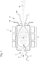
- Une installation d'implantation ionique permettant la mise en oeuvre du procédé selon l'invention est représentée schématiquement à la
figure 3 . Désignée dans son ensemble par la référence numérique générale 18, cette installation d'implantation ionique comprend une chambre à vide 20 dans l'enceinte étanche 22 de laquelle est placé un objet 24 destiné à être soumis à un procédé d'implantation ionique. L'objet 24 à traiter peut être massif ou bien se présenter à l'état de poudre. Il peut s'agir d'un matériau amorphe ou cristallin, isolant ou conducteur de l'électricité, métallique ou céramique. Dans le cas où l'objet 24 à traiter est à l'état de poudre, celle-ci sera préférentiellement agitée durant toute la durée du processus d'implantation ionique afin de s'assurer que les particules qui composent cette poudre soient exposées de manière homogène au faisceau d'implantation ionique. - Une source d'ions 26, par exemple du type à résonance cyclotron électronique ECR, est fixée de manière étanche sur l'enceinte 22 de la chambre à vide 20, en regard d'une première ouverture 28 ménagée dans cette enceinte 22. Cette source d'ions 26, d'un genre analogue à celui de la source d'ions ECR décrite ci-avant, est orientée de façon que le faisceau d'ions 30 mono- ou multichargés qu'elle produit se propage dans la chambre à vide 20 et vienne frapper la surface de l'objet 24 à traiter. Les ions mono- ou multichargés qui viennent frapper l'objet à traiter 24 pénètrent plus ou moins profondément sous la surface de cet objet 24 et s'accumulent progressivement, donnant ainsi naissance à une barrière de potentiel électrostatique qui tend à freiner et à repousser les ions qui arrivent par la suite, ce qui pose des problèmes d'inhomogénéité de la distribution des ions sur et sous la surface et dans l'épaisseur de l'objet 24 à traiter.
- Pour remédier à ce problème, une source de rayonnement ultraviolet 32 est elle aussi montée de manière étanche sur l'enceinte 22 de la chambre à vide 20, face à une seconde ouverture 34 ménagée dans l'enceinte 22. Cette source de rayonnement ultraviolet 32 est orientée de façon que le rayonnement ultraviolet 36 qu'elle produit se propage dans la chambre à vide 20 et tombe sur la surface de l'objet à traiter 24 en même temps que le faisceau d'ions 30 frappe la surface de ce même objet à traiter 24.
- Le vide qui règne dans l'enceinte étanche 22 de la chambre à vide 20 est relativement poussé, typiquement compris entre 104 et 10-4 Pa, et de préférence entre 10-2 Pa et 10-4 Pa. Néanmoins, malgré le vide assez poussé qui règne dans la chambre à vide 20, il subsiste dans l'atmosphère de cette chambre à vide 20 des atomes et des molécules auxquels les photons du rayonnement ultraviolet 36 vont arracher des électrons qui vont être attirés par le potentiel positif de la surface de l'objet à traiter 24 et vont se recombiner avec les ions présents à la surface de cet objet 24, de façon à annuler les charges électrostatiques. Le potentiel électrostatique de l'objet à traiter 24 peut ainsi être maintenu à des valeurs suffisamment faibles pour gêner le moins possible l'implantation de nouveaux ions et leur permettre de pénétrer suffisamment profondément sous la surface de l'objet à traiter 24.
- Pour améliorer le processus d'implantation d'ions dans l'objet à traiter 24, il peut être envisagé d'enrichir l'atmosphère de la chambre à vide 20. Pour cela, la chambre à vide 20 est munie d'une valve d'admission 38 sur laquelle est raccordée une source de gaz 40, par exemple un gaz noble tel que de l'argon ou du xénon. Cette valve d'admission 38 débouche à proximité de l'objet à traiter 24, de manière à créer localement, au voisinage de l'objet à traiter 24, une légère surpression de gaz noble plus riche en atomes.
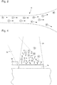
- En procédant de la sorte, on enrichit l'atmosphère de la chambre à vide 20 et on augmente le nombre d'électrons arrachés aux atomes présents dans l'atmosphère qui règne dans la chambre à vide 20 (voir
figure 4 ). Le processus de recombinaison entre les électrons dans la chambre à vide 20 et les ions à la surface de l'objet à traiter 24 est donc amplifié, ce qui permet d'abaisser encore davantage le potentiel électrique de l'objet à traiter. En effet, on s'est rendu compte avec une certaine surprise que les électrons arrachés par les photons du rayonnement ultraviolet aux atomes de gaz noble, bien qu'ils se recombinent pour partie avec des atomes ionisés du gaz noble, voire avec les ions du faisceau d'implantation ionique, se recombinent tout de même en nombre suffisamment grand avec les charges positives présentes à la surface de l'objet à traiter pour abaisser de manière sensible le potentiel électrostatique de la surface de l'objet à traiter. - Pour améliorer plus encore le processus d'implantation d'ions dans l'objet à traiter 24, il peut être envisagé de prévoir une seconde source de rayonnement ultraviolet 42. Cette seconde source de rayonnement ultraviolet 42 peut être fixée de manière étanche sur l'enceinte 22 de la chambre à vide 20, ou bien être directement installée à l'intérieur de la chambre à vide 20 en étant supportée par un pied 44. La seconde source de rayonnement ultraviolet 42 peut être orientée de façon que le rayonnement ultraviolet 46 qu'elle émet forme un angle, par exemple d'environ 90°, par rapport au rayonnement ultraviolet 36 émis par la première source de rayonnement ultraviolet 32. Avec un tel agencement des sources de rayonnement ultraviolet 32, 42, il est possible de traiter des objets 24 de plus grandes dimensions.
- Il va de soi que la présente invention n'est pas limitée aux modes de réalisation qui viennent d'être décrits et que diverses modifications et variantes simples peuvent être envisagées par l'homme du métier sans sortir du cadre de l'invention tel que défini par les revendications annexées.
- On notera en particulier que la présente invention s'applique notamment au traitement de surface d'objets en saphir (naturel ou synthétique) pour la production de verres de montres. Grâce au procédé d'implantation ionique selon l'invention, on diminue significativement la quantité de lumière incidente réfléchie par de tels verres, ce qui améliore significativement la lisibilité des informations affichées par les organes indicateurs (aiguilles, quantième, décors) situés sous ces verres.
- La présente invention s'applique également au traitement de surface d'objets métalliques cristallins ou amorphes ou de céramiques dont les propriétés mécaniques, notamment la résistance aux rayures, sont grandement améliorées lorsqu'on leur applique le procédé d'implantation ionique avec neutralisation de charges selon l'invention.
- La présente invention s'applique aussi au traitement de surface de particules d'un matériau métallique ou céramique à l'état de poudre. Les particules de poudre métallique ou céramique obtenues grâce au procédé selon l'invention sont destinées à la fabrication de pièces massives grâce à des procédés de métallurgie des poudres tels que le procédé de moulage par injection, mieux connu sous sa dénomination anglo-saxonne Metal Injection Moulding ou MIM, le pressage ou bien encore la fabrication additive comme l'impression laser tridimensionnelle.
- Selon des formes particulières de mise en oeuvre du procédé selon l'invention :
- la source d'ions mono- ou multichargés est du type à résonance cyclotron électronique ECR ;
- les ions sont accélérés sous une tension comprise entre 15'000 volts et 40'000 volts ;
- le matériau à partir duquel le faisceau d'ions est produit est choisi parmi l'azote N, le carbone C, l'oxygène O, l'argon Ar, l'hélium He et le néon Ne ;
- la dose d'ions implantés est comprise entre 1*1014 ions.cm-2 et 7.5.1017 ions.cm-2, et de préférence entre 1*1016 ions.cm-2 et 15*1016 ions.cm-2 ;
- la profondeur d'implantation des ions est de 150 nm à 250 nm ;
- le matériau métallique est un métal précieux choisi parmi l'or et le platine ;
- le matériau métallique est un métal non précieux choisi parmi le magnésium, le titane et l'aluminium ;
- on agite les particules de la poudre métallique ou céramique durant toute la durée du processus d'implantation ionique ;
- la granulométrie des particules de la poudre métallique ou céramique utilisée est telle que sensiblement 50% de l'ensemble de ces particules a une dimension inférieure à 2 micromètres, la dimension des particules de la poudre métallique ou céramique utilisée n'excédant pas 60 micromètres ;
- le matériau céramique traité selon le procédé d'implantation ionique conforme à la présente invention est un carbure, en particulier un carbure de titane TiC ou un carbure de silicium SiC ;
- le matériau céramique de type carbure est bombardé au moyen d'ions azote N pour former un carbonitrure, notamment du carbonitrure de titane TiCN ou bien du carbonitrure de silicium SiCN ;
- le matériau céramique traité selon le procédé d'implantation ionique selon l'invention est un nitrure, en particulier un nitrure de silicium Si3N4 ;
- le matériau céramique traité selon le procédé d'implantation ionique conforme à la présente invention est un oxyde, notamment de la zircone ZrO2 ou de l'alumine Al2O3 ;
- le matériau céramique de type oxyde est bombardé au moyen d'ions azote pour former un oxynitrure, notamment de l'oxynitrure de zircone ZrO(NO3)2, voire du nitrure de zirconium ZrN si l'on prolonge le bombardement ionique suffisamment longtemps, ou bien encore du nitrure d'alumine AlOxNy ;
- le matériau céramique de type oxyde est bombardé au moyen d'ions carbone pour former un carbonitrure, notamment du carbure de zircone ZrO2C, voire du carbure de zirconium ZrC ;
- le matériau céramique de type oxyde est bombardé au moyen d'ions bore pour former un oxyborure, notamment du borure de zircone ZrO2 B, voire du borure de zircone ZrB2 si l'on prolonge le bombardement ionique suffisamment longtemps.
-
- 1. Source d'ions multichargés du type à résonance cyclotron électronique ECR
- 2. Etage d'injection
- 4. Volume de gaz à ioniser
- 6. Onde hyperfréquence
- 8. Etage de confinement magnétique
- 10. Plasma
- 12. Etage d'extraction
- 14a. Anode
- 14b. Cathode
- 16. Faisceau d'ions mono- ou multichargés
- 18. Installation d'implantation ionique
- 20. Chambre à vide
- 22. Enceinte étanche
- 24. Objet à traiter
- 26. Source d'ions
- 28. Première ouverture
- 30. Faisceau d'ions mono- ou multichargés
- 32. Source de rayonnement ultraviolet
- 34. Seconde ouverture
- 36. Rayonnement ultraviolet
- 38. Valve d'admission
- 40. Source de gaz
- 42. Seconde source de rayonnement ultraviolet
- 44. Pied
- 46. Rayonnement ultraviolet
Claims (19)
- Procédé d'implantation d'ions mono- ou multichargés sur une surface d'un objet à traiter (24) placé dans une chambre à vide (20), ce procédé comprenant l'étape qui consiste simultanément :- à injecter dans la chambre à vide (20) un faisceau d'ions (30) produit par une source d'ions (26) et à diriger ce faisceau d'ions (30) vers la surface de l'objet à traiter (24), et- à éclairer la surface de l'objet à traiter (24) au moyen d'une source de rayonnement ultraviolet (32) produisant un rayonnement ultraviolet (36) qui se propage dans la chambre à vide (20).
- Procédé selon la revendication 1, caractérisé en ce que la source d'ions (26) est du type à résonance cyclotron électronique.
- Procédé selon l'une des revendications 1 ou 2, caractérisé en ce que, durant le processus d'implantation ionique, on injecte un gaz dans la chambre à vide.
- Procédé selon la revendication 3, caractérisé en ce que le gaz injecté est un gaz noble.
- Procédé selon l'une des revendications 1 à 4, caractérisé en ce que la pression atmosphérique à l'intérieur de la chambre à vide (20) est comprise entre 104 et 10-4 Pa et, de préférence entre 10-2 Pa et 10-4 Pa.
- Procédé selon l'une des revendications 1 à 5, caractérisé en ce que l'on éclaire la surface de l'objet à traiter (24) au moyen d'une seconde source de rayonnement ultraviolet (42) produisant un second rayonnement ultraviolet (46) qui se propage dans la chambre à vide (20) selon une direction formant un angle avec le premier rayonnement ultraviolet (36).
- Procédé selon l'une des revendications 1 à 6, caractérisé en ce que l'objet à traiter (30) est réalisé en un matériau non conducteur de l'électricité ou semi-conducteur.
- Procédé selon la revendication 7, caractérisé en ce que le matériau dans lequel l'objet à traiter (24) est réalisé est choisi dans le groupe formé par les saphirs naturels et synthétiques, les verres minéraux, les polymères et les céramiques.
- Procédé selon l'une des revendications 1 à 6, caractérisé en ce que le matériau dans lequel l'objet à traiter (24) est réalisé est en un matériau conducteur de l'électricité.
- Procédé selon la revendication 9, caractérisé en ce que le matériau dans lequel l'objet à traiter (30) est réalisé est choisi dans le groupe formé par les alliages métalliques cristallins ou amorphes, les céramiques et les métaux précieux et non précieux.
- Procédé selon l'une des revendications 1 à 10, caractérisé en ce que les atomes qui sont implantés dans la surface de l'objet à traiter (30) au moyen de la source d'ions (26) sont choisis dans le groupe formé par l'azote N, le carbone C, l'oxygène O, l'argon Ar, l'hélium He et le néon Ne.
- Procédé selon l'une des revendications 1 à 11, caractérisé en ce que l'on traite la surface de l'objet à traiter (30) au moyen d'une dose d'implantation ionique qui se trouve dans un intervalle compris entre 1*1014 ions.cm-2 et 7.5.1017 ions.cm-2, et de préférence entre 1*1016 ions.cm-2 et 15*1016 ions.cm-2, et en ce que la tension d'accélération des ions est comprise entre 7,5 kV et 40 kV.
- Installation d'implantation d'ions mono- ou multichargés dans une surface d'un objet à traiter (24), cette installation (28) comprenant une chambre à vide (20) dans laquelle est disposé l'objet à traiter (24), l'installation (18) comprenant également une source d'ions (26) qui injecte dans la chambre à vide (20) un faisceau d'ions (30), ce faisceau d'ions (30) étant dirigé vers la surface de l'objet à traiter (24), l'installation (18) comprenant aussi une source de rayonnement ultraviolet (32) produisant un rayonnement ultraviolet (36) qui se propage dans la chambre à vide (20) et qui éclaire l'objet à traiter (24), la source d'ions (26) et la source de rayonnement ultraviolet (32) étant agencés pour fonctionner simultanément.
- Installation d'implantation d'ions mono- ou multichargés selon la revendication 13, caractérisée en ce que la source d'ions (26) est du type à résonance cyclotron électronique.
- Installation d'implantation d'ions mono- ou multichargés selon l'une des revendications 13 ou 14, caractérisée en ce qu'elle comprend une source de gaz (40) qui délivre du gaz dans la chambre à vide (20) via une valve d'admission (38) à laquelle la source de gaz (40) est raccordée.
- Installation d'implantation d'ion mono- ou multichargés selon la revendication 14, caractérisée en ce que le gaz contenu dans la source de gaz (40) est un gaz noble.
- Installation d'implantation d'ions mono- ou multichargés selon l'une des revendications 13 à 16, caractérisée en ce qu'elle produit une dose d'implantation ionique dans un intervalle compris entre 1*1014 ions.cm-2 et 7.5.1017 ions.cm-2, et de préférence entre 1*1016 ions.cm-2 et 15*1016 ions.cm-2, et en ce la tension d'accélération des ions est comprise entre 7,5 kV et 40 kV.
- Installation d'implantation d'ions mono- ou multichargés selon l'une des revendications 13 à 17, caractérisée en que la pression atmosphérique à l'intérieur de la chambre à vide (20) est comprise entre 104 Pa et 10-4 Pa, et de préférence entre 10-2 Pa et 10-4 Pa.
- Installation d'implantation d'ions mono- ou multichargés selon l'une des revendications 13 à 18, caractérisée en ce qu'elle comprend une seconde source de rayonnement ultraviolet (42) qui éclaire la surface de l'objet à traiter (24) avec un second rayonnement ultraviolet (46) qui se propage dans la chambre à vide (20) selon une direction formant un angle avec le premier rayonnement ultraviolet (36).
Priority Applications (8)
| Application Number | Priority Date | Filing Date | Title |
|---|---|---|---|
| EP17209168.8A EP3503159B1 (fr) | 2017-12-20 | 2017-12-20 | Procédé d'implantation d'ions sur une surface d'un objet à traiter |
| EP21151991.3A EP3843123B1 (fr) | 2017-12-20 | 2017-12-20 | Installation d'implantation d'ions dans la surface d'un objet à traiter |
| US16/210,004 US20190189394A1 (en) | 2017-12-20 | 2018-12-05 | Method for implanting ions on a surface of an object to be treated and installation for implementing this method |
| TW107143880A TWI779138B (zh) | 2017-12-20 | 2018-12-06 | 在待處理的物件表面上植入離子的方法及實施此方法的設備 |
| JP2018234224A JP6985244B2 (ja) | 2017-12-20 | 2018-12-14 | 被処理物体の表面上にイオンを注入する方法 |
| KR1020180165457A KR102177593B1 (ko) | 2017-12-20 | 2018-12-19 | 처리될 오브젝트의 표면에 이온을 주입하기 위한 방법 및 이 방법을 구현하기 위한 장치 |
| CN201811566500.6A CN109950118B (zh) | 2017-12-20 | 2018-12-19 | 在待处理对象表面上注入离子的方法及实现该方法的装置 |
| JP2020126819A JP6997836B2 (ja) | 2017-12-20 | 2020-07-27 | 被処理物体の表面上にイオンを注入するための設備 |
Applications Claiming Priority (1)
| Application Number | Priority Date | Filing Date | Title |
|---|---|---|---|
| EP17209168.8A EP3503159B1 (fr) | 2017-12-20 | 2017-12-20 | Procédé d'implantation d'ions sur une surface d'un objet à traiter |
Related Child Applications (2)
| Application Number | Title | Priority Date | Filing Date |
|---|---|---|---|
| EP21151991.3A Division EP3843123B1 (fr) | 2017-12-20 | 2017-12-20 | Installation d'implantation d'ions dans la surface d'un objet à traiter |
| EP21151991.3A Division-Into EP3843123B1 (fr) | 2017-12-20 | 2017-12-20 | Installation d'implantation d'ions dans la surface d'un objet à traiter |
Publications (2)
| Publication Number | Publication Date |
|---|---|
| EP3503159A1 true EP3503159A1 (fr) | 2019-06-26 |
| EP3503159B1 EP3503159B1 (fr) | 2021-05-05 |
Family
ID=60915277
Family Applications (2)
| Application Number | Title | Priority Date | Filing Date |
|---|---|---|---|
| EP17209168.8A Active EP3503159B1 (fr) | 2017-12-20 | 2017-12-20 | Procédé d'implantation d'ions sur une surface d'un objet à traiter |
| EP21151991.3A Active EP3843123B1 (fr) | 2017-12-20 | 2017-12-20 | Installation d'implantation d'ions dans la surface d'un objet à traiter |
Family Applications After (1)
| Application Number | Title | Priority Date | Filing Date |
|---|---|---|---|
| EP21151991.3A Active EP3843123B1 (fr) | 2017-12-20 | 2017-12-20 | Installation d'implantation d'ions dans la surface d'un objet à traiter |
Country Status (6)
| Country | Link |
|---|---|
| US (1) | US20190189394A1 (fr) |
| EP (2) | EP3503159B1 (fr) |
| JP (2) | JP6985244B2 (fr) |
| KR (1) | KR102177593B1 (fr) |
| CN (1) | CN109950118B (fr) |
| TW (1) | TWI779138B (fr) |
Families Citing this family (2)
| Publication number | Priority date | Publication date | Assignee | Title |
|---|---|---|---|---|
| EP4001453A1 (fr) * | 2020-11-19 | 2022-05-25 | The Swatch Group Research and Development Ltd | Procede de depot d'une couche metallique decorative et/ou fonctionnelle sur une surface d'un article realise en un materiau ceramique electriquement non-conducteur |
| EP4071268A1 (fr) * | 2021-04-08 | 2022-10-12 | Comadur S.A. | Procédé de coloration d'un métal et metal coloré |
Citations (6)
| Publication number | Priority date | Publication date | Assignee | Title |
|---|---|---|---|---|
| US5354986A (en) * | 1991-11-12 | 1994-10-11 | Mitsubishi Denki Kabushiki Kaisha | Ion implantation apparatus |
| JPH0714761A (ja) * | 1991-07-25 | 1995-01-17 | Tadahiro Omi | 帯電物体の中和装置 |
| US5522935A (en) * | 1992-02-28 | 1996-06-04 | Nec Corporation | Plasma CVD apparatus for manufacturing a semiconductor device |
| US20070187615A1 (en) * | 2006-02-14 | 2007-08-16 | Varian Semiconductor Equipment Associates, Inc. | Wafer charge monitoring |
| WO2016062779A1 (fr) * | 2014-10-24 | 2016-04-28 | Agc Glass Europe | Procédé d'implantation d'ions et substrats en verre à ions implantés |
| WO2017027165A1 (fr) * | 2015-08-07 | 2017-02-16 | Varian Semiconductor Equipment Associates, Inc. | Appareil et techniques pour traiter des substrats au moyen de plasma directionnel et de gaz réactif |
Family Cites Families (20)
| Publication number | Priority date | Publication date | Assignee | Title |
|---|---|---|---|---|
| JPS5985858A (ja) * | 1982-11-09 | 1984-05-17 | Toshiba Corp | イオン注入装置 |
| JPS6459811A (en) * | 1987-08-31 | 1989-03-07 | Oki Electric Ind Co Ltd | Ion implantation into semiconductor device and apparatus therefor |
| JPH01119668A (ja) | 1987-10-30 | 1989-05-11 | Nec Corp | イオン注入装置 |
| JP2780419B2 (ja) * | 1990-03-05 | 1998-07-30 | 松下電器産業株式会社 | 不純物の導入装置及びその導入方法 |
| JPH0547870A (ja) * | 1991-08-20 | 1993-02-26 | Tadahiro Omi | 荷電粒子流照射装置 |
| US5911832A (en) * | 1996-10-10 | 1999-06-15 | Eaton Corporation | Plasma immersion implantation with pulsed anode |
| JPH10312765A (ja) * | 1997-05-15 | 1998-11-24 | Hitachi Ltd | 荷電粒子線装置及び荷電粒子線を用いた試料の処理方法 |
| KR100307806B1 (ko) * | 1998-12-23 | 2001-11-30 | 김윤 | 이온빔을이용하여표면개질된고분자멤브레인및그표면개질방법 |
| US6465795B1 (en) * | 2000-03-28 | 2002-10-15 | Applied Materials, Inc. | Charge neutralization of electron beam systems |
| JP4124437B2 (ja) * | 2002-11-20 | 2008-07-23 | 株式会社アルバック | イオン注入装置およびイオン注入方法 |
| JP4796791B2 (ja) * | 2005-06-08 | 2011-10-19 | 株式会社ホロン | 荷電粒子線装置および荷電粒子線像生成方法 |
| JP2007026987A (ja) * | 2005-07-20 | 2007-02-01 | Horon:Kk | 荷電粒子線装置および荷電粒子線像生成方法 |
| JP2010277871A (ja) * | 2009-05-29 | 2010-12-09 | Toyo Univ | 電子サイクロトロン共鳴イオン源装置 |
| JP2013229106A (ja) * | 2012-04-24 | 2013-11-07 | Medical Ion Technology Co Ltd | 高分子材料用イオンビーム照射装置 |
| JP2014157758A (ja) * | 2013-02-18 | 2014-08-28 | Sumitomo Heavy Ind Ltd | マイクロ波イオン源及びその起動方法 |
| US9416442B2 (en) * | 2013-03-02 | 2016-08-16 | Apple Inc. | Sapphire property modification through ion implantation |
| CN104733376A (zh) * | 2013-12-20 | 2015-06-24 | 中芯国际集成电路制造(上海)有限公司 | 金属互连结构的制作方法 |
| KR102320294B1 (ko) * | 2014-05-23 | 2021-11-01 | 아이오닉스 프랑스 | 방현성 사파이어 소재 제조용 단일 및/또는 다중 하전 가스 이온 빔 처리 방법 |
| US9824857B2 (en) | 2016-01-14 | 2017-11-21 | Varian Semiconductor Equipment Associates, Inc. | Method for implantation of semiconductor wafers having high bulk resistivity |
| CH713929B1 (fr) * | 2017-12-20 | 2018-12-28 | Swatch Group Res & Dev Ltd | Procédé d'implantation d'ions sur une surface d'un objet à traiter et installation pour la mise en œuvre de ce procédé. |
-
2017
- 2017-12-20 EP EP17209168.8A patent/EP3503159B1/fr active Active
- 2017-12-20 EP EP21151991.3A patent/EP3843123B1/fr active Active
-
2018
- 2018-12-05 US US16/210,004 patent/US20190189394A1/en not_active Abandoned
- 2018-12-06 TW TW107143880A patent/TWI779138B/zh active
- 2018-12-14 JP JP2018234224A patent/JP6985244B2/ja active Active
- 2018-12-19 KR KR1020180165457A patent/KR102177593B1/ko active Active
- 2018-12-19 CN CN201811566500.6A patent/CN109950118B/zh active Active
-
2020
- 2020-07-27 JP JP2020126819A patent/JP6997836B2/ja active Active
Patent Citations (6)
| Publication number | Priority date | Publication date | Assignee | Title |
|---|---|---|---|---|
| JPH0714761A (ja) * | 1991-07-25 | 1995-01-17 | Tadahiro Omi | 帯電物体の中和装置 |
| US5354986A (en) * | 1991-11-12 | 1994-10-11 | Mitsubishi Denki Kabushiki Kaisha | Ion implantation apparatus |
| US5522935A (en) * | 1992-02-28 | 1996-06-04 | Nec Corporation | Plasma CVD apparatus for manufacturing a semiconductor device |
| US20070187615A1 (en) * | 2006-02-14 | 2007-08-16 | Varian Semiconductor Equipment Associates, Inc. | Wafer charge monitoring |
| WO2016062779A1 (fr) * | 2014-10-24 | 2016-04-28 | Agc Glass Europe | Procédé d'implantation d'ions et substrats en verre à ions implantés |
| WO2017027165A1 (fr) * | 2015-08-07 | 2017-02-16 | Varian Semiconductor Equipment Associates, Inc. | Appareil et techniques pour traiter des substrats au moyen de plasma directionnel et de gaz réactif |
Also Published As
| Publication number | Publication date |
|---|---|
| CN109950118A (zh) | 2019-06-28 |
| JP2019114536A (ja) | 2019-07-11 |
| KR102177593B1 (ko) | 2020-11-12 |
| TWI779138B (zh) | 2022-10-01 |
| TW201929056A (zh) | 2019-07-16 |
| CN109950118B (zh) | 2021-11-23 |
| EP3843123B1 (fr) | 2026-05-06 |
| EP3843123A1 (fr) | 2021-06-30 |
| US20190189394A1 (en) | 2019-06-20 |
| JP6985244B2 (ja) | 2021-12-22 |
| KR20190074998A (ko) | 2019-06-28 |
| JP6997836B2 (ja) | 2022-01-18 |
| JP2020188015A (ja) | 2020-11-19 |
| EP3503159B1 (fr) | 2021-05-05 |
Similar Documents
| Publication | Publication Date | Title |
|---|---|---|
| FR2581244A1 (fr) | Source d'ions du type triode a une seule chambre d'ionisation a excitation haute frequence et a confinement magnetique du type multipolaire | |
| Ueda et al. | Impacts of carbon impurities in hydrogen plasmas on tungsten blistering | |
| EP3453045B1 (fr) | Procede d'implantation d'ions mono- ou multicharges sur une surface d'un objet a traiter et installation pour la mise en oeuvre de ce procede | |
| EP3503159B1 (fr) | Procédé d'implantation d'ions sur une surface d'un objet à traiter | |
| US12595551B2 (en) | Method for the surface treatment of particles of a metal powder and metal powder particles obtained thereby | |
| CH713929B1 (fr) | Procédé d'implantation d'ions sur une surface d'un objet à traiter et installation pour la mise en œuvre de ce procédé. | |
| KR101101178B1 (ko) | 귀금속의 플라즈마 이온주입 장치 및 방법과 이를 이용한 귀금속 나노복합체 형성 방법 | |
| HK40010004B (zh) | 在待处理对象表面上注入离子的方法及实现该方法的装置 | |
| CN103814153B (zh) | 薄膜形成方法、薄膜形成装置、形成有覆膜的被处理物、模具以及工具 | |
| HK40010004A (en) | Method for implanting ions on a surface of an object to be treated and installation for implementing this method | |
| Santos et al. | Modification of plasma polymer films by ion implantation | |
| Liao et al. | Effects of the temperature and beam parameters on depth profiles in X-ray photoelectron spectrometry and secondary ion mass spectrometry under C60+–Ar+ cosputtering | |
| Sasaki et al. | Magnetron sputtering deposition of conductive diamond-like carbon films with embedded nanoparticles | |
| JP5238199B2 (ja) | イオンミリング装置、およびイオンミリング方法 | |
| Li-Qing et al. | Surface Erosion of GaN Bombarded by Highly Charged 208Pb q+-Ions | |
| FR3128232A1 (fr) | Procédé de fabrication d’un élément de pompage comprenant la réalisation d’un dépôt de matériau getter par pulvérisation par faisceau d’ions | |
| CN119876882A (zh) | 一种黄金加工用离子注入加硬方法 | |
| EP4071268A1 (fr) | Procédé de coloration d'un métal et metal coloré | |
| CH713040B1 (fr) | Procédé d'implantation d'ions multichargés sur une surface d'un objet à traiter et installation pour la mise en oeuvre de ce procédé. | |
| CH717541B1 (fr) | Procédé de coloration d'une pièce métallique. | |
| Karasev et al. | Influence of ion bombardment on residual stresses in diamond-like carbon films | |
| HK40004651B (zh) | 将单电荷或多电荷离子注入待处理对象表面的方法及实现该方法的装置 | |
| Rebuli et al. | Ultra-Thin Single Crystal Diamond | |
| Qiu et al. | EPITAXIAL GROWTH CONDITION OF NI FILMS DC-BIAS-SPUTTER-DEPOSITED ON MGO (001) | |
| WO2017104443A1 (fr) | Procédé de fabrication d'un substrat de saphir et substrat de saphir |
Legal Events
| Date | Code | Title | Description |
|---|---|---|---|
| PUAI | Public reference made under article 153(3) epc to a published international application that has entered the european phase |
Free format text: ORIGINAL CODE: 0009012 |
|
| STAA | Information on the status of an ep patent application or granted ep patent |
Free format text: STATUS: THE APPLICATION HAS BEEN PUBLISHED |
|
| AK | Designated contracting states |
Kind code of ref document: A1 Designated state(s): AL AT BE BG CH CY CZ DE DK EE ES FI FR GB GR HR HU IE IS IT LI LT LU LV MC MK MT NL NO PL PT RO RS SE SI SK SM TR |
|
| AX | Request for extension of the european patent |
Extension state: BA ME |
|
| STAA | Information on the status of an ep patent application or granted ep patent |
Free format text: STATUS: REQUEST FOR EXAMINATION WAS MADE |
|
| 17P | Request for examination filed |
Effective date: 20200102 |
|
| RBV | Designated contracting states (corrected) |
Designated state(s): AL AT BE BG CH CY CZ DE DK EE ES FI FR GB GR HR HU IE IS IT LI LT LU LV MC MK MT NL NO PL PT RO RS SE SI SK SM TR |
|
| STAA | Information on the status of an ep patent application or granted ep patent |
Free format text: STATUS: EXAMINATION IS IN PROGRESS |
|
| 17Q | First examination report despatched |
Effective date: 20200327 |
|
| GRAP | Despatch of communication of intention to grant a patent |
Free format text: ORIGINAL CODE: EPIDOSNIGR1 |
|
| STAA | Information on the status of an ep patent application or granted ep patent |
Free format text: STATUS: GRANT OF PATENT IS INTENDED |
|
| INTG | Intention to grant announced |
Effective date: 20201209 |
|
| GRAS | Grant fee paid |
Free format text: ORIGINAL CODE: EPIDOSNIGR3 |
|
| GRAA | (expected) grant |
Free format text: ORIGINAL CODE: 0009210 |
|
| STAA | Information on the status of an ep patent application or granted ep patent |
Free format text: STATUS: THE PATENT HAS BEEN GRANTED |
|
| AK | Designated contracting states |
Kind code of ref document: B1 Designated state(s): AL AT BE BG CH CY CZ DE DK EE ES FI FR GB GR HR HU IE IS IT LI LT LU LV MC MK MT NL NO PL PT RO RS SE SI SK SM TR |
|
| REG | Reference to a national code |
Ref country code: GB Ref legal event code: FG4D Free format text: NOT ENGLISH |
|
| REG | Reference to a national code |
Ref country code: CH Ref legal event code: EP |
|
| REG | Reference to a national code |
Ref country code: AT Ref legal event code: REF Ref document number: 1390864 Country of ref document: AT Kind code of ref document: T Effective date: 20210515 |
|
| REG | Reference to a national code |
Ref country code: IE Ref legal event code: FG4D Free format text: LANGUAGE OF EP DOCUMENT: FRENCH |
|
| REG | Reference to a national code |
Ref country code: DE Ref legal event code: R096 Ref document number: 602017037992 Country of ref document: DE |
|
| REG | Reference to a national code |
Ref country code: LT Ref legal event code: MG9D |
|
| REG | Reference to a national code |
Ref country code: AT Ref legal event code: MK05 Ref document number: 1390864 Country of ref document: AT Kind code of ref document: T Effective date: 20210505 |
|
| PG25 | Lapsed in a contracting state [announced via postgrant information from national office to epo] |
Ref country code: HR Free format text: LAPSE BECAUSE OF FAILURE TO SUBMIT A TRANSLATION OF THE DESCRIPTION OR TO PAY THE FEE WITHIN THE PRESCRIBED TIME-LIMIT Effective date: 20210505 Ref country code: AT Free format text: LAPSE BECAUSE OF FAILURE TO SUBMIT A TRANSLATION OF THE DESCRIPTION OR TO PAY THE FEE WITHIN THE PRESCRIBED TIME-LIMIT Effective date: 20210505 Ref country code: BG Free format text: LAPSE BECAUSE OF FAILURE TO SUBMIT A TRANSLATION OF THE DESCRIPTION OR TO PAY THE FEE WITHIN THE PRESCRIBED TIME-LIMIT Effective date: 20210805 Ref country code: FI Free format text: LAPSE BECAUSE OF FAILURE TO SUBMIT A TRANSLATION OF THE DESCRIPTION OR TO PAY THE FEE WITHIN THE PRESCRIBED TIME-LIMIT Effective date: 20210505 Ref country code: LT Free format text: LAPSE BECAUSE OF FAILURE TO SUBMIT A TRANSLATION OF THE DESCRIPTION OR TO PAY THE FEE WITHIN THE PRESCRIBED TIME-LIMIT Effective date: 20210505 |
|
| PG25 | Lapsed in a contracting state [announced via postgrant information from national office to epo] |
Ref country code: GR Free format text: LAPSE BECAUSE OF FAILURE TO SUBMIT A TRANSLATION OF THE DESCRIPTION OR TO PAY THE FEE WITHIN THE PRESCRIBED TIME-LIMIT Effective date: 20210806 Ref country code: IS Free format text: LAPSE BECAUSE OF FAILURE TO SUBMIT A TRANSLATION OF THE DESCRIPTION OR TO PAY THE FEE WITHIN THE PRESCRIBED TIME-LIMIT Effective date: 20210905 Ref country code: LV Free format text: LAPSE BECAUSE OF FAILURE TO SUBMIT A TRANSLATION OF THE DESCRIPTION OR TO PAY THE FEE WITHIN THE PRESCRIBED TIME-LIMIT Effective date: 20210505 Ref country code: PT Free format text: LAPSE BECAUSE OF FAILURE TO SUBMIT A TRANSLATION OF THE DESCRIPTION OR TO PAY THE FEE WITHIN THE PRESCRIBED TIME-LIMIT Effective date: 20210906 Ref country code: NO Free format text: LAPSE BECAUSE OF FAILURE TO SUBMIT A TRANSLATION OF THE DESCRIPTION OR TO PAY THE FEE WITHIN THE PRESCRIBED TIME-LIMIT Effective date: 20210805 Ref country code: PL Free format text: LAPSE BECAUSE OF FAILURE TO SUBMIT A TRANSLATION OF THE DESCRIPTION OR TO PAY THE FEE WITHIN THE PRESCRIBED TIME-LIMIT Effective date: 20210505 Ref country code: RS Free format text: LAPSE BECAUSE OF FAILURE TO SUBMIT A TRANSLATION OF THE DESCRIPTION OR TO PAY THE FEE WITHIN THE PRESCRIBED TIME-LIMIT Effective date: 20210505 Ref country code: SE Free format text: LAPSE BECAUSE OF FAILURE TO SUBMIT A TRANSLATION OF THE DESCRIPTION OR TO PAY THE FEE WITHIN THE PRESCRIBED TIME-LIMIT Effective date: 20210505 |
|
| REG | Reference to a national code |
Ref country code: NL Ref legal event code: MP Effective date: 20210505 |
|
| PG25 | Lapsed in a contracting state [announced via postgrant information from national office to epo] |
Ref country code: NL Free format text: LAPSE BECAUSE OF FAILURE TO SUBMIT A TRANSLATION OF THE DESCRIPTION OR TO PAY THE FEE WITHIN THE PRESCRIBED TIME-LIMIT Effective date: 20210505 |
|
| PG25 | Lapsed in a contracting state [announced via postgrant information from national office to epo] |
Ref country code: SK Free format text: LAPSE BECAUSE OF FAILURE TO SUBMIT A TRANSLATION OF THE DESCRIPTION OR TO PAY THE FEE WITHIN THE PRESCRIBED TIME-LIMIT Effective date: 20210505 Ref country code: SM Free format text: LAPSE BECAUSE OF FAILURE TO SUBMIT A TRANSLATION OF THE DESCRIPTION OR TO PAY THE FEE WITHIN THE PRESCRIBED TIME-LIMIT Effective date: 20210505 Ref country code: CZ Free format text: LAPSE BECAUSE OF FAILURE TO SUBMIT A TRANSLATION OF THE DESCRIPTION OR TO PAY THE FEE WITHIN THE PRESCRIBED TIME-LIMIT Effective date: 20210505 Ref country code: EE Free format text: LAPSE BECAUSE OF FAILURE TO SUBMIT A TRANSLATION OF THE DESCRIPTION OR TO PAY THE FEE WITHIN THE PRESCRIBED TIME-LIMIT Effective date: 20210505 Ref country code: DK Free format text: LAPSE BECAUSE OF FAILURE TO SUBMIT A TRANSLATION OF THE DESCRIPTION OR TO PAY THE FEE WITHIN THE PRESCRIBED TIME-LIMIT Effective date: 20210505 Ref country code: RO Free format text: LAPSE BECAUSE OF FAILURE TO SUBMIT A TRANSLATION OF THE DESCRIPTION OR TO PAY THE FEE WITHIN THE PRESCRIBED TIME-LIMIT Effective date: 20210505 Ref country code: ES Free format text: LAPSE BECAUSE OF FAILURE TO SUBMIT A TRANSLATION OF THE DESCRIPTION OR TO PAY THE FEE WITHIN THE PRESCRIBED TIME-LIMIT Effective date: 20210505 |
|
| REG | Reference to a national code |
Ref country code: DE Ref legal event code: R097 Ref document number: 602017037992 Country of ref document: DE |
|
| PLBE | No opposition filed within time limit |
Free format text: ORIGINAL CODE: 0009261 |
|
| STAA | Information on the status of an ep patent application or granted ep patent |
Free format text: STATUS: NO OPPOSITION FILED WITHIN TIME LIMIT |
|
| 26N | No opposition filed |
Effective date: 20220208 |
|
| PG25 | Lapsed in a contracting state [announced via postgrant information from national office to epo] |
Ref country code: IS Free format text: LAPSE BECAUSE OF FAILURE TO SUBMIT A TRANSLATION OF THE DESCRIPTION OR TO PAY THE FEE WITHIN THE PRESCRIBED TIME-LIMIT Effective date: 20210905 Ref country code: AL Free format text: LAPSE BECAUSE OF FAILURE TO SUBMIT A TRANSLATION OF THE DESCRIPTION OR TO PAY THE FEE WITHIN THE PRESCRIBED TIME-LIMIT Effective date: 20210505 |
|
| PG25 | Lapsed in a contracting state [announced via postgrant information from national office to epo] |
Ref country code: MC Free format text: LAPSE BECAUSE OF FAILURE TO SUBMIT A TRANSLATION OF THE DESCRIPTION OR TO PAY THE FEE WITHIN THE PRESCRIBED TIME-LIMIT Effective date: 20210505 Ref country code: IT Free format text: LAPSE BECAUSE OF FAILURE TO SUBMIT A TRANSLATION OF THE DESCRIPTION OR TO PAY THE FEE WITHIN THE PRESCRIBED TIME-LIMIT Effective date: 20210505 |
|
| PG25 | Lapsed in a contracting state [announced via postgrant information from national office to epo] |
Ref country code: LU Free format text: LAPSE BECAUSE OF NON-PAYMENT OF DUE FEES Effective date: 20211220 Ref country code: IE Free format text: LAPSE BECAUSE OF NON-PAYMENT OF DUE FEES Effective date: 20211220 |
|
| PG25 | Lapsed in a contracting state [announced via postgrant information from national office to epo] |
Ref country code: CY Free format text: LAPSE BECAUSE OF FAILURE TO SUBMIT A TRANSLATION OF THE DESCRIPTION OR TO PAY THE FEE WITHIN THE PRESCRIBED TIME-LIMIT Effective date: 20210505 |
|
| P01 | Opt-out of the competence of the unified patent court (upc) registered |
Effective date: 20230615 |
|
| PG25 | Lapsed in a contracting state [announced via postgrant information from national office to epo] |
Ref country code: HU Free format text: LAPSE BECAUSE OF FAILURE TO SUBMIT A TRANSLATION OF THE DESCRIPTION OR TO PAY THE FEE WITHIN THE PRESCRIBED TIME-LIMIT; INVALID AB INITIO Effective date: 20171220 |
|
| PG25 | Lapsed in a contracting state [announced via postgrant information from national office to epo] |
Ref country code: MK Free format text: LAPSE BECAUSE OF FAILURE TO SUBMIT A TRANSLATION OF THE DESCRIPTION OR TO PAY THE FEE WITHIN THE PRESCRIBED TIME-LIMIT Effective date: 20210505 |
|
| PG25 | Lapsed in a contracting state [announced via postgrant information from national office to epo] |
Ref country code: MT Free format text: LAPSE BECAUSE OF FAILURE TO SUBMIT A TRANSLATION OF THE DESCRIPTION OR TO PAY THE FEE WITHIN THE PRESCRIBED TIME-LIMIT Effective date: 20210505 |
|
| PG25 | Lapsed in a contracting state [announced via postgrant information from national office to epo] |
Ref country code: TR Free format text: LAPSE BECAUSE OF FAILURE TO SUBMIT A TRANSLATION OF THE DESCRIPTION OR TO PAY THE FEE WITHIN THE PRESCRIBED TIME-LIMIT Effective date: 20210505 |
|
| REG | Reference to a national code |
Ref country code: CH Ref legal event code: U11 Free format text: ST27 STATUS EVENT CODE: U-0-0-U10-U11 (AS PROVIDED BY THE NATIONAL OFFICE) Effective date: 20260101 |
|
| PGFP | Annual fee paid to national office [announced via postgrant information from national office to epo] |
Ref country code: DE Payment date: 20251126 Year of fee payment: 9 |
|
| PGFP | Annual fee paid to national office [announced via postgrant information from national office to epo] |
Ref country code: GB Payment date: 20251120 Year of fee payment: 9 |
|
| PGFP | Annual fee paid to national office [announced via postgrant information from national office to epo] |
Ref country code: FR Payment date: 20251120 Year of fee payment: 9 |
|
| PGFP | Annual fee paid to national office [announced via postgrant information from national office to epo] |
Ref country code: BE Payment date: 20251119 Year of fee payment: 9 |
|
| PGFP | Annual fee paid to national office [announced via postgrant information from national office to epo] |
Ref country code: CH Payment date: 20260101 Year of fee payment: 9 |