EP3503150A1 - Method for operating the drive of a vacuum interrupter, and vacuum interrupter itself - Google Patents
Method for operating the drive of a vacuum interrupter, and vacuum interrupter itself Download PDFInfo
- Publication number
- EP3503150A1 EP3503150A1 EP17209273.6A EP17209273A EP3503150A1 EP 3503150 A1 EP3503150 A1 EP 3503150A1 EP 17209273 A EP17209273 A EP 17209273A EP 3503150 A1 EP3503150 A1 EP 3503150A1
- Authority
- EP
- European Patent Office
- Prior art keywords
- opening
- phase
- vacuum interrupter
- movement
- drive
- Prior art date
- Legal status (The legal status is an assumption and is not a legal conclusion. Google has not performed a legal analysis and makes no representation as to the accuracy of the status listed.)
- Granted
Links
Images


Classifications
-
- H—ELECTRICITY
- H01—ELECTRIC ELEMENTS
- H01H—ELECTRIC SWITCHES; RELAYS; SELECTORS; EMERGENCY PROTECTIVE DEVICES
- H01H33/00—High-tension or heavy-current switches with arc-extinguishing or arc-preventing means
- H01H33/60—Switches wherein the means for extinguishing or preventing the arc do not include separate means for obtaining or increasing flow of arc-extinguishing fluid
- H01H33/66—Vacuum switches
- H01H33/666—Operating arrangements
-
- H—ELECTRICITY
- H01—ELECTRIC ELEMENTS
- H01H—ELECTRIC SWITCHES; RELAYS; SELECTORS; EMERGENCY PROTECTIVE DEVICES
- H01H9/00—Details of switching devices, not covered by groups H01H1/00 - H01H7/00
- H01H9/30—Means for extinguishing or preventing arc between current-carrying parts
-
- H—ELECTRICITY
- H01—ELECTRIC ELEMENTS
- H01H—ELECTRIC SWITCHES; RELAYS; SELECTORS; EMERGENCY PROTECTIVE DEVICES
- H01H9/00—Details of switching devices, not covered by groups H01H1/00 - H01H7/00
- H01H9/30—Means for extinguishing or preventing arc between current-carrying parts
- H01H2009/307—Means for extinguishing or preventing arc between current-carrying parts with slow break, e.g. for AC current waiting for a zero crossing
Definitions
- the invention relates to a method for operating the drive of a vacuum interrupter in opening modus, wherein the opening movement of at least one movable contact is divided into serial phases, an opening phase and an isolating phase, driven in at least two different velocities, according to preamble of claims 1 and 4.
- the electrical strength is increased while the oscillation of the load circuit takes place.
- the electrical strength is increasing fast, and it takes a relatively long time until the next breakdown occurs.
- the breakdown voltage will then have a relatively high value with the consequence of a high electrical stress of the load.
- slow opening of the VI the electrical strength is increasing slowly, and it takes only a relatively short time until the next breakdown occurs.
- the breakdown voltage will then have a relatively low value with the consequence of a relatively low electrical stress of the load, as the magnitude of the voltage step is reduced.
Landscapes
- High-Tension Arc-Extinguishing Switches Without Spraying Means (AREA)
- Driving Mechanisms And Operating Circuits Of Arc-Extinguishing High-Tension Switches (AREA)
Abstract
Description
- The invention relates to a method for operating the drive of a vacuum interrupter in opening modus, wherein the opening movement of at least one movable contact is divided into serial phases, an opening phase and an isolating phase, driven in at least two different velocities, according to preamble of
claims 1 and 4. - CIRCUIT BREAKER with vacuum interrupters (VI) are usually being designed for closing and opening under short circuit conditions. Regarding the opening operation, the increase of the distance of the separated contacts of the VI has to be fast; otherwise there is a risk that the arc re-ignites after the first current zero because of the low distance of the contacts and accordingly because of the low electric strength of the VI. Under short circuit conditions, this arc generates considerable heat in the contacts of the VI, which can damage the contacts.
- Not considering short circuit currents, but nominal loads, like e.g. motors or transformers, having mainly a resistance RLoad and an inductance LLoad, the opening of the VI contacts can generate reignitions. This effect occurs after the load current is interrupted by the VI. The energies that are inside the load circuit and inside the stray capacitance CCable of the cable between the VI and the load will start to oscillate. This oscillation will generate a sinusoidal voltage at the cable with a typically higher frequency than the frequency of the network. The magnitude of the voltage of this oscillation will typically be higher than the voltage of the network. The resulting voltage at the open contacts of the VI can therefore reach high values, that can also be higher than the momentary electric strength of the VI, as the VI contacts are still in the phase where their distance is increased and the full electric strength is not yet reached. The electric breakdown that then can occur will result in a very fast change of the voltage over the VI contacts and also in a very fast change of the voltage at the side of the cable that is connected to the CIRCUIT BREAKER. This voltage step will travel through the cable and can damage the insulation of the windings of the load.
- Often, the load is protected by additional means like snubber circuits or voltage arrestors. The latter reduce the magnitude and the probability of the voltage steps.
- In a well known state of the art (
EP 1 292 960 B1 - So, it is the object of the invention, to steer the opening movement of a vacuum interrupter in such, that in case of nominal or less load current, the inductive energy of the complete electrical circuit will be damped more effectively.
- The present invention proposes to open the VI intentionally slow in case of a nominal load current interruption, to reduce the magnitude of the voltage steps of possible re-ignitions.
- Referred to what is said to the state of the art above, basical for the invention is, that in difference to the above cited state of the art, the velocities will be used in an inverted way.
That means, if a nominal or less current load will be detected, the closed contacts are opened with a slower velocity during the opening phase, and with a higher velocity during the isolation phase.
So, that means, the invention is, that in the opening phase, the velocity of the opening movement is lower, than in the isolating phase.
This is definitively inverted, to the well known proceeding in the aforesaid state of the art. - In an advantageous embodiment for the method, the aforesaid opening movement will be initiated via the drive, if on the referring electrical circuit actually a lower, not maximal current load is detected via a current sensor. This is the case for the normal service condition, i.e. the method presented here is not intended for interrupting short cicuit currents. To avoid high thermal stress at the contacts in case of currents that are higher than the nominal load current, the drive and control of the CIRCUIT BREAKER shall be able to distinguish between the interruption of a nominal load current and a short circuit current. Currents distinctly higher than the nominal load current, or short circuit currents, shall be interrupted with a high speed opening movement of the contacts, comparable to a state of the art CIRCUIT BREAKER.
- In a further advantageous embodiment, the voltage oscillation in the cable of the switched circuit is measured, and the switching movement velocity is additionally steered along the switching movement, by actual consideration of the amplitude of aforesaid detected voltage oscillation.
- According to a vacuum interrupter, operated according to the aforesaid method, the invention is, that in the opening phase the velocity of the opening movement is steered via a drive controller as being lower, than in the isolating phase.
- In a further advantageous embodiment, the drive controller is communicating with a current sensor, placed in the electrical circuit of the vacuum switch, in such, that the aforesaid opening movement will be initiated via the drive, if on the referring electrical circuit actually a lower, not maximal current load is detected via the current sensor.
- In a further advantageous embodiment, the drive controller is communicating with a voltage sensor, placed in the electrical circuit of the vacuum switch, in such, that the voltage oscillation in the cable of the switched circuit is measured, and the switching movement velocity is additionally steered along the switching movement, by actual consideration of the amplitude of aforesaid detected voltage oscillation.
In a final advantageous embodiment, the vacuum interrupter is used for medium voltage. - So in the invention, the velocities are inverted in comparison to the well known switching characteristics.
- During the opening of the VI, the electrical strength is increased while the oscillation of the load circuit takes place.
With fast opening of the VI, the electrical strength is increasing fast, and it takes a relatively long time until the next breakdown occurs. The breakdown voltage will then have a relatively high value with the consequence of a high electrical stress of the load.
With slow opening of the VI, the electrical strength is increasing slowly, and it takes only a relatively short time until the next breakdown occurs. The breakdown voltage will then have a relatively low value with the consequence of a relatively low electrical stress of the load, as the magnitude of the voltage step is reduced. - An embodiment of the invention is shown in the drawing:
-
Figure 1 : The considered electrical circuit -
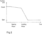
Figure 2 : The principle of opening the VI contacts slowly at first during the opening phase and then faster to reach the final position -
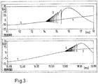
Figure 3 : Simulation showing the damping effect on the reignitions -
Figure 4 : Variant ofFigure 2 with a first fast step in the opening phase -
Figure 1 shows the considered electrical circuit comprising an AC voltage source, the VI as a switch, the cable represented by its capacity CCable and the load represented by its resistance RLoad and its inductance LLoad. -
Figure 2 shows the transition of the movable VI contact from the closed position to the open position over time. At the begin, the VI contacts are closed. During the opening phase, the movable contact is slowly driven away from the fixed contact. During the insulating phase, the movable contact is driven faster, until it has reached the fully open position.
Figure 3 shows the principal difference in a simulation of the opening operation with high speed (upper curves) and with low speed (lower curves), using the circuit shown inFigure 1 .Curves curves 2 and 4 are the voltages of CCable. With slow opening, the voltage steps of curve 4 are clearly lower than the voltage steps ofcurve 2
Using this effect, additional means for load protection, like snubber circuits or voltage arrestors, may become obsolete, depending on the actual application.
A current probe or sensor and a protection device can determine if the intended opening operation is a short circuit current opening or a nominal load current opening. In case of a short circuit current opening, the operation has to be performed with the normal VI speed, while in case of a nominal load current opening, the operation shall be performed with a reduced speed.
The design of the drive of the CIRCUIT BREAKER certainly has to support this approach, e.g. by the introduction of an additional damping device for the slow speed opening operation, or by the application of a servomotor with speed control and / or position control for driving the CIRCUIT BREAKER.
Opening with slow speed also includes the idea to change the speed during the opening operation, e.g. to obtain a certain distance of the VI contacts fast, then reducing the speed to practically maintain this distance for a longer time, until the energy of the oscillation of the load circuit is below a limit where re-ignitions can occur, and then increasing the speed again to reach the fully open position, as shown infigure 4 . - The proposed method is also advantageous for switching capacitors. In a conventional CIRCUIT BREAKER, the capacitor current will be interrupted at current zero, i.e. at the maximum of the network voltage. In case of slow opening, there will be several re-ignitions within the first 5ms after current zero, so that the remaining voltage at the capacitor can be much closer to zero.
Claims (9)
- Method for operating the drive of a vacuum interrupter in opening modus, wherein the opening movement of at least one movable contact is divided into serial phases, an opening phase and an isolating phase, driven in at least two different velocities,
characterized in that in the opening phase the velocity of the opening movement is lower, than in the isolating phase. - Method according to claim 1,
characterized in that the aforesaid opening movement will be initiated via the drive, if on the referring electrical circuit actually a current not higher than the nominal load current is detected via a current sensor. - Method according to claim 1 and 2,
characterized in that for currents that are higher than the nominal load current, the opening movement is not divided in two phases, but the relatively slow opening phase is omitted and the entire opening operation is being performed with a high speed. - Method according to claim 1 or 2,
characterized in that the voltage oscillation in the cable of the switched circuit is measured, and the switching movement velocity is additionally steered along the switching movement, by actual consideration of the amplitude of aforesaid detected voltage oscillation. - Method according to claim 1, 2 or 3,
characterized in that the opening phase is starting with a first fast step. - Vacuum interrupter with a steerable drive for switching the contacts of the vacuum interrupter, wherein the opening movement of at least one movable contact is divided into serial phases, an opening phase, a disconnecting phase, and an isolating phase, driven in at least two different velocities, operated by the method, according to at least one of claims 1 to 4,
characterized in that in the opening and/or disconnecting phase the velocity of the opening movement is steered via a drive controller as being lower, than in the isolating phase. - Vacuum interrupter according to claim5,
characterized in that the drive controller is communicating with a current sensor, placed in the electrical circuit of the vacuum switch, in such, that the aforesaid opening movement will be initiated via the drive, if on the referring electrical circuit actually a lower, not maximal current load is detected via the current sensor. - Vacuum interrupter according to claim 5 or 6,
characterized in that the drive controller is communicating with a voltage sensor, placed in the electrical circuit of the vacuum switch, in such, that the voltage oscillation in the cable of the switched circuit is measured, and the switching movement velocity is additionally steered along the switching movement, by actual consideration of the amplitude of aforesaid detected voltage oscillation. - Vacuum interrupter according to one of the claims 5 to 7, characterized in, that the vacuum interrupter is used in medium voltage.
Priority Applications (6)
| Application Number | Priority Date | Filing Date | Title |
|---|---|---|---|
| ES17209273T ES2978289T3 (en) | 2017-12-21 | 2017-12-21 | Method for operating the drive of a vacuum switch and the vacuum switch itself |
| EP17209273.6A EP3503150B1 (en) | 2017-12-21 | 2017-12-21 | Method for operating the drive of a vacuum interrupter, and vacuum interrupter itself |
| PCT/EP2018/085087 WO2019121432A1 (en) | 2017-12-21 | 2018-12-14 | Method for operating the drive of a vacuum interrupter, and vacuum interrupter itself |
| RU2020123557A RU2750175C1 (en) | 2017-12-21 | 2018-12-14 | Method for controlling vacuum interrupter drive and vacuum interrupter |
| CN201880081607.3A CN111492454B (en) | 2017-12-21 | 2018-12-14 | Method for operating a drive of a vacuum interrupter and vacuum interrupter itself |
| US16/904,580 US11152173B2 (en) | 2017-12-21 | 2020-06-18 | Method for operating the drive of a vacuum interrupter, and vacuum interrupter itself |
Applications Claiming Priority (1)
| Application Number | Priority Date | Filing Date | Title |
|---|---|---|---|
| EP17209273.6A EP3503150B1 (en) | 2017-12-21 | 2017-12-21 | Method for operating the drive of a vacuum interrupter, and vacuum interrupter itself |
Publications (2)
| Publication Number | Publication Date |
|---|---|
| EP3503150A1 true EP3503150A1 (en) | 2019-06-26 |
| EP3503150B1 EP3503150B1 (en) | 2024-02-14 |
Family
ID=60702474
Family Applications (1)
| Application Number | Title | Priority Date | Filing Date |
|---|---|---|---|
| EP17209273.6A Active EP3503150B1 (en) | 2017-12-21 | 2017-12-21 | Method for operating the drive of a vacuum interrupter, and vacuum interrupter itself |
Country Status (6)
| Country | Link |
|---|---|
| US (1) | US11152173B2 (en) |
| EP (1) | EP3503150B1 (en) |
| CN (1) | CN111492454B (en) |
| ES (1) | ES2978289T3 (en) |
| RU (1) | RU2750175C1 (en) |
| WO (1) | WO2019121432A1 (en) |
Cited By (1)
| Publication number | Priority date | Publication date | Assignee | Title |
|---|---|---|---|---|
| EP3754682B1 (en) | 2019-06-19 | 2023-08-02 | ABB Schweiz AG | An improved medium voltage switching apparatus |
Citations (4)
| Publication number | Priority date | Publication date | Assignee | Title |
|---|---|---|---|---|
| DE3815805A1 (en) * | 1988-05-09 | 1989-11-23 | Calor Emag Elektrizitaets Ag | Vacuum switch |
| US6331687B1 (en) * | 1995-05-15 | 2001-12-18 | Cooper Industries Inc. | Control method and device for a switchgear actuator |
| WO2002058091A1 (en) * | 2001-01-19 | 2002-07-25 | Siemens Aktiengesellschaft | Vacuum circuit-breaker and a method for controlling the same |
| EP1292960B1 (en) | 2000-06-20 | 2003-12-03 | Siemens Aktiengesellschaft | Method for opening the contact gap of a vacuum interrupter |
Family Cites Families (17)
| Publication number | Priority date | Publication date | Assignee | Title |
|---|---|---|---|---|
| US3920941A (en) * | 1972-08-10 | 1975-11-18 | Westinghouse Electric Corp | Contact-operating mechanism for breaking vacuum interrupter contact-welds by bending action of the movable contact rod |
| JPS5919293Y2 (en) * | 1979-07-02 | 1984-06-04 | 日新電機株式会社 | Arc rotating type cutter |
| US5747766A (en) * | 1993-03-16 | 1998-05-05 | Cooper Industries, Inc. | Operating mechanism usable with a vacuum interrupter |
| CN1085398C (en) * | 1995-05-15 | 2002-05-22 | 库帕实业公司 | Control method and device for switchgear actuator |
| JP3589061B2 (en) * | 1999-01-25 | 2004-11-17 | 株式会社日立製作所 | Vacuum switchgear and method for opening and closing vacuum switchgear |
| JP2006032121A (en) * | 2004-07-16 | 2006-02-02 | Japan Ae Power Systems Corp | High voltage circuit breaker with large capacity |
| KR100846223B1 (en) * | 2006-03-09 | 2008-07-15 | (주)서전기전 | Medium Voltage Switch-gear |
| CA2721358C (en) * | 2008-04-14 | 2016-12-20 | Aker Engineering & Technology As | Rotary transformer |
| CN101315849B (en) * | 2008-05-23 | 2010-11-10 | 西安交通大学 | Spring Operating Mechanism Matching the Opening and Closing Characteristics of 126kV Vacuum Circuit Breaker |
| CN101527223B (en) * | 2009-04-24 | 2012-05-23 | 北京华东森源电气有限责任公司 | High-voltage vacuum breaker |
| CN201392768Y (en) * | 2009-04-24 | 2010-01-27 | 北京华东森源电气有限责任公司 | High-voltage vacuum circuit breaker |
| PL2330609T3 (en) | 2009-12-04 | 2012-12-31 | Abb Technology Ag | Magnetic actuator unit for a circuit-braker arrangement |
| CN101847541B (en) * | 2010-05-26 | 2013-01-02 | 西安交通大学 | Buffer used for 126kV-vacuum circuit breaker |
| CN102290279A (en) * | 2011-06-30 | 2011-12-21 | 中国人民解放军海军工程大学 | High speed vacuum direct current (DC) current limiting circuit breaker |
| CN103311041B (en) * | 2013-03-19 | 2015-09-30 | 北京交通大学 | Permanent magnetic vacuum breaker shutting-brake control method |
| EP2830078A1 (en) * | 2013-07-26 | 2015-01-28 | ABB Technology AG | Method to determine the pressure inside of a vacuum interrupter, and vacuum interrupter itself |
| CN106971904B (en) * | 2017-05-15 | 2019-04-05 | 上海交通大学 | Vacuum circuit breaker closing transmission mechanism |
-
2017
- 2017-12-21 EP EP17209273.6A patent/EP3503150B1/en active Active
- 2017-12-21 ES ES17209273T patent/ES2978289T3/en active Active
-
2018
- 2018-12-14 CN CN201880081607.3A patent/CN111492454B/en active Active
- 2018-12-14 RU RU2020123557A patent/RU2750175C1/en active
- 2018-12-14 WO PCT/EP2018/085087 patent/WO2019121432A1/en not_active Ceased
-
2020
- 2020-06-18 US US16/904,580 patent/US11152173B2/en active Active
Patent Citations (4)
| Publication number | Priority date | Publication date | Assignee | Title |
|---|---|---|---|---|
| DE3815805A1 (en) * | 1988-05-09 | 1989-11-23 | Calor Emag Elektrizitaets Ag | Vacuum switch |
| US6331687B1 (en) * | 1995-05-15 | 2001-12-18 | Cooper Industries Inc. | Control method and device for a switchgear actuator |
| EP1292960B1 (en) | 2000-06-20 | 2003-12-03 | Siemens Aktiengesellschaft | Method for opening the contact gap of a vacuum interrupter |
| WO2002058091A1 (en) * | 2001-01-19 | 2002-07-25 | Siemens Aktiengesellschaft | Vacuum circuit-breaker and a method for controlling the same |
Cited By (1)
| Publication number | Priority date | Publication date | Assignee | Title |
|---|---|---|---|---|
| EP3754682B1 (en) | 2019-06-19 | 2023-08-02 | ABB Schweiz AG | An improved medium voltage switching apparatus |
Also Published As
| Publication number | Publication date |
|---|---|
| US11152173B2 (en) | 2021-10-19 |
| WO2019121432A1 (en) | 2019-06-27 |
| US20200321174A1 (en) | 2020-10-08 |
| RU2750175C1 (en) | 2021-06-23 |
| ES2978289T3 (en) | 2024-09-10 |
| CN111492454A (en) | 2020-08-04 |
| CN111492454B (en) | 2023-07-04 |
| EP3503150B1 (en) | 2024-02-14 |
Similar Documents
| Publication | Publication Date | Title |
|---|---|---|
| EP2289085B1 (en) | A dc current breaker | |
| CN101383243B (en) | Power switching apparatus and method of controlling the same | |
| EP2669921A1 (en) | Circuit breaker apparatus | |
| JPH03156820A (en) | Power switching control device | |
| KR20150010578A (en) | Switchgear | |
| WO2015185096A1 (en) | High voltage dc circuit breaker unit | |
| EP2097915B1 (en) | High-voltage disconnecting circuit breaker and method of operating the same | |
| CN111033661B (en) | Motor-driven vacuum circuit breaker | |
| US11152173B2 (en) | Method for operating the drive of a vacuum interrupter, and vacuum interrupter itself | |
| CN101088201B (en) | Electric power flow control | |
| CA2830763C (en) | Switch for a transmission path for high-voltage direct current | |
| WO2012045360A1 (en) | Direct current circuit breaker | |
| KR101841859B1 (en) | A circuit breaker unit with electromagnetic drive | |
| US12237652B2 (en) | Switch, gas insulated switchgear, and method for controlling switch | |
| CN102027557B (en) | Method for determining a switching time of an electrical switching device | |
| WO2017098594A1 (en) | Power switch control device | |
| WO2020055317A1 (en) | Current interrupter with actuator run-time control | |
| EP2249363A1 (en) | Arrangement, substation, operating method and use of a grounding switch for protecting an electrical circuit against short-line faults | |
| JP2016126920A (en) | High voltage current breaker | |
| CN107331571A (en) | A kind of vacuum arc-extinguishing chamber contact and its control method for switched capacitor group | |
| Kokin et al. | Features of controlled switching under normal and emergency operating conditions in medium voltage networks | |
| CN116825575B (en) | Double-break vacuum circuit breaker | |
| WO2001091151A1 (en) | Combination of a vacuum interruption device and oil-filled transformer | |
| HK1128987B (en) | Power switching apparatus and method of controlling the same | |
| Rostron et al. | Simplified designs for switching reactive power improve power system reliability |
Legal Events
| Date | Code | Title | Description |
|---|---|---|---|
| PUAI | Public reference made under article 153(3) epc to a published international application that has entered the european phase |
Free format text: ORIGINAL CODE: 0009012 |
|
| STAA | Information on the status of an ep patent application or granted ep patent |
Free format text: STATUS: THE APPLICATION HAS BEEN PUBLISHED |
|
| AK | Designated contracting states |
Kind code of ref document: A1 Designated state(s): AL AT BE BG CH CY CZ DE DK EE ES FI FR GB GR HR HU IE IS IT LI LT LU LV MC MK MT NL NO PL PT RO RS SE SI SK SM TR |
|
| AX | Request for extension of the european patent |
Extension state: BA ME |
|
| STAA | Information on the status of an ep patent application or granted ep patent |
Free format text: STATUS: REQUEST FOR EXAMINATION WAS MADE |
|
| 17P | Request for examination filed |
Effective date: 20191218 |
|
| RBV | Designated contracting states (corrected) |
Designated state(s): AL AT BE BG CH CY CZ DE DK EE ES FI FR GB GR HR HU IE IS IT LI LT LU LV MC MK MT NL NO PL PT RO RS SE SI SK SM TR |
|
| STAA | Information on the status of an ep patent application or granted ep patent |
Free format text: STATUS: EXAMINATION IS IN PROGRESS |
|
| 17Q | First examination report despatched |
Effective date: 20210614 |
|
| GRAP | Despatch of communication of intention to grant a patent |
Free format text: ORIGINAL CODE: EPIDOSNIGR1 |
|
| STAA | Information on the status of an ep patent application or granted ep patent |
Free format text: STATUS: GRANT OF PATENT IS INTENDED |
|
| INTG | Intention to grant announced |
Effective date: 20231114 |
|
| GRAS | Grant fee paid |
Free format text: ORIGINAL CODE: EPIDOSNIGR3 |
|
| GRAA | (expected) grant |
Free format text: ORIGINAL CODE: 0009210 |
|
| STAA | Information on the status of an ep patent application or granted ep patent |
Free format text: STATUS: THE PATENT HAS BEEN GRANTED |
|
| AK | Designated contracting states |
Kind code of ref document: B1 Designated state(s): AL AT BE BG CH CY CZ DE DK EE ES FI FR GB GR HR HU IE IS IT LI LT LU LV MC MK MT NL NO PL PT RO RS SE SI SK SM TR |
|
| RAP3 | Party data changed (applicant data changed or rights of an application transferred) |
Owner name: ABB SCHWEIZ AG |
|
| REG | Reference to a national code |
Ref country code: GB Ref legal event code: FG4D |
|
| REG | Reference to a national code |
Ref country code: CH Ref legal event code: EP |
|
| REG | Reference to a national code |
Ref country code: DE Ref legal event code: R096 Ref document number: 602017079112 Country of ref document: DE |
|
| REG | Reference to a national code |
Ref country code: IE Ref legal event code: FG4D |
|
| REG | Reference to a national code |
Ref country code: LT Ref legal event code: MG9D |
|
| REG | Reference to a national code |
Ref country code: NL Ref legal event code: MP Effective date: 20240214 |
|
| PG25 | Lapsed in a contracting state [announced via postgrant information from national office to epo] |
Ref country code: IS Free format text: LAPSE BECAUSE OF FAILURE TO SUBMIT A TRANSLATION OF THE DESCRIPTION OR TO PAY THE FEE WITHIN THE PRESCRIBED TIME-LIMIT Effective date: 20240614 |
|
| PG25 | Lapsed in a contracting state [announced via postgrant information from national office to epo] |
Ref country code: LT Free format text: LAPSE BECAUSE OF FAILURE TO SUBMIT A TRANSLATION OF THE DESCRIPTION OR TO PAY THE FEE WITHIN THE PRESCRIBED TIME-LIMIT Effective date: 20240214 |
|
| PG25 | Lapsed in a contracting state [announced via postgrant information from national office to epo] |
Ref country code: GR Free format text: LAPSE BECAUSE OF FAILURE TO SUBMIT A TRANSLATION OF THE DESCRIPTION OR TO PAY THE FEE WITHIN THE PRESCRIBED TIME-LIMIT Effective date: 20240515 |
|
| REG | Reference to a national code |
Ref country code: AT Ref legal event code: MK05 Ref document number: 1657782 Country of ref document: AT Kind code of ref document: T Effective date: 20240214 |
|
| PG25 | Lapsed in a contracting state [announced via postgrant information from national office to epo] |
Ref country code: RS Free format text: LAPSE BECAUSE OF FAILURE TO SUBMIT A TRANSLATION OF THE DESCRIPTION OR TO PAY THE FEE WITHIN THE PRESCRIBED TIME-LIMIT Effective date: 20240514 Ref country code: NL Free format text: LAPSE BECAUSE OF FAILURE TO SUBMIT A TRANSLATION OF THE DESCRIPTION OR TO PAY THE FEE WITHIN THE PRESCRIBED TIME-LIMIT Effective date: 20240214 Ref country code: HR Free format text: LAPSE BECAUSE OF FAILURE TO SUBMIT A TRANSLATION OF THE DESCRIPTION OR TO PAY THE FEE WITHIN THE PRESCRIBED TIME-LIMIT Effective date: 20240214 |
|
| PG25 | Lapsed in a contracting state [announced via postgrant information from national office to epo] |
Ref country code: AT Free format text: LAPSE BECAUSE OF FAILURE TO SUBMIT A TRANSLATION OF THE DESCRIPTION OR TO PAY THE FEE WITHIN THE PRESCRIBED TIME-LIMIT Effective date: 20240214 |
|
| PG25 | Lapsed in a contracting state [announced via postgrant information from national office to epo] |
Ref country code: RS Free format text: LAPSE BECAUSE OF FAILURE TO SUBMIT A TRANSLATION OF THE DESCRIPTION OR TO PAY THE FEE WITHIN THE PRESCRIBED TIME-LIMIT Effective date: 20240514 Ref country code: NO Free format text: LAPSE BECAUSE OF FAILURE TO SUBMIT A TRANSLATION OF THE DESCRIPTION OR TO PAY THE FEE WITHIN THE PRESCRIBED TIME-LIMIT Effective date: 20240514 Ref country code: NL Free format text: LAPSE BECAUSE OF FAILURE TO SUBMIT A TRANSLATION OF THE DESCRIPTION OR TO PAY THE FEE WITHIN THE PRESCRIBED TIME-LIMIT Effective date: 20240214 Ref country code: LT Free format text: LAPSE BECAUSE OF FAILURE TO SUBMIT A TRANSLATION OF THE DESCRIPTION OR TO PAY THE FEE WITHIN THE PRESCRIBED TIME-LIMIT Effective date: 20240214 Ref country code: IS Free format text: LAPSE BECAUSE OF FAILURE TO SUBMIT A TRANSLATION OF THE DESCRIPTION OR TO PAY THE FEE WITHIN THE PRESCRIBED TIME-LIMIT Effective date: 20240614 Ref country code: HR Free format text: LAPSE BECAUSE OF FAILURE TO SUBMIT A TRANSLATION OF THE DESCRIPTION OR TO PAY THE FEE WITHIN THE PRESCRIBED TIME-LIMIT Effective date: 20240214 Ref country code: GR Free format text: LAPSE BECAUSE OF FAILURE TO SUBMIT A TRANSLATION OF THE DESCRIPTION OR TO PAY THE FEE WITHIN THE PRESCRIBED TIME-LIMIT Effective date: 20240515 Ref country code: FI Free format text: LAPSE BECAUSE OF FAILURE TO SUBMIT A TRANSLATION OF THE DESCRIPTION OR TO PAY THE FEE WITHIN THE PRESCRIBED TIME-LIMIT Effective date: 20240214 Ref country code: BG Free format text: LAPSE BECAUSE OF FAILURE TO SUBMIT A TRANSLATION OF THE DESCRIPTION OR TO PAY THE FEE WITHIN THE PRESCRIBED TIME-LIMIT Effective date: 20240214 Ref country code: AT Free format text: LAPSE BECAUSE OF FAILURE TO SUBMIT A TRANSLATION OF THE DESCRIPTION OR TO PAY THE FEE WITHIN THE PRESCRIBED TIME-LIMIT Effective date: 20240214 |
|
| PG25 | Lapsed in a contracting state [announced via postgrant information from national office to epo] |
Ref country code: PT Free format text: LAPSE BECAUSE OF FAILURE TO SUBMIT A TRANSLATION OF THE DESCRIPTION OR TO PAY THE FEE WITHIN THE PRESCRIBED TIME-LIMIT Effective date: 20240614 Ref country code: PL Free format text: LAPSE BECAUSE OF FAILURE TO SUBMIT A TRANSLATION OF THE DESCRIPTION OR TO PAY THE FEE WITHIN THE PRESCRIBED TIME-LIMIT Effective date: 20240214 |
|
| PG25 | Lapsed in a contracting state [announced via postgrant information from national office to epo] |
Ref country code: SE Free format text: LAPSE BECAUSE OF FAILURE TO SUBMIT A TRANSLATION OF THE DESCRIPTION OR TO PAY THE FEE WITHIN THE PRESCRIBED TIME-LIMIT Effective date: 20240214 Ref country code: PT Free format text: LAPSE BECAUSE OF FAILURE TO SUBMIT A TRANSLATION OF THE DESCRIPTION OR TO PAY THE FEE WITHIN THE PRESCRIBED TIME-LIMIT Effective date: 20240614 Ref country code: PL Free format text: LAPSE BECAUSE OF FAILURE TO SUBMIT A TRANSLATION OF THE DESCRIPTION OR TO PAY THE FEE WITHIN THE PRESCRIBED TIME-LIMIT Effective date: 20240214 Ref country code: LV Free format text: LAPSE BECAUSE OF FAILURE TO SUBMIT A TRANSLATION OF THE DESCRIPTION OR TO PAY THE FEE WITHIN THE PRESCRIBED TIME-LIMIT Effective date: 20240214 |
|
| REG | Reference to a national code |
Ref country code: ES Ref legal event code: FG2A Ref document number: 2978289 Country of ref document: ES Kind code of ref document: T3 Effective date: 20240910 |
|
| PG25 | Lapsed in a contracting state [announced via postgrant information from national office to epo] |
Ref country code: DK Free format text: LAPSE BECAUSE OF FAILURE TO SUBMIT A TRANSLATION OF THE DESCRIPTION OR TO PAY THE FEE WITHIN THE PRESCRIBED TIME-LIMIT Effective date: 20240214 |
|
| PG25 | Lapsed in a contracting state [announced via postgrant information from national office to epo] |
Ref country code: SM Free format text: LAPSE BECAUSE OF FAILURE TO SUBMIT A TRANSLATION OF THE DESCRIPTION OR TO PAY THE FEE WITHIN THE PRESCRIBED TIME-LIMIT Effective date: 20240214 |
|
| PG25 | Lapsed in a contracting state [announced via postgrant information from national office to epo] |
Ref country code: CZ Free format text: LAPSE BECAUSE OF FAILURE TO SUBMIT A TRANSLATION OF THE DESCRIPTION OR TO PAY THE FEE WITHIN THE PRESCRIBED TIME-LIMIT Effective date: 20240214 Ref country code: EE Free format text: LAPSE BECAUSE OF FAILURE TO SUBMIT A TRANSLATION OF THE DESCRIPTION OR TO PAY THE FEE WITHIN THE PRESCRIBED TIME-LIMIT Effective date: 20240214 |
|
| PG25 | Lapsed in a contracting state [announced via postgrant information from national office to epo] |
Ref country code: SK Free format text: LAPSE BECAUSE OF FAILURE TO SUBMIT A TRANSLATION OF THE DESCRIPTION OR TO PAY THE FEE WITHIN THE PRESCRIBED TIME-LIMIT Effective date: 20240214 |
|
| PG25 | Lapsed in a contracting state [announced via postgrant information from national office to epo] |
Ref country code: SM Free format text: LAPSE BECAUSE OF FAILURE TO SUBMIT A TRANSLATION OF THE DESCRIPTION OR TO PAY THE FEE WITHIN THE PRESCRIBED TIME-LIMIT Effective date: 20240214 Ref country code: SK Free format text: LAPSE BECAUSE OF FAILURE TO SUBMIT A TRANSLATION OF THE DESCRIPTION OR TO PAY THE FEE WITHIN THE PRESCRIBED TIME-LIMIT Effective date: 20240214 Ref country code: RO Free format text: LAPSE BECAUSE OF FAILURE TO SUBMIT A TRANSLATION OF THE DESCRIPTION OR TO PAY THE FEE WITHIN THE PRESCRIBED TIME-LIMIT Effective date: 20240214 Ref country code: EE Free format text: LAPSE BECAUSE OF FAILURE TO SUBMIT A TRANSLATION OF THE DESCRIPTION OR TO PAY THE FEE WITHIN THE PRESCRIBED TIME-LIMIT Effective date: 20240214 Ref country code: DK Free format text: LAPSE BECAUSE OF FAILURE TO SUBMIT A TRANSLATION OF THE DESCRIPTION OR TO PAY THE FEE WITHIN THE PRESCRIBED TIME-LIMIT Effective date: 20240214 Ref country code: CZ Free format text: LAPSE BECAUSE OF FAILURE TO SUBMIT A TRANSLATION OF THE DESCRIPTION OR TO PAY THE FEE WITHIN THE PRESCRIBED TIME-LIMIT Effective date: 20240214 |
|
| REG | Reference to a national code |
Ref country code: DE Ref legal event code: R097 Ref document number: 602017079112 Country of ref document: DE |
|
| PLBE | No opposition filed within time limit |
Free format text: ORIGINAL CODE: 0009261 |
|
| STAA | Information on the status of an ep patent application or granted ep patent |
Free format text: STATUS: NO OPPOSITION FILED WITHIN TIME LIMIT |
|
| 26N | No opposition filed |
Effective date: 20241115 |
|
| PG25 | Lapsed in a contracting state [announced via postgrant information from national office to epo] |
Ref country code: SI Free format text: LAPSE BECAUSE OF FAILURE TO SUBMIT A TRANSLATION OF THE DESCRIPTION OR TO PAY THE FEE WITHIN THE PRESCRIBED TIME-LIMIT Effective date: 20240214 |
|
| PG25 | Lapsed in a contracting state [announced via postgrant information from national office to epo] |
Ref country code: MC Free format text: LAPSE BECAUSE OF FAILURE TO SUBMIT A TRANSLATION OF THE DESCRIPTION OR TO PAY THE FEE WITHIN THE PRESCRIBED TIME-LIMIT Effective date: 20240214 |
|
| REG | Reference to a national code |
Ref country code: CH Ref legal event code: PL |
|
| PG25 | Lapsed in a contracting state [announced via postgrant information from national office to epo] |
Ref country code: LU Free format text: LAPSE BECAUSE OF NON-PAYMENT OF DUE FEES Effective date: 20241221 |
|
| GBPC | Gb: european patent ceased through non-payment of renewal fee |
Effective date: 20241221 |
|
| REG | Reference to a national code |
Ref country code: BE Ref legal event code: MM Effective date: 20241231 |
|
| PG25 | Lapsed in a contracting state [announced via postgrant information from national office to epo] |
Ref country code: GB Free format text: LAPSE BECAUSE OF NON-PAYMENT OF DUE FEES Effective date: 20241221 Ref country code: BE Free format text: LAPSE BECAUSE OF NON-PAYMENT OF DUE FEES Effective date: 20241231 |
|
| PG25 | Lapsed in a contracting state [announced via postgrant information from national office to epo] |
Ref country code: CH Free format text: LAPSE BECAUSE OF NON-PAYMENT OF DUE FEES Effective date: 20241231 |
|
| PG25 | Lapsed in a contracting state [announced via postgrant information from national office to epo] |
Ref country code: IE Free format text: LAPSE BECAUSE OF NON-PAYMENT OF DUE FEES Effective date: 20241221 |
|
| PGFP | Annual fee paid to national office [announced via postgrant information from national office to epo] |
Ref country code: DE Payment date: 20251211 Year of fee payment: 9 |
|
| PGFP | Annual fee paid to national office [announced via postgrant information from national office to epo] |
Ref country code: IT Payment date: 20251223 Year of fee payment: 9 |
|
| PGFP | Annual fee paid to national office [announced via postgrant information from national office to epo] |
Ref country code: FR Payment date: 20251229 Year of fee payment: 9 |
|
| PGFP | Annual fee paid to national office [announced via postgrant information from national office to epo] |
Ref country code: ES Payment date: 20260130 Year of fee payment: 9 |
|
| PG25 | Lapsed in a contracting state [announced via postgrant information from national office to epo] |
Ref country code: CY Free format text: LAPSE BECAUSE OF FAILURE TO SUBMIT A TRANSLATION OF THE DESCRIPTION OR TO PAY THE FEE WITHIN THE PRESCRIBED TIME-LIMIT Effective date: 20240214 |
|
| PG25 | Lapsed in a contracting state [announced via postgrant information from national office to epo] |
Ref country code: TR Free format text: LAPSE BECAUSE OF FAILURE TO SUBMIT A TRANSLATION OF THE DESCRIPTION OR TO PAY THE FEE WITHIN THE PRESCRIBED TIME-LIMIT Effective date: 20240214 |
|
| PG25 | Lapsed in a contracting state [announced via postgrant information from national office to epo] |
Ref country code: HU Free format text: LAPSE BECAUSE OF FAILURE TO SUBMIT A TRANSLATION OF THE DESCRIPTION OR TO PAY THE FEE WITHIN THE PRESCRIBED TIME-LIMIT; INVALID AB INITIO Effective date: 20171221 |