JP3589061B2 - Vacuum switchgear and method for opening and closing vacuum switchgear - Google Patents
Vacuum switchgear and method for opening and closing vacuum switchgear Download PDFInfo
- Publication number
- JP3589061B2 JP3589061B2 JP01521799A JP1521799A JP3589061B2 JP 3589061 B2 JP3589061 B2 JP 3589061B2 JP 01521799 A JP01521799 A JP 01521799A JP 1521799 A JP1521799 A JP 1521799A JP 3589061 B2 JP3589061 B2 JP 3589061B2
- Authority
- JP
- Japan
- Prior art keywords
- movable electrode
- vacuum
- opening
- open position
- disconnection
- Prior art date
- Legal status (The legal status is an assumption and is not a legal conclusion. Google has not performed a legal analysis and makes no representation as to the accuracy of the status listed.)
- Expired - Lifetime
Links
Images


Classifications
-
- H—ELECTRICITY
- H01—ELECTRIC ELEMENTS
- H01H—ELECTRIC SWITCHES; RELAYS; SELECTORS; EMERGENCY PROTECTIVE DEVICES
- H01H33/00—High-tension or heavy-current switches with arc-extinguishing or arc-preventing means
- H01H33/60—Switches wherein the means for extinguishing or preventing the arc do not include separate means for obtaining or increasing flow of arc-extinguishing fluid
- H01H33/66—Vacuum switches
- H01H33/662—Housings or protective screens
- H01H33/66207—Specific housing details, e.g. sealing, soldering or brazing
-
- H—ELECTRICITY
- H01—ELECTRIC ELEMENTS
- H01H—ELECTRIC SWITCHES; RELAYS; SELECTORS; EMERGENCY PROTECTIVE DEVICES
- H01H3/00—Mechanisms for operating contacts
- H01H3/32—Driving mechanisms, i.e. for transmitting driving force to the contacts
- H01H3/52—Driving mechanisms, i.e. for transmitting driving force to the contacts with means to ensure stopping at intermediate operative positions
-
- H—ELECTRICITY
- H01—ELECTRIC ELEMENTS
- H01H—ELECTRIC SWITCHES; RELAYS; SELECTORS; EMERGENCY PROTECTIVE DEVICES
- H01H33/00—High-tension or heavy-current switches with arc-extinguishing or arc-preventing means
- H01H33/60—Switches wherein the means for extinguishing or preventing the arc do not include separate means for obtaining or increasing flow of arc-extinguishing fluid
- H01H33/66—Vacuum switches
- H01H33/666—Operating arrangements
-
- H—ELECTRICITY
- H01—ELECTRIC ELEMENTS
- H01H—ELECTRIC SWITCHES; RELAYS; SELECTORS; EMERGENCY PROTECTIVE DEVICES
- H01H9/00—Details of switching devices, not covered by groups H01H1/00 - H01H7/00
- H01H9/30—Means for extinguishing or preventing arc between current-carrying parts
- H01H2009/307—Means for extinguishing or preventing arc between current-carrying parts with slow break, e.g. for AC current waiting for a zero crossing
-
- H—ELECTRICITY
- H01—ELECTRIC ELEMENTS
- H01H—ELECTRIC SWITCHES; RELAYS; SELECTORS; EMERGENCY PROTECTIVE DEVICES
- H01H31/00—Air-break switches for high tension without arc-extinguishing or arc-preventing means
- H01H31/003—Earthing switches
-
- H—ELECTRICITY
- H01—ELECTRIC ELEMENTS
- H01H—ELECTRIC SWITCHES; RELAYS; SELECTORS; EMERGENCY PROTECTIVE DEVICES
- H01H33/00—High-tension or heavy-current switches with arc-extinguishing or arc-preventing means
- H01H33/60—Switches wherein the means for extinguishing or preventing the arc do not include separate means for obtaining or increasing flow of arc-extinguishing fluid
- H01H33/66—Vacuum switches
- H01H33/662—Housings or protective screens
- H01H33/66238—Specific bellows details
-
- H—ELECTRICITY
- H01—ELECTRIC ELEMENTS
- H01H—ELECTRIC SWITCHES; RELAYS; SELECTORS; EMERGENCY PROTECTIVE DEVICES
- H01H33/00—High-tension or heavy-current switches with arc-extinguishing or arc-preventing means
- H01H33/60—Switches wherein the means for extinguishing or preventing the arc do not include separate means for obtaining or increasing flow of arc-extinguishing fluid
- H01H33/66—Vacuum switches
- H01H33/666—Operating arrangements
- H01H33/6664—Operating arrangements with pivoting movable contact structure
Landscapes
- High-Tension Arc-Extinguishing Switches Without Spraying Means (AREA)
- Driving Mechanisms And Operating Circuits Of Arc-Extinguishing High-Tension Switches (AREA)
- Gas-Insulated Switchgears (AREA)
Description
【0001】
【発明の属する技術分野】
本発明は、大電流を遮断する機能を持つ真空開閉装置に関するものである。
【0002】
【従来の技術】
一般に受変電機器は、電力を遮断器および断路器などで受電し、変圧器で負荷に適切な電圧に変換して、負荷に電力を供給する。受変電機器を保守点検する場合、遮断器で遮断した後、断路器を開放して電源側からの電力の再印加を防止し、さらに接地開閉器を動作させて電源側の残留電荷及び誘導電流を接地側に流すことによって、作業者の安全を確保する。受配電機器の構成には、特開平3− 273804号公報に記載されたガス絶縁開閉装置のように、絶縁ガスを充填したユニット室に遮断器,断路器,接地開閉器及び変流器をそれぞれ個別に制作して収納したものがある。また、特開平9−153320 号記載の開閉装置のように、可動導体19を閉位置Y1,開位置Y2,断路位置Y3及び接地位置Y4の4つの位置又は閉位置Y1,断路位置Y3及び接地位置Y4の位置に停止させる機能を設けて、真空バルブ内に遮断器,断路器及び接地開閉器の3機能又は遮断器と接地開閉器を集積したものもある。
【0003】
【発明が解決しようとする課題】
遮断器及び断路器を個別に配置した真空開閉装置では、装置が大型化する。また、保守点検時の遮断及び断路の一連の操作が連続してできないために使い勝手が悪く、作業者が誤操作する可能性がある。
【0004】
また、一つの真空容器内に遮断器及び断路器を集積した真空開閉装置では、操作機構が複雑化する問題があった。真空遮断器には、大電流を遮断するための最適な開極距離があり、開極距離が大きすぎると、電極間から放出される金属粒子の拡散する領域が増加して周囲の絶縁物を汚すため、真空バルブの絶縁性能が低下する。また、アーク長が増加するため、アーク挙動が不安定となり遮断性能が低下することもある。一方、開極距離が小さすぎると、遮断後に電極間に印加される過渡回復電圧に絶えられず、絶縁破壊、すなわち遮断不能を起こしてしまう。そこで、従来の開閉装置では、適切な開位置に可動導体を一旦停止させた状態で遮断動作を完了させ、その後断路操作を個別に行わなければならず、その結果操作機構が複雑であった。
【0005】
本発明の目的は、使い勝手が良く、作業者の誤操作の可能性が少なく、2段階で操作していた従来の開閉装置に比べて、操作機構が簡素化,小型化できる真空開閉装置を提供することにある。
【0006】
【課題を解決するための手段】
上記目的を達成するために、本発明の真空開閉装置では、真空容器内に接離自在な固定導体と可動電極と前記可動電極を駆動するための接離手段とを備え、前記可動電極が閉位置,開位置及び断路位置の3つの位置を移動する真空開閉装置において、前記可動導体が閉位置と断路位置の2つの位置に停止し、かつ前記可動電極が前記閉位置から前記開位置に移動する速度よりも前記開位置から前記断路位置に移動する速度を低下させる減速手段を備えたことにある。
【0007】
本発明は、真空容器内に接離自在な固定導体と可動電極と前記可動電極を駆動するための接離手段とを備え、前記可動電極が閉位置,開位置及び断路位置の3つの位置を移動する真空開閉装置において、前記固定電極と前記可動電極の開極距離D2 が断路位置における開極距離D3 に対して0.5×D3 ≦D2 ≦0.7×D3 を満たすとともに、前記可動電極が前記閉位置から前記開位置に移動する速度よりも前記開位置から前記断路位置に移動する速度を低下させる減速手段を備えたことを特徴とする真空開閉装置。
【0008】
本発明は、減速手段として、可動電極が開位置に達したときに作動開始するショックアブソーバを有する真空開閉装置である。
【0009】
本発明は、減速手段として、可動電極を駆動するバネ操作機構の遮断バネと可動電極が開位置に達した時に作動開始する衝撃吸収用バネを有する真空開閉装置である。
【0010】
本発明は、衝撃力吸収用バネのバネ定数を、前記遮断バネのバネ定数より大きくした真空開閉装置である。
【0011】
本発明は、減速手段として、可動電極をベローズを介して真空容器に固定し、可動電極が開位置に達したときに、バネ定数が増大するようにベローズを形成した真空開閉装置である。
【0012】
【発明の実施の形態】
本発明の実施例を図1ないし図12を用いて説明する。
【0013】
(実施例1)
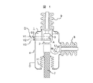
図1には、遮断機能と断路機能を備えた真空バルブ1が示されている。
【0014】
まず、真空バルブ1の構造について説明する。金属容器4の内部は密封されて真空状態となっている。接地された金属容器4の内部には対向している可動電極2と固定電極3が配置されている。固定電極3はブッシング9に接続し、ブッシング9を介して母線に接続されている。可動電極2はフレキシブル導体12を介してブッシング8に接続し、ブッシング8を介して負荷に接続されている。固定電極3に可動電極2が接触している閉状態の真空バルブ1では、固定電極3−可動電極2−フレキシブル導体12−の経路で電流が流れる。固定電極3の周囲には、遮断時にアークAが直接金属容器4に触れて地絡事故が発生するのを回避するためのアークシールド14を設けた。アークシールド14は、遮断時に電極から放出される金属粒子が飛散して、例えば絶縁ロッド7を汚すなど、絶縁性能の劣化を防ぐ役割もある。可動電極2は絶縁ロッド7と接続される。真空バルブ1と個別に設けた操作機構(図示せず)で可動電極2を絶縁ロッド7を介して上下に駆動し、固定電極3と可動電極2を開閉する。また、絶縁ロッド7はベローズ11を介して金属容器4に接続され、真空を維持しながら絶縁ロッド7を駆動できるようになっている。
【0015】
可動電極2は、電極が接触する閉位置Y1と、雷などのサージ電圧が印加されても絶縁が保証される断路位置Y3の2つの位置に停止する。例えばJEC規格2300,2310などに記載されるように、断路器の極間耐電圧は遮断器のそれに比べて高く設定されている。可動電極2が断路位置Y3に停止しているときの開極距離,電極とアークシールド14間の絶縁距離、などは断路器の耐電圧仕様で設計しなければならない。また、可動電極2が断路位置Y3に停止するときは、作業者の安全を確保する上で、万一の場合でも電極間で絶縁破壊するのではなく、接地側に放電するように絶縁協調を図る必要がある。例えば、図2に示すように、電極間の電界E3を電極2,3とアークシールド14間の電界E1,
E2に比べて小さくして、放電経路41ではなく、放電経路42−43で絶縁破壊するように構成することによって、作業者の安全が確保できる。
【0016】
次に、図3および図4を用いて、本実施例の真空開閉装置の開閉特性について説明する。図3は、開極動作における可動電極2の位置の時間変化を示す。符号Y2は、閉位置Y1と断路位置Y3の間に存在し、真空開閉装置における開位置を表す。可動電極2は、開位置Y2を通過した後の時間t0 から強制的に減速され、断路位置Y3まで移動する。図4は、閉極動作における可動電極2の位置の時間変化を示す。可動電極2は、加速しながら断路位置Y3から閉位置Y1へ移動する。
【0017】
開極時に減速を開始する時間t0 は、以下の手順で決定する。
【0018】
図5は、極間耐電圧および遮断性能と、可動電極2の位置(極間距離D)の関係を示したものである。極間耐電圧と極間距離Dの関係については、極間距離Dが増加するにつれて極間耐電圧は上昇する。一方、遮断性能と極間距離Dの関係については、極間距離がD0 の時に遮断性能は最大値を示す。極間距離DがD0 よりも大きくなると遮断性能は低下する。これは、極間距離DがD0 以上になると、極間から放出される金属粒子の絶縁物を汚す領域が増加するため遮断性能が低下するからである。
【0019】
ここで、極間距離D3 は可動電極2が断路位置Y3に停止するときの極間距離である。
【0020】
図5から、電極を遮断するには、遮断性能が高く、極間耐電圧が高い状態、すなわち斜線で示した領域(極間距離Dが0.5×D3 ≦D2 ≦0.7×D3 の範囲)にあることが好ましい。したがって、可動電極2が開位置Y2にあるときの極間距離D2 は、可動電極2が断路位置Y3に停止するときの極間距離D3 をベースにすると、0.5×D3 ≦D2 ≦0.7×D3 の範囲にあることが好ましい。
【0021】
(実施例2)
上記の開閉特性を実施するための操作機構を図6を用いて説明する。図6は、図1に示した真空バルブ1をバネ操作機構25で操作する開閉装置を示している。符号30は遮断バネ部であり、畜勢された遮断バネ31を個別に設けたトリップ機構で開放して駆動力を発生し、駆動力はシャフト22などを通じて絶縁ロッド7に伝達される。符号20はストッパを表す。ストッパ20はシャフト22の回転量を制限して可動電極2の移動距離を決定する。可動電極2が断路位置Y3に達したときにシャフト22がストッパ20に衝突するように調整する。ショックアブソーバ21はリンク部27に設けられている。ショックアブソーバ21は、可動電極2が開位置Y2に達した時に作動開始するように調整してある。
【0022】
本発明によれば、開極距離Dは遮断に好ましいD0 に保たれ、さらに自動的に遮断状態となる。つまり、遮断性能を低下させることなく、遮断と断路の一連操作が自動的にできるようになり、使い勝手が良く、かつ作業者が誤操作するおそれのない開閉装置となる。また、遮断と断路を2段階で操作していた従来の開閉装置に比べて操作機構が簡素化される。また、可動電極2が停止位置である断路位置Y3に達する前に開極速度を低下させるため、衝撃力が低減されて真空バルブ1,ベローズ7,操作機構25などの機械的寿命が向上する効果もある。さらに本実施例では、投入性能に関して下記の効果が得られる。断路位置Y3から投入を開始するため、従来の開閉装置より投入ストロークが長くなり、電極が接触する直前の投入速度が大きくなる。真空遮断器では、投入直前の微小ギャップ状態において電極間にアークが発弧し、投入後電極が溶着する問題があり、操作機構には溶着力以上の大きな引き外し力が要求された。本発明では投入速度が増加したため、アークの発弧時間、すなわち電極の溶着力が減少し、必要操作力が低減できるという効果を有する。
【0023】
(実施例3)
実施例1及び2においては、金属容器を接地した例について説明したが、本実施例のように容器を接地していない真空バルブに適用することができる。図7は、可動電極2を軸方向に駆動する真空バルブで、固定電極3,可動電極2の外周側にセラミック筒16を用いている。固定電極3と可動電極2の外周側でセラミック筒16との間には、アークシールド14が設けられており、アーク時に飛散するイオンやエレクトロンがセラミック筒16に付着して絶縁性能が劣化するのを防止している。可動電極2の導体部にはベローズ11が設けられており、このベローズ11,セラミック筒16等で囲まれた真空バルブ内は真空になっている。上記導体部は絶縁物を介して図6に示す操作機構25に接続されている。
【0024】
可動電極2は閉位置Y1と断路位置Y3の2つの位置に停止し、開位置Y2を通過した後に可動電極2の移動速度を減速させる。移動速度の調整は、図6の操作機構25のショックアブソーバ21によって行う。可動電極2が断路位置Y3に停止している時の極間耐電圧は、真空バルブ外部の対地間耐電圧より高く設定して絶縁協調を図る。
【0025】
空気操作機構など、バネ操作機構以外のもの、ショックアブソーバ,リンク部に位置センサを取り付けて、サーボ,フィードバックなどの制御系を構築しても同様の効果が実現できる。
【0026】
(実施例4)
本実施例は、容器を接地していない真空バルブに適用した例であり、可動電極2を備えた操作ブレードが主軸20を支点に回動する真空バルブを開示している。
【0027】
図8は、主軸20を支点に回動する真空バルブで、固定電極3,可動電極2の外周側にセラミック筒16を用いている。固定電極3と可動電極2の外周側でセラミック筒16との間には、アークシールド14が設けられており、アーク時に飛散するイオンやエレクトロンがセラミック筒16に付着して絶縁性能が劣化するのを防止している。可動電極2の導体部にはベローズ11が設けられており、このベローズ11,セラミック筒16等で囲まれた真空バルブ内は真空になっている。上記導体部は絶縁物を介して図6に示す操作機構25に接続されている。可動電極2は閉位置Y1と断路位置Y3の2つの位置に停止し、開位置Y2を通過した後に可動電極2の移動速度を減速させる。移動速度の調整は、図6の操作機構25のショックアブソーバ21によって行う。可動電極2が断路位置Y3に停止している時の極間耐電圧は、真空バルブ外部の接地間耐電圧より高く設定して絶縁協調を図る。
【0028】
空気操作機構など、バネ操作機構以外のもの、ショックアブソーバ,リンク部に位置センサを取り付けて、サーボ,フィードバックなどの制御系を構築しても同様の効果が実現できる。
【0029】
(実施例5)
本実施例は、図6に示したバネ操作機構25の遮断バネ部30にショックアブソーバ21の機能を持たせたものである。図9および図10に、遮断バネ部30の構造を示す。図9は、引っ張り用の遮断バネ31とその両端を固定するバネ支持金具32,33で構成される。支持金具32は、可動電極2が閉位置Y1のとき位置L1,断路位置Y3のとき位置L3に停止し、可動電極2が開位置Y2に達したとき位置L2を通過する。ここで、遮断バネ31の外側、あるいは内側に衝撃吸収用バネ34を個別に設けておき、衝撃吸収用バネ34は支持金具32が位置L2に通過した後に作動開始する。すなわち、衝撃吸収用バネ34は可動電極2が開位置Y2に達した時に作動開始するように調整してある。
【0030】
(実施例6)
図10は、遮断バネ31に圧縮バネを用いた場合である。この場合も、支持金具32が位置L2を通過したとき、衝撃吸収用バネ34が作動開始するように調整してある。このため、可動電極2が開位置Y2に達すると、衝撃吸収用バネ
34がブレーキとして働くので、開極速度を減速させることができる。本実施例の衝撃吸収用バネ34は実施例1のショックアブソーバ21を用いたときと同様の効果を有する。なお、衝撃吸収用バネ34のバネ定数を、遮断バネ31のバネ定数より大きくしておけば、減速効果が大きくなる。
【0031】
(実施例7)
図11には開極速度を低下させる機能をベローズ11に持たせる場合が開示されている。ベローズ11にバネ定数が大きい部分K1とバネ定数が小さい部分
K2を設けることにより、可動電極2が高速で移動する間はバネ定数の小さい部分K2が主に動作し、可動電極2が開位置Y2に達すると、部分K2が十分圧縮された状態となってバネ定数の大きい部分K1が動作し始めるようになる。つまり、可動電極2が開位置Y2に通過した後には、バネ定数が大きい部分K1が動作するので、開極速度が減速される。本実施例では、操作機構に従来の遮断器で使用していたものをそのまま利用できる利点がある。
【0032】
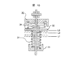
(実施例8)
図12には、遮断器と接地開閉器を集積した真空バルブが開示されている。接地された金属容器4と絶縁された固定電極3,可動電極2,接地装置15を配置し、可動電極2は閉位置Y1と接地位置Y4に停止する。可動電極2が、閉位置Y1から接地位置Y4に移動するに際して開位置Y2を通過した後に開極速度を減速させる。減速手段は、図6記載のショックアブソーバ21、図9および図
10記載の衝撃吸収用バネ34のいずれでもよい。これにより、単一の操作機構で遮断と接地の操作を自動的に連続操作できるようになる。なお、図12の真空バルブ1では、可動電極2を閉位置Y1と断路位置Y3の2つの位置に停止させて遮断と断路の機能を実現し、個別の操作機構で可動電極2と接地装置15を開閉して接地機能を実現してもよい。この場合、単一真空バルブ内に、遮断,断路,接地の3機能を集積でき、開閉装置全体が小型になる利点がある。
【0033】
【発明の効果】
本発明によれば、使い勝手が向上し、作業者の誤操作の可能性が減少した。さらに、2段階で操作していた従来の開閉装置に比べて、操作機構が簡素化,小型化できるようになった。
【図面の簡単な説明】
【図1】本発明の実施例1による真空バルブの縦断面図である。
【図2】本発明の実施例1における電極周辺の拡大図である。
【図3】本発明の実施例1における開極特性を説明するグラフである。
【図4】本発明の実施例1における開極特性を説明するグラフである。
【図5】実施例1における極間耐電圧および遮断性能と、可動電極の位置の関係を表す特性図である。
【図6】本発明の実施例2による操作機構の概略図を示す。
【図7】本発明の実施例3における真空バルブ縦断面図である。
【図8】本発明の実施例4における真空バルブの側断面図である。
【図9】本発明の実施例5による操作機構の遮断バネ部の接地断面図である。
【図10】本発明の実施例6による操作機構の遮断バネ部の接地断面図である。
【図11】本発明の実施例7による真空バルブの縦断面図である。
【図12】本発明の実施例8による真空バルブの縦断面図である。
【符号の説明】
1…真空バルブ、2…可動電極、3…固定電極、4…金属容器、7…絶縁ロッド、8,9…ブッシング、10…操作ブレード、11…ベローズ、12…フレキシブル導体、14…アークシールド、20…主軸、21…ショックアブソーバ、25…操作機構、30…遮断バネ部、31…遮断バネ、34…衝撃吸収用バネ。[0001]
TECHNICAL FIELD OF THE INVENTION
The present invention relates to a vacuum switchgear having a function of interrupting a large current.
[0002]
[Prior art]
In general, a power receiving and transforming device receives power using a circuit breaker, a disconnector, or the like, converts the power into a voltage suitable for a load using a transformer, and supplies the load with power. When performing maintenance and inspection of substation equipment, after disconnecting with a circuit breaker, open the disconnector to prevent re-application of power from the power supply side, and operate the grounding switch to operate the residual charge and induced current on the power supply side. By flowing the air to the grounding side, the safety of workers is ensured. The configuration of the power receiving / distributing equipment includes a circuit breaker, a disconnector, a grounding switch, and a current transformer in a unit room filled with insulating gas, as in a gas insulated switchgear disclosed in Japanese Patent Application Laid-Open No. 3-273804. Some are individually produced and stored. Also, as in the opening / closing device described in Japanese Patent Application Laid-Open No. 9-153320, the movable conductor 19 is moved to four positions of a closed position Y1, an open position Y2, a disconnection position Y3, and a ground position Y4, or a closed position Y1, a disconnect position Y3, and a ground position. There is also a type in which a function of stopping at the position of Y4 is provided, and three functions of a circuit breaker, a disconnector, and a grounding switch or a circuit breaker and a grounding switch are integrated in a vacuum valve.
[0003]
[Problems to be solved by the invention]
In a vacuum switchgear in which circuit breakers and disconnectors are individually arranged, the size of the device is increased. In addition, since a series of operations for shutting off and disconnecting during maintenance and inspection cannot be performed continuously, it is inconvenient to use and may be erroneously operated by an operator.
[0004]
Further, in a vacuum switching device in which a circuit breaker and a disconnecting switch are integrated in one vacuum vessel, there is a problem that an operation mechanism is complicated. Vacuum circuit breakers have an optimal opening distance to cut off large currents.If the opening distance is too large, the area where metal particles emitted from between the electrodes diffuse will increase, and the surrounding insulation will be reduced. As a result, the insulation performance of the vacuum valve is reduced. Further, since the arc length increases, the arc behavior becomes unstable, and the breaking performance may decrease. On the other hand, if the opening distance is too small, the transient recovery voltage applied between the electrodes after the disconnection cannot be maintained, and the dielectric breakdown, that is, the disconnection cannot be performed. Therefore, in the conventional switching device, the breaking operation has to be completed in a state where the movable conductor is temporarily stopped at an appropriate open position, and then the disconnection operation has to be performed individually, and as a result, the operation mechanism is complicated.
[0005]
SUMMARY OF THE INVENTION An object of the present invention is to provide a vacuum switchgear which is easy to use, has a low possibility of operator erroneous operation, and has a simpler and smaller operation mechanism than a conventional switchgear operated in two stages. It is in.
[0006]
[Means for Solving the Problems]
In order to achieve the above object, a vacuum opening and closing device of the present invention includes a fixed conductor that can be freely moved and separated in a vacuum vessel, a movable electrode, and contacting and separating means for driving the movable electrode, wherein the movable electrode is closed. In a vacuum opening / closing device that moves among three positions, a position, an open position, and a disconnection position, the movable conductor stops at two positions, a closed position and a disconnection position, and the movable electrode moves from the closed position to the open position. A speed reducing means for lowering the speed of moving from the open position to the disconnection position than the speed of the disconnection.
[0007]
The present invention includes a fixed conductor which can be freely contacted / separated in a vacuum vessel, a movable electrode, and a contact / separation means for driving the movable electrode, and the movable electrode has three positions of a closed position, an open position and a disconnection position. the mobile vacuum switchgear which satisfies 0.5 × D 3 ≦ D 2 ≦ 0.7 ×
[0008]
The present invention is a vacuum opening / closing device having a shock absorber that starts operating when a movable electrode reaches an open position as a deceleration means.
[0009]
The present invention is a vacuum switchgear having, as deceleration means, a blocking spring of a spring operating mechanism for driving the movable electrode and a shock absorbing spring that starts operating when the movable electrode reaches the open position.
[0010]
The present invention is a vacuum switching device wherein the spring constant of the spring for absorbing an impact force is larger than the spring constant of the blocking spring.
[0011]
The present invention is a vacuum opening and closing device in which a movable electrode is fixed to a vacuum vessel via a bellows as a deceleration means, and a bellows is formed so that a spring constant increases when the movable electrode reaches an open position.
[0012]
BEST MODE FOR CARRYING OUT THE INVENTION
An embodiment of the present invention will be described with reference to FIGS.
[0013]
(Example 1)
FIG. 1 shows a vacuum valve 1 having a shutoff function and a disconnection function.
[0014]
First, the structure of the vacuum valve 1 will be described. The inside of the
[0015]
The
By making it smaller than E2 so as to cause dielectric breakdown in the discharge path 42-43 instead of the
[0016]
Next, the opening / closing characteristics of the vacuum opening / closing device of this embodiment will be described with reference to FIGS. FIG. 3 shows a time change of the position of the
[0017]
Time t 0 to start the deceleration at the time of opening is determined by the following procedure.
[0018]
FIG. 5 shows the relationship between the inter-electrode withstand voltage and interception performance and the position of the movable electrode 2 (inter-electrode distance D). Regarding the relationship between the inter-electrode withstand voltage and the inter-electrode distance D, the inter-electrode withstand voltage increases as the inter-electrode distance D increases. On the other hand, the relationship between the cut-off performance and inter-electrode distance D, interruption performance inter-electrode distance when D 0 is a maximum value. When the inter-electrode distance D becomes larger than D 0 , the blocking performance decreases. This is because, when the inter-electrode distance D is equal to or more than D 0 , the area where the metal particles emitted from the inter-electrode contaminate the insulator increases, so that the blocking performance decreases.
[0019]
Here, inter-electrode distance D 3 is the distance between the electrodes when the
[0020]
From FIG. 5, in order to cut off the electrodes, the cutoff performance is high and the withstand voltage between the electrodes is high, that is, the region indicated by oblique lines (the gap between the electrodes D is 0.5 × D 3 ≦ D 2 ≦ 0.7 × it is preferably in the D range 3). Therefore, inter-electrode distance D 2 at the time when the
[0021]
(Example 2)
An operation mechanism for implementing the above opening and closing characteristics will be described with reference to FIG. FIG. 6 shows an opening and closing device for operating the vacuum valve 1 shown in FIG.
[0022]
According to the present invention, opening distance D is maintained at the preferred D 0 to the cutoff, further comprising automatically cut off. That is, a series of operations of shutting off and disconnecting can be automatically performed without lowering the shutoff performance, so that the opening / closing device is easy to use and has no risk of erroneous operation by the operator. Further, the operation mechanism is simplified as compared with a conventional opening / closing device in which shutoff and disconnection are operated in two stages. Further, since the opening speed is reduced before the
[0023]
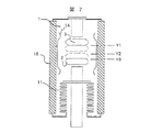
(Example 3)
In the first and second embodiments, the example in which the metal container is grounded has been described. However, the present invention can be applied to a vacuum valve in which the container is not grounded as in the present embodiment. FIG. 7 shows a vacuum valve for driving the
[0024]
The
[0025]
Similar effects can be achieved by constructing a control system such as a servo or feedback by attaching a position sensor to a mechanism other than the spring operating mechanism such as a pneumatic operating mechanism, a shock absorber, and a link.
[0026]
(Example 4)
This embodiment is an example in which the container is applied to a vacuum valve in which the container is not grounded, and discloses a vacuum valve in which an operation blade provided with a
[0027]
FIG. 8 shows a vacuum valve that rotates around a
[0028]
Similar effects can be achieved by constructing a control system such as a servo or feedback by attaching a position sensor to a mechanism other than the spring operating mechanism such as a pneumatic operating mechanism, a shock absorber, and a link.
[0029]
(Example 5)
In this embodiment, the function of the
[0030]
(Example 6)
FIG. 10 shows a case where a compression spring is used as the blocking
[0031]
(Example 7)
FIG. 11 discloses a case where the
[0032]
(Example 8)
FIG. 12 discloses a vacuum valve in which a circuit breaker and a ground switch are integrated. The fixed
[0033]
【The invention's effect】
ADVANTAGE OF THE INVENTION According to this invention, usability | operativity improved and the possibility of the operator's erroneous operation decreased. Further, the operation mechanism can be simplified and downsized as compared with the conventional switchgear operated in two stages.
[Brief description of the drawings]
FIG. 1 is a longitudinal sectional view of a vacuum valve according to Embodiment 1 of the present invention.
FIG. 2 is an enlarged view around an electrode according to the first embodiment of the present invention.
FIG. 3 is a graph illustrating opening characteristics in Example 1 of the present invention.
FIG. 4 is a graph illustrating opening characteristics in Example 1 of the present invention.
FIG. 5 is a characteristic diagram illustrating a relationship between a withstand voltage between electrodes and a breaking performance and a position of a movable electrode in the first embodiment.
FIG. 6 shows a schematic diagram of an operation mechanism according to
FIG. 7 is a vertical sectional view of a vacuum valve according to a third embodiment of the present invention.
FIG. 8 is a side sectional view of a vacuum valve according to a fourth embodiment of the present invention.
FIG. 9 is a ground cross-sectional view of a cut-off spring portion of an operation mechanism according to a fifth embodiment of the present invention.
FIG. 10 is a ground cross-sectional view of a blocking spring portion of an operation mechanism according to a sixth embodiment of the present invention.
FIG. 11 is a longitudinal sectional view of a vacuum valve according to
FIG. 12 is a longitudinal sectional view of a vacuum valve according to
[Explanation of symbols]
DESCRIPTION OF SYMBOLS 1 ... Vacuum valve, 2 ... movable electrode, 3 ... fixed electrode, 4 ... metal container, 7 ... insulating rod, 8, 9 ... bushing, 10 ... operating blade, 11 ... bellows, 12 ... flexible conductor, 14 ... arc shield, Reference numeral 20: main shaft, 21: shock absorber, 25: operating mechanism, 30: cut-off spring portion, 31: cut-off spring, 34: shock absorbing spring.
Claims (7)
前記可動電極の開位置が閉位置と断路位置の間にあり、かつ、該可動電極が前記閉位置と断路位置の2つの位置に停止し、該可動電極が前記閉位置から開位置に移動する速度よりも前記開位置から断路位置に移動する速度を低下させ、遮断と断路の一連の操作を自動的に行うことを特徴とする真空開閉装置の開閉方法。A fixed electrode and a movable electrode provided in a vacuum vessel are opened and closed by opening and closing means, the movable electrode is closed, an open position for cutting off a large current, and a disconnection position where insulation is ensured even when a surge voltage is applied. In the opening and closing method of the vacuum opening and closing device for moving the three positions,
The open position of the movable electrode is between the closed position and the disconnection position, and the movable electrode stops at two positions of the closed position and the disconnection position, and the movable electrode moves from the closed position to the open position. A method for opening and closing a vacuum opening and closing device, wherein a speed of moving from the open position to the disconnection position is lower than a speed, and a series of operations of shutting off and disconnection are automatically performed .
前記可動電極の開位置が閉位置と断路位置の間にあり、かつ、該可動電極が前記閉位置と断路位置の2つの位置に停止し、前記可動電極が前記閉位置から開位置に移動する速度よりも前記開位置から断路位置に移動する速度を低下させる減速手段を備え、遮断と断路の一連の操作が自動的に行えることを特徴とする真空開閉装置。A fixed electrode and a movable electrode provided in a vacuum vessel, and an opening / closing means for opening and closing the fixed electrode and the movable electrode, wherein the movable electrode is closed by the opening / closing means, an open position for interrupting a large current , In a vacuum switchgear that moves between three disconnection positions where insulation is guaranteed even when a surge voltage is applied ,
The open position of the movable electrode is between the closed position and the disconnection position, and the movable electrode stops at two positions of the closed position and the disconnection position, and the movable electrode moves from the closed position to the open position. A vacuum opening and closing device comprising a speed reducing means for lowering a speed of moving from the open position to a disconnection position than a speed , and a series of operations of shutoff and disconnection can be automatically performed .
Priority Applications (7)
| Application Number | Priority Date | Filing Date | Title |
|---|---|---|---|
| JP01521799A JP3589061B2 (en) | 1999-01-25 | 1999-01-25 | Vacuum switchgear and method for opening and closing vacuum switchgear |
| DE69931744T DE69931744T2 (en) | 1999-01-25 | 1999-03-02 | Vacuum switchgear |
| EP99104185A EP1022761B1 (en) | 1999-01-25 | 1999-03-02 | Vacuum switching apparatus |
| US09/268,679 US6107592A (en) | 1999-01-25 | 1999-03-16 | Vacuum switching apparatus |
| KR1019990009132A KR100587575B1 (en) | 1999-01-25 | 1999-03-18 | Vacuum switching device and method thereof |
| CNB991041364A CN1149601C (en) | 1999-01-25 | 1999-03-19 | Vacuum switch apparatus |
| CNB200410006753XA CN1331177C (en) | 1999-01-25 | 1999-03-19 | Vacuum switching apparatus |
Applications Claiming Priority (1)
| Application Number | Priority Date | Filing Date | Title |
|---|---|---|---|
| JP01521799A JP3589061B2 (en) | 1999-01-25 | 1999-01-25 | Vacuum switchgear and method for opening and closing vacuum switchgear |
Publications (3)
| Publication Number | Publication Date |
|---|---|
| JP2000215768A JP2000215768A (en) | 2000-08-04 |
| JP2000215768A5 JP2000215768A5 (en) | 2004-07-29 |
| JP3589061B2 true JP3589061B2 (en) | 2004-11-17 |
Family
ID=11882719
Family Applications (1)
| Application Number | Title | Priority Date | Filing Date |
|---|---|---|---|
| JP01521799A Expired - Lifetime JP3589061B2 (en) | 1999-01-25 | 1999-01-25 | Vacuum switchgear and method for opening and closing vacuum switchgear |
Country Status (6)
| Country | Link |
|---|---|
| US (1) | US6107592A (en) |
| EP (1) | EP1022761B1 (en) |
| JP (1) | JP3589061B2 (en) |
| KR (1) | KR100587575B1 (en) |
| CN (2) | CN1149601C (en) |
| DE (1) | DE69931744T2 (en) |
Families Citing this family (18)
| Publication number | Priority date | Publication date | Assignee | Title |
|---|---|---|---|---|
| US6362445B1 (en) * | 2000-01-03 | 2002-03-26 | Eaton Corporation | Modular, miniaturized switchgear |
| DE10104392C2 (en) * | 2001-01-19 | 2003-07-03 | Siemens Ag | Vacuum switch and system and method for its control |
| US7473863B2 (en) * | 2003-02-06 | 2009-01-06 | Cooper Technologies Company | High voltage operating rod sensor and method of making the same |
| JP4174495B2 (en) * | 2005-06-29 | 2008-10-29 | 株式会社日立製作所 | Switchgear switchgear |
| DE102006015308A1 (en) * | 2006-03-29 | 2007-10-11 | Siemens Ag | Insulating shift rod |
| JP5005512B2 (en) * | 2007-11-07 | 2012-08-22 | 東京エレクトロン株式会社 | A gate valve device, a vacuum processing device, and a method for opening a valve body in the gate valve device. |
| EP2075817A1 (en) * | 2007-12-27 | 2009-07-01 | Ormazabal Y Cia., S.A. | Actuation transmission system for electrical equipment |
| CN101807489A (en) * | 2010-03-21 | 2010-08-18 | 黄勤飞 | Three-station switching tube |
| CN102420072B (en) * | 2011-08-12 | 2015-04-15 | 王永法 | Three-phase co-chamber vacuum extinction chamber |
| US9177742B2 (en) | 2011-10-18 | 2015-11-03 | G & W Electric Company | Modular solid dielectric switchgear |
| US10276318B1 (en) | 2013-03-15 | 2019-04-30 | Innovative Switchgear IP, LLC | Insulated switch |
| CN104517776B (en) * | 2013-09-27 | 2017-10-03 | 北京电研华源电力技术有限公司 | A kind of station vacuum interrupter of disconnecting switch three |
| KR101689180B1 (en) * | 2014-12-31 | 2016-12-23 | 주식회사 효성 | Vacuum interrupter and operating method thereof |
| JP6214844B2 (en) * | 2015-08-31 | 2017-10-18 | 三菱電機株式会社 | Opening speed adjustment mechanism and switchgear |
| CN105216002B (en) * | 2015-11-02 | 2017-12-08 | 国网安徽省电力公司合肥供电公司 | High-altitude robotic gripper arm device and its anti-induced electrical structure |
| GB2562069B (en) * | 2017-05-03 | 2020-05-20 | Tavrida Electric Holding Ag | Improved vacuum circuit breaker |
| EP3503150B1 (en) * | 2017-12-21 | 2024-02-14 | ABB Schweiz AG | Method for operating the drive of a vacuum interrupter, and vacuum interrupter itself |
| US20230386770A1 (en) * | 2020-10-06 | 2023-11-30 | Mitsubishi Electric Corporation | Switch |
Family Cites Families (12)
| Publication number | Priority date | Publication date | Assignee | Title |
|---|---|---|---|---|
| US4079217A (en) * | 1976-07-26 | 1978-03-14 | International Telephone And Telegraph Corporation | Vacuum interrupter with bellows dampener |
| US4225763A (en) * | 1978-03-23 | 1980-09-30 | General Electric Company | Means for suppressing contact-separation at the end of a vacuum circuit-breaker closing operation |
| JPS6065955A (en) * | 1983-09-17 | 1985-04-15 | Mitsubishi Electric Corp | Bellows |
| DK0385265T3 (en) * | 1989-03-03 | 1994-11-14 | Gec Alsthom T & D Ag | Spring power drive for a circuit breaker |
| FR2711269B1 (en) * | 1993-10-12 | 1995-12-29 | Gec Alsthom T & D Sa | High voltage circuit breaker capable of breaking delayed zero crossing fault currents. |
| US5747766A (en) * | 1993-03-16 | 1998-05-05 | Cooper Industries, Inc. | Operating mechanism usable with a vacuum interrupter |
| TW389919B (en) * | 1995-09-27 | 2000-05-11 | Hitachi Ltd | Insulated type switching device |
| JP2948154B2 (en) * | 1995-09-27 | 1999-09-13 | 株式会社日立製作所 | Insulated switchgear |
| DE19540777A1 (en) * | 1995-11-02 | 1997-05-07 | Asea Brown Boveri | Electrical switching device |
| DE19631533A1 (en) * | 1996-07-24 | 1998-01-29 | Siemens Ag | Load switchgear for HV disconnection of power distribution transformer |
| JP3431439B2 (en) * | 1997-03-06 | 2003-07-28 | 株式会社日立製作所 | Insulated switchgear |
| JP3462367B2 (en) * | 1997-06-27 | 2003-11-05 | 株式会社日立製作所 | Composite insulated switchgear |
-
1999
- 1999-01-25 JP JP01521799A patent/JP3589061B2/en not_active Expired - Lifetime
- 1999-03-02 DE DE69931744T patent/DE69931744T2/en not_active Expired - Lifetime
- 1999-03-02 EP EP99104185A patent/EP1022761B1/en not_active Revoked
- 1999-03-16 US US09/268,679 patent/US6107592A/en not_active Expired - Lifetime
- 1999-03-18 KR KR1019990009132A patent/KR100587575B1/en not_active IP Right Cessation
- 1999-03-19 CN CNB991041364A patent/CN1149601C/en not_active Expired - Fee Related
- 1999-03-19 CN CNB200410006753XA patent/CN1331177C/en not_active Expired - Fee Related
Also Published As
| Publication number | Publication date |
|---|---|
| CN1547229A (en) | 2004-11-17 |
| US6107592A (en) | 2000-08-22 |
| KR100587575B1 (en) | 2006-06-08 |
| KR20000052273A (en) | 2000-08-16 |
| CN1262521A (en) | 2000-08-09 |
| CN1331177C (en) | 2007-08-08 |
| JP2000215768A (en) | 2000-08-04 |
| DE69931744T2 (en) | 2007-05-31 |
| EP1022761A3 (en) | 2002-11-13 |
| CN1149601C (en) | 2004-05-12 |
| DE69931744D1 (en) | 2006-07-20 |
| EP1022761B1 (en) | 2006-06-07 |
| EP1022761A2 (en) | 2000-07-26 |
Similar Documents
| Publication | Publication Date | Title |
|---|---|---|
| JP3589061B2 (en) | Vacuum switchgear and method for opening and closing vacuum switchgear | |
| US7986061B2 (en) | Electrical switching device | |
| JP3431439B2 (en) | Insulated switchgear | |
| JPH06310000A (en) | Grounding switch | |
| JPH11265646A (en) | Insulating switching device | |
| KR20170046300A (en) | High speed switch using supercritical fluid and current interrupt appratus using it and current interrupt method | |
| JP3369228B2 (en) | High-speed reclosable earthing switch | |
| KR100344281B1 (en) | Bidirectional operation type gas circuit breaker | |
| JPH03251005A (en) | Line breaker for vehicle | |
| JP3369224B2 (en) | High-speed reclosable earthing switch | |
| JP3175704B2 (en) | Insulated switchgear | |
| JPH0520984A (en) | Resistance interrupting type circuit breaker | |
| JP2523478B2 (en) | Puffer type gas breaker | |
| JP3175701B2 (en) | Insulated switchgear | |
| JP3175702B2 (en) | Insulated switchgear | |
| JPH06310001A (en) | High speed grounding switch | |
| JP3369221B2 (en) | Puffer type gas circuit breaker with resistance | |
| JPH0334228A (en) | Vacuum circuit breaker | |
| JPH06124627A (en) | High speed re-closing path earthed switch | |
| JPH11317135A (en) | Insulated switch device | |
| JPH08321234A (en) | High speed grounding switch | |
| JPH03219513A (en) | Vacuum-type circuit breaker | |
| JPH07105800A (en) | High speed reclosing and grounding switch | |
| JPH0992099A (en) | High-speed earth switch | |
| JPH09161622A (en) | Circuit breaker |
Legal Events
| Date | Code | Title | Description |
|---|---|---|---|
| A131 | Notification of reasons for refusal |
Free format text: JAPANESE INTERMEDIATE CODE: A131 Effective date: 20040106 |
|
| A521 | Written amendment |
Free format text: JAPANESE INTERMEDIATE CODE: A523 Effective date: 20040308 |
|
| TRDD | Decision of grant or rejection written | ||
| A01 | Written decision to grant a patent or to grant a registration (utility model) |
Free format text: JAPANESE INTERMEDIATE CODE: A01 Effective date: 20040727 |
|
| A61 | First payment of annual fees (during grant procedure) |
Free format text: JAPANESE INTERMEDIATE CODE: A61 Effective date: 20040809 |
|
| FPAY | Renewal fee payment (event date is renewal date of database) |
Free format text: PAYMENT UNTIL: 20070827 Year of fee payment: 3 |
|
| FPAY | Renewal fee payment (event date is renewal date of database) |
Free format text: PAYMENT UNTIL: 20080827 Year of fee payment: 4 |
|
| FPAY | Renewal fee payment (event date is renewal date of database) |
Free format text: PAYMENT UNTIL: 20080827 Year of fee payment: 4 |
|
| FPAY | Renewal fee payment (event date is renewal date of database) |
Free format text: PAYMENT UNTIL: 20090827 Year of fee payment: 5 |
|
| FPAY | Renewal fee payment (event date is renewal date of database) |
Free format text: PAYMENT UNTIL: 20100827 Year of fee payment: 6 |
|
| FPAY | Renewal fee payment (event date is renewal date of database) |
Free format text: PAYMENT UNTIL: 20100827 Year of fee payment: 6 |
|
| FPAY | Renewal fee payment (event date is renewal date of database) |
Free format text: PAYMENT UNTIL: 20110827 Year of fee payment: 7 |
|
| FPAY | Renewal fee payment (event date is renewal date of database) |
Free format text: PAYMENT UNTIL: 20120827 Year of fee payment: 8 |
|
| FPAY | Renewal fee payment (event date is renewal date of database) |
Free format text: PAYMENT UNTIL: 20130827 Year of fee payment: 9 |
|
| S111 | Request for change of ownership or part of ownership |
Free format text: JAPANESE INTERMEDIATE CODE: R313111 |
|
| S531 | Written request for registration of change of domicile |
Free format text: JAPANESE INTERMEDIATE CODE: R313531 |
|
| R350 | Written notification of registration of transfer |
Free format text: JAPANESE INTERMEDIATE CODE: R350 |
|
| EXPY | Cancellation because of completion of term |