EP3503035B1 - Three dimensional virtual and augmented reality display system - Google Patents
Three dimensional virtual and augmented reality display system Download PDFInfo
- Publication number
- EP3503035B1 EP3503035B1 EP19154686.0A EP19154686A EP3503035B1 EP 3503035 B1 EP3503035 B1 EP 3503035B1 EP 19154686 A EP19154686 A EP 19154686A EP 3503035 B1 EP3503035 B1 EP 3503035B1
- Authority
- EP
- European Patent Office
- Prior art keywords
- eye
- image
- diffraction
- viewer
- mode
- Prior art date
- Legal status (The legal status is an assumption and is not a legal conclusion. Google has not performed a legal analysis and makes no representation as to the accuracy of the status listed.)
- Active
Links
- 230000003190 augmentative effect Effects 0.000 title description 11
- 238000000059 patterning Methods 0.000 claims description 14
- 230000000007 visual effect Effects 0.000 claims description 12
- 210000001747 pupil Anatomy 0.000 claims description 6
- 239000004973 liquid crystal related substance Substances 0.000 claims description 3
- 238000012800 visualization Methods 0.000 claims description 3
- 230000002596 correlated effect Effects 0.000 claims description 2
- 239000000758 substrate Substances 0.000 claims description 2
- 238000003384 imaging method Methods 0.000 description 11
- 230000004308 accommodation Effects 0.000 description 10
- 238000000034 method Methods 0.000 description 9
- 230000008447 perception Effects 0.000 description 7
- 210000004556 brain Anatomy 0.000 description 4
- 230000006870 function Effects 0.000 description 3
- 230000002350 accommodative effect Effects 0.000 description 2
- 230000000903 blocking effect Effects 0.000 description 2
- 230000000875 corresponding effect Effects 0.000 description 2
- 210000000695 crystalline len Anatomy 0.000 description 2
- 230000003247 decreasing effect Effects 0.000 description 2
- 230000000694 effects Effects 0.000 description 2
- 238000005516 engineering process Methods 0.000 description 2
- 238000001914 filtration Methods 0.000 description 2
- 210000003128 head Anatomy 0.000 description 2
- 230000000873 masking effect Effects 0.000 description 2
- 239000000463 material Substances 0.000 description 2
- 230000007246 mechanism Effects 0.000 description 2
- 238000012986 modification Methods 0.000 description 2
- 230000004048 modification Effects 0.000 description 2
- 230000008569 process Effects 0.000 description 2
- 230000004044 response Effects 0.000 description 2
- 230000035807 sensation Effects 0.000 description 2
- 206010019233 Headaches Diseases 0.000 description 1
- 238000013459 approach Methods 0.000 description 1
- 208000003464 asthenopia Diseases 0.000 description 1
- 230000000740 bleeding effect Effects 0.000 description 1
- 230000009977 dual effect Effects 0.000 description 1
- 239000011521 glass Substances 0.000 description 1
- 231100000869 headache Toxicity 0.000 description 1
- 230000008676 import Effects 0.000 description 1
- 230000002452 interceptive effect Effects 0.000 description 1
- 239000007788 liquid Substances 0.000 description 1
- 238000004519 manufacturing process Methods 0.000 description 1
- 239000000203 mixture Substances 0.000 description 1
- 238000012545 processing Methods 0.000 description 1
- 238000012552 review Methods 0.000 description 1
- 238000000926 separation method Methods 0.000 description 1
- 238000004088 simulation Methods 0.000 description 1
- 238000010408 sweeping Methods 0.000 description 1
Images


Classifications
-
- H—ELECTRICITY
- H04—ELECTRIC COMMUNICATION TECHNIQUE
- H04N—PICTORIAL COMMUNICATION, e.g. TELEVISION
- H04N13/00—Stereoscopic video systems; Multi-view video systems; Details thereof
- H04N13/30—Image reproducers
- H04N13/388—Volumetric displays, i.e. systems where the image is built up from picture elements distributed through a volume
- H04N13/39—Volumetric displays, i.e. systems where the image is built up from picture elements distributed through a volume the picture elements emitting light at places where a pair of light beams intersect in a transparent material
-
- G—PHYSICS
- G02—OPTICS
- G02B—OPTICAL ELEMENTS, SYSTEMS OR APPARATUS
- G02B27/00—Optical systems or apparatus not provided for by any of the groups G02B1/00 - G02B26/00, G02B30/00
- G02B27/01—Head-up displays
- G02B27/0101—Head-up displays characterised by optical features
-
- G—PHYSICS
- G02—OPTICS
- G02B—OPTICAL ELEMENTS, SYSTEMS OR APPARATUS
- G02B30/00—Optical systems or apparatus for producing three-dimensional [3D] effects, e.g. stereoscopic images
- G02B30/20—Optical systems or apparatus for producing three-dimensional [3D] effects, e.g. stereoscopic images by providing first and second parallax images to an observer's left and right eyes
- G02B30/22—Optical systems or apparatus for producing three-dimensional [3D] effects, e.g. stereoscopic images by providing first and second parallax images to an observer's left and right eyes of the stereoscopic type
- G02B30/24—Optical systems or apparatus for producing three-dimensional [3D] effects, e.g. stereoscopic images by providing first and second parallax images to an observer's left and right eyes of the stereoscopic type involving temporal multiplexing, e.g. using sequentially activated left and right shutters
-
- G—PHYSICS
- G02—OPTICS
- G02B—OPTICAL ELEMENTS, SYSTEMS OR APPARATUS
- G02B30/00—Optical systems or apparatus for producing three-dimensional [3D] effects, e.g. stereoscopic images
- G02B30/20—Optical systems or apparatus for producing three-dimensional [3D] effects, e.g. stereoscopic images by providing first and second parallax images to an observer's left and right eyes
- G02B30/34—Stereoscopes providing a stereoscopic pair of separated images corresponding to parallactically displaced views of the same object, e.g. 3D slide viewers
-
- G—PHYSICS
- G02—OPTICS
- G02B—OPTICAL ELEMENTS, SYSTEMS OR APPARATUS
- G02B30/00—Optical systems or apparatus for producing three-dimensional [3D] effects, e.g. stereoscopic images
- G02B30/50—Optical systems or apparatus for producing three-dimensional [3D] effects, e.g. stereoscopic images the image being built up from image elements distributed over a 3D volume, e.g. voxels
- G02B30/52—Optical systems or apparatus for producing three-dimensional [3D] effects, e.g. stereoscopic images the image being built up from image elements distributed over a 3D volume, e.g. voxels the 3D volume being constructed from a stack or sequence of 2D planes, e.g. depth sampling systems
-
- G—PHYSICS
- G02—OPTICS
- G02B—OPTICAL ELEMENTS, SYSTEMS OR APPARATUS
- G02B5/00—Optical elements other than lenses
- G02B5/18—Diffraction gratings
- G02B5/1876—Diffractive Fresnel lenses; Zone plates; Kinoforms
-
- G—PHYSICS
- G03—PHOTOGRAPHY; CINEMATOGRAPHY; ANALOGOUS TECHNIQUES USING WAVES OTHER THAN OPTICAL WAVES; ELECTROGRAPHY; HOLOGRAPHY
- G03B—APPARATUS OR ARRANGEMENTS FOR TAKING PHOTOGRAPHS OR FOR PROJECTING OR VIEWING THEM; APPARATUS OR ARRANGEMENTS EMPLOYING ANALOGOUS TECHNIQUES USING WAVES OTHER THAN OPTICAL WAVES; ACCESSORIES THEREFOR
- G03B21/00—Projectors or projection-type viewers; Accessories therefor
-
- G—PHYSICS
- G03—PHOTOGRAPHY; CINEMATOGRAPHY; ANALOGOUS TECHNIQUES USING WAVES OTHER THAN OPTICAL WAVES; ELECTROGRAPHY; HOLOGRAPHY
- G03B—APPARATUS OR ARRANGEMENTS FOR TAKING PHOTOGRAPHS OR FOR PROJECTING OR VIEWING THEM; APPARATUS OR ARRANGEMENTS EMPLOYING ANALOGOUS TECHNIQUES USING WAVES OTHER THAN OPTICAL WAVES; ACCESSORIES THEREFOR
- G03B35/00—Stereoscopic photography
- G03B35/08—Stereoscopic photography by simultaneous recording
-
- G—PHYSICS
- G03—PHOTOGRAPHY; CINEMATOGRAPHY; ANALOGOUS TECHNIQUES USING WAVES OTHER THAN OPTICAL WAVES; ELECTROGRAPHY; HOLOGRAPHY
- G03B—APPARATUS OR ARRANGEMENTS FOR TAKING PHOTOGRAPHS OR FOR PROJECTING OR VIEWING THEM; APPARATUS OR ARRANGEMENTS EMPLOYING ANALOGOUS TECHNIQUES USING WAVES OTHER THAN OPTICAL WAVES; ACCESSORIES THEREFOR
- G03B35/00—Stereoscopic photography
- G03B35/18—Stereoscopic photography by simultaneous viewing
-
- G—PHYSICS
- G06—COMPUTING; CALCULATING OR COUNTING
- G06T—IMAGE DATA PROCESSING OR GENERATION, IN GENERAL
- G06T19/00—Manipulating 3D models or images for computer graphics
- G06T19/006—Mixed reality
-
- H—ELECTRICITY
- H04—ELECTRIC COMMUNICATION TECHNIQUE
- H04N—PICTORIAL COMMUNICATION, e.g. TELEVISION
- H04N13/00—Stereoscopic video systems; Multi-view video systems; Details thereof
- H04N13/30—Image reproducers
- H04N13/302—Image reproducers for viewing without the aid of special glasses, i.e. using autostereoscopic displays
- H04N13/322—Image reproducers for viewing without the aid of special glasses, i.e. using autostereoscopic displays using varifocal lenses or mirrors
-
- H—ELECTRICITY
- H04—ELECTRIC COMMUNICATION TECHNIQUE
- H04N—PICTORIAL COMMUNICATION, e.g. TELEVISION
- H04N13/00—Stereoscopic video systems; Multi-view video systems; Details thereof
- H04N13/30—Image reproducers
- H04N13/388—Volumetric displays, i.e. systems where the image is built up from picture elements distributed through a volume
- H04N13/395—Volumetric displays, i.e. systems where the image is built up from picture elements distributed through a volume with depth sampling, i.e. the volume being constructed from a stack or sequence of 2D image planes
-
- G—PHYSICS
- G02—OPTICS
- G02B—OPTICAL ELEMENTS, SYSTEMS OR APPARATUS
- G02B27/00—Optical systems or apparatus not provided for by any of the groups G02B1/00 - G02B26/00, G02B30/00
- G02B27/01—Head-up displays
- G02B27/0101—Head-up displays characterised by optical features
- G02B2027/0132—Head-up displays characterised by optical features comprising binocular systems
- G02B2027/0134—Head-up displays characterised by optical features comprising binocular systems of stereoscopic type
-
- G—PHYSICS
- G02—OPTICS
- G02B—OPTICAL ELEMENTS, SYSTEMS OR APPARATUS
- G02B5/00—Optical elements other than lenses
- G02B5/18—Diffraction gratings
- G02B5/1828—Diffraction gratings having means for producing variable diffraction
Definitions
- the present invention relates to virtual reality and augmented reality imaging and visualization systems.
- each point in the display's visual field it is desirable for each point in the display's visual field to generate the accommodative response corresponding to its virtual depth. If the accommodative response to a display point does not correspond to the virtual depth of that point, as determined by the binocular depth cues of convergence and stereopsis, the human eye may experience an accommodation conflict, resulting in unstable imaging, harmful eye strain, headaches, and, in the absence of accommodation information, almost a complete lack of surface depth.
- an augmented reality scenario (8) is depicted with views to the user of actual objects within the user's reality, such as landscaping items including a concrete stage object (1120) in a park setting, and also views of virtual objects added into the view to produce the "augmented" reality view; here a robot statue (1110) is shown virtually standing upon the stage object (1120), and a bee character (2) is shown flying in the airspace near the user's head.
- the augmented reality system is 3-D capable, in which case it provides the user with the perception that the statue (1110) is standing on the stage (1120) , and that the bee character (2) is flying close to the user's head.
- This perception may be greatly enhanced by utilizing visual accommodation cues to the user's eye and brain that the virtual objects (2, 1110) have different depths of focus, and that the depth of focus or focal radii for the robot statue (1110) is approximately the same as that for the stage (1120) .
- Conventional stereoscopic 3-D simulation display systems such as that depicted in Figure 2 , typically have two displays (74, 76), one for each eye, at a fixed radial focal distance (10) .
- this conventional technology misses many of the valuable cues utilized by the human eye and brain to detect and interpret depth in three dimensions, including the accommodation cue, which is associated with the eye's repositioning of the crystalline lens within the eye complex to reach a different depth of focus with the eye.
- There is a need for an accommodation accurate display system which takes into account the accommodation aspects of the human eye/brain image processing complex.
- Patent document US 2010/157433 A1 discloses a head-mounted display comprising both image display and image generation devices. Several designs of head-mounted displays having a form mfactor similar to conventional glasses are discussed herin.
- Patent document US 2010/149611 A1 discloses a method and device for reconstructing a three-dimensional scene in a holographic display.
- the present invention relates to a system as defined in claim 1.
- One embodiment is directed to a three-dimensional image visualization system, comprising a selectively transparent projection device for projecting an image toward an eye of a viewer from a projection device position in space relative to the eye of the viewer, the projection device being capable of assuming a substantially transparent state when no image is projected; an occlusion mask device coupled to the projection device and configured to selectively block light traveling toward the eye from one or more positions opposite of the projection device from the eye of the viewer in an occluding pattern correlated with the image projected by the projection device; and a zone plate diffraction patterning device interposed between the eye of the viewer and the projection device and configured to cause light from the projection device to pass through a diffraction pattern having a selectable geometry as it travels to the eye and enter the eye with a simulated focal distance from the eye based at least in part upon the selectable geometry of the diffraction pattern.
- the system further may comprise a controller operatively coupled to the projection device, occlusion mask device, and the zone plate diffraction patterning device and configured to coordinate projection of the image and associated occluding pattern, as well as interposition of the diffraction pattern at the selectable geometry.
- the controller may comprise a microprocessor.
- the projection device may comprise a substantially planar transparent digital display substantially occupying a display plane.
- the display plane may be oriented substantially perpendicularly from a visual axis of the eye of the viewer.
- the substantially planar transparent digital display may comprise a liquid crystal display.
- the substantially planar transparent digital display may comprise an organic light emitting diode display.
- the projection device may be configured to project the image toward the eye in a collimated form such that the depth of focus for the eye of the viewer is an infinite depth of focus.
- the projection device may comprise a high-speed mini-projector coupled to a substrate- guided delay exit pupil expander device configured to expand the size of the image before delivery to the eye of the viewer.
- the mini -projector may be mounted substantially perpendicularly to a visual axis of the eye of the viewer, and wherein the substrate- guided delay exit pupil expander device is configured to receive the image from the mini -proj ector and deliver it to the zone plate diffraction patterning device and to the eye of the viewer in the expanded size with an orientation substantially aligned with the visual axis of the eye.
- the zone plate diffraction patterning device and projection device may comprise at least one common structure.
- the zone plate diffraction patterning device may be integrated into a waveguide, such that the projection device comprises a high-speed mini-projector coupled to the waveguide and configured pass the image through the diffraction pattern before the image exits the waveguide en route to the eye of the viewer.
- the mini -proj ector may be mounted substantially perpendicularly to a visual axis of the eye of the viewer, and the waveguide may be configured to receive the image from the mini -proj ector and deliver it to the eye of the viewer in an expanded size with an orientation substantially aligned with the visual axis of the eye.
- the occlusion mask device my comprise a display configured to either occlude or pass light at each of a plurality of portions of the display, depending upon a pertinent command to occlude or pass light at each portion.
- the occlusion mask device may comprise one or more liquid crystal displays.
- the zone plate diffraction patterning device may comprise a high-frequency binary display configured to either occlude or pass light at each of a plurality of portions of the display, depending upon a pertinent command to occlude or pass light at each portion.
- the zone plate diffraction patterning device may have a refresh rate of between about 500Hz and about 2,000Hz.
- the zone plate diffraction patterning device may have a refresh rate of about 720Hz.
- the controller may be configured to operate the projection device and occlusion mask device at between about 30 and about 60 frames per second, and to operate the zone plate diffraction patterning device to digitally display up to about 12 different diffraction patterns for each frame of the projection device and occlusion mask device.
- the projection device, occlusion mask device, and the zone plate diffraction patterning device collectively may comprise an imaging module for a single eye of the viewer, and the system further may comprise a second imaging module for another eye of the viewer.
- FIG. 3A a simple illustration shows that in the place of two conventional displays as in stereoscopy ( Figure 2 ), two complex images, one for each eye, with various radial focal depths (12) for various aspects (14) of each image may be utilized to provide each eye with the perception of three dimensional depth layering within the perceived image.
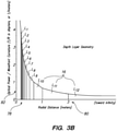
- FIG. 3B we have determined that the typical human eye is able to interpret approximately 12 layers (layers L1-L12 in Figure 3B - drawing element 16) of depth based upon radial distance.
- a near field limit (78) of about 0.25 meters is about the closest depth of focus;
- a far-field limit (80) of about 3 meters means that any item farther than about 3 meters from the human eye receives infinite focus.
- the layers of focus get more and more thin as one gets closer to the eye; in other words, the eye is able to perceive differences in focal distance that are quite small relatively close to the eye, and this effect dissipates as objects fall farther away from the eye, as shown in Figure 3B .
- Element 82 illustrates that at an infinite object location, a depth of focus / dioptric spacing value is about 1/3 diopters.
- a depth of focus / dioptric spacing value is about 1/3 diopters.
- K(R) is a dynamic parameter for curvature equal to 1/R, where R is the focal radius of an item relative to a surface, then with increasing radius (R3, to R2, up to R1) , you have decreasing K(R) .
- the light field produced by a point has a spherical curvature, which is a function of how far away the point is from the eye of the user. This relationship may also be utilized for AAD systems.
- Figures 6A-6C illustrate that with decreased spacing (18, 28, 30) in the diffraction pattern (22, 24, 26), the angle (20, 32, 34) becomes greater.
- FIG. 7A-7C three different focusing mechanisms are depicted - refraction through a lens (36) , reflection with a curved mirror (38) , and diffraction with a Fresnel zone plate (40) , also shown in Figure 7D (40).
- These images could be confusing to the human eye and brain, and particularly problematic if all focused on-axis, as shown in Figure 8B .
- an off -axis focus configuration may be utilized to allow for blocking of modes/images that are unwanted.
- the difference in spatial location of these modes/images and their trajectories allows for filtering out or separation to prevent the aforementioned problems associated with diffraction imaging, such as overlaying, ghosting, and "multiple exposure" perception effects.
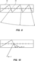
- a waveguide having an embedded diffraction grating; such waveguides are available, for example, from suppliers such as BAE Systems PLC of London, U.K. and may be utilized to intake an image from the left of Figure 9 as shown, pass the image through the embedded diffraction grating (44) , and pass the resultant image out at an angle (in Figure 9 , for example, through the side of the waveguide) .
- an angle in Figure 9 , for example, through the side of the waveguide
- off - axis focal techniques such as those described in reference to Figure 8C
- an AAD system comprises an imaging module (46, 48) in front of each eye (4, 6) through which the user sees the world.
- Figure 11B illustrates a larger view of the module (46) with its associated (coupled via the depicted electronic control leads; leads may also be wireless) controller (66) , which may be a microprocessor, microcontroller, field programmable gate array (FPGA) , application specific integrated circuit (ASIC), or the like.
- the controller preferably is coupled to a power supply and also an information exchange device, such as a wireless internet or Bluetooth adaptor, to allow for the exchange of information between the outside world and the controller (66) .
- the system may be configured to operate at an image refresh rate, such as a rate between 30 and 60 frames per second.
- the controller may be configured to operate a high-refresh rate digital high resolution display (52) , such as a ferro-liquid, bluephase, or bent-core display, to display various zone plate geometries quickly in succession, pertinent to each of the 12 or so depth layers.
- a high-refresh rate digital high resolution display (52) such as a ferro-liquid, bluephase, or bent-core display
- the zone plate display (52) may be operated at 12 times this, or 720Hz, to be able to provide simulated accommodation to each of the 12 depth layers as shown in Figure 3B .
- the occluding mask display (54) is configured to display a blacked out image geometrically corresponding to the image displayed before it on the transparent projector layer (56) - blacked out to prevent light from the other side of the occluding mask display from bleeding through or interfering with display of a desired virtual or augmented image in the projector layer (56) .
- Figures 12A-12B depict another embodiment wherein an imaging module (58) comprises high-resolution mini projector oriented at an angle approximately perpendicular to the visual axis of the eye; a waveguide comprising a substrate guided delay exit pupil expander device (70) magnifies and redirects the image from the small mini projector and into the zone plate layer (52); the occluding layer (54) provides similar masking functions to protect perception of the projected images from background lighting.
- Figures 13A-13B depict another embodiment wherein elements 52 and 70 are combined such that the zone plate and projecting layer are essentially housed within the same integrated module (72) which intakes a small image from the mini projector (68) , redirects and magnifies it, and also diffracts it, for passage to the eye; the occluding layer (54) provides similar masking functions to protect perception of the projected images from background lighting.
- the invention includes methods that may be performed using the subject devices.
- the methods may comprise the act of providing such a suitable device.
- Such provision may be performed by the end user.
- the "providing" act merely requires the end user obtain, access, approach, position, set-up, activate, power-up or otherwise act to provide the requisite device in the subject method.
Description
- The present invention relates to virtual reality and augmented reality imaging and visualization systems.
- In order for a 3D display to produce a true sensation of depth, and more specifically, a simulated sensation of surface depth, it is desirable for each point in the display's visual field to generate the accommodative response corresponding to its virtual depth. If the accommodative response to a display point does not correspond to the virtual depth of that point, as determined by the binocular depth cues of convergence and stereopsis, the human eye may experience an accommodation conflict, resulting in unstable imaging, harmful eye strain, headaches, and, in the absence of accommodation information, almost a complete lack of surface depth. Referring to
Figure 1 , an augmented reality scenario (8) is depicted with views to the user of actual objects within the user's reality, such as landscaping items including a concrete stage object (1120) in a park setting, and also views of virtual objects added into the view to produce the "augmented" reality view; here a robot statue (1110) is shown virtually standing upon the stage object (1120), and a bee character (2) is shown flying in the airspace near the user's head. Preferably the augmented reality system is 3-D capable, in which case it provides the user with the perception that the statue (1110) is standing on the stage (1120) , and that the bee character (2) is flying close to the user's head. This perception may be greatly enhanced by utilizing visual accommodation cues to the user's eye and brain that the virtual objects (2, 1110) have different depths of focus, and that the depth of focus or focal radii for the robot statue (1110) is approximately the same as that for the stage (1120) . Conventional stereoscopic 3-D simulation display systems, such as that depicted inFigure 2 , typically have two displays (74, 76), one for each eye, at a fixed radial focal distance (10) . As stated above, this conventional technology misses many of the valuable cues utilized by the human eye and brain to detect and interpret depth in three dimensions, including the accommodation cue, which is associated with the eye's repositioning of the crystalline lens within the eye complex to reach a different depth of focus with the eye. There is a need for an accommodation accurate display system which takes into account the accommodation aspects of the human eye/brain image processing complex. - Patent document
US 2010/157433 A1 discloses a head-mounted display comprising both image display and image generation devices. Several designs of head-mounted displays having a form mfactor similar to conventional glasses are discussed herin. - Patent document
US 2010/149611 A1 discloses a method and device for reconstructing a three-dimensional scene in a holographic display. - Cakmakci et al. ("Head-Worn Displays: a review", J. of Display Tech., vol. 2, no.3, 2006-09, pp. 199-216) provides an overview of existing head-worn display technologies.
- The present invention relates to a system as defined in
claim 1. - One embodiment is directed to a three-dimensional image visualization system, comprising a selectively transparent projection device for projecting an image toward an eye of a viewer from a projection device position in space relative to the eye of the viewer, the projection device being capable of assuming a substantially transparent state when no image is projected; an occlusion mask device coupled to the projection device and configured to selectively block light traveling toward the eye from one or more positions opposite of the projection device from the eye of the viewer in an occluding pattern correlated with the image projected by the projection device; and a zone plate diffraction patterning device interposed between the eye of the viewer and the projection device and configured to cause light from the projection device to pass through a diffraction pattern having a selectable geometry as it travels to the eye and enter the eye with a simulated focal distance from the eye based at least in part upon the selectable geometry of the diffraction pattern. The system further may comprise a controller operatively coupled to the projection device, occlusion mask device, and the zone plate diffraction patterning device and configured to coordinate projection of the image and associated occluding pattern, as well as interposition of the diffraction pattern at the selectable geometry. The controller may comprise a microprocessor. The projection device may comprise a substantially planar transparent digital display substantially occupying a display plane. The display plane may be oriented substantially perpendicularly from a visual axis of the eye of the viewer. The substantially planar transparent digital display may comprise a liquid crystal display. The substantially planar transparent digital display may comprise an organic light emitting diode display. The projection device may be configured to project the image toward the eye in a collimated form such that the depth of focus for the eye of the viewer is an infinite depth of focus. The projection device may comprise a high-speed mini-projector coupled to a substrate- guided delay exit pupil expander device configured to expand the size of the image before delivery to the eye of the viewer. The mini -projector may be mounted substantially perpendicularly to a visual axis of the eye of the viewer, and wherein the substrate- guided delay exit pupil expander device is configured to receive the image from the mini -proj ector and deliver it to the zone plate diffraction patterning device and to the eye of the viewer in the expanded size with an orientation substantially aligned with the visual axis of the eye. The zone plate diffraction patterning device and projection device may comprise at least one common structure. The zone plate diffraction patterning device may be integrated into a waveguide, such that the projection device comprises a high-speed mini-projector coupled to the waveguide and configured pass the image through the diffraction pattern before the image exits the waveguide en route to the eye of the viewer. The mini -proj ector may be mounted substantially perpendicularly to a visual axis of the eye of the viewer, and the waveguide may be configured to receive the image from the mini -proj ector and deliver it to the eye of the viewer in an expanded size with an orientation substantially aligned with the visual axis of the eye. The occlusion mask device my comprise a display configured to either occlude or pass light at each of a plurality of portions of the display, depending upon a pertinent command to occlude or pass light at each portion. The occlusion mask device may comprise one or more liquid crystal displays. The zone plate diffraction patterning device may comprise a high-frequency binary display configured to either occlude or pass light at each of a plurality of portions of the display, depending upon a pertinent command to occlude or pass light at each portion. The zone plate diffraction patterning device may have a refresh rate of between about 500Hz and about 2,000Hz. The zone plate diffraction patterning device may have a refresh rate of about 720Hz. The controller may be configured to operate the projection device and occlusion mask device at between about 30 and about 60 frames per second, and to operate the zone plate diffraction patterning device to digitally display up to about 12 different diffraction patterns for each frame of the projection device and occlusion mask device. The projection device, occlusion mask device, and the zone plate diffraction patterning device collectively may comprise an imaging module for a single eye of the viewer, and the system further may comprise a second imaging module for another eye of the viewer.
-
-
Figure 1 depicts an illustration of an augmented reality- scenario with certain virtual reality objects, and certain actual reality objects viewed by a person. -
Figure 2 illustrates a conventional stereoscopy system to simulate three-dimensional imaging for the user. -
Figures 3A and3B illustrate aspects of an accommodation accurate display configuration. -
Figures 4A-4C illustrate relationships between radius of curvature and focal radius . -
Figures 5-6C illustrate aspects of diffraction gratings as applied to the subject configurations. -
Figures 7A-7C illustrate three different focal mechanisms. -
Figure 7D illustrates a Fresnel zone plate. -
Figures 8A-8C illustrate various aspects of diffraction system focusing issues. -
Figure 9 illustrates one embodiment of a waveguide with embedded diffraction grating. -
Figure 10 illustrates one embodiment of a waveguide with embedded diffraction grating designed to allow one mode to escape and the other modes to remain trapped in the waveguide .Figures 11A-11B illustrate aspects of a diffractive imaging module embodiment . -
Figures 12A-12B illustrate aspects of a diffractive imaging module embodiment. -
Figures 13A-13B illustrate aspects of a diffractive imaging module embodiment. - Referring to
Figures 3A and3B , various aspects of an AAD system are depicted. Referring toFigure 3A , a simple illustration shows that in the place of two conventional displays as in stereoscopy (Figure 2 ), two complex images, one for each eye, with various radial focal depths (12) for various aspects (14) of each image may be utilized to provide each eye with the perception of three dimensional depth layering within the perceived image. - Referring to
Figure 3B , we have determined that the typical human eye is able to interpret approximately 12 layers (layers L1-L12 inFigure 3B - drawing element 16) of depth based upon radial distance. A near field limit (78) of about 0.25 meters is about the closest depth of focus; a far-field limit (80) of about 3 meters means that any item farther than about 3 meters from the human eye receives infinite focus. The layers of focus get more and more thin as one gets closer to the eye; in other words, the eye is able to perceive differences in focal distance that are quite small relatively close to the eye, and this effect dissipates as objects fall farther away from the eye, as shown inFigure 3B .Element 82 illustrates that at an infinite object location, a depth of focus / dioptric spacing value is about 1/3 diopters. One other way of describing the import ofFigure 3B : there are about twelve focal planes between the eye of the user and infinity. These focal planes, and the data within the depicted relationships, may be utilized to position virtual elements within an augmented reality scenario for a user's viewing, because the human eye is constantly sweeping around to utilize the focal planes to perceive depth. Referring toFigures 4A-4C , if K(R) is a dynamic parameter for curvature equal to 1/R, where R is the focal radius of an item relative to a surface, then with increasing radius (R3, to R2, up to R1) , you have decreasing K(R) . The light field produced by a point has a spherical curvature, which is a function of how far away the point is from the eye of the user. This relationship may also be utilized for AAD systems. - Referring to
Figure 5 , a conventional diffraction grating (22) is shown, with light passing through the grating spacing (18) at an angle (theta - 20) which is related to the diffraction order (n) , spatial frequency, and K factor, which equals 1/d, using the following equation:
d*sin (theta) =n*wavelength (or alternatively substituting the K factor, sin (theta) = n*wavelength*K.Figures 6A-6C illustrate that with decreased spacing (18, 28, 30) in the diffraction pattern (22, 24, 26), the angle (20, 32, 34) becomes greater. - Referring to
Figure 7A-7C , three different focusing mechanisms are depicted - refraction through a lens (36) , reflection with a curved mirror (38) , and diffraction with a Fresnel zone plate (40) , also shown inFigure 7D (40). - Referring to
Figure 8A , a simplified version of diffraction is shown to illustrate that an N=-1 mode could correspond to a virtual image; an N=+1 mode could correspond to a real image, and an N=0 mode could correspond to a focused-at - infinity image. These images could be confusing to the human eye and brain, and particularly problematic if all focused on-axis, as shown inFigure 8B . Referring toFigure 8C , an off -axis focus configuration may be utilized to allow for blocking of modes/images that are unwanted. For example, a collimated (r = infinity) image may be formed by the N=0 mode; a divergent virtual image may be formed by the N=-1 mode; and a convergent image may be formed by the N=+1 mode. The difference in spatial location of these modes/images and their trajectories allows for filtering out or separation to prevent the aforementioned problems associated with diffraction imaging, such as overlaying, ghosting, and "multiple exposure" perception effects. - Referring to
Figure 9 , a waveguide is shown having an embedded diffraction grating; such waveguides are available, for example, from suppliers such as BAE Systems PLC of London, U.K. and may be utilized to intake an image from the left ofFigure 9 as shown, pass the image through the embedded diffraction grating (44) , and pass the resultant image out at an angle (inFigure 9 , for example, through the side of the waveguide) . Thus a dual use of redirection and diffraction may be achieved with such an element. Indeed, off - axis focal techniques, such as those described in reference toFigure 8C , may be combined with diffraction waveguide elements such as that shown inFigure 9 to result in a configuration such as that shown inFigure 10 , wherein not only are redirection and diffraction accomplished, but also filtering, since in the depicted embodiment the geometry of the diffracting waveguide is such that the N=-1 mode (say the virtual image) is passed out of the waveguide and into the eye of the user, and the other two modes (N=0 and N=+1) are trapped inside of the waveguide by reflection. - Referring to
Figures 11A -13C, the aforementioned concepts are put into play with various augmented reality display configurations. - Referring to
Figure 11A , an AAD system comprises an imaging module (46, 48) in front of each eye (4, 6) through which the user sees the world.Figure 11B illustrates a larger view of the module (46) with its associated (coupled via the depicted electronic control leads; leads may also be wireless) controller (66) , which may be a microprocessor, microcontroller, field programmable gate array (FPGA) , application specific integrated circuit (ASIC), or the like. The controller preferably is coupled to a power supply and also an information exchange device, such as a wireless internet or Bluetooth adaptor, to allow for the exchange of information between the outside world and the controller (66) . The system may be configured to operate at an image refresh rate, such as a rate between 30 and 60 frames per second. The controller may be configured to operate a high-refresh rate digital high resolution display (52) , such as a ferro-liquid, bluephase, or bent-core display, to display various zone plate geometries quickly in succession, pertinent to each of the 12 or so depth layers. For example, in an embodiment wherein 60 frames per second overall performance is desired, the zone plate display (52) may be operated at 12 times this, or 720Hz, to be able to provide simulated accommodation to each of the 12 depth layers as shown inFigure 3B . The occluding mask display (54) is configured to display a blacked out image geometrically corresponding to the image displayed before it on the transparent projector layer (56) - blacked out to prevent light from the other side of the occluding mask display from bleeding through or interfering with display of a desired virtual or augmented image in the projector layer (56) . Thus in an augmented reality configuration, as shown, light from the real background passes through the non-masked portions of the occlusion mask (54), though the transparent (i.e., not broadcasting a portion of an image) portions of the transparent projector layer (56) , and into the zone plate layer (52) for accommodation treatment; images projected at the projecting layer (56) receive mask blocking from background light at the occlusion layer (54) and are projected forward into the zone plate layer (52) for accommodation treatment. The combination of these, or the associated perception of the augmented reality to the user, is very close to "true 3-D". -
Figures 12A-12B depict another embodiment wherein an imaging module (58) comprises high-resolution mini projector oriented at an angle approximately perpendicular to the visual axis of the eye; a waveguide comprising a substrate guided delay exit pupil expander device (70) magnifies and redirects the image from the small mini projector and into the zone plate layer (52); the occluding layer (54) provides similar masking functions to protect perception of the projected images from background lighting. -
Figures 13A-13B depict another embodiment whereinelements - Various exemplary embodiments of the invention are described herein.
- Reference is made to these examples in a non- limiting sense. They are provided to illustrate more broadly applicable aspects of the invention. Various changes may be made to the invention described and equivalents may be substituted without departing from the scope of the appended claims. In addition, many modifications may be made to adapt a particular situation, material, composition of matter, process, process act(s) or step(s) to the obj ective (s) of the present invention. Further, as will be appreciated by those with skill in the art that each of the individual variations described and illustrated herein has discrete components and features which may be readily separated from or combined with the features of any of the other several embodiments without departing from the scope of the present inventions. All such modifications are intended to be within the scope of claims associated with this disclosure.
- The invention includes methods that may be performed using the subject devices. The methods may comprise the act of providing such a suitable device. Such provision may be performed by the end user. In other words, the "providing" act merely requires the end user obtain, access, approach, position, set-up, activate, power-up or otherwise act to provide the requisite device in the subject method.
- Methods recited herein may be carried out in any order of the recited events which is logically possible, as well as in the recited order of events.
- Exemplary aspects of the invention, together with details regarding material selection and manufacture have been set forth above. As for other details of the present invention, these may be appreciated in connection with the above -referenced patents and publications as well as generally known or appreciated by those with skill in the art. The same may hold true with respect to method-based aspects of the invention in terms of additional acts as commonly or logically employed.
- In addition, though the invention has been described in reference to several examples optionally incorporating various features, the invention is not to be limited to that which is described or indicated as contemplated with respect to each variation of the invention. Various changes may be made to the invention described and equivalents (whether recited herein or not included for the sake of some brevity) may be substituted unless they depart from the scope of the appended claims. In addition, where a range of values is provided, it is understood that every intervening value, between the upper and lower limit of that range and any other stated or intervening value in that stated range, is encompassed within the invention as defined by appended claims.
Claims (15)
- A three-dimensional image visualization system, comprising: an integrated module (72) comprising:a selectively transparent projection device (56) configured tcreceive input image light and project an image associated with the input image light toward an eye of a viewer from a projection device (56) positionin space relative to the eye of the viewer, the projection device (56) being capable of assuming a substantially transparent state when no image is projected; anda zone plate diffraction patterning device (52) comprising a diffraction waveguide element configured to divide the input image light into a plurality of modes, each of the plurality of modes directed at a different angle, wherein the projection device (56) is formed by ahigh-resolution mini projector (68) oriented at an angle approximately perpendicular to the visual axis of the eye and a waveguide comprising a substrate guided delay exit pupil expander device (70) arranged to magnify and redirect the image from the mini projector (68) and into the zone plate diffraction patterning device (52), wherein the integrated module is configured to allowat least a first mode of the plurality of modes to exit the integrated module toward the eye, the first mode having a simulated focal distance based in part on a selectable geometry of the zone plate diffraction patterning device, and wherein the integrated module is configured to trap at least a second mode of the plurality of modes within the diffraction waveguide element; and an occlusion mask device (54) coupled to the selectively transparent projection device (56) and configured to selectively block light traveling toward the eye from one or more positions opposite of the occlusion mask from the eye of the viewer in an occluding pattern correlated with the image projected by the selectively transparent projection device (56).
- The system of claim 1, further comprising a controller (66) operatively coupled to the integrated module (72) and the occlusion mask device (54), and configured to coordinate projection of the image and associated occluding pattern.
- The system of claim 2, wherein the controller (66) comprises a microprocessor.
- The system of claim 1, wherein the selectively transparent projection device (56) comprises a substantially planar transparent digital display substantially occupying a display plane.
- The system of claim 4, wherein the display plane is oriented substantially orthogonal to a visual axis of the eye of the viewer.
- The system of claim 1, wherein the selectively transparent projection device (56) is configured to project the image toward the eye in a collimated form such that the image is focused at infinity.
- The system of claim 1, wherein the diffraction waveguide element comprises a substrate-guided delay exit pupil expander device (70) configured to expand the size of the image before delivery to the eye of the viewer.
- The system of claim 1, wherein the mini-projector is mounted substantially perpendicularly to a visual axis of the eye of the viewer, and wherein the substrate-guided delay exit pupil expander device (70) is configured to receive the image from the mini-projector and deliver it to the zone plate diffraction patterning device (52) and to the eye of the viewer in the expanded size with an orientation substantially aligned with the visual axis of the eye.
- The system of claim 1, wherein the occlusion mask device (54) comprises a display configured to either occlude or pass light at each of a plurality of portions of the display, depending upon a pertinent command to occlude or pass light at each portion.
- The system of claim 1, wherein the occlusion mask device (54) comprises one or more liquid crystal displays.
- The system of claim 1, wherein the second mode of the plurality of modes comprises the 0th order of diffraction.
- The system of claim 1, wherein the integrated module is further configured to allow a third mode of the plurality of modes to exit the integrated module.
- The system of claim 1, wherein the integrated module is further configured to trap a third mode of the plurality of modes within the diffraction waveguide element.
- The system of any one of claims 12-13, wherein the third mode comprises the positive of a 1st order of diffraction.
- The system of any one of claims 12-13, wherein the third mode comprises the negative of a 1st order of diffraction.
Priority Applications (1)
| Application Number | Priority Date | Filing Date | Title |
|---|---|---|---|
| EP22163415.7A EP4036862A1 (en) | 2011-11-23 | 2012-11-23 | Three dimensional virtual and augmented reality display system |
Applications Claiming Priority (3)
| Application Number | Priority Date | Filing Date | Title |
|---|---|---|---|
| US201161563403P | 2011-11-23 | 2011-11-23 | |
| EP12851157.3A EP2783352B1 (en) | 2011-11-23 | 2012-11-23 | Three dimensional virtual and augmented reality display system |
| PCT/US2012/000560 WO2013077895A1 (en) | 2011-11-23 | 2012-11-23 | Three dimensional virtual and augmented reality display system |
Related Parent Applications (2)
| Application Number | Title | Priority Date | Filing Date |
|---|---|---|---|
| EP12851157.3A Division EP2783352B1 (en) | 2011-11-23 | 2012-11-23 | Three dimensional virtual and augmented reality display system |
| EP12851157.3A Division-Into EP2783352B1 (en) | 2011-11-23 | 2012-11-23 | Three dimensional virtual and augmented reality display system |
Related Child Applications (1)
| Application Number | Title | Priority Date | Filing Date |
|---|---|---|---|
| EP22163415.7A Division EP4036862A1 (en) | 2011-11-23 | 2012-11-23 | Three dimensional virtual and augmented reality display system |
Publications (2)
| Publication Number | Publication Date |
|---|---|
| EP3503035A1 EP3503035A1 (en) | 2019-06-26 |
| EP3503035B1 true EP3503035B1 (en) | 2022-03-23 |
Family
ID=48426562
Family Applications (3)
| Application Number | Title | Priority Date | Filing Date |
|---|---|---|---|
| EP22163415.7A Pending EP4036862A1 (en) | 2011-11-23 | 2012-11-23 | Three dimensional virtual and augmented reality display system |
| EP12851157.3A Active EP2783352B1 (en) | 2011-11-23 | 2012-11-23 | Three dimensional virtual and augmented reality display system |
| EP19154686.0A Active EP3503035B1 (en) | 2011-11-23 | 2012-11-23 | Three dimensional virtual and augmented reality display system |
Family Applications Before (2)
| Application Number | Title | Priority Date | Filing Date |
|---|---|---|---|
| EP22163415.7A Pending EP4036862A1 (en) | 2011-11-23 | 2012-11-23 | Three dimensional virtual and augmented reality display system |
| EP12851157.3A Active EP2783352B1 (en) | 2011-11-23 | 2012-11-23 | Three dimensional virtual and augmented reality display system |
Country Status (11)
| Country | Link |
|---|---|
| US (8) | US8950867B2 (en) |
| EP (3) | EP4036862A1 (en) |
| JP (5) | JP6250547B2 (en) |
| KR (6) | KR102376368B1 (en) |
| CN (2) | CN104067316B (en) |
| AU (5) | AU2012341069B2 (en) |
| BR (1) | BR112014012615A2 (en) |
| CA (2) | CA2858208C (en) |
| IL (2) | IL232746A (en) |
| RU (1) | RU2628164C2 (en) |
| WO (1) | WO2013077895A1 (en) |
Families Citing this family (225)
| Publication number | Priority date | Publication date | Assignee | Title |
|---|---|---|---|---|
| GB0522968D0 (en) | 2005-11-11 | 2005-12-21 | Popovich Milan M | Holographic illumination device |
| GB0718706D0 (en) | 2007-09-25 | 2007-11-07 | Creative Physics Ltd | Method and apparatus for reducing laser speckle |
| US11726332B2 (en) | 2009-04-27 | 2023-08-15 | Digilens Inc. | Diffractive projection apparatus |
| US9335604B2 (en) | 2013-12-11 | 2016-05-10 | Milan Momcilo Popovich | Holographic waveguide display |
| US11204540B2 (en) | 2009-10-09 | 2021-12-21 | Digilens Inc. | Diffractive waveguide providing a retinal image |
| US9274349B2 (en) | 2011-04-07 | 2016-03-01 | Digilens Inc. | Laser despeckler based on angular diversity |
| EP2748670B1 (en) | 2011-08-24 | 2015-11-18 | Rockwell Collins, Inc. | Wearable data display |
| US10670876B2 (en) | 2011-08-24 | 2020-06-02 | Digilens Inc. | Waveguide laser illuminator incorporating a despeckler |
| WO2016020630A2 (en) | 2014-08-08 | 2016-02-11 | Milan Momcilo Popovich | Waveguide laser illuminator incorporating a despeckler |
| US20150010265A1 (en) | 2012-01-06 | 2015-01-08 | Milan, Momcilo POPOVICH | Contact image sensor using switchable bragg gratings |
| WO2013163347A1 (en) | 2012-04-25 | 2013-10-31 | Rockwell Collins, Inc. | Holographic wide angle display |
| WO2013167864A1 (en) | 2012-05-11 | 2013-11-14 | Milan Momcilo Popovich | Apparatus for eye tracking |
| US9671566B2 (en) | 2012-06-11 | 2017-06-06 | Magic Leap, Inc. | Planar waveguide apparatus with diffraction element(s) and system employing same |
| US9933684B2 (en) * | 2012-11-16 | 2018-04-03 | Rockwell Collins, Inc. | Transparent waveguide display providing upper and lower fields of view having a specific light output aperture configuration |
| US11504051B2 (en) | 2013-01-25 | 2022-11-22 | Wesley W. O. Krueger | Systems and methods for observing eye and head information to measure ocular parameters and determine human health status |
| US11490809B2 (en) | 2013-01-25 | 2022-11-08 | Wesley W. O. Krueger | Ocular parameter-based head impact measurement using a face shield |
| US10209517B2 (en) | 2013-05-20 | 2019-02-19 | Digilens, Inc. | Holographic waveguide eye tracker |
| US9874749B2 (en) | 2013-11-27 | 2018-01-23 | Magic Leap, Inc. | Virtual and augmented reality systems and methods |
| US10262462B2 (en) | 2014-04-18 | 2019-04-16 | Magic Leap, Inc. | Systems and methods for augmented and virtual reality |
| US10228242B2 (en) | 2013-07-12 | 2019-03-12 | Magic Leap, Inc. | Method and system for determining user input based on gesture |
| WO2015006784A2 (en) * | 2013-07-12 | 2015-01-15 | Magic Leap, Inc. | Planar waveguide apparatus with diffraction element(s) and system employing same |
| US9727772B2 (en) | 2013-07-31 | 2017-08-08 | Digilens, Inc. | Method and apparatus for contact image sensing |
| US9633504B2 (en) | 2013-11-22 | 2017-04-25 | Michael J Kline | System, method, and apparatus for purchasing, dispensing, or sampling of products |
| US9527716B2 (en) | 2013-11-22 | 2016-12-27 | Michael J. Kline | System, method, and apparatus for purchasing, dispensing, or sampling of products |
| US9701530B2 (en) | 2013-11-22 | 2017-07-11 | Michael J. Kline | System, method, and apparatus for purchasing, dispensing, or sampling of products |
| KR102651578B1 (en) * | 2013-11-27 | 2024-03-25 | 매직 립, 인코포레이티드 | Virtual and augmented reality systems and methods |
| US9857591B2 (en) | 2014-05-30 | 2018-01-02 | Magic Leap, Inc. | Methods and system for creating focal planes in virtual and augmented reality |
| CN103676175A (en) * | 2013-12-26 | 2014-03-26 | 无锡锡飞光电科技有限公司 | Naked eye three-dimension display method |
| EP3100098B8 (en) * | 2014-01-31 | 2022-10-05 | Magic Leap, Inc. | Multi-focal display system and method |
| EP3100099B1 (en) * | 2014-01-31 | 2020-07-01 | Magic Leap, Inc. | Multi-focal display system and method |
| US10430985B2 (en) | 2014-03-14 | 2019-10-01 | Magic Leap, Inc. | Augmented reality systems and methods utilizing reflections |
| US11138793B2 (en) | 2014-03-14 | 2021-10-05 | Magic Leap, Inc. | Multi-depth plane display system with reduced switching between depth planes |
| WO2015161307A1 (en) * | 2014-04-18 | 2015-10-22 | Magic Leap, Inc. | Systems and methods for augmented and virtual reality |
| CN112987307B (en) * | 2014-05-30 | 2022-06-28 | 奇跃公司 | Method and system for generating focal planes in virtual and augmented reality |
| AU2015266670B2 (en) | 2014-05-30 | 2019-05-09 | Magic Leap, Inc. | Methods and systems for displaying stereoscopy with a freeform optical system with addressable focus for virtual and augmented reality |
| US10359736B2 (en) | 2014-08-08 | 2019-07-23 | Digilens Inc. | Method for holographic mastering and replication |
| US10241330B2 (en) | 2014-09-19 | 2019-03-26 | Digilens, Inc. | Method and apparatus for generating input images for holographic waveguide displays |
| EP3198192A1 (en) | 2014-09-26 | 2017-08-02 | Milan Momcilo Popovich | Holographic waveguide opticaltracker |
| WO2016054092A1 (en) * | 2014-09-29 | 2016-04-07 | Magic Leap, Inc. | Architectures and methods for outputting different wavelength light out of waveguides |
| US10015477B2 (en) * | 2014-12-29 | 2018-07-03 | Magic Leap, Inc. | Light projector using an acousto-optical control device |
| US20180275402A1 (en) | 2015-01-12 | 2018-09-27 | Digilens, Inc. | Holographic waveguide light field displays |
| CN107873086B (en) | 2015-01-12 | 2020-03-20 | 迪吉伦斯公司 | Environmentally isolated waveguide display |
| US10330777B2 (en) | 2015-01-20 | 2019-06-25 | Digilens Inc. | Holographic waveguide lidar |
| US10657780B1 (en) | 2015-01-29 | 2020-05-19 | Transparensee Llc | System, method, and apparatus for mixing, blending, dispensing, monitoring, and labeling products |
| US9632226B2 (en) | 2015-02-12 | 2017-04-25 | Digilens Inc. | Waveguide grating device |
| US11468639B2 (en) | 2015-02-20 | 2022-10-11 | Microsoft Technology Licensing, Llc | Selective occlusion system for augmented reality devices |
| US10838207B2 (en) * | 2015-03-05 | 2020-11-17 | Magic Leap, Inc. | Systems and methods for augmented reality |
| US10180734B2 (en) | 2015-03-05 | 2019-01-15 | Magic Leap, Inc. | Systems and methods for augmented reality |
| WO2016141373A1 (en) | 2015-03-05 | 2016-09-09 | Magic Leap, Inc. | Systems and methods for augmented reality |
| WO2016146963A1 (en) | 2015-03-16 | 2016-09-22 | Popovich, Milan, Momcilo | Waveguide device incorporating a light pipe |
| KR102634148B1 (en) | 2015-03-16 | 2024-02-05 | 매직 립, 인코포레이티드 | Methods and system for diagnosing and treating health ailments |
| US10404975B2 (en) | 2015-03-20 | 2019-09-03 | Tilt Five, Inc | Retroreflective light field display |
| US10591756B2 (en) | 2015-03-31 | 2020-03-17 | Digilens Inc. | Method and apparatus for contact image sensing |
| CN106293561B (en) | 2015-05-28 | 2020-02-28 | 北京智谷睿拓技术服务有限公司 | Display control method and device and display equipment |
| CN106303315B (en) | 2015-05-30 | 2019-08-16 | 北京智谷睿拓技术服务有限公司 | Video display control method and device, display equipment |
| CN106303498B (en) | 2015-05-30 | 2018-10-16 | 北京智谷睿拓技术服务有限公司 | Video display control method and device, display equipment |
| CN106303499B (en) | 2015-05-30 | 2018-10-16 | 北京智谷睿拓技术服务有限公司 | Video display control method and device, display equipment |
| EP4249965A3 (en) | 2015-06-15 | 2023-12-27 | Magic Leap, Inc. | Display system with optical elements for in-coupling multiplexed light streams |
| US10492981B1 (en) | 2015-07-17 | 2019-12-03 | Bao Tran | Systems and methods for computer assisted operation |
| US10335572B1 (en) | 2015-07-17 | 2019-07-02 | Naveen Kumar | Systems and methods for computer assisted operation |
| US10176642B2 (en) | 2015-07-17 | 2019-01-08 | Bao Tran | Systems and methods for computer assisted operation |
| US10685488B1 (en) | 2015-07-17 | 2020-06-16 | Naveen Kumar | Systems and methods for computer assisted operation |
| US10149958B1 (en) | 2015-07-17 | 2018-12-11 | Bao Tran | Systems and methods for computer assisted operation |
| CN107850784B (en) | 2015-07-20 | 2021-06-01 | 奇跃公司 | Collimated fiber scanner design with inward pointing angle in virtual/augmented reality systems |
| CN108140259B (en) | 2015-08-18 | 2022-06-14 | 奇跃公司 | Virtual and augmented reality systems and methods |
| EP3337383A4 (en) | 2015-08-21 | 2019-04-03 | Magic Leap, Inc. | Eyelid shape estimation |
| CA2996039A1 (en) | 2015-08-21 | 2017-03-02 | Magic Leap, Inc. | Eyelid shape estimation using eye pose measurement |
| US10681489B2 (en) | 2015-09-16 | 2020-06-09 | Magic Leap, Inc. | Head pose mixing of audio files |
| CA2999261C (en) | 2015-09-23 | 2022-10-18 | Magic Leap, Inc. | Eye imaging with an off-axis imager |
| CN108139587A (en) | 2015-10-05 | 2018-06-08 | 奇跃公司 | For scanning the lenticule collimator of optical fiber in virtual/augmented reality system |
| EP3359999A1 (en) | 2015-10-05 | 2018-08-15 | Popovich, Milan Momcilo | Waveguide display |
| JP7216547B2 (en) | 2015-10-06 | 2023-02-01 | マジック リープ, インコーポレイテッド | Virtual/Augmented Reality Systems with Inverse Angle Gratings |
| CN114140867A (en) | 2015-10-16 | 2022-03-04 | 奇跃公司 | Eye pose recognition using eye features |
| EP3365724B1 (en) | 2015-10-20 | 2021-05-05 | Magic Leap, Inc. | Selecting virtual objects in a three-dimensional space |
| US9709807B2 (en) | 2015-11-03 | 2017-07-18 | Motorola Solutions, Inc. | Out of focus notifications |
| JP7210280B2 (en) | 2015-11-04 | 2023-01-23 | マジック リープ, インコーポレイテッド | Light field display measurement |
| US11231544B2 (en) | 2015-11-06 | 2022-01-25 | Magic Leap, Inc. | Metasurfaces for redirecting light and methods for fabricating |
| AU2016365422A1 (en) | 2015-12-04 | 2018-06-28 | Magic Leap, Inc. | Relocalization systems and methods |
| NZ743880A (en) * | 2016-01-07 | 2023-01-27 | Magic Leap Inc | Dynamic fresnel projector |
| WO2017120372A1 (en) | 2016-01-07 | 2017-07-13 | Magic Leap, Inc. | Virtual and augmented reality systems and methods having unequal numbers of component color images distributed across depth planes |
| CN113156650A (en) | 2016-01-19 | 2021-07-23 | 奇跃公司 | Augmented reality system and method using images |
| WO2017127366A1 (en) | 2016-01-19 | 2017-07-27 | Magic Leap, Inc. | Eye image collection, selection, and combination |
| WO2017127547A1 (en) | 2016-01-20 | 2017-07-27 | Magic Leap, Inc. | Polarizing maintaining optical fiber in virtual/augmented reality system |
| CN108885352B (en) | 2016-01-29 | 2021-11-23 | 奇跃公司 | Display of three-dimensional images |
| WO2017134412A1 (en) | 2016-02-04 | 2017-08-10 | Milan Momcilo Popovich | Holographic waveguide optical tracker |
| KR20180114162A (en) | 2016-02-24 | 2018-10-17 | 매직 립, 인코포레이티드 | Polarizing beam splitter with low light leakage |
| CN108700275B (en) | 2016-02-24 | 2022-05-31 | 奇跃公司 | Low profile interconnect for light emitter |
| WO2017147534A1 (en) | 2016-02-26 | 2017-08-31 | Magic Leap, Inc. | Display system having a plurality of light pipes for a plurality of light emitters |
| EP3420601B1 (en) | 2016-02-26 | 2023-08-02 | Magic Leap, Inc. | Optical system |
| KR20180117181A (en) | 2016-03-01 | 2018-10-26 | 매직 립, 인코포레이티드 | A reflective switching device for inputting light of different wavelengths into waveguides |
| AU2017225977C1 (en) | 2016-03-04 | 2023-08-03 | Magic Leap, Inc. | Current drain reduction in AR/VR display systems |
| US10089453B2 (en) | 2016-03-07 | 2018-10-02 | Magic Leap, Inc. | Blue light adjustment for biometric identification |
| EP3779740B1 (en) | 2016-03-22 | 2021-12-08 | Magic Leap, Inc. | Head mounted display system configured to exchange biometric information |
| EP3433659A1 (en) | 2016-03-24 | 2019-01-30 | DigiLens, Inc. | Method and apparatus for providing a polarization selective holographic waveguide device |
| AU2017238847A1 (en) | 2016-03-25 | 2018-10-04 | Magic Leap, Inc. | Virtual and augmented reality systems and methods |
| CN114995594A (en) | 2016-03-31 | 2022-09-02 | 奇跃公司 | Interaction with 3D virtual objects using gestures and multi-DOF controllers |
| JP6923552B2 (en) | 2016-04-08 | 2021-08-18 | マジック リープ, インコーポレイテッドMagic Leap,Inc. | Augmented reality systems and methods with varifocal lens elements |
| WO2017178781A1 (en) | 2016-04-11 | 2017-10-19 | GRANT, Alastair, John | Holographic waveguide apparatus for structured light projection |
| KR20230098916A (en) | 2016-04-21 | 2023-07-04 | 매직 립, 인코포레이티드 | Visual aura around field of view |
| AU2017257549B2 (en) | 2016-04-26 | 2021-09-09 | Magic Leap, Inc. | Electromagnetic tracking with augmented reality systems |
| US10046229B2 (en) | 2016-05-02 | 2018-08-14 | Bao Tran | Smart device |
| NZ747834A (en) | 2016-05-06 | 2023-06-30 | Magic Leap Inc | Metasurfaces with asymmetric gratings for redirecting light and methods for fabricating |
| JP7021110B2 (en) | 2016-05-09 | 2022-02-16 | マジック リープ, インコーポレイテッド | Augmented reality systems and methods for user health analysis |
| US9904058B2 (en) | 2016-05-12 | 2018-02-27 | Magic Leap, Inc. | Distributed light manipulation over imaging waveguide |
| EP3459071B1 (en) | 2016-05-20 | 2022-05-11 | Magic Leap, Inc. | Contextual awareness of user interface menus |
| AU2017273737B2 (en) | 2016-06-03 | 2022-05-05 | Magic Leap, Inc. | Augmented reality identity verification |
| WO2017213753A1 (en) | 2016-06-10 | 2017-12-14 | Magic Leap, Inc. | Integrating point source for texture projecting bulb |
| EP3472828B1 (en) | 2016-06-20 | 2022-08-10 | Magic Leap, Inc. | Augmented reality display system for evaluation and modification of neurological conditions, including visual processing and perception conditions |
| CN109643373B (en) | 2016-06-30 | 2023-06-27 | 奇跃公司 | Estimating pose in 3D space |
| EP3484343B1 (en) | 2016-07-14 | 2024-01-10 | Magic Leap, Inc. | Iris boundary estimation using cornea curvature |
| KR102648770B1 (en) | 2016-07-14 | 2024-03-15 | 매직 립, 인코포레이티드 | Deep neural network for iris identification |
| KR102412525B1 (en) | 2016-07-25 | 2022-06-23 | 매직 립, 인코포레이티드 | Optical Field Processor System |
| KR20230133940A (en) | 2016-07-25 | 2023-09-19 | 매직 립, 인코포레이티드 | Imaging modification, display and visualization using augmented and virtual reality eyewear |
| EP4138339A1 (en) | 2016-07-29 | 2023-02-22 | Magic Leap, Inc. | Secure exchange of cryptographically signed records |
| CA3032567A1 (en) | 2016-08-02 | 2018-02-08 | Magic Leap, Inc. | Fixed-distance virtual and augmented reality systems and methods |
| JP6795683B2 (en) * | 2016-08-11 | 2020-12-02 | マジック リープ, インコーポレイテッドMagic Leap,Inc. | Automatic placement of virtual objects in 3D space |
| IL292025B2 (en) | 2016-08-12 | 2023-12-01 | Magic Leap Inc | Word flow annotation |
| NZ750551A (en) | 2016-08-22 | 2023-05-26 | Magic Leap Inc | Multi-layer diffractive eyepiece |
| EP3500911B1 (en) | 2016-08-22 | 2023-09-27 | Magic Leap, Inc. | Augmented reality display device with deep learning sensors |
| CN106131541A (en) * | 2016-08-26 | 2016-11-16 | 广州巧瞳科技有限公司 | Intelligent display device based on augmented reality and method |
| KR20210060676A (en) | 2016-09-13 | 2021-05-26 | 매직 립, 인코포레이티드 | Sensory eyewear |
| AU2017332030B2 (en) | 2016-09-21 | 2022-02-03 | Magic Leap, Inc. | Systems and methods for optical systems with exit pupil expander |
| IL307292A (en) | 2016-09-22 | 2023-11-01 | Magic Leap Inc | Augmented reality spectroscopy |
| WO2018058063A1 (en) | 2016-09-26 | 2018-03-29 | Magic Leap, Inc. | Calibration of magnetic and optical sensors in a virtual reality or augmented reality display system |
| CA3037047A1 (en) | 2016-09-28 | 2018-04-05 | Magic Leap, Inc. | Face model capture by a wearable device |
| RU2016138608A (en) | 2016-09-29 | 2018-03-30 | Мэджик Лип, Инк. | NEURAL NETWORK FOR SEGMENTING THE EYE IMAGE AND ASSESSING THE QUALITY OF THE IMAGE |
| CA3038967A1 (en) | 2016-10-04 | 2018-04-12 | Magic Leap, Inc. | Efficient data layouts for convolutional neural networks |
| JP7090601B2 (en) | 2016-10-05 | 2022-06-24 | マジック リープ, インコーポレイテッド | Peripheral test for mixed reality calibration |
| JP7128179B2 (en) | 2016-10-21 | 2022-08-30 | マジック リープ, インコーポレイテッド | Systems and methods for presenting image content on multiple depth planes by providing multiple intra-pupillary suggestive views |
| CN106657970A (en) * | 2016-10-25 | 2017-05-10 | 乐视控股(北京)有限公司 | Depth map imaging device |
| EP4202840A1 (en) | 2016-11-11 | 2023-06-28 | Magic Leap, Inc. | Periocular and audio synthesis of a full face image |
| CA3043352A1 (en) | 2016-11-15 | 2018-05-24 | Magic Leap, Inc. | Deep learning system for cuboid detection |
| IL266595B (en) | 2016-11-16 | 2022-08-01 | Magic Leap Inc | Thermal management systems for wearable components |
| US11067860B2 (en) | 2016-11-18 | 2021-07-20 | Magic Leap, Inc. | Liquid crystal diffractive devices with nano-scale pattern and methods of manufacturing the same |
| IL303676B1 (en) | 2016-11-18 | 2024-02-01 | Magic Leap Inc | Spatially variable liquid crystal diffraction gratings |
| CN115639642A (en) | 2016-11-18 | 2023-01-24 | 奇跃公司 | Waveguide optical multiplexer using crossed gratings |
| AU2017363081B2 (en) | 2016-11-18 | 2022-01-13 | Magic Leap, Inc. | Multilayer liquid crystal diffractive gratings for redirecting light of wide incident angle ranges |
| WO2018102834A2 (en) | 2016-12-02 | 2018-06-07 | Digilens, Inc. | Waveguide device with uniform output illumination |
| KR20230070318A (en) | 2016-12-05 | 2023-05-22 | 매직 립, 인코포레이티드 | Virual user input controls in a mixed reality environment |
| US10531220B2 (en) | 2016-12-05 | 2020-01-07 | Magic Leap, Inc. | Distributed audio capturing techniques for virtual reality (VR), augmented reality (AR), and mixed reality (MR) systems |
| WO2018106963A1 (en) | 2016-12-08 | 2018-06-14 | Magic Leap, Inc. | Diffractive devices based on cholesteric liquid crystal |
| CN110291565B (en) | 2016-12-13 | 2023-06-30 | 奇跃公司 | Augmented reality display system |
| KR102550742B1 (en) | 2016-12-14 | 2023-06-30 | 매직 립, 인코포레이티드 | Patterning of liquid crystals using soft-imprint replication of surface alignment patterns |
| US10371896B2 (en) | 2016-12-22 | 2019-08-06 | Magic Leap, Inc. | Color separation in planar waveguides using dichroic filters |
| US10746999B2 (en) | 2016-12-28 | 2020-08-18 | Magic Leap, Inc. | Dual depth exit pupil expander |
| CN117251053A (en) | 2016-12-29 | 2023-12-19 | 奇跃公司 | Automatic control of wearable display device based on external conditions |
| EP4122897A1 (en) | 2017-01-05 | 2023-01-25 | Magic Leap, Inc. | Patterning of high refractive index glasses by plasma etching |
| WO2018129398A1 (en) | 2017-01-05 | 2018-07-12 | Digilens, Inc. | Wearable heads up displays |
| US10812936B2 (en) | 2017-01-23 | 2020-10-20 | Magic Leap, Inc. | Localization determination for mixed reality systems |
| CA3051239C (en) | 2017-01-23 | 2023-12-19 | Magic Leap, Inc. | Eyepiece for virtual, augmented, or mixed reality systems |
| US10841724B1 (en) | 2017-01-24 | 2020-11-17 | Ha Tran | Enhanced hearing system |
| IL268115B2 (en) | 2017-01-27 | 2024-01-01 | Magic Leap Inc | Antireflection coatings for metasurfaces |
| CA3051414A1 (en) | 2017-01-27 | 2018-08-02 | Magic Leap, Inc. | Diffraction gratings formed by metasurfaces having differently oriented nanobeams |
| US11347054B2 (en) | 2017-02-16 | 2022-05-31 | Magic Leap, Inc. | Systems and methods for augmented reality |
| KR102601052B1 (en) | 2017-02-23 | 2023-11-09 | 매직 립, 인코포레이티드 | Display system with variable power reflector |
| IL268586B2 (en) | 2017-03-14 | 2023-09-01 | Magic Leap Inc | Waveguides with light absorbing films and processes for forming the same |
| KR102302725B1 (en) | 2017-03-17 | 2021-09-14 | 매직 립, 인코포레이티드 | Room Layout Estimation Methods and Techniques |
| AU2018234921B2 (en) | 2017-03-17 | 2021-10-07 | Magic Leap, Inc. | Mixed reality system with color virtual content warping and method of generating virtual content using same |
| US10861237B2 (en) | 2017-03-17 | 2020-12-08 | Magic Leap, Inc. | Mixed reality system with multi-source virtual content compositing and method of generating virtual content using same |
| US10769752B2 (en) | 2017-03-17 | 2020-09-08 | Magic Leap, Inc. | Mixed reality system with virtual content warping and method of generating virtual content using same |
| EP3603055B1 (en) | 2017-03-21 | 2022-03-02 | Magic Leap, Inc. | Depth sensing techniques for virtual, augmented, and mixed reality systems |
| EP3602176A4 (en) | 2017-03-21 | 2020-12-02 | Magic Leap, Inc. | Low-profile beam splitter |
| KR20230130770A (en) | 2017-03-21 | 2023-09-12 | 매직 립, 인코포레이티드 | Eye-imaging apparatus using diffractive optical elements |
| CA3056900A1 (en) | 2017-03-21 | 2018-09-27 | Magic Leap, Inc. | Methods, devices, and systems for illuminating spatial light modulators |
| AU2018239511A1 (en) | 2017-03-22 | 2019-10-17 | Magic Leap, Inc. | Depth based foveated rendering for display systems |
| KR102629577B1 (en) | 2017-04-18 | 2024-01-24 | 매직 립, 인코포레이티드 | Waveguides having reflective layers formed by reflective flowable materials |
| KR102652922B1 (en) | 2017-04-19 | 2024-03-29 | 매직 립, 인코포레이티드 | Multimodal mission execution and text editing for wearable systems |
| US10388077B2 (en) | 2017-04-25 | 2019-08-20 | Microsoft Technology Licensing, Llc | Three-dimensional environment authoring and generation |
| WO2018201067A1 (en) | 2017-04-27 | 2018-11-01 | Magic Leap, Inc. | Light-emitting user input device |
| US10412378B2 (en) | 2017-05-08 | 2019-09-10 | Microsoft Technology Licensing, Llc | Resonating optical waveguide using multiple diffractive optical elements |
| US10222615B2 (en) | 2017-05-26 | 2019-03-05 | Microsoft Technology Licensing, Llc | Optical waveguide with coherent light source |
| CN116666814A (en) | 2017-05-30 | 2023-08-29 | 奇跃公司 | Power supply assembly with fan assembly for electronic device |
| EP4123425A1 (en) | 2017-05-31 | 2023-01-25 | Magic Leap, Inc. | Eye tracking calibration techniques |
| US10338400B2 (en) | 2017-07-03 | 2019-07-02 | Holovisions LLC | Augmented reality eyewear with VAPE or wear technology |
| US10859834B2 (en) | 2017-07-03 | 2020-12-08 | Holovisions | Space-efficient optical structures for wide field-of-view augmented reality (AR) eyewear |
| US10908680B1 (en) | 2017-07-12 | 2021-02-02 | Magic Leap, Inc. | Pose estimation using electromagnetic tracking |
| KR102368661B1 (en) | 2017-07-26 | 2022-02-28 | 매직 립, 인코포레이티드 | Training a neural network using representations of user interface devices |
| JP7398962B2 (en) | 2017-07-28 | 2023-12-15 | マジック リープ, インコーポレイテッド | Fan assembly for displaying images |
| US10521661B2 (en) | 2017-09-01 | 2019-12-31 | Magic Leap, Inc. | Detailed eye shape model for robust biometric applications |
| WO2019060283A1 (en) | 2017-09-20 | 2019-03-28 | Magic Leap, Inc. | Personalized neural network for eye tracking |
| EP4296753A2 (en) | 2017-09-21 | 2023-12-27 | Magic Leap, Inc. | Augmented reality display with waveguide configured to capture images of eye and/or environment |
| KR102481884B1 (en) | 2017-09-22 | 2022-12-28 | 삼성전자주식회사 | Method and apparatus for displaying a virtual image |
| CN107682686B (en) * | 2017-10-11 | 2019-03-12 | 京东方科技集团股份有限公司 | A kind of virtual reality display device, display equipment and display methods |
| EP3698214A4 (en) | 2017-10-16 | 2021-10-27 | Digilens Inc. | Systems and methods for multiplying the image resolution of a pixelated display |
| CN111373419A (en) | 2017-10-26 | 2020-07-03 | 奇跃公司 | Gradient normalization system and method for adaptive loss balancing in deep multitask networks |
| US10852547B2 (en) | 2017-12-15 | 2020-12-01 | Magic Leap, Inc. | Eyepieces for augmented reality display system |
| JP7404243B2 (en) | 2018-01-08 | 2023-12-25 | ディジレンズ インコーポレイテッド | Systems and methods for high-throughput recording of holographic gratings in waveguide cells |
| US10914950B2 (en) | 2018-01-08 | 2021-02-09 | Digilens Inc. | Waveguide architectures and related methods of manufacturing |
| US11567627B2 (en) | 2018-01-30 | 2023-01-31 | Magic Leap, Inc. | Eclipse cursor for virtual content in mixed reality displays |
| US10540941B2 (en) | 2018-01-30 | 2020-01-21 | Magic Leap, Inc. | Eclipse cursor for mixed reality displays |
| EP3750033A4 (en) | 2018-02-06 | 2021-10-13 | Magic Leap, Inc. | Systems and methods for augmented reality |
| CN108366250B (en) * | 2018-02-06 | 2020-03-17 | 深圳市鹰硕技术有限公司 | Image display system, method and digital glasses |
| US10735649B2 (en) | 2018-02-22 | 2020-08-04 | Magic Leap, Inc. | Virtual and augmented reality systems and methods using display system control information embedded in image data |
| CA3139648A1 (en) | 2018-03-07 | 2019-09-12 | Magic Leap, Inc. | Visual tracking of peripheral devices |
| WO2019178566A1 (en) | 2018-03-16 | 2019-09-19 | Magic Leap, Inc. | Depth based foveated rendering for display systems |
| EP3765897B1 (en) | 2018-03-16 | 2024-01-17 | Digilens Inc. | Holographic waveguides incorporating birefringence control and methods for their fabrication |
| US11480467B2 (en) | 2018-03-21 | 2022-10-25 | Magic Leap, Inc. | Augmented reality system and method for spectroscopic analysis |
| US11157159B2 (en) | 2018-06-07 | 2021-10-26 | Magic Leap, Inc. | Augmented reality scrollbar |
| USD875729S1 (en) | 2018-06-27 | 2020-02-18 | Magic Leap, Inc. | Portion of an augmented reality headset |
| US11002987B2 (en) | 2018-07-20 | 2021-05-11 | Flex-N-Gate Advanced Product Development, Llc | Floating image generation |
| WO2020018899A1 (en) * | 2018-07-20 | 2020-01-23 | Flex-N-Gate Advanced Product Development, Llc | Animated 3d image multiplier |
| WO2020023383A1 (en) | 2018-07-23 | 2020-01-30 | Magic Leap, Inc. | Mixed reality system with virtual content warping and method of generating virtual content using same |
| CN112513711B (en) | 2018-07-23 | 2023-03-07 | 奇跃公司 | Method and system for resolving hemispherical ambiguities using position vectors |
| CN112470464B (en) | 2018-07-23 | 2023-11-28 | 奇跃公司 | In-field subcode timing in a field sequential display |
| USD918176S1 (en) | 2018-07-24 | 2021-05-04 | Magic Leap, Inc. | Totem controller having an illumination region |
| USD924204S1 (en) | 2018-07-24 | 2021-07-06 | Magic Leap, Inc. | Totem controller having an illumination region |
| USD930614S1 (en) | 2018-07-24 | 2021-09-14 | Magic Leap, Inc. | Totem controller having an illumination region |
| EP3827426A4 (en) | 2018-07-24 | 2022-07-27 | Magic Leap, Inc. | Display systems and methods for determining registration between a display and eyes of a user |
| WO2020023779A1 (en) | 2018-07-25 | 2020-01-30 | Digilens Inc. | Systems and methods for fabricating a multilayer optical structure |
| US11914148B2 (en) | 2018-09-07 | 2024-02-27 | Adeia Semiconductor Inc. | Stacked optical waveguides |
| US11103763B2 (en) | 2018-09-11 | 2021-08-31 | Real Shot Inc. | Basketball shooting game using smart glasses |
| US11141645B2 (en) | 2018-09-11 | 2021-10-12 | Real Shot Inc. | Athletic ball game using smart glasses |
| WO2020086356A2 (en) | 2018-10-26 | 2020-04-30 | Magic Leap, Inc. | Ambient electromagnetic distortion correction for electromagnetic tracking |
| EP3884337A4 (en) | 2018-11-20 | 2022-08-17 | Magic Leap, Inc. | Eyepieces for augmented reality display system |
| EP3924759A4 (en) | 2019-02-15 | 2022-12-28 | Digilens Inc. | Methods and apparatuses for providing a holographic waveguide display using integrated gratings |
| US11287657B2 (en) | 2019-02-28 | 2022-03-29 | Magic Leap, Inc. | Display system and method for providing variable accommodation cues using multiple intra-pupil parallax views formed by light emitter arrays |
| US20200292745A1 (en) | 2019-03-12 | 2020-09-17 | Digilens Inc. | Holographic Waveguide Backlight and Related Methods of Manufacturing |
| USD962981S1 (en) | 2019-05-29 | 2022-09-06 | Magic Leap, Inc. | Display screen or portion thereof with animated scrollbar graphical user interface |
| EP3980825A4 (en) | 2019-06-07 | 2023-05-03 | Digilens Inc. | Waveguides incorporating transmissive and reflective gratings and related methods of manufacturing |
| CN114286962A (en) | 2019-06-20 | 2022-04-05 | 奇跃公司 | Eyepiece for augmented reality display system |
| MX2021015750A (en) | 2019-06-27 | 2022-01-27 | Lumus Ltd | Apparatus and methods for eye tracking based on eye imaging via a light-guide optical element. |
| JP2022543571A (en) | 2019-07-29 | 2022-10-13 | ディジレンズ インコーポレイテッド | Method and Apparatus for Multiplying Image Resolution and Field of View for Pixelated Displays |
| EP4022370A4 (en) | 2019-08-29 | 2023-08-30 | Digilens Inc. | Evacuating bragg gratings and methods of manufacturing |
| WO2023053080A1 (en) * | 2021-09-30 | 2023-04-06 | Lumus Ltd. | Device, method and computer-readable storage device for controlling active occlusion subsystem |
| KR20230103379A (en) | 2021-12-31 | 2023-07-07 | 삼성전자주식회사 | Method and apparatus for processing augmented reality |
Family Cites Families (40)
| Publication number | Priority date | Publication date | Assignee | Title |
|---|---|---|---|---|
| JP2728994B2 (en) | 1991-07-30 | 1998-03-18 | 三菱電機株式会社 | Switching device operation abnormality detection device |
| JP2786352B2 (en) * | 1991-10-02 | 1998-08-13 | シャープ株式会社 | Variable focus optics |
| JPH0536327U (en) * | 1991-10-21 | 1993-05-18 | 三菱電機株式会社 | Imaging device |
| JPH05328260A (en) * | 1992-05-26 | 1993-12-10 | Olympus Optical Co Ltd | Head mount type display device |
| US5572343A (en) | 1992-05-26 | 1996-11-05 | Olympus Optical Co., Ltd. | Visual display having see-through function and stacked liquid crystal shutters of opposite viewing angle directions |
| JP3630746B2 (en) * | 1994-12-05 | 2005-03-23 | キヤノン株式会社 | Image observation device |
| EP1798592A3 (en) | 1996-01-17 | 2007-09-19 | Nippon Telegraph And Telephone Corporation | Optical device and three-dimensional display device |
| JP3556389B2 (en) * | 1996-05-01 | 2004-08-18 | 日本電信電話株式会社 | Head mounted display device |
| DE69709709D1 (en) * | 1996-03-15 | 2002-02-21 | Retinal Display Cayman Ltd | METHOD AND DEVICE FOR VIEWING AN IMAGE |
| GB9713658D0 (en) * | 1997-06-28 | 1997-09-03 | Travis Adrian R L | View-sequential holographic display |
| US20040108971A1 (en) * | 1998-04-09 | 2004-06-10 | Digilens, Inc. | Method of and apparatus for viewing an image |
| JP2000171750A (en) * | 1998-12-03 | 2000-06-23 | Sony Corp | Head-mounted display, display method and provision medium |
| US6546438B1 (en) | 1999-06-08 | 2003-04-08 | Siemens Energy & Automation | System for interfacing components |
| US6456438B1 (en) * | 1999-08-12 | 2002-09-24 | Honeywell Inc. | Variable immersion vignetting display |
| GB0000589D0 (en) | 2000-01-13 | 2000-03-01 | Guiver Matthew | Cutting guide |
| FI114945B (en) * | 2002-09-19 | 2005-01-31 | Nokia Corp | Electrically adjustable diffractive gate element |
| WO2006090614A1 (en) * | 2005-02-22 | 2006-08-31 | Nikon Corporation | Diffractive optical element |
| DE102005045174A1 (en) | 2005-09-21 | 2007-03-22 | Bayer Cropscience Ag | Increase in pathogen defense in plants |
| JPWO2007037089A1 (en) * | 2005-09-27 | 2009-04-02 | コニカミノルタホールディングス株式会社 | Head-mounted image display device |
| JP4810949B2 (en) * | 2005-09-29 | 2011-11-09 | ソニー株式会社 | Optical device and image display device |
| US7702468B2 (en) | 2006-05-03 | 2010-04-20 | Population Diagnostics, Inc. | Evaluating genetic disorders |
| US7936489B2 (en) * | 2007-02-09 | 2011-05-03 | GM Global Technology Operations LLC | Holographic information display |
| CN101029968A (en) * | 2007-04-06 | 2007-09-05 | 北京理工大学 | Optical perspective helmet display device of addressing light-ray shielding mechanism |
| DE102007023738A1 (en) | 2007-05-16 | 2009-01-08 | Seereal Technologies S.A. | Method and device for reconstructing a three-dimensional scene in a holographic display |
| WO2008148927A1 (en) | 2007-06-04 | 2008-12-11 | Nokia Corporation | A diffractive beam expander and a virtual display based on a diffractive beam expander |
| BRPI0701380E2 (en) | 2007-06-29 | 2009-10-06 | Valmor Da Cunha Gravio | mechanical belt speed reducer |
| RU2482018C2 (en) | 2007-07-31 | 2013-05-20 | Б/Е Аэроспейс, Инк. | Aircraft door |
| RU2359297C1 (en) * | 2007-12-21 | 2009-06-20 | Олег Леонидович Головков | Virtual reality helmet |
| US20100011368A1 (en) | 2008-07-09 | 2010-01-14 | Hiroshi Arakawa | Methods, systems and programs for partitioned storage resources and services in dynamically reorganized storage platforms |
| US20100011036A1 (en) | 2008-07-09 | 2010-01-14 | The Go Daddy Group, Inc. | Document storage access on a per-approval basis |
| WO2010062481A1 (en) * | 2008-11-02 | 2010-06-03 | David Chaum | Near to eye display system and appliance |
| EP2376971B1 (en) * | 2008-12-12 | 2019-02-20 | BAE Systems PLC | Improvements in or relating to waveguides |
| JP4674634B2 (en) * | 2008-12-19 | 2011-04-20 | ソニー株式会社 | Head-mounted display |
| JP5316391B2 (en) * | 2009-08-31 | 2013-10-16 | ソニー株式会社 | Image display device and head-mounted display |
| JP5333067B2 (en) * | 2009-08-31 | 2013-11-06 | ソニー株式会社 | Image display device and head-mounted display |
| KR101099137B1 (en) | 2010-01-29 | 2011-12-27 | 주식회사 팬택 | Method and Apparatus for Providing Augmented Reality Information in Mobile Communication System |
| US20110213664A1 (en) | 2010-02-28 | 2011-09-01 | Osterhout Group, Inc. | Local advertising content on an interactive head-mounted eyepiece |
| KR101479262B1 (en) | 2010-09-02 | 2015-01-12 | 주식회사 팬택 | Method and apparatus for authorizing use of augmented reality information |
| KR101260576B1 (en) | 2010-10-13 | 2013-05-06 | 주식회사 팬택 | User Equipment and Method for providing AR service |
| KR101407670B1 (en) | 2011-09-15 | 2014-06-16 | 주식회사 팬택 | Mobile terminal, server and method for forming communication channel using augmented reality |
-
2012
- 2012-11-23 US US13/684,489 patent/US8950867B2/en active Active
- 2012-11-23 CN CN201280067730.2A patent/CN104067316B/en active Active
- 2012-11-23 JP JP2014543465A patent/JP6250547B2/en active Active
- 2012-11-23 KR KR1020217006982A patent/KR102376368B1/en active IP Right Grant
- 2012-11-23 EP EP22163415.7A patent/EP4036862A1/en active Pending
- 2012-11-23 EP EP12851157.3A patent/EP2783352B1/en active Active
- 2012-11-23 RU RU2014125226A patent/RU2628164C2/en not_active IP Right Cessation
- 2012-11-23 BR BR112014012615A patent/BR112014012615A2/en not_active Application Discontinuation
- 2012-11-23 KR KR1020177030366A patent/KR102095220B1/en active IP Right Grant
- 2012-11-23 KR KR1020207014691A patent/KR102227381B1/en active IP Right Grant
- 2012-11-23 WO PCT/US2012/000560 patent/WO2013077895A1/en active Application Filing
- 2012-11-23 EP EP19154686.0A patent/EP3503035B1/en active Active
- 2012-11-23 KR KR1020227030044A patent/KR102513896B1/en active IP Right Grant
- 2012-11-23 CA CA2858208A patent/CA2858208C/en active Active
- 2012-11-23 CN CN201710904801.4A patent/CN107664847B/en active Active
- 2012-11-23 KR KR1020227008484A patent/KR102440195B1/en active IP Right Grant
- 2012-11-23 CA CA3024054A patent/CA3024054C/en active Active
- 2012-11-23 AU AU2012341069A patent/AU2012341069B2/en active Active
- 2012-11-23 KR KR1020147017217A patent/KR102116697B1/en active IP Right Grant
-
2014
- 2014-05-22 IL IL232746A patent/IL232746A/en active IP Right Grant
-
2015
- 2015-01-07 US US14/591,543 patent/US20150124317A1/en not_active Abandoned
-
2016
- 2016-10-06 US US15/286,695 patent/US10191294B2/en active Active
-
2017
- 2017-02-10 JP JP2017022805A patent/JP6422518B2/en active Active
- 2017-05-15 IL IL252284A patent/IL252284B/en active IP Right Grant
-
2018
- 2018-05-11 AU AU2018203318A patent/AU2018203318B2/en active Active
- 2018-05-11 AU AU2018203315A patent/AU2018203315B2/en active Active
- 2018-07-04 JP JP2018127444A patent/JP6646712B2/en active Active
- 2018-10-04 JP JP2018189007A patent/JP6785277B2/en active Active
- 2018-11-07 US US16/183,619 patent/US10444527B2/en active Active
-
2019
- 2019-07-15 US US16/511,488 patent/US10670881B2/en active Active
-
2020
- 2020-04-09 US US16/844,464 patent/US11474371B2/en active Active
- 2020-08-13 JP JP2020136613A patent/JP2020181225A/en not_active Withdrawn
- 2020-10-20 AU AU2020257062A patent/AU2020257062B2/en active Active
-
2022
- 2022-04-11 AU AU2022202379A patent/AU2022202379B2/en active Active
- 2022-08-02 US US17/816,902 patent/US11822102B2/en active Active
-
2023
- 2023-10-04 US US18/481,090 patent/US20240027785A1/en active Pending
Non-Patent Citations (1)
| Title |
|---|
| None * |
Also Published As
Similar Documents
| Publication | Publication Date | Title |
|---|---|---|
| AU2022202379B2 (en) | Three dimensional virtual and augmented reality display system | |
| NZ625509B2 (en) | Three dimensional virtual and augmented reality display system |
Legal Events
| Date | Code | Title | Description |
|---|---|---|---|
| PUAI | Public reference made under article 153(3) epc to a published international application that has entered the european phase |
Free format text: ORIGINAL CODE: 0009012 |
|
| STAA | Information on the status of an ep patent application or granted ep patent |
Free format text: STATUS: THE APPLICATION HAS BEEN PUBLISHED |
|
| AC | Divisional application: reference to earlier application |
Ref document number: 2783352 Country of ref document: EP Kind code of ref document: P |
|
| AK | Designated contracting states |
Kind code of ref document: A1 Designated state(s): AL AT BE BG CH CY CZ DE DK EE ES FI FR GB GR HR HU IE IS IT LI LT LU LV MC MK MT NL NO PL PT RO RS SE SI SK SM TR |
|
| STAA | Information on the status of an ep patent application or granted ep patent |
Free format text: STATUS: REQUEST FOR EXAMINATION WAS MADE |
|
| 17P | Request for examination filed |
Effective date: 20200102 |
|
| RBV | Designated contracting states (corrected) |
Designated state(s): AL AT BE BG CH CY CZ DE DK EE ES FI FR GB GR HR HU IE IS IT LI LT LU LV MC MK MT NL NO PL PT RO RS SE SI SK SM TR |
|
| STAA | Information on the status of an ep patent application or granted ep patent |
Free format text: STATUS: EXAMINATION IS IN PROGRESS |
|
| 17Q | First examination report despatched |
Effective date: 20200721 |
|
| STAA | Information on the status of an ep patent application or granted ep patent |
Free format text: STATUS: EXAMINATION IS IN PROGRESS |
|
| RIC1 | Information provided on ipc code assigned before grant |
Ipc: G02B 27/01 20060101ALN20210818BHEP Ipc: G06T 15/00 20110101AFI20210818BHEP |
|
| GRAP | Despatch of communication of intention to grant a patent |
Free format text: ORIGINAL CODE: EPIDOSNIGR1 |
|
| STAA | Information on the status of an ep patent application or granted ep patent |
Free format text: STATUS: GRANT OF PATENT IS INTENDED |
|
| INTG | Intention to grant announced |
Effective date: 20211008 |
|
| GRAS | Grant fee paid |
Free format text: ORIGINAL CODE: EPIDOSNIGR3 |
|
| GRAA | (expected) grant |
Free format text: ORIGINAL CODE: 0009210 |
|
| STAA | Information on the status of an ep patent application or granted ep patent |
Free format text: STATUS: THE PATENT HAS BEEN GRANTED |
|
| AC | Divisional application: reference to earlier application |
Ref document number: 2783352 Country of ref document: EP Kind code of ref document: P |
|
| AK | Designated contracting states |
Kind code of ref document: B1 Designated state(s): AL AT BE BG CH CY CZ DE DK EE ES FI FR GB GR HR HU IE IS IT LI LT LU LV MC MK MT NL NO PL PT RO RS SE SI SK SM TR |
|
| REG | Reference to a national code |
Ref country code: GB Ref legal event code: FG4D |
|
| REG | Reference to a national code |
Ref country code: CH Ref legal event code: EP |
|
| REG | Reference to a national code |
Ref country code: DE Ref legal event code: R096 Ref document number: 602012077916 Country of ref document: DE |
|
| REG | Reference to a national code |
Ref country code: IE Ref legal event code: FG4D |
|
| REG | Reference to a national code |
Ref country code: AT Ref legal event code: REF Ref document number: 1477986 Country of ref document: AT Kind code of ref document: T Effective date: 20220415 |
|
| REG | Reference to a national code |
Ref country code: NL Ref legal event code: FP |
|
| REG | Reference to a national code |
Ref country code: LT Ref legal event code: MG9D |
|
| PG25 | Lapsed in a contracting state [announced via postgrant information from national office to epo] |
Ref country code: SE Free format text: LAPSE BECAUSE OF FAILURE TO SUBMIT A TRANSLATION OF THE DESCRIPTION OR TO PAY THE FEE WITHIN THE PRESCRIBED TIME-LIMIT Effective date: 20220323 Ref country code: RS Free format text: LAPSE BECAUSE OF FAILURE TO SUBMIT A TRANSLATION OF THE DESCRIPTION OR TO PAY THE FEE WITHIN THE PRESCRIBED TIME-LIMIT Effective date: 20220323 Ref country code: NO Free format text: LAPSE BECAUSE OF FAILURE TO SUBMIT A TRANSLATION OF THE DESCRIPTION OR TO PAY THE FEE WITHIN THE PRESCRIBED TIME-LIMIT Effective date: 20220623 Ref country code: LT Free format text: LAPSE BECAUSE OF FAILURE TO SUBMIT A TRANSLATION OF THE DESCRIPTION OR TO PAY THE FEE WITHIN THE PRESCRIBED TIME-LIMIT Effective date: 20220323 Ref country code: HR Free format text: LAPSE BECAUSE OF FAILURE TO SUBMIT A TRANSLATION OF THE DESCRIPTION OR TO PAY THE FEE WITHIN THE PRESCRIBED TIME-LIMIT Effective date: 20220323 Ref country code: BG Free format text: LAPSE BECAUSE OF FAILURE TO SUBMIT A TRANSLATION OF THE DESCRIPTION OR TO PAY THE FEE WITHIN THE PRESCRIBED TIME-LIMIT Effective date: 20220623 |
|
| REG | Reference to a national code |
Ref country code: AT Ref legal event code: MK05 Ref document number: 1477986 Country of ref document: AT Kind code of ref document: T Effective date: 20220323 |
|
| PG25 | Lapsed in a contracting state [announced via postgrant information from national office to epo] |
Ref country code: LV Free format text: LAPSE BECAUSE OF FAILURE TO SUBMIT A TRANSLATION OF THE DESCRIPTION OR TO PAY THE FEE WITHIN THE PRESCRIBED TIME-LIMIT Effective date: 20220323 Ref country code: GR Free format text: LAPSE BECAUSE OF FAILURE TO SUBMIT A TRANSLATION OF THE DESCRIPTION OR TO PAY THE FEE WITHIN THE PRESCRIBED TIME-LIMIT Effective date: 20220624 Ref country code: FI Free format text: LAPSE BECAUSE OF FAILURE TO SUBMIT A TRANSLATION OF THE DESCRIPTION OR TO PAY THE FEE WITHIN THE PRESCRIBED TIME-LIMIT Effective date: 20220323 |
|
| PG25 | Lapsed in a contracting state [announced via postgrant information from national office to epo] |
Ref country code: SM Free format text: LAPSE BECAUSE OF FAILURE TO SUBMIT A TRANSLATION OF THE DESCRIPTION OR TO PAY THE FEE WITHIN THE PRESCRIBED TIME-LIMIT Effective date: 20220323 Ref country code: SK Free format text: LAPSE BECAUSE OF FAILURE TO SUBMIT A TRANSLATION OF THE DESCRIPTION OR TO PAY THE FEE WITHIN THE PRESCRIBED TIME-LIMIT Effective date: 20220323 Ref country code: RO Free format text: LAPSE BECAUSE OF FAILURE TO SUBMIT A TRANSLATION OF THE DESCRIPTION OR TO PAY THE FEE WITHIN THE PRESCRIBED TIME-LIMIT Effective date: 20220323 Ref country code: PT Free format text: LAPSE BECAUSE OF FAILURE TO SUBMIT A TRANSLATION OF THE DESCRIPTION OR TO PAY THE FEE WITHIN THE PRESCRIBED TIME-LIMIT Effective date: 20220725 Ref country code: ES Free format text: LAPSE BECAUSE OF FAILURE TO SUBMIT A TRANSLATION OF THE DESCRIPTION OR TO PAY THE FEE WITHIN THE PRESCRIBED TIME-LIMIT Effective date: 20220323 Ref country code: EE Free format text: LAPSE BECAUSE OF FAILURE TO SUBMIT A TRANSLATION OF THE DESCRIPTION OR TO PAY THE FEE WITHIN THE PRESCRIBED TIME-LIMIT Effective date: 20220323 Ref country code: CZ Free format text: LAPSE BECAUSE OF FAILURE TO SUBMIT A TRANSLATION OF THE DESCRIPTION OR TO PAY THE FEE WITHIN THE PRESCRIBED TIME-LIMIT Effective date: 20220323 Ref country code: AT Free format text: LAPSE BECAUSE OF FAILURE TO SUBMIT A TRANSLATION OF THE DESCRIPTION OR TO PAY THE FEE WITHIN THE PRESCRIBED TIME-LIMIT Effective date: 20220323 |
|
| PG25 | Lapsed in a contracting state [announced via postgrant information from national office to epo] |
Ref country code: PL Free format text: LAPSE BECAUSE OF FAILURE TO SUBMIT A TRANSLATION OF THE DESCRIPTION OR TO PAY THE FEE WITHIN THE PRESCRIBED TIME-LIMIT Effective date: 20220323 Ref country code: IS Free format text: LAPSE BECAUSE OF FAILURE TO SUBMIT A TRANSLATION OF THE DESCRIPTION OR TO PAY THE FEE WITHIN THE PRESCRIBED TIME-LIMIT Effective date: 20220723 Ref country code: AL Free format text: LAPSE BECAUSE OF FAILURE TO SUBMIT A TRANSLATION OF THE DESCRIPTION OR TO PAY THE FEE WITHIN THE PRESCRIBED TIME-LIMIT Effective date: 20220323 |
|
| REG | Reference to a national code |
Ref country code: DE Ref legal event code: R097 Ref document number: 602012077916 Country of ref document: DE |
|
| PLBE | No opposition filed within time limit |
Free format text: ORIGINAL CODE: 0009261 |
|
| STAA | Information on the status of an ep patent application or granted ep patent |
Free format text: STATUS: NO OPPOSITION FILED WITHIN TIME LIMIT |
|
| PG25 | Lapsed in a contracting state [announced via postgrant information from national office to epo] |
Ref country code: DK Free format text: LAPSE BECAUSE OF FAILURE TO SUBMIT A TRANSLATION OF THE DESCRIPTION OR TO PAY THE FEE WITHIN THE PRESCRIBED TIME-LIMIT Effective date: 20220323 |
|
| PGFP | Annual fee paid to national office [announced via postgrant information from national office to epo] |
Ref country code: BE Payment date: 20221019 Year of fee payment: 11 |
|
| 26N | No opposition filed |
Effective date: 20230102 |
|
| PG25 | Lapsed in a contracting state [announced via postgrant information from national office to epo] |
Ref country code: SI Free format text: LAPSE BECAUSE OF FAILURE TO SUBMIT A TRANSLATION OF THE DESCRIPTION OR TO PAY THE FEE WITHIN THE PRESCRIBED TIME-LIMIT Effective date: 20220323 |
|
| PG25 | Lapsed in a contracting state [announced via postgrant information from national office to epo] |
Ref country code: MC Free format text: LAPSE BECAUSE OF FAILURE TO SUBMIT A TRANSLATION OF THE DESCRIPTION OR TO PAY THE FEE WITHIN THE PRESCRIBED TIME-LIMIT Effective date: 20220323 |
|
| REG | Reference to a national code |
Ref country code: CH Ref legal event code: PL |
|
| P01 | Opt-out of the competence of the unified patent court (upc) registered |
Effective date: 20230608 |
|
| PG25 | Lapsed in a contracting state [announced via postgrant information from national office to epo] |
Ref country code: LI Free format text: LAPSE BECAUSE OF NON-PAYMENT OF DUE FEES Effective date: 20221130 Ref country code: IT Free format text: LAPSE BECAUSE OF FAILURE TO SUBMIT A TRANSLATION OF THE DESCRIPTION OR TO PAY THE FEE WITHIN THE PRESCRIBED TIME-LIMIT Effective date: 20220323 Ref country code: CH Free format text: LAPSE BECAUSE OF NON-PAYMENT OF DUE FEES Effective date: 20221130 |
|
| PG25 | Lapsed in a contracting state [announced via postgrant information from national office to epo] |
Ref country code: LU Free format text: LAPSE BECAUSE OF NON-PAYMENT OF DUE FEES Effective date: 20221123 |
|
| PG25 | Lapsed in a contracting state [announced via postgrant information from national office to epo] |
Ref country code: IE Free format text: LAPSE BECAUSE OF NON-PAYMENT OF DUE FEES Effective date: 20221123 |
|
| PGFP | Annual fee paid to national office [announced via postgrant information from national office to epo] |
Ref country code: NL Payment date: 20231020 Year of fee payment: 12 |
|
| PGFP | Annual fee paid to national office [announced via postgrant information from national office to epo] |
Ref country code: GB Payment date: 20231019 Year of fee payment: 12 |
|
| PGFP | Annual fee paid to national office [announced via postgrant information from national office to epo] |
Ref country code: FR Payment date: 20231019 Year of fee payment: 12 Ref country code: DE Payment date: 20231019 Year of fee payment: 12 |
|
| PGFP | Annual fee paid to national office [announced via postgrant information from national office to epo] |
Ref country code: BE Payment date: 20231019 Year of fee payment: 12 |
|
| PG25 | Lapsed in a contracting state [announced via postgrant information from national office to epo] |
Ref country code: HU Free format text: LAPSE BECAUSE OF FAILURE TO SUBMIT A TRANSLATION OF THE DESCRIPTION OR TO PAY THE FEE WITHIN THE PRESCRIBED TIME-LIMIT; INVALID AB INITIO Effective date: 20121123 |