EP3502833A1 - Semiconductor device and semiconductor device control method - Google Patents
Semiconductor device and semiconductor device control method Download PDFInfo
- Publication number
- EP3502833A1 EP3502833A1 EP18203780.4A EP18203780A EP3502833A1 EP 3502833 A1 EP3502833 A1 EP 3502833A1 EP 18203780 A EP18203780 A EP 18203780A EP 3502833 A1 EP3502833 A1 EP 3502833A1
- Authority
- EP
- European Patent Office
- Prior art keywords
- blocks
- consumption current
- semiconductor device
- current
- control circuit
- Prior art date
- Legal status (The legal status is an assumption and is not a legal conclusion. Google has not performed a legal analysis and makes no representation as to the accuracy of the status listed.)
- Withdrawn
Links
Images


Classifications
-
- G—PHYSICS
- G06—COMPUTING; CALCULATING OR COUNTING
- G06F—ELECTRIC DIGITAL DATA PROCESSING
- G06F1/00—Details not covered by groups G06F3/00 - G06F13/00 and G06F21/00
- G06F1/26—Power supply means, e.g. regulation thereof
-
- G—PHYSICS
- G11—INFORMATION STORAGE
- G11C—STATIC STORES
- G11C5/00—Details of stores covered by group G11C11/00
- G11C5/14—Power supply arrangements, e.g. power down, chip selection or deselection, layout of wirings or power grids, or multiple supply levels
- G11C5/147—Voltage reference generators, voltage or current regulators; Internally lowered supply levels; Compensation for voltage drops
-
- G—PHYSICS
- G01—MEASURING; TESTING
- G01R—MEASURING ELECTRIC VARIABLES; MEASURING MAGNETIC VARIABLES
- G01R19/00—Arrangements for measuring currents or voltages or for indicating presence or sign thereof
- G01R19/165—Indicating that current or voltage is either above or below a predetermined value or within or outside a predetermined range of values
- G01R19/16533—Indicating that current or voltage is either above or below a predetermined value or within or outside a predetermined range of values characterised by the application
- G01R19/16538—Indicating that current or voltage is either above or below a predetermined value or within or outside a predetermined range of values characterised by the application in AC or DC supplies
- G01R19/16552—Indicating that current or voltage is either above or below a predetermined value or within or outside a predetermined range of values characterised by the application in AC or DC supplies in I.C. power supplies
-
- G—PHYSICS
- G01—MEASURING; TESTING
- G01R—MEASURING ELECTRIC VARIABLES; MEASURING MAGNETIC VARIABLES
- G01R31/00—Arrangements for testing electric properties; Arrangements for locating electric faults; Arrangements for electrical testing characterised by what is being tested not provided for elsewhere
- G01R31/26—Testing of individual semiconductor devices
- G01R31/2601—Apparatus or methods therefor
-
- G—PHYSICS
- G01—MEASURING; TESTING
- G01R—MEASURING ELECTRIC VARIABLES; MEASURING MAGNETIC VARIABLES
- G01R31/00—Arrangements for testing electric properties; Arrangements for locating electric faults; Arrangements for electrical testing characterised by what is being tested not provided for elsewhere
- G01R31/26—Testing of individual semiconductor devices
- G01R31/2607—Circuits therefor
-
- G—PHYSICS
- G06—COMPUTING; CALCULATING OR COUNTING
- G06F—ELECTRIC DIGITAL DATA PROCESSING
- G06F1/00—Details not covered by groups G06F3/00 - G06F13/00 and G06F21/00
- G06F1/26—Power supply means, e.g. regulation thereof
- G06F1/30—Means for acting in the event of power-supply failure or interruption, e.g. power-supply fluctuations
- G06F1/305—Means for acting in the event of power-supply failure or interruption, e.g. power-supply fluctuations in the event of power-supply fluctuations
-
- G—PHYSICS
- G06—COMPUTING; CALCULATING OR COUNTING
- G06F—ELECTRIC DIGITAL DATA PROCESSING
- G06F11/00—Error detection; Error correction; Monitoring
- G06F11/30—Monitoring
- G06F11/3003—Monitoring arrangements specially adapted to the computing system or computing system component being monitored
- G06F11/3037—Monitoring arrangements specially adapted to the computing system or computing system component being monitored where the computing system component is a memory, e.g. virtual memory, cache
-
- G—PHYSICS
- G06—COMPUTING; CALCULATING OR COUNTING
- G06F—ELECTRIC DIGITAL DATA PROCESSING
- G06F11/00—Error detection; Error correction; Monitoring
- G06F11/30—Monitoring
- G06F11/3058—Monitoring arrangements for monitoring environmental properties or parameters of the computing system or of the computing system component, e.g. monitoring of power, currents, temperature, humidity, position, vibrations
Definitions
- the present invention relates to a semiconductor device and a semiconductor device control method.
- consumption current includes a dynamic consumption current that increases or decreases by more activation or deactivat1ion of each part of a chip and a static current such as a leak current that less increases or decreases by chip operation.
- a dynamic consumption current that increases or decreases by more activation or deactivat1ion of each part of a chip
- static current such as a leak current that less increases or decreases by chip operation.
- Patent Document 1 proposes a method for restraining the occurrence of a current jump by controlling switchover of a clock frequency (Patent Document 1).
- the increase or decrease of consumption current is liable to occur upon the switchover of a clock frequency. Therefore, this method prevents the abrupt sharp increase and decrease of voltage by changing a clock frequency rather slowly without switching over a clock frequency quickly.
- a semiconductor device concerned with one embodiment includes a plurality of blocks, each of which performs a given operation, and a control circuit which monitors control signals in each of the blocks and calculates predicted values of consumption current of the blocks, based on results of monitoring at different timings, thereby controlling a fluctuation of consumption current of the blocks.
- the control circuit controls a subset or all of the blocks to decrease consumption current, if an increase of a predicted value of the consumption current is larger than a first value, and controls a subset or all of the blocks to increase consumption current, if a decrease of a predicted value of the consumption current is larger than a second value.
- a semiconductor device control method concerned with one embodiment includes: monitoring control signals in each of a plurality of blocks, each of which performs a given operation; calculating predicted values of consumption current of the blocks, based on results of monitoring at different timings; controlling a subset or all of the blocks to decrease consumption current, if an increase of a predicted value of consumption current of the blocks is larger than a first value; and controlling a subset or all of the blocks to increase consumption current, if a decrease of a predicted value of consumption current of the blocks is larger than a second value.
- a semiconductor device 100 concerned with a first embodiment is described.
- the semiconductor device 100 is configured to enable preventing a total value of consumption currents of all blocks provided in the semiconductor device and controlling operation of the blocks according to a predicted value.
- consumption current includes a dynamic consumption current that increases or decreases by more activation or deactivation of each part of a chip and a static current such as a leak current that less increases or decreases by chip operation.
- a dynamic consumption current that increases or decreases by more activation or deactivation of each part of a chip
- a static current such as a leak current that less increases or decreases by chip operation.
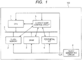
- Fig. 1 schematically depicts the semiconductor device 100 concerned with the first embodiment.
- the semiconductor device 100 includes a CPU (Central Processing Unit) 1, a flash memory 2, an SRAM (Static Random Access Memory) 3, a peripheral I/O (Input/Output) 4, a current jump control circuit 5, and a clock generating circuit 6.
- CPU Central Processing Unit
- SRAM Static Random Access Memory
- I/O Input/Output
- the CPU 1, flash memory 2, SRAM 3, and peripheral I/O 4 are configured to be able to send and receive data to/from one another via a bus 7.
- the CPU 1 performs calculation based on a program and data read in from the flash memory 2 and SRAM 3 or a signal received from the peripheral I/O 4. Also, the CPU 1 can write a result of calculation to the flash memory 2 and SRAM 3 or output it to the peripheral I/O 4, as appropriate.
- the semiconductor device 100 is equipped with the flash memory 2 and SRAM 3 as a memory block; needless to say, the semiconductor device may be equipped with a memory block other than the flash memory 2 and SRAM 3.
- the flash memory 2 and SRAM 3 are configured such that they can store a program and data for use in calculation by the CPU 1 and data received from the current jump control circuit 5.
- the current jump control circuit 5 predicts current that will be consumed in each block provided in the semiconductor device 100 and controls operation of each block based on a result of the prediction.
- the current jump control circuit 5 is provided as a chip specialized for control of a current jump independently of the CPU 1. Therefore, the current jump control circuit 5 performs processing for current jump control, so that an increase in the load of the CPU 1 can be prevented and, besides, the processing for current jump control can be carried out at high speed by using the dedicated circuit.
- Fig. 2 schematically depicts a configuration of the current jump control circuit 5.
- the current jump control circuit 5 includes a monitoring circuit 11, a decision circuit 12, a storage unit 13, and a current control circuit 14.
- the monitoring circuit 11 monitors control signals internal to the flash memory 2, SRAM 3, and peripheral I/O 4 and notifies the decision circuit 12 of a monitoring result MON.
- the decision circuit 12 decides whether or not a current jump occurs according to the result of monitoring of control signals internal to each block and outputs a detection signal DET.
- parameters are stored: various parameters P1 that are used when the decision circuit 12 decides whether or not a current jump occurs and various parameters P2 that are used for the current control circuit 14 to control operation of each block.
- the current control circuit 14 controls operation of each block, based on the detection signal DET of a current jump occurring, when decided by the decision circuit 12.
- the clock generating circuit 6 supplies a clock signal CLK to the blocks within the semiconductor device 100: i.e., the CPU 1, flash memory 2, SRAM 3, peripheral I/O 4, and current jump control circuit 5.
- FIG. 3 depicts coupling relations between the current jump control circuit 5 and each block.
- the CPU 1 includes a multiplication control unit 1A, a multiplier 1B, an AND circuit 1C, and an OR circuit 1D.
- the multiplication control unit 1A and the current control circuit 14 are coupled to one input of the AND circuit 1C in an inverse logic manner so as to be able to output a stop signal STP_1 to the AND circuit 1C.
- the multiplication control unit 1A and the monitoring circuit 11 are coupled to the other input of the AND circuit 1C so that the multiplication control unit 1A is able to output a clock enable signal CEN_1 to the AND circuit 1C and the monitoring circuit 11 is able to monitor the clock enable signal CEN_1.
- Output of the AND circuit 1C is coupled to one input of the OR circuit 1D.
- the current control circuit 14 is coupled to the other input of the OR circuit 1D so as to be able to output a forced more activation signal FORCE_1 to the OR circuit 1D.
- Output of the OR circuit 1D is coupled to the multiplier 1B.
- the CPU 1 by supplying the CPU 1 with "0" as the stop signal STP_1 and “1" as the clock enable signal CEN_1, the CPU 1 will be more activated.
- the CPU 1 by supplying the CPU 1 with "1" as the stop signal STP_1, the CPU 1 can be deactivated forcedly.
- the CPU 1 by supplying the CPU 1 with "1" as the forced more activation signal FORCE_1, the CPU 1 can be more activated forcedly.
- a program that predefines calculations or the like to be executed when the CPU 1 is more activated forcedly may be preconfigured and the CPU 1 may execute the program when it is more activated forcedly.
- the flash memory 2 includes a flash interface (I/F) 2A, a flash macro 2B, an AND circuit 2C, and an OR circuit 2D.
- the flash I/F 2A and the current control circuit 14 are coupled to one input of the AND circuit 2C in an inverse logic manner so as to be able to output a stop signal STP_2 to the AND circuit 2C.
- the flash I/F 2A and the monitoring circuit 11 are coupled to the other input of the AND circuit 2C so that the flash I/F 2A is able to output a clock enable signal CEN_2 to the AND circuit 2C and the monitoring circuit 11 is able to monitor the clock enable signal CEN_2.
- Output of the AND circuit 2C is coupled to one input of the OR circuit 2D.
- the current control circuit 14 is coupled to the other input of the OR circuit 2D so as to be able to output a forced more activation signal FORCE_2 to the OR circuit 2D.
- Output of the OR circuit 2D is coupled to the flash macro 2B.
- the flash memory 2 will be more activated.
- the flash memory 2 can be deactivated forcedly.
- the flash memory 2 can be more activated forcedly.
- forcedly more activating the flash memory may be implemented by, for example, idly reading the flash memory when it is more activated forcedly.
- the SRAM 3 includes an SRAM interface (I/F) 3A, an SRAM macro 3B, an AND circuit 3C, an OR circuit 3D, and an AND circuit 3E.
- the SRAM I/F 3A and the current control circuit 14 are coupled to one input of the AND circuit 3C in an inverse logic manner so as to be able to output a stop signal STP_3 to the AND circuit 3C.
- the SRAM I/F 3A and the monitoring circuit 11 are coupled to the other input of the AND circuit 3C so that the SRAM I/F 3A is able to output a clock enable signal CEN_3 to the AND circuit 3C and the monitoring circuit 11 is able to monitor the clock enable signal CEN_3.
- Output of the AND circuit 3C is coupled to one input of the OR circuit 3D.
- Output of the OR circuit 3D is coupled to the SRAM macro 3B.
- the current control circuit 14 is coupled to the other input of the OR circuit 3D and coupled to one input of the AND circuit 3E in an inverse logic manner so as to be able to output a forced more activation signal FORCE_3 to the OR circuit 3D and the AND circuit 3E.
- the SRAM I/F 3A and the monitoring circuit 11 are coupled to the other input of the AND circuit 3E so that the SARM I/F 3A is able to output a write enable signal WEN_3 to the AND circuit 3E and the monitoring circuit 11 is able to monitor the write enable signal WEN_3.
- Output of the AND circuit 3E is coupled to the SRAM macro 3B.
- the SRAM 3 For example, by supplying the SRAM 3 with "0" as the stop signal STP_3 and “1" as the clock enable signal CEN_3, the SRAM 3 will be more activated. On the other hand, by supplying the SRAM 3 with "1" as the stop signal STP_3, the SRAM 3 can be deactivated forcedly. Besides, by supplying the SARM 3 with "1" as the forced more activation signal FORCE_3, the SRAM 3 can be more activated forcedly even when the write enable signal WEN_3 is "0" and the stop signal STP3 is "1". In this case, forcedly more activating the SRAM may be implemented by, for example, idly reading the SRAM when it is more activated forcedly.
- the peripheral I/O 4 includes a peripheral circuit control unit 4A, a peripheral circuit 4B, an AND circuit 4C, and an OR circuit 4D.
- the peripheral circuit control unit 4A and the current control circuit 14 are coupled to one input of the AND circuit 4C in an inverse logic manner so as to be able to output a stop signal STP_4 to the AND circuit 4C.
- the peripheral circuit control unit 4A and the monitoring circuit 11 are coupled to the other input of the AND circuit 4C so that the peripheral circuit control unit 4A is able to output a clock enable signal CEN_4 to the AND circuit 4C and the monitoring circuit 11 is able to monitor the clock enable signal CEN_4.
- Output of the AND circuit 4C is coupled to one input of the OR circuit 4D.
- the current control circuit 14 is coupled to the other input of the OR circuit 4D so as to be able to output a forced more activation signal FORCE_4 to the OR circuit 4D.
- Output of the OR circuit 4D is coupled to the peripheral circuit 4B.
- peripheral I/O 4 For example, by supplying the peripheral I/O 4 with "0" as the stop signal STP_4 and “1" as the clock enable signal CEN_4, the peripheral I/O 4 will be more activated. On the other hand, by supplying the peripheral I/O 4 with "1" as the stop signal STP_4, the peripheral I/O 4 can be deactivated forcedly. Besides, by supplying the peripheral I/O 4 with "1" as the forced more activation signal FORCE_4, the peripheral I/O 4 can be more activated forcedly. In this case, for example, what operation the peripheral I/O 4 will perform when it is more activated forcedly may be predefined according to type of the peripheral I/O.
- Fig. 4 is a flowchart illustrating a current jump control operation of the semiconductor device 100 concerned with the first embodiment.
- Fig. 5 is a state transition diagram during the current jump control operation of the semiconductor device 100 concerned with the first embodiment.
- the monitoring circuit 11 monitors the clock enable signals CEN_1 to CEN_4 for the CPU 1, flash memory 2, SRAM 3, and peripheral I/O 4 and the write enable signal WEN_3 for the SRAM 3 ("STABLE" in Fig. 5 ).
- the decision circuit 12 calculates predicted values of a total amount of consumption electricity in the CPU 1, flash memory 2, SRAM 3, and peripheral I/O 4, based on results of monitoring of the clock enable signals CEN_1 to CEN_4 and the write enable signal WEN_3 at different timings.
- the decision circuit calculates a predicted value PVn which is calculated at cycle n (where n is an integer) (which is also referred to as a fist predicated value of consumption current) and a predicted value PVm which is calculated at cycle m (where m is an integer equal to or larger than n + 1) later than cycle n (which is also referred to as a second predicted value of consumption current).
- Calculating a predicted value can be, for example, performed as follows.
- a predicted value of current consumption of the flash memory 2 is estimated to be 4.0 mA/cycle.
- Predicted values of current consumption in the respective blocks whose operations are controlled by the clock enable signals CEN_1 to CEN 4 and the write enable signal WEN_3 for the SRAM 3 are stored into the storage unit 13 as parameters. According to results of monitoring of the clock enable signals CEN_1 to CEN 4 and the write enable signal WEN_3 for the SRAM 3, by referring to the parameters in the storage unit 13, the decision circuit 12 can read out predicted values of consumption current in the respective blocks and add these values.
- the parameters representing the predicted values of current consumption in the respective blocks can be calculated by a current simulation; these parameters may be static or may be parameters that can be rewritten externally.
- the decision circuit 12 detects a current jump, based on the predicted values of the total amount of consumption current calculated per clock cycle. In particular, relative to the predicted value PVn calculated at cycle n, the decision circuit detects if the predicted value PVm calculated at cycle m has increased by more than a given value (a threshold JUMP_UP_MAX which is also referred to as a first value) or has decreased by more than a given value (a threshold JUMP_DWN_MAX which is also referred to as a second value) . That is, the decision circuit detects if PVm - PVn > JUMP_UP_MAX or if PVn - PVm > JUMP_DWN_MAX. The decision circuit 12 outputs a detection signal DET indicating that a current jump has occurred.
- a threshold JUMP_UP_MAX which is also referred to as a first value
- a threshold JUMP_DWN_MAX which is also referred to as a second value
- the threshold JUMP_UP_MAX and the threshold JUMP_DWN_MAX are stored into, e.g., the storage unit 13 as parameters for use for decision.
- the threshold JUMP_UP_MAX and the threshold JUMP_DWN_MAX which are stored in the storage unit 13 mat be static or may be parameters that can be rewritten externally.
- the threshold JUMP_UP_MAX and the threshold JUMP_DWN_MAX may be predefined values.
- the decision circuit 12 may average predicted values of consumption current over a plurality of clock cycles and compare the resultant average predicted value with an average predicted value over another period. For example, the decision circuit may calculate a first average predicted value over successive five clock cycles, then, calculate a second average predicted value over subsequent successive five clock cycles, and compare the first and second average predicted values to detect a current jump.
- the decision circuit 12 may calculate a predicted value of consumption current depending on the frequency of the clock signal CLK.
- the current control circuit 14 When the current control circuit 14 has been notified of current jump occurrence by the detection signal DET, it outputs the stop signal or forced more activation signal to a subset or all of the CPU 1, flash memory 2, SRAM 3, and peripheral I/O 4.
- the current control circuit 14 outputs a subset or all of stop signals STP_1 to STP_4 and performs control to make the predicted value of consumption current smaller than the given value. This corresponds to a state transition from "STABLE” to "DOWN” in Fig. 5 .
- the current control circuit 14 outputs a subset or all of forced more activation signals FORCE_1 to FORCE_4 and performs control to make the predicted value of consumption current larger than the given value. This corresponds to a state transition from "STABLE" to "UP” in Fig. 5 .
- a possible way of increasing the consumption current is, for example, a dummy read operation of the flash memory 2 and SRAM 3, that is, reading is performed, but values that have been read are not used. Additionally, increasing the current is also possible in such a way that a dummy circuit which is not used in normal operation is provided in each block and the dummy circuit is activated.
- a block or blocks that should be deactivated or more activated forcedly among the CPU 1, flash memory 2, SRAM 3, and peripheral I/O 4 may be selected by priority order or predetermined. Priority order of blocks that should be deactivated or more activated forcedly may be stored into, e.g., the storage unit 13 and the current control circuit 14 may read out it from the storage unit 13.
- the CPU 1 when the CPU 1 is executing a process that cannot be halted, forced deactivation of the CPU 1 should be avoided and other blocks, such as the SRAM, which will not suffer from an error or the like even when deactivated forcedly, may be deactivated forcedly.
- the flash memory 2 and the SRAM 3 may be deactivated forcedly on a preferential basis. In this case, a response to access from the CPU 1 of the flash memory 2 and the SRAM 3 is delayed, but the CPU 1 can read out desired data after recovery to the active state of the flash memory 2 and the SRAM 3.
- the forced deactivation or forced more activation state is maintained only for a given period of time to restrain the influence of a voltage fluctuation due to the current jump.
- a given period of time for which the forced deactivation or forced more activation state should be maintained is calculated by circuit simulation or the like and stored in advance into the storage unit 13 as a parameter, so that the current control circuit 14 can read out it. Carrying out forced deactivation or forced more activation and maintaining it for a given period of time correspond to "HOLD" (Standby 1) in Fig. 5 .
- an internal voltage V of the semiconductor device 100 i.e., its power supply voltage is monitored.
- Monitoring the internal voltage V can be, for example, performed by the current control circuit 14.
- the current control circuit monitors if the internal voltage V remains stable within a given range for a predetermined period.
- Monitoring the internal voltage can be, for example, performed by the current control circuit 14.
- a predetermined period for which the internal voltage should be monitored is stored in advance into the storage unit 13 as a parameter, so that the current control circuit 14 can read out it.
- the forced deactivation or forced more activation state is cancelled and a recovery is made to signal monitoring by the monitoring circuit 11, followed by monitoring whether or not a current jump occurs.
- Monitoring the internal voltage and maintaining and cancelling the more activation state correspond to "V STABLE" (Standby 2) in Fig. 5 .
- consumption current is controlled by detecting a current jump occurrence and carrying out forced deactivation or forced more activation of a block or blocks; in consequence, a fluctuation of internal voltage can be restrained.
- Fig. 6 gives a graphic representation of forced deactivation when a current jump has occurred.
- the left part plots a graph for a case where forced deactivation was not carried out upon the occurrence of a current jump, as a comparison example, and the right part plots a graph for a case forced deactivation was carried out upon the occurrence of a current jump according to the present embodiment.
- an abrupt sharp rise of current occurs at time 10 ⁇ sec, resulting in that the internal voltage becomes lower than a lower limit value MIN of a guaranteed voltage. In this case, consequently, malfunction could occur in the semiconductor device.
- the current jump control circuit 5 detects a current jump occurrence and forcedly deactivates a block or blocks allowed to be deactivated. It can be understood that this makes a voltage drop less than in the comparison example and the internal voltage falls in a range higher than the lower limit value MIN of the guaranteed voltage.
- FIG. 7 schematically depicts a configuration of a principal part of the semiconductor device 200 concerned with the second embodiment.
- the semiconductor device 200 is configured such that parameters for use for control of a current jump stored in a register in a storage unit 13 can be updated automatically by control of an external control circuit 1000.
- the semiconductor device 200 has a configuration in which a ROM (Read Only Memory) 8 is added to the semiconductor device 100.
- the ROM 8 is able to send and receive data to/from other blocks, such as the CPU 1, within the semiconductor device 200 via a bus 7 (not depicted) .
- the semiconductor device 200 is able to send and receive signals and data to/from the external control circuit 1000 and a watchdog timer (WDT) 1001 via an external bus 1002.
- WDT watchdog timer
- FIG. 8 is a flowchart illustrating the method for automatically updating parameters for use for control of a current jump in the semiconductor device 200 concerned with the second embodiment.
- the external control circuit 1000 directs semiconductor device 200 to automatically update parameters for use for control of a current jump by giving a control signal to the semiconductor device 200 via the external bus 1002. Thereby, the CPU 1 initializes the parameters stored in the ROM 8. Also, the external control circuit 1000 starts up the WDT 1001.
- the CPU 1 updates the parameters stored in the ROM 8 by executing, e.g., a given program.
- a given program which is used by the CPU 1 is stored in advance into, e.g., the ROM 8 and the CPU 1 may read out it as required.
- the CPU 1 reads out updated parameters and writes them into a register in the storage unit 13 of the current jump control circuit 13 as the parameters for use for control of a current jump.
- the CPU 1 executes a test program to test a current jump control operation.
- This test program causes the semiconductor device 200 to execute a process in which a current jump will occur or a current jump is likely to occur.
- the CPU 1 monitors if the internal voltage of the semiconductor device 200 falls within a desired range. And now, in the present embodiment, if the internal voltage of the semiconductor device 200 falls within the desired range, a stop signal is output from the semiconductor device 200 to the WDT 1001.
- the WDT 1001 If the internal voltage of the semiconductor device 200 deviates from the desired range, the WDT 1001 outputs a reset signal RES to the semiconductor device 200 after elapse of a given period from its startup. Thereby, the CPU 1 returns to step S22, updates the parameters in the ROM 8 again, and performs processing at step S23 and subsequent.
- the stop signal is output from the semiconductor device 200 to the WDT 1001. In consequence, the WDT1 stops and the operation of updating the parameters terminates.
- parameters for use for control of a current jump can be set to prevent the internal voltage of the semiconductor device from deviating from a given range due to a current jump caused to occur by the test program.
- Automatically updating parameters for use for control of a current jump can be performed, for example, by giving a directive to the semiconductor device 200 when it is inspected for shipment, when it is booted, or after it is mounted in equipment or the like. Thereby, it is possible to correct variation attributed to semiconductor device manufacturing errors and depending on semiconductor device usage environment and restrain an internal voltage fluctuation due to a current jump more reliably.
- the CPU 1, flash memory 2, SRAM 3, and peripheral I/O 4 are used as blocks which are deactivated or more activated forcedly. This is only for illustrative purposes. Blocks of various processors, controllers, etc. other than these blocks may be deactivated or more activated forcedly.
- a special-purpose block that has a small area and consumes more current may be provided in advance in the semiconductor device and the amount of consumption electricity may be augmented by more activating this block forcedly.
- the operating frequency of a block which is put into operation may be decreased forcedly. This enables it to reduce the consumption current of the block.
- the operating frequency of a block which is put into operation may be increased forcedly. This enables it to augment the consumption current of the block.
- a standby time that is relevant to step S14 in Fig. 4 may differ for each block.
Abstract
Disclosed is a semiconductor device in which an internal voltage fluctuation when a current jump occurs is restrained. The semiconductor device includes a plurality of blocks, each of which performs a given operation, and a current jump control circuit. The current jump control circuit monitors control signals in each of the blocks and calculates predicted values of consumption current of the blocks, based on results of monitoring at different timings, thereby controlling a fluctuation of consumption current of the blocks. The current jump control circuit controls operation of a subset or all of the blocks, if an increase of a predicted value of consumption current of the blocks is larger than a first value or a decrease of the predicted value is larger than a second value.
Description
- The disclosure of Japanese Patent Application No.
2017-246335 filed on December 22, 2017 - The present invention relates to a semiconductor device and a semiconductor device control method.
- Because of more microfabrication processes in manufacturing semiconductor devices, there have been a decrease in chip area and a reduction in parasitic capacitance. On the other hand, there is no reduction in consumption current, despite the decrease in area. Consequently, when an abrupt sharp increase or decrease of consumption current, namely, a so-called current jump occurs, an abrupt sharp rise or fall of an internal voltage occurs and a problem arises in which a voltage value deviates from a guaranteed voltage range.
- And now, consumption current includes a dynamic consumption current that increases or decreases by more activation or deactivat1ion of each part of a chip and a static current such as a leak current that less increases or decreases by chip operation. Herein, we focus on increase or decrease in the dynamic power consumption.
- To cope with the above problem, proposed is a method for restraining the occurrence of a current jump by controlling switchover of a clock frequency (Patent Document 1). Generally, the increase or decrease of consumption current is liable to occur upon the switchover of a clock frequency. Therefore, this method prevents the abrupt sharp increase and decrease of voltage by changing a clock frequency rather slowly without switching over a clock frequency quickly.
- Japanese Unexamined Patent Application Publication No.
2005-249526 - As described above, an abrupt sharp rise or fall of an internal voltage occurs, attributed to an abrupt sharp increase or decrease of consumption current. In fact, switchover of a clock signal is only one factor of causing an abrupt sharp rise or fall of an internal voltage. Hence, the method concerned with
Patent Document 1 is essentially incapable of preventing a current jump due to a cause other than switchover of a clock signal. - Other problems and novel features will become apparent from the description in the present specification and the accompanying drawings.
- A semiconductor device concerned with one embodiment includes a plurality of blocks, each of which performs a given operation, and a control circuit which monitors control signals in each of the blocks and calculates predicted values of consumption current of the blocks, based on results of monitoring at different timings, thereby controlling a fluctuation of consumption current of the blocks. The control circuit controls a subset or all of the blocks to decrease consumption current, if an increase of a predicted value of the consumption current is larger than a first value, and controls a subset or all of the blocks to increase consumption current, if a decrease of a predicted value of the consumption current is larger than a second value.
- A semiconductor device control method concerned with one embodiment includes: monitoring control signals in each of a plurality of blocks, each of which performs a given operation; calculating predicted values of consumption current of the blocks, based on results of monitoring at different timings; controlling a subset or all of the blocks to decrease consumption current, if an increase of a predicted value of consumption current of the blocks is larger than a first value; and controlling a subset or all of the blocks to increase consumption current, if a decrease of a predicted value of consumption current of the blocks is larger than a second value.
- According to one embodiment, it is possible to restrain an internal voltage fluctuation when a current jump occurs in a semiconductor device.
-
-
Fig. 1 is a diagram schematically depicting a configuration of a semiconductor device concerned with a first embodiment. -
Fig. 2 is a diagram schematically depicting a configuration of a current jump control circuit. -
Fig. 3 is a diagram depicting coupling relations between the current jump control circuit and each block. -
Fig. 4 is a flowchart illustrating a current jump control operation of the semiconductor device concerned with the first embodiment. -
Fig. 5 is a state transition diagram during the current jump control operation of the semiconductor device concerned with the first embodiment. -
Fig. 6 is a diagram giving a graphic representation of forced deactivation when a current jump has occurred. -
Fig. 7 is a diagram schematically depicting a configuration of a principal part of a semiconductor device concerned with a second embodiment. -
Fig. 8 is a flowchart illustrating a method for automatically updating parameters for use for control of a current jump in the semiconductor device concerned with the second embodiment. - In the following, embodiments of the present invention will be described with reference to the drawings. In the respective drawings, identical elements are assigned identical reference designators and their duplicative description is omitted, as appropriate.
- A
semiconductor device 100 concerned with a first embodiment is described. Thesemiconductor device 100 is configured to enable preventing a total value of consumption currents of all blocks provided in the semiconductor device and controlling operation of the blocks according to a predicted value. And now, consumption current includes a dynamic consumption current that increases or decreases by more activation or deactivation of each part of a chip and a static current such as a leak current that less increases or decreases by chip operation. Herein, we focus on increase or decrease in the dynamic power consumption. -
Fig. 1 schematically depicts thesemiconductor device 100 concerned with the first embodiment. Thesemiconductor device 100 includes a CPU (Central Processing Unit) 1, aflash memory 2, an SRAM (Static Random Access Memory) 3, a peripheral I/O (Input/Output) 4, a currentjump control circuit 5, and aclock generating circuit 6. - The
CPU 1,flash memory 2,SRAM 3, and peripheral I/O 4 are configured to be able to send and receive data to/from one another via abus 7. - The
CPU 1 performs calculation based on a program and data read in from theflash memory 2 andSRAM 3 or a signal received from the peripheral I/O 4. Also, theCPU 1 can write a result of calculation to theflash memory 2 andSRAM 3 or output it to the peripheral I/O 4, as appropriate. Although thesemiconductor device 100 is equipped with theflash memory 2 and SRAM 3 as a memory block; needless to say, the semiconductor device may be equipped with a memory block other than theflash memory 2 and SRAM 3. - The
flash memory 2 and SRAM 3 are configured such that they can store a program and data for use in calculation by theCPU 1 and data received from the currentjump control circuit 5. - The current
jump control circuit 5 predicts current that will be consumed in each block provided in thesemiconductor device 100 and controls operation of each block based on a result of the prediction. In the present embodiment, the currentjump control circuit 5 is provided as a chip specialized for control of a current jump independently of theCPU 1. Therefore, the currentjump control circuit 5 performs processing for current jump control, so that an increase in the load of theCPU 1 can be prevented and, besides, the processing for current jump control can be carried out at high speed by using the dedicated circuit. - Now, a description is provided on how the current
jump control circuit 5 is configured.Fig. 2 schematically depicts a configuration of the currentjump control circuit 5. The currentjump control circuit 5 includes amonitoring circuit 11, adecision circuit 12, astorage unit 13, and acurrent control circuit 14. - The
monitoring circuit 11 monitors control signals internal to theflash memory 2,SRAM 3, and peripheral I/O 4 and notifies thedecision circuit 12 of a monitoring result MON. - The
decision circuit 12 decides whether or not a current jump occurs according to the result of monitoring of control signals internal to each block and outputs a detection signal DET. - In the
storage unit 13, parameters are stored: various parameters P1 that are used when thedecision circuit 12 decides whether or not a current jump occurs and various parameters P2 that are used for thecurrent control circuit 14 to control operation of each block. - The
current control circuit 14 controls operation of each block, based on the detection signal DET of a current jump occurring, when decided by thedecision circuit 12. - The clock generating
circuit 6 supplies a clock signal CLK to the blocks within the semiconductor device 100: i.e., theCPU 1,flash memory 2,SRAM 3, peripheral I/O 4, and currentjump control circuit 5. - Then, a description is provided on coupling relations between the current
jump control circuit 5 and each block.Fig. 3 depicts coupling relations between the currentjump control circuit 5 and each block. - The
CPU 1 includes amultiplication control unit 1A, amultiplier 1B, anAND circuit 1C, and anOR circuit 1D. Themultiplication control unit 1A and thecurrent control circuit 14 are coupled to one input of theAND circuit 1C in an inverse logic manner so as to be able to output a stop signal STP_1 to theAND circuit 1C. Themultiplication control unit 1A and themonitoring circuit 11 are coupled to the other input of theAND circuit 1C so that themultiplication control unit 1A is able to output a clock enable signal CEN_1 to theAND circuit 1C and themonitoring circuit 11 is able to monitor the clock enable signal CEN_1. Output of theAND circuit 1C is coupled to one input of theOR circuit 1D. Thecurrent control circuit 14 is coupled to the other input of theOR circuit 1D so as to be able to output a forced more activation signal FORCE_1 to theOR circuit 1D. Output of theOR circuit 1D is coupled to themultiplier 1B. - For example, by supplying the
CPU 1 with "0" as the stop signal STP_1 and "1" as the clock enable signal CEN_1, theCPU 1 will be more activated. On the other hand, by supplying theCPU 1 with "1" as the stop signal STP_1, theCPU 1 can be deactivated forcedly. Besides, by supplying theCPU 1 with "1" as the forced more activation signal FORCE_1, theCPU 1 can be more activated forcedly. In this case, for example, a program that predefines calculations or the like to be executed when theCPU 1 is more activated forcedly may be preconfigured and theCPU 1 may execute the program when it is more activated forcedly. - The
flash memory 2 includes a flash interface (I/F) 2A, aflash macro 2B, an ANDcircuit 2C, and anOR circuit 2D. The flash I/F 2A and thecurrent control circuit 14 are coupled to one input of the ANDcircuit 2C in an inverse logic manner so as to be able to output a stop signal STP_2 to the ANDcircuit 2C. The flash I/F 2A and themonitoring circuit 11 are coupled to the other input of the ANDcircuit 2C so that the flash I/F 2A is able to output a clock enable signal CEN_2 to the ANDcircuit 2C and themonitoring circuit 11 is able to monitor the clock enable signal CEN_2. Output of the ANDcircuit 2C is coupled to one input of theOR circuit 2D. Thecurrent control circuit 14 is coupled to the other input of theOR circuit 2D so as to be able to output a forced more activation signal FORCE_2 to theOR circuit 2D. Output of theOR circuit 2D is coupled to theflash macro 2B. - For example, by supplying the
flash memory 2 with "0" as the stop signal STP_2 and "1" as the clock enable signal CEN_2, theflash memory 2 will be more activated. On the other hand, by supplying theflash memory 2 with "1" as the stop signal STP_2, theflash memory 2 can be deactivated forcedly. Besides, by supplying theflash memory 2 with "1" as the forced more activation signal FORCE_2, theflash memory 2 can be more activated forcedly. In this case, forcedly more activating the flash memory may be implemented by, for example, idly reading the flash memory when it is more activated forcedly. - The
SRAM 3 includes an SRAM interface (I/F) 3A, anSRAM macro 3B, an ANDcircuit 3C, anOR circuit 3D, and an ANDcircuit 3E. The SRAM I/F 3A and thecurrent control circuit 14 are coupled to one input of the ANDcircuit 3C in an inverse logic manner so as to be able to output a stop signal STP_3 to the ANDcircuit 3C. The SRAM I/F 3A and themonitoring circuit 11 are coupled to the other input of the ANDcircuit 3C so that the SRAM I/F 3A is able to output a clock enable signal CEN_3 to the ANDcircuit 3C and themonitoring circuit 11 is able to monitor the clock enable signal CEN_3. Output of the ANDcircuit 3C is coupled to one input of theOR circuit 3D. Output of theOR circuit 3D is coupled to the SRAM macro 3B. Thecurrent control circuit 14 is coupled to the other input of theOR circuit 3D and coupled to one input of the ANDcircuit 3E in an inverse logic manner so as to be able to output a forced more activation signal FORCE_3 to theOR circuit 3D and the ANDcircuit 3E. The SRAM I/F 3A and themonitoring circuit 11 are coupled to the other input of the ANDcircuit 3E so that the SARM I/F 3A is able to output a write enable signal WEN_3 to the ANDcircuit 3E and themonitoring circuit 11 is able to monitor the write enable signal WEN_3. Output of the ANDcircuit 3E is coupled to the SRAM macro 3B. - For example, by supplying the
SRAM 3 with "0" as the stop signal STP_3 and "1" as the clock enable signal CEN_3, theSRAM 3 will be more activated. On the other hand, by supplying theSRAM 3 with "1" as the stop signal STP_3, theSRAM 3 can be deactivated forcedly. Besides, by supplying theSARM 3 with "1" as the forced more activation signal FORCE_3, theSRAM 3 can be more activated forcedly even when the write enable signal WEN_3 is "0" and the stop signal STP3 is "1". In this case, forcedly more activating the SRAM may be implemented by, for example, idly reading the SRAM when it is more activated forcedly. - The peripheral I/
O 4 includes a peripheralcircuit control unit 4A, aperipheral circuit 4B, an ANDcircuit 4C, and anOR circuit 4D. The peripheralcircuit control unit 4A and thecurrent control circuit 14 are coupled to one input of the ANDcircuit 4C in an inverse logic manner so as to be able to output a stop signal STP_4 to the ANDcircuit 4C. The peripheralcircuit control unit 4A and themonitoring circuit 11 are coupled to the other input of the ANDcircuit 4C so that the peripheralcircuit control unit 4A is able to output a clock enable signal CEN_4 to the ANDcircuit 4C and themonitoring circuit 11 is able to monitor the clock enable signal CEN_4. Output of the ANDcircuit 4C is coupled to one input of theOR circuit 4D. Thecurrent control circuit 14 is coupled to the other input of theOR circuit 4D so as to be able to output a forced more activation signal FORCE_4 to theOR circuit 4D. Output of theOR circuit 4D is coupled to theperipheral circuit 4B. - For example, by supplying the peripheral I/
O 4 with "0" as the stop signal STP_4 and "1" as the clock enable signal CEN_4, the peripheral I/O 4 will be more activated. On the other hand, by supplying the peripheral I/O 4 with "1" as the stop signal STP_4, the peripheral I/O 4 can be deactivated forcedly. Besides, by supplying the peripheral I/O 4 with "1" as the forced more activation signal FORCE_4, the peripheral I/O 4 can be more activated forcedly. In this case, for example, what operation the peripheral I/O 4 will perform when it is more activated forcedly may be predefined according to type of the peripheral I/O. - Then, a description is provided on operation of the current
jump control circuit 5.Fig. 4 is a flowchart illustrating a current jump control operation of thesemiconductor device 100 concerned with the first embodiment.Fig. 5 is a state transition diagram during the current jump control operation of thesemiconductor device 100 concerned with the first embodiment. - As noted previously, the
monitoring circuit 11 monitors the clock enable signals CEN_1 to CEN_4 for theCPU 1,flash memory 2,SRAM 3, and peripheral I/O 4 and the write enable signal WEN_3 for the SRAM 3 ("STABLE" inFig. 5 ). - The
decision circuit 12 calculates predicted values of a total amount of consumption electricity in theCPU 1,flash memory 2,SRAM 3, and peripheral I/O 4, based on results of monitoring of the clock enable signals CEN_1 to CEN_4 and the write enable signal WEN_3 at different timings. In particular, the decision circuit calculates a predicted value PVn which is calculated at cycle n (where n is an integer) (which is also referred to as a fist predicated value of consumption current) and a predicted value PVm which is calculated at cycle m (where m is an integer equal to or larger than n + 1) later than cycle n (which is also referred to as a second predicted value of consumption current). - Calculating a predicted value can be, for example, performed as follows. The
decision circuit 12 calculates consumption current, for example, referring to monitoring results at the rising edge of a clock signal CLK. For example, in a write state of theSRAM 3, i.e., when the signals are such that STP_3 = 0, CEN_3 = 1, and WEN_3 = 1, a predicted value of current consumption of theSRAM 3 is estimated to be 1.5 mA/cycle. Besides, in a read state of theSRAM 3, i.e., when the signals are such that STP_3 = 0, CEN_3 = 1, and WEN_3 = 0, a predicted value of current consumption of theSRAM 3 is estimated to be 1.0 mA/cycle. - Besides, for example, in a read state of the
flash memory 2, i.e., when the signals are such that STP_2 = 0 and CEN_2 = 1, a predicted value of current consumption of theflash memory 2 is estimated to be 4.0 mA/cycle. Furthermore, for example, in a calculation execution state of theCPU 1, i.e., when the signals are such that STP_1 = 0 and CEN_1 = 1, a predicted value of current consumption of theCPU 1 is estimated to be 0.5 mA/cycle. - Predicted values of current consumption in the respective blocks whose operations are controlled by the clock enable signals CEN_1 to
CEN 4 and the write enable signal WEN_3 for theSRAM 3 are stored into thestorage unit 13 as parameters. According to results of monitoring of the clock enable signals CEN_1 toCEN 4 and the write enable signal WEN_3 for theSRAM 3, by referring to the parameters in thestorage unit 13, thedecision circuit 12 can read out predicted values of consumption current in the respective blocks and add these values. - Here, the parameters representing the predicted values of current consumption in the respective blocks can be calculated by a current simulation; these parameters may be static or may be parameters that can be rewritten externally.
- The
decision circuit 12 detects a current jump, based on the predicted values of the total amount of consumption current calculated per clock cycle. In particular, relative to the predicted value PVn calculated at cycle n, the decision circuit detects if the predicted value PVm calculated at cycle m has increased by more than a given value (a threshold JUMP_UP_MAX which is also referred to as a first value) or has decreased by more than a given value (a threshold JUMP_DWN_MAX which is also referred to as a second value) . That is, the decision circuit detects if PVm - PVn > JUMP_UP_MAX or if PVn - PVm > JUMP_DWN_MAX. Thedecision circuit 12 outputs a detection signal DET indicating that a current jump has occurred. - Here, the threshold JUMP_UP_MAX and the threshold JUMP_DWN_MAX are stored into, e.g., the
storage unit 13 as parameters for use for decision. The threshold JUMP_UP_MAX and the threshold JUMP_DWN_MAX which are stored in thestorage unit 13 mat be static or may be parameters that can be rewritten externally. - The threshold JUMP_UP_MAX and the threshold JUMP_DWN_MAX may be predefined values.
- The
decision circuit 12 may average predicted values of consumption current over a plurality of clock cycles and compare the resultant average predicted value with an average predicted value over another period. For example, the decision circuit may calculate a first average predicted value over successive five clock cycles, then, calculate a second average predicted value over subsequent successive five clock cycles, and compare the first and second average predicted values to detect a current jump. - Furthermore, the
decision circuit 12 may calculate a predicted value of consumption current depending on the frequency of the clock signal CLK. In this case, given that a predicted value E1 with the clock signal frequency being f1 is converted to a predicted value W2 with the clock signal frequency being f1 being f2, W1 may be divided by a frequency division ratio (f1/f2) (W2 = W1/(f1/f2). - When the
current control circuit 14 has been notified of current jump occurrence by the detection signal DET, it outputs the stop signal or forced more activation signal to a subset or all of theCPU 1,flash memory 2,SRAM 3, and peripheral I/O 4. - In fact, if a steep increase in current has been detected, the
current control circuit 14 outputs a subset or all of stop signals STP_1 to STP_4 and performs control to make the predicted value of consumption current smaller than the given value. This corresponds to a state transition from "STABLE" to "DOWN" inFig. 5 . - If a steep decrease in current has been detected, the
current control circuit 14 outputs a subset or all of forced more activation signals FORCE_1 to FORCE_4 and performs control to make the predicted value of consumption current larger than the given value. This corresponds to a state transition from "STABLE" to "UP" inFig. 5 . A possible way of increasing the consumption current is, for example, a dummy read operation of theflash memory 2 andSRAM 3, that is, reading is performed, but values that have been read are not used. Additionally, increasing the current is also possible in such a way that a dummy circuit which is not used in normal operation is provided in each block and the dummy circuit is activated. - A block or blocks that should be deactivated or more activated forcedly among the
CPU 1,flash memory 2,SRAM 3, and peripheral I/O 4 may be selected by priority order or predetermined. Priority order of blocks that should be deactivated or more activated forcedly may be stored into, e.g., thestorage unit 13 and thecurrent control circuit 14 may read out it from thestorage unit 13. - For instance, when the
CPU 1 is executing a process that cannot be halted, forced deactivation of theCPU 1 should be avoided and other blocks, such as the SRAM, which will not suffer from an error or the like even when deactivated forcedly, may be deactivated forcedly. Also, theflash memory 2 and theSRAM 3 may be deactivated forcedly on a preferential basis. In this case, a response to access from theCPU 1 of theflash memory 2 and theSRAM 3 is delayed, but theCPU 1 can read out desired data after recovery to the active state of theflash memory 2 and theSRAM 3. - Then, the forced deactivation or forced more activation state is maintained only for a given period of time to restrain the influence of a voltage fluctuation due to the current jump. A given period of time for which the forced deactivation or forced more activation state should be maintained is calculated by circuit simulation or the like and stored in advance into the
storage unit 13 as a parameter, so that thecurrent control circuit 14 can read out it. Carrying out forced deactivation or forced more activation and maintaining it for a given period of time correspond to "HOLD" (Standby 1) inFig. 5 . - Then, an internal voltage V of the
semiconductor device 100, i.e., its power supply voltage is monitored. Monitoring the internal voltage V can be, for example, performed by thecurrent control circuit 14. In particular, the current control circuit monitors if the internal voltage V remains stable within a given range for a predetermined period. Monitoring the internal voltage can be, for example, performed by thecurrent control circuit 14. A predetermined period for which the internal voltage should be monitored is stored in advance into thestorage unit 13 as a parameter, so that thecurrent control circuit 14 can read out it. And now, if the internal voltage V is stable, the forced deactivation or forced more activation state is cancelled and a recovery is made to signal monitoring by themonitoring circuit 11, followed by monitoring whether or not a current jump occurs. Monitoring the internal voltage and maintaining and cancelling the more activation state correspond to "V STABLE" (Standby 2) inFig. 5 . - As described hereinbefore, according to the
semiconductor device 100, consumption current is controlled by detecting a current jump occurrence and carrying out forced deactivation or forced more activation of a block or blocks; in consequence, a fluctuation of internal voltage can be restrained. - Then, we verify restraining a current jump in the
semiconductor device 100.Fig. 6 gives a graphic representation of forced deactivation when a current jump has occurred. InFig. 6 , the left part plots a graph for a case where forced deactivation was not carried out upon the occurrence of a current jump, as a comparison example, and the right part plots a graph for a case forced deactivation was carried out upon the occurrence of a current jump according to the present embodiment. As presented inFig. 6 , in the comparison example at the left, an abrupt sharp rise of current occurs attime 10 µsec, resulting in that the internal voltage becomes lower than a lower limit value MIN of a guaranteed voltage. In this case, consequently, malfunction could occur in the semiconductor device. - In contrast, according to the
semiconductor device 100, as presented at the right inFig. 6 , when an abrupt sharp rise of current has occurred attime 10 µsec, the currentjump control circuit 5 detects a current jump occurrence and forcedly deactivates a block or blocks allowed to be deactivated. It can be understood that this makes a voltage drop less than in the comparison example and the internal voltage falls in a range higher than the lower limit value MIN of the guaranteed voltage. - As described hereinbefore, according to the present configuration, by monitoring signals internal to the respective blocks of the semiconductor device and predicting consumption current, it is possible to forcedly deactivate or more activate the blocks in order to reduce the influence of an abrupt sharp fluctuation of current which might occur. In consequence, it is possible to prevent the internal voltage from deviating from a guaranteed voltage range due to a current jump.
- A
semiconductor device 200 concerned with a second embodiment is described.Fig. 7 schematically depicts a configuration of a principal part of thesemiconductor device 200 concerned with the second embodiment. Thesemiconductor device 200 is configured such that parameters for use for control of a current jump stored in a register in astorage unit 13 can be updated automatically by control of anexternal control circuit 1000. - The
semiconductor device 200 has a configuration in which a ROM (Read Only Memory) 8 is added to thesemiconductor device 100. TheROM 8 is able to send and receive data to/from other blocks, such as theCPU 1, within thesemiconductor device 200 via a bus 7 (not depicted) . Thesemiconductor device 200 is able to send and receive signals and data to/from theexternal control circuit 1000 and a watchdog timer (WDT) 1001 via anexternal bus 1002. - A description is provided about a method for automatically updating parameters for use for control of a current jump.
Fig. 8 is a flowchart illustrating the method for automatically updating parameters for use for control of a current jump in thesemiconductor device 200 concerned with the second embodiment. - The
external control circuit 1000 directssemiconductor device 200 to automatically update parameters for use for control of a current jump by giving a control signal to thesemiconductor device 200 via theexternal bus 1002. Thereby, theCPU 1 initializes the parameters stored in theROM 8. Also, theexternal control circuit 1000 starts up theWDT 1001. - The
CPU 1 updates the parameters stored in theROM 8 by executing, e.g., a given program. A given program which is used by theCPU 1 is stored in advance into, e.g., theROM 8 and theCPU 1 may read out it as required. - The
CPU 1 reads out updated parameters and writes them into a register in thestorage unit 13 of the currentjump control circuit 13 as the parameters for use for control of a current jump. - The
CPU 1 executes a test program to test a current jump control operation. This test program causes thesemiconductor device 200 to execute a process in which a current jump will occur or a current jump is likely to occur. - Upon the occurrence of a current jump and when the current jump control operation is performed by the current
jump control circuit 5, theCPU 1 monitors if the internal voltage of thesemiconductor device 200 falls within a desired range. And now, in the present embodiment, if the internal voltage of thesemiconductor device 200 falls within the desired range, a stop signal is output from thesemiconductor device 200 to theWDT 1001. - If the internal voltage of the
semiconductor device 200 deviates from the desired range, theWDT 1001 outputs a reset signal RES to thesemiconductor device 200 after elapse of a given period from its startup. Thereby, theCPU 1 returns to step S22, updates the parameters in theROM 8 again, and performs processing at step S23 and subsequent. - If the internal voltage of the
semiconductor device 200 falls within the desired range, the stop signal is output from thesemiconductor device 200 to theWDT 1001. In consequence, the WDT1 stops and the operation of updating the parameters terminates. - As will be appreciated from the foregoing, it can be understood that parameters for use for control of a current jump can be set to prevent the internal voltage of the semiconductor device from deviating from a given range due to a current jump caused to occur by the test program.
- Automatically updating parameters for use for control of a current jump according to the present embodiment can be performed, for example, by giving a directive to the
semiconductor device 200 when it is inspected for shipment, when it is booted, or after it is mounted in equipment or the like. Thereby, it is possible to correct variation attributed to semiconductor device manufacturing errors and depending on semiconductor device usage environment and restrain an internal voltage fluctuation due to a current jump more reliably. - While the invention made by the present inventors has been described specifically based on its embodiments hereinbefore, it will be appreciated that the present invention is not limited to the embodiments described previously and various modifications may be made thereto without departing from the gist of the invention. For instance, in the foregoing embodiments, the
CPU 1,flash memory 2,SRAM 3, and peripheral I/O 4 are used as blocks which are deactivated or more activated forcedly. This is only for illustrative purposes. Blocks of various processors, controllers, etc. other than these blocks may be deactivated or more activated forcedly. - Besides, a special-purpose block that has a small area and consumes more current may be provided in advance in the semiconductor device and the amount of consumption electricity may be augmented by more activating this block forcedly.
- For example, by making an arrangement to forcedly deactivate or more activate a block consuming more power on a preferential basis, restraining a current jump can be implemented by more simple control. Thereby, it becomes unnecessary to monitor blocks having a less consumption current fluctuation and the size of the current
jump control circuit 5 can be reduced. - Instead of forced deactivation, the operating frequency of a block which is put into operation may be decreased forcedly. This enables it to reduce the consumption current of the block. Instead of forced more activation, the operating frequency of a block which is put into operation may be increased forcedly. This enables it to augment the consumption current of the block.
- In the foregoing embodiments, a standby time that is relevant to step S14 in
Fig. 4 may differ for each block.
Claims (12)
- A semiconductor device comprising:a plurality of blocks, each of which performs a given operation; anda control circuit which monitors control signals in each of the blocks and calculates predicted values of consumption current of the blocks, based on results of monitoring at different timings, thereby controlling a fluctuation of consumption current of the blocks,wherein the control circuit controls a subset or all of the blocks to decrease consumption current, if an increase of a predicted value of consumption current of the blocks is larger than a first value, andwherein the control circuit controls a subset or all of the blocks to increase consumption current, if a decrease of a predicted value of consumption current of the blocks is larger than a second value.
- The semiconductor device according to claim 1,
wherein the control circuit calculates a first predicted value of consumption current,
wherein the control circuit calculates a second predicted value of consumption current after calculating the first predicted value of consumption current,
wherein the control circuit deactivates a subset or all of the blocks or decreases the operating frequency of a subset or all of the blocks, if a value obtained by subtracting the first predicted value of consumption current from the second predicted value of consumption current is larger than the first value, and
wherein the control circuit more activates a subset or all of the blocks to perform a given operation or increases the operating frequency of a subset or all of the blocks, if a value obtained by subtracting the second predicted value of consumption current from the first predicted value of consumption current is larger than the second value. - The semiconductor device according to claim 2,
wherein the first and second predicted values of consumption current are a predicted value of consumption current for a period including one or more clock cycles. - The semiconductor device according to claim 3,
wherein one of the blocks is a memory block, and
wherein one of the control signals is an enable signal for the memory block. - The semiconductor device according to claim 4,
wherein the given operation is a dummy read of the memory block. - The semiconductor device according to claim 3,
wherein at least one of the blocks comprises a dummy circuit which operates when the given operation is performed. - The semiconductor device according to claim 1,
wherein the control circuit maintains an operating state of a subset or all of the blocks for a given period time, after forcedly controlling operation of a subset or all of the blocks. - The semiconductor device according to claim 7,
wherein the control circuit monitors a power supply voltage, after maintaining an operating state of a subset or all of the blocks for a given period of time, and cancels a forced control exerted on operation of a subset or all of the blocks, if the power supply voltage remains within a given range for a given period of time. - The semiconductor device according to claim 1,
wherein the control circuit comprises a storage unit in which parameters are stored for use in calculating the predicted values of consumption current of the blocks from the results of monitoring. - The semiconductor device according to claim 9,
wherein parameters for the control circuit to control operation of a subset or all of the blocks are stored in the storage unit. - The semiconductor device according to claim 10,
wherein the parameters stored in the storage unit can be updated,
wherein a control is exerted on operation of a subset or all of the blocks, if it has been detected that a predicted value of consumption current of the blocks calculated using the parameters set in the storage unit deviates from a given current range, and
wherein the control circuit monitors a power supply voltage, retains used parameters as the parameters in the storage unit, if a fluctuation of the monitored power supply voltage falls within the given voltage range, and changes parameter values set in the storage unit, if a fluctuation of the power supply voltage is out of the given voltage range. - A semiconductor device control method comprising:monitoring control signals in each of a plurality of blocks, each of which performs a given operation;calculating predicted values of consumption current of the blocks, based on results of monitoring at different timings;controlling a subset or all of the blocks to decrease consumption current, if an increase of a predicted value of consumption current of the blocks is larger than a first value; andcontrolling a subset or all of the blocks to increase consumption current, if a decrease of a predicted value of consumption current of the blocks is larger than a second value.
Applications Claiming Priority (1)
| Application Number | Priority Date | Filing Date | Title |
|---|---|---|---|
| JP2017246335A JP2019114011A (en) | 2017-12-22 | 2017-12-22 | Semiconductor device and control method of semiconductor device |
Publications (1)
| Publication Number | Publication Date |
|---|---|
| EP3502833A1 true EP3502833A1 (en) | 2019-06-26 |
Family
ID=64048960
Family Applications (1)
| Application Number | Title | Priority Date | Filing Date |
|---|---|---|---|
| EP18203780.4A Withdrawn EP3502833A1 (en) | 2017-12-22 | 2018-10-31 | Semiconductor device and semiconductor device control method |
Country Status (5)
| Country | Link |
|---|---|
| US (1) | US10910021B2 (en) |
| EP (1) | EP3502833A1 (en) |
| JP (1) | JP2019114011A (en) |
| KR (1) | KR20190076875A (en) |
| CN (1) | CN109960628A (en) |
Families Citing this family (1)
| Publication number | Priority date | Publication date | Assignee | Title |
|---|---|---|---|---|
| JP2023073158A (en) | 2021-11-15 | 2023-05-25 | ルネサスエレクトロニクス株式会社 | Semiconductor device |
Citations (4)
| Publication number | Priority date | Publication date | Assignee | Title |
|---|---|---|---|---|
| US20020171407A1 (en) * | 2001-05-15 | 2002-11-21 | Blaauw David T. | Method and apparatus for controlling current demand in an integrated circuit |
| JP2005249526A (en) | 2004-03-03 | 2005-09-15 | Matsushita Electric Ind Co Ltd | Semiconductor device inspection method, semiconductor device inspection device, and semiconductor device |
| US20100191385A1 (en) * | 2009-01-29 | 2010-07-29 | International Business Machines Corporation | System for prediction and communication of environmentally induced power useage limitation |
| US20110257803A1 (en) * | 2010-04-16 | 2011-10-20 | Fujitsu Limited | Power control method, and power control apparatus |
Family Cites Families (4)
| Publication number | Priority date | Publication date | Assignee | Title |
|---|---|---|---|---|
| US6097638A (en) * | 1997-02-12 | 2000-08-01 | Kabushiki Kaisha Toshiba | Semiconductor memory device |
| JP4899241B2 (en) * | 1999-12-06 | 2012-03-21 | ソニー株式会社 | Nonvolatile semiconductor memory device and operation method thereof |
| JP2005259526A (en) * | 2004-03-11 | 2005-09-22 | Nissan Motor Co Ltd | Conditioning method for fuel cell |
| JP2017046506A (en) * | 2015-08-28 | 2017-03-02 | 株式会社日立製作所 | Voltage reactive power control system |
-
2017
- 2017-12-22 JP JP2017246335A patent/JP2019114011A/en active Pending
-
2018
- 2018-10-31 EP EP18203780.4A patent/EP3502833A1/en not_active Withdrawn
- 2018-11-07 US US16/183,244 patent/US10910021B2/en active Active
- 2018-12-14 CN CN201811537047.6A patent/CN109960628A/en active Pending
- 2018-12-19 KR KR1020180165068A patent/KR20190076875A/en unknown
Patent Citations (4)
| Publication number | Priority date | Publication date | Assignee | Title |
|---|---|---|---|---|
| US20020171407A1 (en) * | 2001-05-15 | 2002-11-21 | Blaauw David T. | Method and apparatus for controlling current demand in an integrated circuit |
| JP2005249526A (en) | 2004-03-03 | 2005-09-15 | Matsushita Electric Ind Co Ltd | Semiconductor device inspection method, semiconductor device inspection device, and semiconductor device |
| US20100191385A1 (en) * | 2009-01-29 | 2010-07-29 | International Business Machines Corporation | System for prediction and communication of environmentally induced power useage limitation |
| US20110257803A1 (en) * | 2010-04-16 | 2011-10-20 | Fujitsu Limited | Power control method, and power control apparatus |
Also Published As
| Publication number | Publication date |
|---|---|
| CN109960628A (en) | 2019-07-02 |
| KR20190076875A (en) | 2019-07-02 |
| US20190198062A1 (en) | 2019-06-27 |
| US10910021B2 (en) | 2021-02-02 |
| JP2019114011A (en) | 2019-07-11 |
Similar Documents
| Publication | Publication Date | Title |
|---|---|---|
| EP3405850B1 (en) | Method and apparatus for digital undervoltage detection and control | |
| US8615687B2 (en) | Data processing system and method for regulating a voltage supply to functional circuitry of the data processing system | |
| US20080059817A1 (en) | Processor system | |
| US9329210B1 (en) | Voltage monitoring circuit | |
| US8151130B2 (en) | Plural voltage level detection upon power drop for switching to standby mode with or without complete state saving interrupt processing | |
| JP2014006905A (en) | Thermal control apparatus and methodology | |
| US9558008B2 (en) | Systems, methods, and apparatus for controlling the power-on or boot sequence of an integrated circuit based on power harvesting conditions | |
| CN102959488B (en) | For controlling the method and system of supply voltage | |
| US8937511B2 (en) | Frequency scaling of variable speed systems for fast response and power reduction | |
| US10910021B2 (en) | Semiconductor device and semiconductor device control method | |
| KR101136187B1 (en) | Test apparatus and test method | |
| EP3759571A1 (en) | Onboard monitoring of voltage levels and droop events | |
| US9098260B2 (en) | System and method for omitting a clock pulse from a clock signal in response to a change in current consumption | |
| JP6148129B2 (en) | Information processing apparatus, firmware update method, and firmware update program | |
| CN103890713A (en) | Apparatus and method for managing register information in a processing system | |
| WO2016087002A1 (en) | Voltage regulator mechanism, electronic device, method and computer program | |
| JP2016066139A (en) | Vehicle control unit | |
| CN110692028A (en) | Real-time critical timing path latent fault event detection and prevention for embedded cores | |
| US20170228005A1 (en) | Information processing system | |
| US20210373635A1 (en) | Semiconductor device | |
| JP2014123187A (en) | Programmable controller and method for coping with power-supply disconnection | |
| JP7098511B2 (en) | Protection relay device | |
| CN115903976B (en) | Digital integrated circuit power consumption control method, device, equipment and storage medium | |
| US8990594B2 (en) | Apparatus for measuring a remaining power of a battery includes a first memory for storing a routine code and a second memory for storing an exception code | |
| EP4160841A1 (en) | Dynamic latch-up protection |
Legal Events
| Date | Code | Title | Description |
|---|---|---|---|
| PUAI | Public reference made under article 153(3) epc to a published international application that has entered the european phase |
Free format text: ORIGINAL CODE: 0009012 |
|
| AK | Designated contracting states |
Kind code of ref document: A1 Designated state(s): AL AT BE BG CH CY CZ DE DK EE ES FI FR GB GR HR HU IE IS IT LI LT LU LV MC MK MT NL NO PL PT RO RS SE SI SK SM TR |
|
| AX | Request for extension of the european patent |
Extension state: BA ME |
|
| STAA | Information on the status of an ep patent application or granted ep patent |
Free format text: STATUS: THE APPLICATION IS DEEMED TO BE WITHDRAWN |
|
| 18D | Application deemed to be withdrawn |
Effective date: 20200103 |