EP3502794A1 - Repetition with chain wound onto a cam - Google Patents
Repetition with chain wound onto a cam Download PDFInfo
- Publication number
- EP3502794A1 EP3502794A1 EP17209993.9A EP17209993A EP3502794A1 EP 3502794 A1 EP3502794 A1 EP 3502794A1 EP 17209993 A EP17209993 A EP 17209993A EP 3502794 A1 EP3502794 A1 EP 3502794A1
- Authority
- EP
- European Patent Office
- Prior art keywords
- hours
- pulley
- barrel
- axis
- chain
- Prior art date
- Legal status (The legal status is an assumption and is not a legal conclusion. Google has not performed a legal analysis and makes no representation as to the accuracy of the status listed.)
- Granted
Links
- 241000237858 Gastropoda Species 0.000 claims abstract description 30
- 230000007246 mechanism Effects 0.000 claims abstract description 24
- 239000000523 sample Substances 0.000 claims abstract description 8
- 230000002093 peripheral effect Effects 0.000 claims abstract description 4
- 238000004804 winding Methods 0.000 claims description 9
- 230000007423 decrease Effects 0.000 claims description 5
- 230000006870 function Effects 0.000 description 12
- 241001417494 Sciaenidae Species 0.000 description 6
- 230000033001 locomotion Effects 0.000 description 5
- 230000008901 benefit Effects 0.000 description 4
- 230000009471 action Effects 0.000 description 3
- 230000003247 decreasing effect Effects 0.000 description 3
- 230000005540 biological transmission Effects 0.000 description 2
- 230000008878 coupling Effects 0.000 description 2
- 238000010168 coupling process Methods 0.000 description 2
- 238000005859 coupling reaction Methods 0.000 description 2
- 230000005291 magnetic effect Effects 0.000 description 2
- 230000003252 repetitive effect Effects 0.000 description 2
- 230000002441 reversible effect Effects 0.000 description 2
- 241000447437 Gerreidae Species 0.000 description 1
- 238000005452 bending Methods 0.000 description 1
- 230000033228 biological regulation Effects 0.000 description 1
- 238000010276 construction Methods 0.000 description 1
- 238000010586 diagram Methods 0.000 description 1
- 238000006073 displacement reaction Methods 0.000 description 1
- 230000000694 effects Effects 0.000 description 1
- 230000005294 ferromagnetic effect Effects 0.000 description 1
- 210000004247 hand Anatomy 0.000 description 1
- 238000005259 measurement Methods 0.000 description 1
- 230000007659 motor function Effects 0.000 description 1
- 230000000750 progressive effect Effects 0.000 description 1
- 229930188929 simonin Natural products 0.000 description 1
- 239000007787 solid Substances 0.000 description 1
- 230000001131 transforming effect Effects 0.000 description 1
- 210000000707 wrist Anatomy 0.000 description 1
Images


Classifications
-
- G—PHYSICS
- G04—HOROLOGY
- G04B—MECHANICALLY-DRIVEN CLOCKS OR WATCHES; MECHANICAL PARTS OF CLOCKS OR WATCHES IN GENERAL; TIME PIECES USING THE POSITION OF THE SUN, MOON OR STARS
- G04B21/00—Indicating the time by acoustic means
- G04B21/02—Regular striking mechanisms giving the full hour, half hour or quarter hour
- G04B21/12—Reiterating watches or clocks
-
- G—PHYSICS
- G04—HOROLOGY
- G04B—MECHANICALLY-DRIVEN CLOCKS OR WATCHES; MECHANICAL PARTS OF CLOCKS OR WATCHES IN GENERAL; TIME PIECES USING THE POSITION OF THE SUN, MOON OR STARS
- G04B21/00—Indicating the time by acoustic means
-
- G—PHYSICS
- G04—HOROLOGY
- G04B—MECHANICALLY-DRIVEN CLOCKS OR WATCHES; MECHANICAL PARTS OF CLOCKS OR WATCHES IN GENERAL; TIME PIECES USING THE POSITION OF THE SUN, MOON OR STARS
- G04B21/00—Indicating the time by acoustic means
- G04B21/02—Regular striking mechanisms giving the full hour, half hour or quarter hour
- G04B21/04—Hour wheels; Racks or rakes; Snails or similar control mechanisms
Definitions
- the invention relates to the field of watchmaking. It concerns, more precisely, a repetition mechanism for a timepiece with a striking ring, the expression "timepiece” preferably designating a watch (with a bracelet or gusset), but which can also designate a clock or a clock clock.
- the repetitive mechanism (commonly simply called repetition) has the function, on command of the user (or bearer) exerting at any time a pressure on a pusher, to ring the time indicated at this time by the hands of the room d watchmaking.
- Repetition is a horological complication of extreme refinement, whose mastery honors the watchmaker who is at the origin. Formerly intended to allow the knowledge of the hour in the darkness, the repetition team nowadays watches of great, even very great value.
- the displacement of the pusher causes a forced rotation of the ringer barrel, the hour part being itself moved to its reading position against the spring.
- the release of the pusher is accompanied by the return of the room hours to its rest position.
- the hours room meshes (directly or indirectly) a hammer striking a timbre a number of times equal to the number of hours read on the snail and proportional to the angular travel traveled by the hours room between its two positions (reading , rest).
- This coupling has, in modern repetitions, been replaced by a rack and a gear, as also F. Lecoultre (op.cit., Pp.73-74).
- Two opposing springs are provided: a barrel spring which urges the hours coin to its rest position, and a spring of the hours which urges it towards its reading position.
- the actuation of the barrel by the wearer, while arming the barrel spring releases the spring hours that reminds the room hours to its reading position. Releasing the barrel unleashes the barrel spring, which recalls the hours coin to its rest position (against the spring of hours), while the hour bell rings.
- the chain is hung, by a proximal end, on the pulley and, by a distal end, on the hour piece.
- the mainspring tends the chain which keeps the hours part in its rest position.
- the action of the carrier on a pusher causes the forced rotation of the barrel shaft, which frees the chain and therefore the hour piece, which is returned to its reading position by the spring hours.
- the mainspring When the carrier releases the pusher, the mainspring, whose motor torque exerted on the barrel shaft is greater than the resistive torque exerted by the hour spring on the hours part, recalls it to its rest position. On the way, the time is sounded.
- Reading (and jingling) quarters and / or minutes follows the same principle, with a snail quarter (respectively minutes) and a quarter piece (respectively minutes) bearing a probe of the quarter (respectively minutes) suitable to come, in a reading position, in contact with the snail quarter (respectively minutes).
- This mechanism has an advantage in terms of size and mounting. Indeed, the chain, which is the mechanical link between the cylinder on the one hand and the hour room on the other hand, allows to position them at a distance from one another. It is thus possible, regardless of the positioning of the hour room in the middle, to place the barrel closer to the pusher, which avoids resorting to complex references to levers, to the benefit of the reliability of the watch.
- a first objective is therefore, in a string repetition mechanism, to further minimize the frequency variations in ringing tones.
- a second objective is, more precisely, to minimize the variations in the efforts to which the chain is subjected.
- the pulley and the chain jointly define, on the cam path, a contact point whose distance to the barrel axis decreases with the winding of the chain.
- the cam path compensates for the decrease in the engine torque generated by the mainspring.
- the variation of the distance from the point of contact to the barrel axis varies in a proportion preferably between 5% and 20%.
- the variation of the distance to the axis of the pulley as a function of the winding of the chain is advantageously linear.
- a timepiece such as a watch, equipped with a repetition mechanism as presented above, is proposed.
- the watch 1 comprises a middle part 2 which defines an internal volume 3.
- the watch 1 is designed for wearing on the wrist, and its caseband 2 comprises for this purpose horns 4 projecting, on which is intended to be fixed a bracelet (not shown).
- Watch 1 includes a watch movement designed to indicate at least hours and minutes.
- the movement comprises a plate intended to be housed in the internal volume 3 defined by the middle part 2, being attached thereto.
- the motion further comprises various functional components grouped by subsets.
- a subset has a function other than displaying the hours, the minutes and, if necessary, the seconds, it is called "complication".
- the timepiece that is to say the watch 1 illustrated is ringing, and includes, for the purpose of ringing the current time, a repetition mechanism, also called “repetitive complication” or, more simply (and as used hereinafter), “repetition” 5.
- Repetition 5 comprises, in the first place, at least one snail 6 hours.
- This snail 6 is rotatably mounted on an axis A1. It has a generally spiral shape and comprises on its periphery a succession of twelve angular sectors of decreasing distances to the axis A1.
- the snail 6 hours is integral in rotation with a star 7 hours which includes twelve pointed teeth.
- the repetition 5 also comprises a limaçon 8 quarters, rotatably mounted about an axis A2.
- the quarter lima 8 comprises four angular sectors of decreasing distances to the axis A2, separated by smooth junction faces.
- the repetition 5 further comprises a snail 9 minutes, integral in rotation of the quarter snail 8 and which comprises four notched branches on their periphery, separated by smooth junction faces which extend in the extension of the junction faces of the snail 8 quarters.
- the quarter snail 8 carries in the vicinity of its periphery a finger which, at each turn, comes to mesh a tooth of the star 7 hours to turn it of a twelfth of a turn representing an advance of one hour.
- the repetition 5 comprises, secondly, a part 10 hours, mounted in rotation about an axis A3 and bearing a probe 11 hours.
- the part 10 hours comprises a toothed sector 12 coupled to a device 13 of regulation (or regulator) via a gear train 14.
- the regulator 13 comprises a rotor 15 rotatably mounted in a stator 16.
- the regulator 13 is preferably magnetic; it comprises, in this case, a rotor 15 rotatably mounted in a stator 16.
- the rotor 15 has a limit speed of rotation, determined by an equilibrium between the centrifugal force applied to ferromagnetic movable flyweights mounted on the rotor 15, and a counter-electromotive force generated in the flyweights by eddy currents induced by an alternating magnetic field produced by pairs of magnets provided with the stator 16.
- the workpiece 10 hours comprises an outer arm 17 provided with a rake 18 hours, consisting of twelve teeth protruding.
- the rake 18 hours activates a hammer hours (not shown) which comes to strike a timbre timed hours at a predetermined acoustic frequency, possibly amplified by a structural part of the watch 1 (eg the middle part 2).
- the hammer hours strike the hour stamp a number of times (between one and twelve) equal to the number of teeth of the rake 18 which actuated it when returning the play 10 hours from its reading position to its rest position .
- Repetition 5 comprises, fourthly, a spring 19 hours, which reminds the room 10 hours to its reading position.
- the spring 19 hours is a spiral spring. It is advantageously fixed on the workpiece 10 hours by an inner end, and on an axis integral with the plate by an outer end 21.
- the repetition 5 also includes a quarter spring 26 which recalls the quarter piece 22 towards its reading position, and a minute spring 27 which recalls the minute piece 24 towards its reading position.
- the room 24 minutes is provided, on an arm 28 outside, a rake 29 minutes, consisting of fourteen teeth protruding.
- the minute rake 29 actuates a minutes hammer (not shown) which hits a minute timbre tuned to a different predetermined acoustic frequency (for example). lower than the acoustic frequency of the hour stamp.
- the minute hammer strikes the timbre a number of times (between zero and fourteen) equal to the number of rake teeth 29 minutes that actuated it when returning from play 24 minutes of its reading position to his rest position.
- the quarter piece 22 is provided, on an outer arm, with a rake 31 of the quarters, consisting of three series of teeth protruding.
- the quarter rake 31 Upon returning the workpiece 22 quarter of its reading position to its rest position, the quarter rake 31 operates almost simultaneously the hour hammer and the minutes hammer to generate a close sequence of two notes.
- the hour hammer and the minute hammer strike their respective timbres a number of times (between zero and three) equal to the number of sets of teeth of the rake 31 of the shifts that actuated them when returning from the quarter 22 its reading position at its rest position.
- the workpiece 10 of the hours, the workpiece 22 of the quarters and the workpiece 24 of the minutes, mounted in rotation on the same axis A3, are angularly offset relative to each other, so that, during their rotation solid around axis A3, the readings intervene successively in the following order: minutes; quarters; hours.
- the ringing is however performed in the reverse order: hours; quarters; minutes.
- Repetition 5 comprises, fifth, a barrel 32 ringing.
- the barrel shaft 33 and the barrel drum 34 are both rotatably mounted about the barrel axis A4.
- the pulley 38 is rotatably coupled to the barrel shaft 33.
- the pulley 38 is mounted around an axis of rotation which is here coincident with the axis A4 of the barrel.
- the repetition 5 comprises, sixthly, a chain 40 able to partially wind up on the pulley 38, and more precisely on the path 39 of the cam.
- the chain 40 is hooked, by a proximal end 41, on the pulley 38 and, by a distal end 42, on the piece 10 hours.
- the chain 40 comprises a plurality of links 43 articulated with respect to each other.
- the link 43 located at the proximal end 41 of the chain 40 is fixed on a pin 44 integral with the pulley 38.
- the link 43 located at the distal end 42 of the chain 40 is fixed on a pin 45 secured to of the arm 17 outside the room 10 hours.
- the repetition 5 comprises a return bearing 46 on which the chain 40 passes between the ringer barrel 32 and the hour piece.
- This bearing 46 of return is advantageously in the form of a bearing (eg ball).
- the barrel drum 34 carries, on its periphery, a toothed crown 47 with asymmetrical teeth, and the repetition 5 comprises a locking pawl 48 engaged with this toothed crown 47, to block the rotation of the barrel drum 34 in the direction unwinding of the chain 40.
- the rack 49 has a hook shape.
- the rack 49 is provided with a bore 52 through which it is mounted on its axis A5.
- the rack 48 comprises a lever 53 carrying at its end a button 54 (which, in the example shown, is attached and driven into a hole formed in the end of the lever 53), and an arm 55 bent in which is formed the toothed sector 50.
- the rack 49 is rotatably mounted about its axis A5 between a rest position ( figure 4 ) and a complete arming position.
- the gear wheel 51 includes an input gear 56 meshing with the rack 49, and an output pinion 57 integral in rotation with the shaft 33 of the barrel.
- the ring gear wheel 51 further comprises a gear 58 multiplier (partially torn off the figure 4 ) integral in rotation with the input gear 56 and meshing with the output gear 57.
- the rack 49 is advantageously provided, at the free end of the toothed sector 50, with an abutment stop 59, which is here in the form of a driven insert, and which, in the fully armed position of the rack 49, is wedged against the input gear 56 which thus forms a limit stop for it.
- the actuation of the repetition 5 is effected by pressing the finger on the pusher 60.
- the pusher 60 pushes the button 54 which, via the lever 53, rotates the rack 49 about its axis A5.
- the rack 49 drives in rotation, by meshing with its toothed sector 50, the input gear 56, which rotation the multiplier pinion 58, integral with the latter, transmits to the output gear 57, which drives in its rotation the barrel shaft 33 (in the direction of arrow F1 on the figure 5 ) with the pulley 38 which is integral with it.
- the chain 40 drawn (in the direction of the arrow F2 on the figure 5 ) at its distal end 42 end by the hour piece, itself revolved (in the direction of the arrow F3 on the figure 5 ) to its reading position by spring 19 hours, unwind pulley 38.
- the room 10 hours is stopped, while, where appropriate, the room 22 of the quarters and the room 24 minutes can continue their rotation, respectively biased towards their reading positions by the spring 26 of the quarters and the spring 27 of the minutes, until the feeler 23 of the quarters and the feeler 25 of the minutes reach the contact, respectively, of the quarterfin 8 and the 9th minute snail.
- the pulley 38 draws (in the opposite direction to the arrow F2) the chain 40 which is wound therein by carrying with it the part 10 hours rotating about its axis A3 (in the opposite direction to the arrow F3), until the room 10 hours reaches its rest position, to which it comes by abutting against the bearing 46 of return, which blocks the repetition 5.
- the chain 40 has a straight section 40.1, which extends between the pulley 38 and the return bearing 46, and a curvilinear section 40.2, wound on the pulley 38 (and more exactly on the path 39 of cam) in the extension from section 40.1 right.
- This point M of contact is located at the limit of the winding of the chain 38.
- the point M of contact is the point of the path 39 of cam where the chain 40 begins its winding on the pulley 38 or, which amounts to the same, the point where the chain 40 leaves the pulley 38.
- the M point of contact is located at the junction between the 40.1 straight section and the 40.2 curvilinear section. Depending on the angular position of the pulley 38, the location of the point M on the cam path 39 moves.
- the engine torque C is transmitted by the barrel shaft 33 to the pulley 38, which is coupled to it in rotation about the barrel axis A4.
- the pulley 38 in turn, due to the engine torque C generated by the mainspring 35, has a tensile force, denoted T.
- This tensile force T is applied to the point M of contact, in the axis of the section. 40.1 right.
- L we denote L and called “lever" the distance from the contact point M to the barrel axis A4.
- cam path 39 extends spirally about the barrel axis A4. More specifically, the lever L decreases with the winding of the chain 40 (that is to say, as the pulley angle A increases). In other words, the distance to the barrel axis A4 from the contact point M is a decreasing function of the pulley angle A.
- the lever L preferably varies in a proportion of between 5% and 20%. This variation may seem small, but it is sufficient to compensate for variations in the engine torque C and make the traction T exerted on the chain 40 by the pulley 38 urged by the mainspring 35 more or less constant.
- the variation of the lever L is therefore, in this example, about 14% but this example can not be limiting because it depends on the performance of the spring 35.
- a deformed spring tends to resume a stable equilibrium configuration by generating a restoring torque which is not constant according to its deformation.
- a more precise examination shows that, in general, the variation of the return torque generated by a spring as a function of its deformation is not generally linear but can be locally.
- a curve is shown the variation of the lever L as a function of the pulley angle A. It can be seen that, in this example, the lever L varies linearly as a function of the pulley angle A, which corresponds to an Archimedean spiral cam path 39.
- cam path 39 An example of construction of the cam path 39 is illustrated in the drawings, and more particularly on the figure 6 .
- the cam path 39 extends over an angular sector S whose amplitude is less than 360 ° (i.e., the cam path 39 is intended to perform its function on less than 60 °. a pulley turn 38 around the barrel axis A4.
- Such a subassembly comprises, for example, a bending-beam spring, to which the pulley 38 is coupled by means of one or more connecting pieces transforming the bending movement of the spring-beam into rotational movement of the beam. pulley 38.
- the function of such a beam-spring is the same as that of the mainspring 35: to urge, via the pulley 38 and the chain 40, the workpiece 10 hours towards its rest position.
Landscapes
- Physics & Mathematics (AREA)
- General Physics & Mathematics (AREA)
- Transmission Devices (AREA)
- Devices For Conveying Motion By Means Of Endless Flexible Members (AREA)
- Electromechanical Clocks (AREA)
- Measurement Of Unknown Time Intervals (AREA)
Abstract
Le mécanisme de répétition (5) comprend :- un limaçon (6) des heures,- une pièce (10) des heures portant un palpeur (11) des heures et montée en rotation autour d'un axe des heures entre une position de repos et une position de lecture,- un ressort (19) des heures, qui rappelle la pièce (10) des heures vers sa position de lecture,- une poulie (38) montée en rotation autour d'un axe de poulie et qui définit un chemin (39) de came périphérique en spirale,- une chaîne (40) apte à s'enrouler sur la poulie (38), la chaîne (40) étant accrochée sur la poulie (38) et sur la pièce (10) des heures, et- un ressort (35) de rappel couplé à la poulie (38), et par lequel celle-ci sollicite, via la chaîne (40), la pièce (10) des heures vers sa position de repos.The repetition mechanism (5) comprises: - a snail (6) hours, - a piece (10) hours carrying a probe (11) hours and mounted in rotation about an axis of hours between a rest position and a reading position, - a spring (19) hours, which recalls the room (10) hours to its reading position, - a pulley (38) rotatably mounted about a pulley axis and which defines a spiral peripheral cam path (39); - a chain (40) adapted to wind on the pulley (38), the chain (40) being hooked on the pulley (38) and on the hour piece (10). and a return spring (35) coupled to the pulley (38) and through which the pulley (140) urges the workpiece (10) through the chain (40) towards its rest position.
Description
L'invention a trait au domaine de l'horlogerie. Elle concerne, plus précisément, un mécanisme de répétition pour une pièce d'horlogerie à sonnerie, l'expression « pièce d'horlogerie » désignant de préférence une montre (à bracelet ou à gousset), mais pouvant également désigner une pendule ou encore une horloge.The invention relates to the field of watchmaking. It concerns, more precisely, a repetition mechanism for a timepiece with a striking ring, the expression "timepiece" preferably designating a watch (with a bracelet or gusset), but which can also designate a clock or a clock clock.
Le mécanisme à répétition (couramment simplement dénommé répétition) a pour fonction, sur commande de l'utilisateur (ou porteur) exerçant à tout instant une pression sur un poussoir, de sonner l'heure indiquée à cet instant par les aiguilles de la pièce d'horlogerie.The repetitive mechanism (commonly simply called repetition) has the function, on command of the user (or bearer) exerting at any time a pressure on a pusher, to ring the time indicated at this time by the hands of the room d watchmaking.
La répétition est une complication horlogère d'un raffinement extrême, dont la maîtrise honore l'horloger qui en est à l'origine. Jadis destinée à permettre la connaissance de l'heure dans l'obscurité, la répétition équipe aujourd'hui les montres de grande, voire très grande valeur.Repetition is a horological complication of extreme refinement, whose mastery honors the watchmaker who is at the origin. Formerly intended to allow the knowledge of the hour in the darkness, the repetition team nowadays watches of great, even very great value.
Il existe plusieurs types de répétition. Dans
- la répétition à minutes, qui, outre les heures, fait tinter toutes les minutes,
- la répétition à quarts, qui, outre les heures, fait tinter le(s) quart(s) écoulé(s) puis les éventuelles minutes résiduelles.
- the repetition in minutes, which, in addition to the hours, makes a noise every minute,
- quarter repetition, which, in addition to the hours, tinkles the quarter (s) elapsed and then any remaining minutes.
Quel qu'en soit le type, un mécanisme à répétition comprend classiquement :
- au moins un limaçon des heures,
- au moins une pièce des heures portant un palpeur des heures et montée en rotation autour d'un axe des heures entre :
- une position de repos dans laquelle le palpeur des heures est écarté angulairement du limaçon des heures, et
- une position de lecture dans laquelle le palpeur des heures vient au contact du limaçon des heures,
- un ressort des heures qui rappelle la pièce des heures vers sa position de lecture,
- et un barillet de sonnerie, couplé à la pièce des heures pour la solliciter vers sa position de repos.
- at least a snail of hours,
- at least one hour piece carrying a feeler of the hours and mounted in rotation about an axis of the hours between:
- a rest position in which the hour sensor is angularly spaced from the hours snail, and
- a reading position in which the feeler of the hours comes into contact with the snail of hours,
- a spring of hours which reminds the room of the hours towards its position of reading,
- and a striking barrel, coupled to the hours coin to urge it to its rest position.
En l'absence d'action du porteur, la pièce des heures est dans sa position de repos.In the absence of action of the wearer, the hour room is in its rest position.
Le déplacement du poussoir provoque une rotation forcée du barillet de sonnerie, la pièce des heures étant elle-même déplacée vers sa position de lecture à l'encontre du ressort.The displacement of the pusher causes a forced rotation of the ringer barrel, the hour part being itself moved to its reading position against the spring.
Le relâchement du poussoir est accompagné du retour de la pièce des heures vers sa position de repos. Chemin faisant, la pièce des heures engrène (directement ou indirectement) un marteau frappant un timbre un nombre de fois égal au nombre d'heures lues sur le limaçon et proportionnel à la course angulaire parcourue par la pièce des heures entre ses deux positions (lecture, repos).The release of the pusher is accompanied by the return of the room hours to its rest position. Along the way, the hours room meshes (directly or indirectly) a hammer striking a timbre a number of times equal to the number of hours read on the snail and proportional to the angular travel traveled by the hours room between its two positions (reading , rest).
Dans la répétition dite antique, le couplage du barillet à la pièce des heures s'effectuait au moyen d'une bascule et d'une chaîne, comme expliqué par F. Lecoultre (op.cit., pp.68-69 et figure 19, planche 17).In the so-called ancient repetition, the coupling of the barrel with the hours part was carried out by means of a rocker and a chain, as explained by F. Lecoultre (op.cit., Pp. 68-69 and figure 19 , plate 17).
Ce couplage a, dans les répétitions modernes, été remplacé par une crémaillère et un rouage, comme l'explique également F. Lecoultre (op.cit., pp.73-74). Deux ressorts antagonistes sont prévus : un ressort de barillet qui sollicite la pièce des heures vers sa position de repos, et un ressort des heures qui la sollicite vers sa position de lecture. L'actionnement du barillet par le porteur, tout en armant le ressort de barillet, libère le ressort des heures qui rappelle la pièce des heures vers sa position de lecture. Le relâchement du barillet libère au contraire le ressort de barillet, qui rappelle la pièce des heures vers sa position de repos (à l'encontre du ressort des heures), cependant que se déroule la sonnerie de l'heure.This coupling has, in modern repetitions, been replaced by a rack and a gear, as also F. Lecoultre (op.cit., Pp.73-74). Two opposing springs are provided: a barrel spring which urges the hours coin to its rest position, and a spring of the hours which urges it towards its reading position. The actuation of the barrel by the wearer, while arming the barrel spring releases the spring hours that reminds the room hours to its reading position. Releasing the barrel unleashes the barrel spring, which recalls the hours coin to its rest position (against the spring of hours), while the hour bell rings.
Il a récemment été proposé un tout nouveau mécanisme de répétition, qui équipe la montre Breguet modèle 7087 « Tradition », et dans lequel le rouage est remplacé par une transmission à chaîne.It has recently been proposed a brand new rehearsal mechanism, which equips the Breguet model 7087 "Tradition" watch, and in which the gear is replaced by a chain transmission.
Cette transmission est à ne pas confondre avec la chaîne de la répétition antique évoquée ci-dessus, car elle fonctionne à l'inverse.This transmission is not to be confused with the chain of the ancient repetition mentioned above, because it works in reverse.
Plus précisément, dans cette répétition, le barillet comprend :
- un arbre de barillet,
- un tambour de barillet,
- un ressort de barillet dont une extrémité interne est solidaire de l'arbre de barillet et une extrémité externe est solidaire du tambour de barillet,
- une poulie couplée en rotation à l'arbre de barillet et sur laquelle s'enroule la chaîne.
- a barrel tree,
- a barrel drum,
- a barrel spring whose inner end is integral with the barrel shaft and an outer end is integral with the barrel drum,
- a pulley coupled in rotation to the barrel shaft and on which the chain is wound.
La chaîne est accrochée, par une extrémité proximale, sur la poulie et, par une extrémité distale, sur la pièce des heures. En l'absence d'action du porteur sur le poussoir, le ressort de barillet tend la chaîne qui maintient la pièce des heures dans sa position de repos. L'action du porteur sur un poussoir provoque la rotation forcée de l'arbre de barillet, ce qui libère la chaîne et donc la pièce des heures, laquelle est rappelée vers sa position de lecture par le ressort des heures.The chain is hung, by a proximal end, on the pulley and, by a distal end, on the hour piece. In the absence of action of the wearer on the pusher, the mainspring tends the chain which keeps the hours part in its rest position. The action of the carrier on a pusher causes the forced rotation of the barrel shaft, which frees the chain and therefore the hour piece, which is returned to its reading position by the spring hours.
Lorsque le porteur relâche le poussoir, le ressort de barillet, dont le couple moteur exercé sur l'arbre de barillet est supérieur au couple résistant exercé par le ressort des heures sur la pièce des heures, rappelle celle-ci vers sa position de repos. Chemin faisant, l'heure est sonnée.When the carrier releases the pusher, the mainspring, whose motor torque exerted on the barrel shaft is greater than the resistive torque exerted by the hour spring on the hours part, recalls it to its rest position. On the way, the time is sounded.
La lecture (et le tintement) des quarts et/ou des minutes suit le même principe, avec un limaçon des quarts (respectivement des minutes) et une pièce des quarts (respectivement des minutes) portant un palpeur des quarts (respectivement des minutes) apte à venir, dans une position de lecture, au contact du limaçon des quarts (respectivement des minutes).Reading (and jingling) quarters and / or minutes follows the same principle, with a snail quarter (respectively minutes) and a quarter piece (respectively minutes) bearing a probe of the quarter (respectively minutes) suitable to come, in a reading position, in contact with the snail quarter (respectively minutes).
Ce mécanisme présente un avantage en termes d'encombrement et de montage. En effet, la chaîne, qui fait le lien mécanique entre le barillet d'une part et la pièce des heures d'autre part, permet de les positionner à distance l'un de l'autre. Il est ainsi possible, quel que soit le positionnement de la pièce des heures dans la carrure, de placer le barillet au plus près du poussoir, ce qui évite d'avoir recours à de complexes renvois à leviers, au bénéfice de la fiabilité de la montre.This mechanism has an advantage in terms of size and mounting. Indeed, the chain, which is the mechanical link between the cylinder on the one hand and the hour room on the other hand, allows to position them at a distance from one another. It is thus possible, regardless of the positioning of the hour room in the middle, to place the barrel closer to the pusher, which avoids resorting to complex references to levers, to the benefit of the reliability of the watch.
Cependant, on note dans ce mécanisme de légères variations dans la fréquence des tintements lors de la sonnerie. Il est connu d'équiper le mécanisme d'un régulateur, qui permet de compenser une partie de ces variations. Cependant, une mesure précise montre qu'en dépit du régulateur la fréquence des tintements n'est pas parfaitement constante.However, slight variations in the frequency of ringing during ringing are noted in this mechanism. It is known to equip the mechanism with a regulator, which makes it possible to compensate for some of these variations. However, a precise measurement shows that despite the regulator the frequency of ringing is not perfectly constant.
Un premier objectif est par conséquent, dans un mécanisme de répétition à chaîne, de minimiser encore les variations de fréquence dans les tintements de la sonnerie.A first objective is therefore, in a string repetition mechanism, to further minimize the frequency variations in ringing tones.
Un deuxième objectif est, plus précisément, de minimiser les variations dans les efforts auxquels est soumise la chaîne.A second objective is, more precisely, to minimize the variations in the efforts to which the chain is subjected.
A cet effet, il est proposé, en premier lieu, un mécanisme de répétition pour une pièce d'horlogerie à sonnerie, qui comprend :
- un limaçon des heures,
- une pièce des heures portant un palpeur des heures et montée en rotation autour d'un axe des heures entre :
- une position de repos dans laquelle le palpeur des heures est écarté angulairement du limaçon des heures,
- une position de lecture dans laquelle le palpeur des heures vient au contact du limaçon des heures,
- un ressort des heures, qui rappelle la pièce des heures vers sa position de lecture,
- une poulie montée en rotation autour d'un axe et qui définit un chemin de came périphérique qui s'étend en spirale autour de cet axe,
- une chaîne apte à s'enrouler partiellement sur la poulie, la chaîne étant accrochée, par une extrémité proximale, sur la poulie et, par une extrémité distale, sur la pièce des heures,
- un ressort de rappel couplé à la poulie, et par lequel celle-ci sollicite, via la chaîne, la pièce des heures vers sa position de repos.
- a snail of hours,
- a piece of hours bearing a feeler of the hours and mounted in rotation about an axis of the hours between:
- a rest position in which the hour sensor is angularly spaced from the hours snail,
- a reading position in which the feeler of the hours comes into contact with the snail of hours,
- a spring of the hours, which recalls the room of the hours towards its position of reading,
- a pulley rotatably mounted about an axis and defining a peripheral cam path that spirals around this axis,
- a chain adapted to partially wind up on the pulley, the chain being hooked, by a proximal end, on the pulley and, by a distal end, on the hour part,
- a return spring coupled to the pulley, and by which it requests, via the chain, the hour part to its rest position.
Grâce au chemin de came, il est possible de compenser les variations du couple moteur généré par le ressort de barillet sur l'arbre de barillet, ce qui permet de minimiser les variations de l'effort de traction généré sur la chaîne par la poulie. Il en résulte, lors de la sonnerie, des tintements à fréquence extrêmement régulière.Thanks to the cam path, it is possible to compensate for the variations in the engine torque generated by the mainspring on the cylinder shaft, which makes it possible to minimize the variations in the traction force generated on the chain by the pulley. As a result, during ringing, ringing at extremely regular frequency.
Diverses caractéristiques supplémentaires peuvent être prévues, seules ou en combinaison.Various additional features may be provided, alone or in combination.
Ainsi, par exemple, la poulie et la chaîne définissent conjointement, sur le chemin de came, un point de contact dont la distance à l'axe de barillet diminue avec l'enroulement de la chaîne. Dans ce cas, le chemin de came permet de compenser la diminution du couple moteur généré par le ressort de barillet.Thus, for example, the pulley and the chain jointly define, on the cam path, a contact point whose distance to the barrel axis decreases with the winding of the chain. In this case, the cam path compensates for the decrease in the engine torque generated by the mainspring.
La variation de la distance du point de contact à l'axe de barillet varie dans une proportion comprise, de préférence, entre 5% et 20%.The variation of the distance from the point of contact to the barrel axis varies in a proportion preferably between 5% and 20%.
La variation de la distance à l'axe de la poulie en fonction de l'enroulement de la chaîne est avantageusement linéaire.The variation of the distance to the axis of the pulley as a function of the winding of the chain is advantageously linear.
Selon un mode particulier de réalisation, le mécanisme de répétition comprend :
- un barillet de sonnerie incluant :
- un arbre de barillet qui définit un axe de barillet confondu avec l'axe de la poulie,
- un tambour de barillet,
- un ressort de barillet dont une extrémité interne est solidaire de l'arbre de barillet et une extrémité externe est solidaire du tambour de barillet,
- la poulie couplée en rotation au ressort de barillet.
- a barrel of ringing including:
- a barrel shaft which defines a barrel axis coincident with the axis of the pulley,
- a barrel drum,
- a barrel spring whose inner end is integral with the barrel shaft and an outer end is integral with the barrel drum,
- the pulley coupled in rotation to the mainspring.
Il est proposé, en deuxième lieu, une pièce d'horlogerie, telle qu'une montre, équipée d'un mécanisme de répétition tel que présenté ci-dessus.Second, a timepiece, such as a watch, equipped with a repetition mechanism as presented above, is proposed.
D'autres objets et avantages de l'invention apparaîtront à la lumière de la description d'un mode de réalisation, faite ci-après en référence aux dessins annexés dans lesquels :
- la
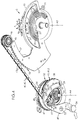
figure 1 est une vue en perspective montrant partiellement une montre équipée d'un mécanisme de répétition, - la
figure 2 est une vue en perspective du mécanisme de répétition seul, à plus grande échelle, - la
figure 3 est une vue en perspective du mécanisme de répétition, partiellement dénudé pour plus de clarté sur son architecture et son fonctionnement, - la
figure 4 est une vue en perspective du mécanisme de lafigure 3 , selon un autre angle de vue, - la
figure 5 est une vue en coupe partielle montrant le mécanisme de répétition, selon le plan de coupe V-V de lafigure 3 , - la
figure 6 est un tracé illustrant la forme du chemin de came, - la
figure 7 est une vue de détail en coupe, dans le même plan que lafigure 5 , montrant la poulie dans une position de déroulement complet de la chaîne, laquelle est schématisée sous forme d'un trait gras, - la
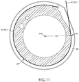
figure 8 est un diagramme montrant les variations de la distance, au centre de rotation de la poulie, du point de contact avec la chaîne, - les
figures 9 ,10 et11 sont des vues similaires à lafigure 8 , illustrant l'enroulement progressif de la chaîne sur la poulie.
- the
figure 1 is a perspective view partially showing a watch equipped with a repetition mechanism, - the
figure 2 is a perspective view of the repetition mechanism alone, on a larger scale, - the
figure 3 is a perspective view of the repetition mechanism, partially stripped for clarity on its architecture and operation, - the
figure 4 is a perspective view of the mechanism of thefigure 3 , according to another angle of view, - the
figure 5 is a partial sectional view showing the repetition mechanism, according to the sectional plane VV of thefigure 3 , - the
figure 6 is a plot illustrating the shape of the cam path, - the
figure 7 is a detail view in section, in the same plane as thefigure 5 , showing the pulley in a position of complete unfolding of the chain, which is schematized in the form of a bold line, - the
figure 8 is a diagram showing the variations of the distance, at the center of rotation of the pulley, from the point of contact with the chain, - the
figures 9 ,10 and11 are views similar to thefigure 8 , illustrating the progressive winding of the chain on the pulley.
Sur la
La montre 1 comprend un mouvement d'horlogerie conçu pour indiquer au moins les heures et les minutes. Le mouvement comprend une platine destinée à venir se loger dans le volume 3 interne défini par la carrure 2, en y étant fixé.
Le mouvement comprend par ailleurs divers composants fonctionnels regroupés par sous-ensembles. Lorsqu'un sous-ensemble a une autre fonction que d'afficher les heures, les minutes et, le cas échéant, les secondes, il est appelé « complication ».The motion further comprises various functional components grouped by subsets. When a subset has a function other than displaying the hours, the minutes and, if necessary, the seconds, it is called "complication".
Ainsi, la pièce d'horlogerie (c'est-à-dire la montre 1) illustrée est à sonnerie, et comprend, aux fins de sonner l'heure courante, un mécanisme de répétition, également appelé « complication à répétition » ou, plus simplement (et comme employé ci-après), « répétition » 5.Thus, the timepiece (that is to say the watch 1) illustrated is ringing, and includes, for the purpose of ringing the current time, a repetition mechanism, also called "repetitive complication" or, more simply (and as used hereinafter), "repetition" 5.
La répétition 5 comprend, en premier lieu, au moins un limaçon 6 des heures. Ce limaçon 6 est monté en rotation sur un axe A1. Il présente une forme générale spiralée et comprend sur sa périphérie une succession de douze secteurs angulaires de distances décroissantes à l'axe A1.
Le limaçon 6 des heures est solidaire en rotation d'une étoile 7 des heures qui comprend douze dents pointues.The snail 6 hours is integral in rotation with a
Dans l'exemple illustré sur la
La répétition 5 comprend en outre un limaçon 9 des minutes, solidaire en rotation du limaçon 8 des quarts et qui comprend quatre branches crantées sur leur pourtour, séparés par des faces de jonction lisses qui s'étendent dans le prolongement des faces de jonction du limaçon 8 des quarts.The
Le limaçon 8 des quarts porte au voisinage de sa périphérie un doigt qui, à chaque tour, vient engrener une dent de l'étoile 7 des heures pour faire tourner celle-ci d'un douzième de tour représentant une avancée d'une heure.The quarter snail 8 carries in the vicinity of its periphery a finger which, at each turn, comes to mesh a tooth of the
La répétition 5 comprend, en deuxième lieu, une pièce 10 des heures, montée en rotation autour d'un axe A3 et portant un palpeur 11 des heures.The
La pièce 10 des heures est montée en rotation autour de son axe A3 entre :
- une position de repos (en trait plein sur la
figure 5 ) dans laquelle le palpeur 11 des heures est écarté angulairement du limaçon 6 des heures, et - une position de lecture (en pointillés sur la
figure 5 ) dans laquelle le palpeur 11 des heures vient au contact du limaçon 6 des heures.
- a rest position (solid line on the
figure 5 ) in which thefeeler 11 hours is angularly spaced from the snail 6 hours, and - a reading position (dashed on the
figure 5 ) in which theprobe 11 hours comes into contact with snail 6 hours.
Comme illustré sur les
Le régulateur 13 est de préférence magnétique ; il comprend, dans ce cas, un rotor 15 monté en rotation dans un stator 16. Le rotor 15 présente une vitesse de rotation limite, déterminée par un équilibre entre la force centrifuge appliquée à des masselottes mobiles ferromagnétiques montées sur le rotor 15, et une force contre-électromotrice générée dans les masselottes par des courants de Foucault induits par un champ magnétique alterné produit par des couples d'aimants dont est pourvu le stator 16.The
La pièce 10 des heures comprend un bras 17 extérieur pourvu d'un râteau 18 des heures, constitué de douze dents en saillie. Lors du retour de la pièce 10 des heures de sa position de lecture à sa position de repos, le râteau 18 des heures actionne un marteau des heures (non représenté) qui vient frapper un timbre des heures diapasonné à une fréquence acoustique prédéterminée, éventuellement amplifiée par une pièce structurelle de la montre 1 (par ex. la carrure 2). Le marteau des heures frappe le timbre des heures un nombre de fois (compris entre un et douze) égal au nombre de dents du râteau 18 qui l'ont actionné lors du retour de la pièce 10 des heures de sa position de lecture à sa position de repos.The
La répétition 5 comprend, en quatrième lieu, un ressort 19 des heures, qui rappelle la pièce 10 des heures vers sa position de lecture. Dans l'exemple illustré, le ressort 19 des heures est un ressort spiral. Il est avantageusement fixé sur la pièce 10 des heures par une extrémité 20 interne, et sur un axe solidaire de la platine par une extrémité 21 externe.
La répétition 5 comprend, dans l'exemple illustré sur la
- une position de repos dans laquelle le palpeur 23 des quarts est écarté angulairement du limaçon 8 des quarts, et
- une position de lecture dans laquelle le palpeur 23 des quarts vient au contact du limaçon 8 des quarts.
- a rest position in which the
feeler 23 of the quarter is angularly spaced from the snail 8 quarters, and - a reading position in which the
feeler 23 quarters comes into contact with the snail 8 quarters.
La répétition comprend en outre, dans l'exemple illustré sur la
- une position de repos dans laquelle le palpeur 25 des minutes est écarté angulairement du limaçon 9 des minutes, et
- une position de lecture dans laquelle le palpeur 25 des minutes vient au contact du limaçon 9 des minutes.
- a rest position in which the minute sensor 25 is angularly spaced from the snail 9 minutes, and
- a reading position in which the minute sensor 25 comes into contact with snail 9 minutes.
La répétition comprend en outre, dans l'exemple illustré sur la
- une position de repos dans laquelle le palpeur 25 des minutes est écarté angulairement du limaçon 9 des minutes, et
- une position de lecture dans laquelle le palpeur 25 des minutes vient au contact du limaçon 9 des minutes.
- a rest position in which the feeler 25 of minutes is angularly removed from the snail 9 minutes, and
- a reading position in which the minute sensor 25 comes into contact with snail 9 minutes.
La répétition 5 comprend également un ressort 26 des quarts qui rappelle la pièce 22 des quarts vers sa position de lecture, et un ressort 27 des minutes qui rappelle la pièce 24 des minutes vers sa position de lecture.The
La pièce 24 des minutes est pourvue, sur un bras 28 extérieur, d'un râteau 29 des minutes, constitué de quatorze dents en saillie. Lors du retour de la pièce 24 des minutes de sa position de lecture à sa position de repos, le râteau 29 des minutes actionne un marteau des minutes (non représenté) qui vient frapper un timbre des minutes diapasonné à une fréquence acoustique prédéterminée différente (par ex. inférieure) à la fréquence acoustique du timbre des heures. Le marteau des minutes frappe le timbre des minutes un nombre de fois (compris entre zéro et quatorze) égal au nombre de dents du râteau 29 des minutes qui l'ont actionné lors du retour de la pièce 24 des minutes de sa position de lecture à sa position de repos.The
La pièce 22 des quarts est pourvue, sur un bras 30 extérieur, d'un râteau 31 des quarts, constitué de trois séries de dents en saillie. Lors du retour de la pièce 22 des quarts de sa position de lecture à sa position de repos, le râteau 31 des quarts actionne presque simultanément le marteau des heures et le marteau des minutes pour générer une séquence rapprochée de deux notes. Le marteau des heures et le marteau des minutes frappent leurs timbres respectifs un nombre de fois (compris entre zéro et trois) égal au nombre de séries de dents du râteau 31 des quarts qui les ont actionnés lors du retour de la pièce 22 des quarts de sa position de lecture à sa position de repos.The quarter piece 22 is provided, on an outer arm, with a
Comme on le voit sur la
La répétition 5 comprend, en cinquième lieu, un barillet 32 de sonnerie.
Le barillet 32 de sonnerie est monté en rotation autour d'un axe A4 de barillet. Le barillet 32 de sonnerie est un sous-ensemble qui comprend plusieurs composants, parmi lesquels :
- un arbre 33 de barillet,
un tambour 34 de barillet,un ressort 35 de barilletdont une extrémité 36 interne est solidaire de l'arbre 33 de barillet et une extrémité 37 externe est solidaire du tambour 34 de barillet, etune poulie 38 définit un chemin 39 de came périphérique.
- a
barrel shaft 33, - a
barrel drum 34, - a
barrel spring 35 having aninner end 36 integral with thebarrel shaft 33 and anouter end 37 integral with thebarrel drum 34, and - a
pulley 38 defines aperipheral cam path 39.
L'arbre 33 de barillet et le tambour 34 de barillet sont tous deux montés en rotation autour de l'axe A4 de barillet.The
La poulie 38 est couplée en rotation à l'arbre 33 de barillet. La poulie 38 est montée autour d'un axe de rotation qui est ici confondu avec l'axe A4 de barillet.The
La répétition 5 comprend, en sixième lieu, une chaîne 40 apte à s'enrouler partiellement sur la poulie 38, et plus précisément sur le chemin 39 de came. La chaîne 40 est accrochée, par une extrémité 41 proximale, sur la poulie 38 et, par une extrémité 42 distale, sur la pièce 10 des heures.The
La chaîne 40 comprend une pluralité de maillons 43 articulés les uns par rapport aux autres. Le maillon 43 situé à l'extrémité 41 proximale de la chaîne 40 est fixé sur une goupille 44 solidaire de la poulie 38. Le maillon 43 situé à l'extrémité 42 distale de la chaîne 40 est quant à lui fixé sur une goupille 45 solidaire du bras 17 extérieur de la pièce 10 des heures.The
Selon un mode de réalisation illustré sur les
Comme illustré sur les
Ainsi que représenté sur la
- une crémaillère 49 montée en rotation autour d'un axe A5 de crémaillère fixe, et pourvue d'un secteur 50 denté,
un rouage 51 de sonnerie en relation d'engrenage d'une part avec la crémaillère 49 et d'autre part avec l'arbre 33 de barillet.
- a
rack 49 rotatably mounted about a fixed rack axis A5, and provided with a sector 50 toothed, - a
gear wheel 51 in gear relationship on the one hand with therack 49 and on the other hand with theshaft 33 of the barrel.
La crémaillère 49 présente une forme de crochet. La crémaillère 49 est pourvue d'un alésage 52 par lequel elle est montée sur son axe A5. De part et d'autre de cet alésage 52, la crémaillère 48 comprend un levier 53 portant à son extrémité un bouton 54 (qui, dans l'exemple illustré, est rapporté et chassé dans un trou formé dans l'extrémité du levier 53), et un bras 55 coudé dans lequel est formé le secteur 50 denté.The
La crémaillère 49 est montée en rotation autour de son axe A5 entre une position de repos (
Selon un mode de réalisation illustré sur la
Dans l'exemple illustré, le rouage 51 de sonnerie comprend en outre un pignon 58 multiplicateur (partiellement arraché sur la
Comme on le voit également sur la
Comme illustré sur la
- une position désarmée dans laquelle le poussoir 60 n'exerce pas de couple moteur sur la crémaillère 49, et
- une position d'armement dans laquelle le poussoir 60 exerce sur la crémaillère 49, via
le bouton 54, une poussée (indiquée par la flèche blanche en bas à gauche sur lafigure 4 et en bas à droite sur lafigure 5 ) générant un couple moteur qui entraîne en rotation l'arbre 33 de barillet via le rouage 51 de sonnerie.
- a disarmed position in which the
pusher 60 does not exert a motor torque on therack 49, and - an arming position in which the
pusher 60 exerts on therack 49, via thebutton 54, a thrust (indicated by the white arrow in the lower left on thefigure 4 and bottom right on thefigure 5 ) generating a motor torque that rotates thebarrel shaft 33 via thewheel gear 51.
L'actionnement de la répétition 5 s'effectue par pression du doigt sur le poussoir 60. Le poussoir 60 repousse le bouton 54 qui, via le levier 53, fait pivoter la crémaillère 49 autour de son axe A5. La crémaillère 49 entraîne en rotation, par l'engrènement de son secteur 50 denté, le pignon 56 d'entrée, rotation que le pignon 58 multiplicateur, solidaire de ce dernier, transmet au pignon 57 de sortie, lequel entraîne dans sa rotation l'arbre 33 de barillet (dans le sens de la flèche F1 sur la
La chaîne 40, tractée (dans le sens de la flèche F2 sur la
Parvenue à la position de lecture, dans laquelle le palpeur 11 des heures vient au contact du limaçon 6 des heures, la pièce 10 des heures est stoppée, cependant que, le cas échéant, la pièce 22 des quarts et la pièce 24 des minutes peuvent continuer leur rotation, respectivement rappelées vers leurs positions de lecture par le ressort 26 des quarts et le ressort 27 des minutes, jusqu'à ce que le palpeur 23 des quarts et le palpeur 25 des minutes parviennent au contact, respectivement, du limaçon 8 des quarts et du limaçon 9 des minutes.Having arrived at the reading position, in which the
Le relâchement du poussoir 60 libère le ressort 35 de barillet, dont l'extrémité 37 externe demeure fixe avec le tambour 34 de barillet et dont l'extrémité 36 interne entraîne en rotation l'arbre 33 de barillet (dans le sens opposé à la flèche F1) et avec lui la poulie 38 (dans le même sens de rotation). Comme le couple de rappel imposé à la poulie par le ressort 35 de barillet est supérieur (voire très supérieur) au couple résistant opposé à la pièce 10 des heures par le ressort 19 des heures, la poulie 38 tracte (dans le sens opposé à la flèche F2) la chaîne 40 qui s'y enroule en entraînant avec elle la pièce 10 des heures en rotation autour de son axe A3 (dans le sens opposé à la flèche F3), jusqu'à ce que la pièce 10 des heures atteigne sa position de repos, à laquelle elle parvient en venant buter contre le palier 46 de renvoi, ce qui bloque la répétition 5.The release of the
Pendant la course accompagnant le relâchement du poussoir 60, la pièce 10 des heures, la pièce 22 des quarts et la pièce 24 des minutes ont, ensemble (et de la manière expliquée plus haut) sonné l'heure affichée.During the race accompanying the release of the
C'est pour que la sonnerie soit réalisée à une fréquence aussi régulière que possible que la répétition 5 est pourvue du régulateur 13.This is so that the ringing is performed at a frequency as regular as possible that the
Cependant le régulateur 13 n'est pas suffisant, car il s'avère que le couple moteur, noté C, induit sur l'arbre 33 de barillet par le ressort 35 de barillet, n'est pas constant selon la position angulaire, notée A, de la poulie 38, mesurée par référence à la position d'armement (pour laquelle, par convention, A=0). Dans ce qui suit, on appelle « Angle de poulie » cette position A angulaire.However, the
Comme on le voit sur la
La poulie 38 et la chaîne 40 définissent conjointement, sur le chemin 39 de came, un point M de contact. Ce point M de contact est situé à la limite de l'enroulement de la chaîne 38.The
Le point M de contact est le point du chemin 39 de came où la chaîne 40 débute son enroulement sur la poulie 38 ou, ce qui revient au même, le point où la chaîne 40 quitte la poulie 38. En d'autres termes, le point M de contact est situé à la jonction entre la section 40.1 droite et la section 40.2 curviligne. Selon la position angulaire de la poulie 38, le lieu du point M sur le chemin 39 de came se déplace.The point M of contact is the point of the
Le couple C moteur est transmis par l'arbre 33 de barillet à la poulie 38, qui lui est couplée en rotation autour de l'axe A4 de barillet. La poulie 38 exerce à son tour, en raison du couple C moteur généré par le ressort 35 de barillet, un effort de traction, noté T. Cet effort T de traction est appliqué au point M de contact, dans l'axe de la section 40.1 droite. On note L et on appelle « levier » la distance du point M de contact à l'axe A4 de barillet.The engine torque C is transmitted by the
Compte tenu de ces des notations, l'effort T de traction se déduit du couple C par la formule classique suivante : ![]()
![]()
Comme le couple C moteur n'est pas constant suivant l'angle A de poulie, il en résulte que, si le levier L était constant, l'effort T de traction ne serait pas constant non plus suivant l'angle A de poulie.Since the engine torque C is not constant along the pulley angle A, it follows that, if the lever L were constant, the traction force T would not be constant either according to the pulley angle A.
Tel est la fonction du chemin 39 de came : faire varier le levier L pour compenser la variation du couple C et ainsi minimiser les variations de l'effort T de traction.This is the function of the cam path 39: to vary the lever L to compensate for the variation of the torque C and thus to minimize the variations of the traction force T.
Plus précisément, il a été constaté que le couple C moteur diminue au fur et à mesure qu'augmente l'angle A de poulie, en partant de la position désarmée (illustrée sur la
C'est pourquoi le chemin 39 de came s'étend en spirale autour de l'axe A4 de barillet. Plus précisément, le levier L diminue avec l'enroulement de la chaîne 40 (c'est-à-dire au fur et à mesure qu'augmente l'angle A de poulie). En d'autres termes, la distance à l'axe A4 de barillet du point M de contact est une fonction décroissante de l'angle A de poulie.This is why the
On a tracé sur la
Le levier L varie de préférence dans une proportion comprise entre 5% et 20%. Cette variation peut sembler faible, mais elle est suffisante pour compenser les variations du couple C moteur et permettre de rendre à peu près constante la traction T exercée sur la chaîne 40 par la poulie 38 rappelée par le ressort 35 de barillet.The lever L preferably varies in a proportion of between 5% and 20%. This variation may seem small, but it is sufficient to compensate for variations in the engine torque C and make the traction T exerted on the
Dans un mode particulier de réalisation : ![]()
![]()
![]()
![]()
La variation du levier L est donc, dans cet exemple, d'environ 14% mais cet exemple ne saurait être limitatif car il dépend des performances du ressort 35.The variation of the lever L is therefore, in this example, about 14% but this example can not be limiting because it depends on the performance of the
Comme cela a déjà été suggéré, un ressort déformé tend à reprendre une configuration d'équilibre stable en générant un couple de rappel qui n'est pas constant selon sa déformation. Un examen plus précis montre qu'en général la variation du couple de rappel généré par un ressort en fonction de sa déformation n'est globalement pas linéaire mais peut l'être localement.As already suggested, a deformed spring tends to resume a stable equilibrium configuration by generating a restoring torque which is not constant according to its deformation. A more precise examination shows that, in general, the variation of the return torque generated by a spring as a function of its deformation is not generally linear but can be locally.
On comprend donc que si l'on peut maintenir le ressort 35 dans une gamme de déformation où la variation du couple généré est linéaire, il est possible de concevoir une poulie 39 dont le levier L varie également de manière linéaire en fonction de l'angle A de poulie. En d'autres termes, le chemin 39 de came est en spirale d'Archimède.It is thus understood that if it is possible to maintain the
Ainsi, dans l'exemple illustré sur la
Un exemple de construction du chemin 39 de came est illustré sur les dessins, et plus particulièrement sur la
Dans l'exemple illustré sur les
Les bénéfices de cette architecture ont déjà été évoqués ; nous les rappelons :
- minimisation des variations de la fréquence (c'est-à-dire du nombre de tintements par seconde - ou par minute) des tintements de sonnerie,
- minimisation des variations des efforts dans la chaîne. On peut noter que cela a notamment pour conséquence de limiter la fatigue mécanique dans la chaîne, et donc d'augmenter sa durée de vie.
- minimizing variations in the frequency (i.e., the number of ringings per second - or minute) of ringing tones,
- minimizing the variations of the forces in the chain. It may be noted that this has the particular consequence of limiting the mechanical fatigue in the chain, and therefore of increasing its service life.
On notera que l'architecture qui vient d'être décrite peut admettre des variantes sans sortir du cadre de l'invention.It will be noted that the architecture which has just been described may admit variants without departing from the scope of the invention.
Ainsi, il est envisageable de remplacer le barillet 32 par un autre sous-ensemble ayant la même fonction motrice. Un tel sous-ensemble comprend par exemple un ressort-poutre fonctionnant en flexion, et auquel est couplée la poulie 38 par l'intermédiaire d'une ou plusieurs pièces de liaison transformant le mouvement de flexion du ressort-poutre en mouvement de rotation de la poulie 38. La fonction d'un tel ressort-poutre est la même que celle du ressort 35 de barillet : solliciter, via la poulie 38 et la chaîne 40, la pièce 10 des heures vers sa position de repos.Thus, it is conceivable to replace the
Claims (6)
Priority Applications (4)
| Application Number | Priority Date | Filing Date | Title |
|---|---|---|---|
| EP17209993.9A EP3502794B1 (en) | 2017-12-22 | 2017-12-22 | Repetition with chain wound onto a cam |
| US16/205,293 US11175628B2 (en) | 2017-12-22 | 2018-11-30 | Repeater with a chain wound on a cam |
| JP2018227872A JP6659812B2 (en) | 2017-12-22 | 2018-12-05 | Repeater with chain wound on cam |
| CN201811571714.2A CN109960134B (en) | 2017-12-22 | 2018-12-21 | Chronograph with chain wound on cam |
Applications Claiming Priority (1)
| Application Number | Priority Date | Filing Date | Title |
|---|---|---|---|
| EP17209993.9A EP3502794B1 (en) | 2017-12-22 | 2017-12-22 | Repetition with chain wound onto a cam |
Publications (2)
| Publication Number | Publication Date |
|---|---|
| EP3502794A1 true EP3502794A1 (en) | 2019-06-26 |
| EP3502794B1 EP3502794B1 (en) | 2020-10-21 |
Family
ID=60782031
Family Applications (1)
| Application Number | Title | Priority Date | Filing Date |
|---|---|---|---|
| EP17209993.9A Active EP3502794B1 (en) | 2017-12-22 | 2017-12-22 | Repetition with chain wound onto a cam |
Country Status (4)
| Country | Link |
|---|---|
| US (1) | US11175628B2 (en) |
| EP (1) | EP3502794B1 (en) |
| JP (1) | JP6659812B2 (en) |
| CN (1) | CN109960134B (en) |
Families Citing this family (2)
| Publication number | Priority date | Publication date | Assignee | Title |
|---|---|---|---|---|
| US11241896B2 (en) | 2019-06-19 | 2022-02-08 | Seiko Epson Corporation | Housing case and tape ribbon set |
| CH716878A1 (en) * | 2019-12-02 | 2021-06-15 | Bucherer Ag | Striking mechanism, wristwatch and regulator. |
Citations (2)
| Publication number | Priority date | Publication date | Assignee | Title |
|---|---|---|---|---|
| US593274A (en) * | 1897-11-09 | Mechanism foe watches | ||
| CH707271A2 (en) * | 2012-11-27 | 2014-05-30 | Montres Breguet Sa | Watch movement unit, has winding roller arranged to slide on fixed guide transversely with wire, while being engaged in spiral groove so as to traverse groove, and wire inserted in groove when spindle turns in one direction |
Family Cites Families (16)
| Publication number | Priority date | Publication date | Assignee | Title |
|---|---|---|---|---|
| JP2008020212A (en) * | 2006-07-10 | 2008-01-31 | Seiko Epson Corp | Timepiece |
| EP2498148B1 (en) * | 2011-03-08 | 2017-11-15 | Montres Breguet SA | Safety mechanism against accidental operation of the controls of a minute-repeater |
| EP2498146B1 (en) * | 2011-03-08 | 2018-07-18 | Montres Breguet SA | Grande sonnerie wake-up alarm mechanism |
| EP2498143B1 (en) * | 2011-03-08 | 2018-05-02 | Montres Breguet SA | Isolation mechanism between timepiece mechanisms for setting off different acoustic signals |
| CH706209B1 (en) * | 2012-03-07 | 2016-06-30 | Montres Romain Gauthier Sa | watch movement including a constant torque barrel. |
| EP2735919B1 (en) * | 2012-11-27 | 2015-07-22 | Montres Breguet SA | Watch movement comprising a fusee |
| CH707273B1 (en) * | 2012-11-28 | 2017-03-15 | Red & White Intellectual Property Man Sa | Ring mechanism. |
| CH710189A1 (en) * | 2014-09-23 | 2016-03-31 | Complitime Sa | striking mechanism. |
| DE102014119622B3 (en) * | 2014-12-23 | 2015-08-13 | Lange Uhren Gmbh | Clock |
| EP3070542A1 (en) * | 2015-03-18 | 2016-09-21 | Glashütter Uhrenbetrieb GmbH | Repetition striking mechanism with dedicated winding and trigger gear trains |
| CH711112A2 (en) * | 2015-05-21 | 2016-11-30 | Blancpain Sa | Selection security mechanism and / or clock ringing trigger. |
| DE102015006680A1 (en) * | 2015-05-22 | 2016-12-08 | Walter Rehm | Clock with acoustic seconds display |
| EP3217227B1 (en) * | 2016-03-11 | 2019-02-27 | The Swatch Group Research and Development Ltd. | Timepiece regulator mechanism with optimised magnetic escapement |
| EP3339976A1 (en) * | 2016-12-23 | 2018-06-27 | Blancpain SA | Mechanical watch with repeater |
| EP3502795B1 (en) * | 2017-12-22 | 2020-09-23 | Montres Breguet S.A. | Repetition mechanism with tensioned chain |
| EP3508925B1 (en) * | 2018-01-04 | 2021-12-08 | Montres Breguet S.A. | Repetition with disengageable transmission mobile |
-
2017
- 2017-12-22 EP EP17209993.9A patent/EP3502794B1/en active Active
-
2018
- 2018-11-30 US US16/205,293 patent/US11175628B2/en active Active
- 2018-12-05 JP JP2018227872A patent/JP6659812B2/en active Active
- 2018-12-21 CN CN201811571714.2A patent/CN109960134B/en active Active
Patent Citations (2)
| Publication number | Priority date | Publication date | Assignee | Title |
|---|---|---|---|---|
| US593274A (en) * | 1897-11-09 | Mechanism foe watches | ||
| CH707271A2 (en) * | 2012-11-27 | 2014-05-30 | Montres Breguet Sa | Watch movement unit, has winding roller arranged to slide on fixed guide transversely with wire, while being engaged in spiral groove so as to traverse groove, and wire inserted in groove when spindle turns in one direction |
Non-Patent Citations (1)
| Title |
|---|
| "Les Montres Compliquées", 2013 |
Also Published As
| Publication number | Publication date |
|---|---|
| US11175628B2 (en) | 2021-11-16 |
| EP3502794B1 (en) | 2020-10-21 |
| CN109960134B (en) | 2021-04-06 |
| US20190196410A1 (en) | 2019-06-27 |
| JP2019113539A (en) | 2019-07-11 |
| CN109960134A (en) | 2019-07-02 |
| JP6659812B2 (en) | 2020-03-04 |
Similar Documents
| Publication | Publication Date | Title |
|---|---|---|
| EP1658531B1 (en) | Display device for timepiece | |
| EP1970778B1 (en) | Timepiece comprising a device indicating the power reserve | |
| EP2407833B1 (en) | Clearance compensation mechanism for clock movement | |
| EP3502795B1 (en) | Repetition mechanism with tensioned chain | |
| EP1933210A1 (en) | Time setting element for an hour indicator | |
| EP3502794B1 (en) | Repetition with chain wound onto a cam | |
| CH712219A2 (en) | Mechanism for watch movement with retrograde and jumping display. | |
| EP3508925B1 (en) | Repetition with disengageable transmission mobile | |
| CH712222B1 (en) | Date indicator drive wheel, calendar mechanism, movement and timepiece. | |
| FR2097126A1 (en) | ||
| CH714504A2 (en) | Rewind mechanism with a chain wound on a cam for a timepiece with a bell. | |
| CH706808B1 (en) | Minute repeater watch. | |
| EP2577405A1 (en) | Indicator of the power reserve of a timepiece | |
| EP0816954B1 (en) | Timepiece with a hand-setting mechanism actuated by direct action of the pull-out piece | |
| CH714506A2 (en) | Tensioned string rehearsal mechanism for a timepiece with bell. | |
| CH707181A2 (en) | Clockwork device for use in clockwork movement of e.g. wristwatch, has control unit kinematically connected to jumping wheel and arranged to start action in minute jumping display mechanism at instants corresponding to jumps | |
| EP1102134A1 (en) | Retrograde sector display device | |
| CH707136A1 (en) | Timepiece for indicating the power reserve. | |
| CH707439B1 (en) | Anti-retrograde display mechanism for a timepiece. | |
| CH714537A2 (en) | Repetition to mobile disengageable transmission. | |
| EP3486735A1 (en) | Second reset clock mechanism with snail cam | |
| EP4092491A1 (en) | Timepiece movement with clutch | |
| CH717172B1 (en) | Timepiece intended to display the current time or a chronograph function with the same hands. | |
| CH170141A (en) | Time indicating device for a timepiece. | |
| EP1353244A1 (en) | Timepiece with oblong shaped case |
Legal Events
| Date | Code | Title | Description |
|---|---|---|---|
| PUAI | Public reference made under article 153(3) epc to a published international application that has entered the european phase |
Free format text: ORIGINAL CODE: 0009012 |
|
| STAA | Information on the status of an ep patent application or granted ep patent |
Free format text: STATUS: THE APPLICATION HAS BEEN PUBLISHED |
|
| AK | Designated contracting states |
Kind code of ref document: A1 Designated state(s): AL AT BE BG CH CY CZ DE DK EE ES FI FR GB GR HR HU IE IS IT LI LT LU LV MC MK MT NL NO PL PT RO RS SE SI SK SM TR |
|
| AX | Request for extension of the european patent |
Extension state: BA ME |
|
| STAA | Information on the status of an ep patent application or granted ep patent |
Free format text: STATUS: REQUEST FOR EXAMINATION WAS MADE |
|
| 17P | Request for examination filed |
Effective date: 20200102 |
|
| RBV | Designated contracting states (corrected) |
Designated state(s): AL AT BE BG CH CY CZ DE DK EE ES FI FR GB GR HR HU IE IS IT LI LT LU LV MC MK MT NL NO PL PT RO RS SE SI SK SM TR |
|
| GRAP | Despatch of communication of intention to grant a patent |
Free format text: ORIGINAL CODE: EPIDOSNIGR1 |
|
| STAA | Information on the status of an ep patent application or granted ep patent |
Free format text: STATUS: GRANT OF PATENT IS INTENDED |
|
| INTG | Intention to grant announced |
Effective date: 20200608 |
|
| GRAS | Grant fee paid |
Free format text: ORIGINAL CODE: EPIDOSNIGR3 |
|
| GRAA | (expected) grant |
Free format text: ORIGINAL CODE: 0009210 |
|
| STAA | Information on the status of an ep patent application or granted ep patent |
Free format text: STATUS: THE PATENT HAS BEEN GRANTED |
|
| AK | Designated contracting states |
Kind code of ref document: B1 Designated state(s): AL AT BE BG CH CY CZ DE DK EE ES FI FR GB GR HR HU IE IS IT LI LT LU LV MC MK MT NL NO PL PT RO RS SE SI SK SM TR |
|
| REG | Reference to a national code |
Ref country code: GB Ref legal event code: FG4D Free format text: NOT ENGLISH |
|
| REG | Reference to a national code |
Ref country code: CH Ref legal event code: EP |
|
| REG | Reference to a national code |
Ref country code: IE Ref legal event code: FG4D Free format text: LANGUAGE OF EP DOCUMENT: FRENCH |
|
| REG | Reference to a national code |
Ref country code: DE Ref legal event code: R096 Ref document number: 602017025783 Country of ref document: DE |
|
| REG | Reference to a national code |
Ref country code: CH Ref legal event code: NV Representative=s name: ICB INGENIEURS CONSEILS EN BREVETS SA, CH |
|
| REG | Reference to a national code |
Ref country code: AT Ref legal event code: REF Ref document number: 1326437 Country of ref document: AT Kind code of ref document: T Effective date: 20201115 |
|
| REG | Reference to a national code |
Ref country code: AT Ref legal event code: MK05 Ref document number: 1326437 Country of ref document: AT Kind code of ref document: T Effective date: 20201021 |
|
| REG | Reference to a national code |
Ref country code: NL Ref legal event code: MP Effective date: 20201021 |
|
| PG25 | Lapsed in a contracting state [announced via postgrant information from national office to epo] |
Ref country code: NO Free format text: LAPSE BECAUSE OF FAILURE TO SUBMIT A TRANSLATION OF THE DESCRIPTION OR TO PAY THE FEE WITHIN THE PRESCRIBED TIME-LIMIT Effective date: 20210121 Ref country code: PT Free format text: LAPSE BECAUSE OF FAILURE TO SUBMIT A TRANSLATION OF THE DESCRIPTION OR TO PAY THE FEE WITHIN THE PRESCRIBED TIME-LIMIT Effective date: 20210222 Ref country code: RS Free format text: LAPSE BECAUSE OF FAILURE TO SUBMIT A TRANSLATION OF THE DESCRIPTION OR TO PAY THE FEE WITHIN THE PRESCRIBED TIME-LIMIT Effective date: 20201021 Ref country code: FI Free format text: LAPSE BECAUSE OF FAILURE TO SUBMIT A TRANSLATION OF THE DESCRIPTION OR TO PAY THE FEE WITHIN THE PRESCRIBED TIME-LIMIT Effective date: 20201021 Ref country code: GR Free format text: LAPSE BECAUSE OF FAILURE TO SUBMIT A TRANSLATION OF THE DESCRIPTION OR TO PAY THE FEE WITHIN THE PRESCRIBED TIME-LIMIT Effective date: 20210122 |
|
| REG | Reference to a national code |
Ref country code: LT Ref legal event code: MG4D |
|
| PG25 | Lapsed in a contracting state [announced via postgrant information from national office to epo] |
Ref country code: SE Free format text: LAPSE BECAUSE OF FAILURE TO SUBMIT A TRANSLATION OF THE DESCRIPTION OR TO PAY THE FEE WITHIN THE PRESCRIBED TIME-LIMIT Effective date: 20201021 Ref country code: ES Free format text: LAPSE BECAUSE OF FAILURE TO SUBMIT A TRANSLATION OF THE DESCRIPTION OR TO PAY THE FEE WITHIN THE PRESCRIBED TIME-LIMIT Effective date: 20201021 Ref country code: AT Free format text: LAPSE BECAUSE OF FAILURE TO SUBMIT A TRANSLATION OF THE DESCRIPTION OR TO PAY THE FEE WITHIN THE PRESCRIBED TIME-LIMIT Effective date: 20201021 Ref country code: PL Free format text: LAPSE BECAUSE OF FAILURE TO SUBMIT A TRANSLATION OF THE DESCRIPTION OR TO PAY THE FEE WITHIN THE PRESCRIBED TIME-LIMIT Effective date: 20201021 Ref country code: IS Free format text: LAPSE BECAUSE OF FAILURE TO SUBMIT A TRANSLATION OF THE DESCRIPTION OR TO PAY THE FEE WITHIN THE PRESCRIBED TIME-LIMIT Effective date: 20210221 Ref country code: LV Free format text: LAPSE BECAUSE OF FAILURE TO SUBMIT A TRANSLATION OF THE DESCRIPTION OR TO PAY THE FEE WITHIN THE PRESCRIBED TIME-LIMIT Effective date: 20201021 Ref country code: BG Free format text: LAPSE BECAUSE OF FAILURE TO SUBMIT A TRANSLATION OF THE DESCRIPTION OR TO PAY THE FEE WITHIN THE PRESCRIBED TIME-LIMIT Effective date: 20210121 |
|
| PG25 | Lapsed in a contracting state [announced via postgrant information from national office to epo] |
Ref country code: NL Free format text: LAPSE BECAUSE OF FAILURE TO SUBMIT A TRANSLATION OF THE DESCRIPTION OR TO PAY THE FEE WITHIN THE PRESCRIBED TIME-LIMIT Effective date: 20201021 Ref country code: HR Free format text: LAPSE BECAUSE OF FAILURE TO SUBMIT A TRANSLATION OF THE DESCRIPTION OR TO PAY THE FEE WITHIN THE PRESCRIBED TIME-LIMIT Effective date: 20201021 |
|
| REG | Reference to a national code |
Ref country code: DE Ref legal event code: R097 Ref document number: 602017025783 Country of ref document: DE |
|
| PG25 | Lapsed in a contracting state [announced via postgrant information from national office to epo] |
Ref country code: SK Free format text: LAPSE BECAUSE OF FAILURE TO SUBMIT A TRANSLATION OF THE DESCRIPTION OR TO PAY THE FEE WITHIN THE PRESCRIBED TIME-LIMIT Effective date: 20201021 Ref country code: RO Free format text: LAPSE BECAUSE OF FAILURE TO SUBMIT A TRANSLATION OF THE DESCRIPTION OR TO PAY THE FEE WITHIN THE PRESCRIBED TIME-LIMIT Effective date: 20201021 Ref country code: SM Free format text: LAPSE BECAUSE OF FAILURE TO SUBMIT A TRANSLATION OF THE DESCRIPTION OR TO PAY THE FEE WITHIN THE PRESCRIBED TIME-LIMIT Effective date: 20201021 Ref country code: EE Free format text: LAPSE BECAUSE OF FAILURE TO SUBMIT A TRANSLATION OF THE DESCRIPTION OR TO PAY THE FEE WITHIN THE PRESCRIBED TIME-LIMIT Effective date: 20201021 Ref country code: CZ Free format text: LAPSE BECAUSE OF FAILURE TO SUBMIT A TRANSLATION OF THE DESCRIPTION OR TO PAY THE FEE WITHIN THE PRESCRIBED TIME-LIMIT Effective date: 20201021 Ref country code: LT Free format text: LAPSE BECAUSE OF FAILURE TO SUBMIT A TRANSLATION OF THE DESCRIPTION OR TO PAY THE FEE WITHIN THE PRESCRIBED TIME-LIMIT Effective date: 20201021 |
|
| PLBE | No opposition filed within time limit |
Free format text: ORIGINAL CODE: 0009261 |
|
| STAA | Information on the status of an ep patent application or granted ep patent |
Free format text: STATUS: NO OPPOSITION FILED WITHIN TIME LIMIT |
|
| PG25 | Lapsed in a contracting state [announced via postgrant information from national office to epo] |
Ref country code: DK Free format text: LAPSE BECAUSE OF FAILURE TO SUBMIT A TRANSLATION OF THE DESCRIPTION OR TO PAY THE FEE WITHIN THE PRESCRIBED TIME-LIMIT Effective date: 20201021 Ref country code: MC Free format text: LAPSE BECAUSE OF FAILURE TO SUBMIT A TRANSLATION OF THE DESCRIPTION OR TO PAY THE FEE WITHIN THE PRESCRIBED TIME-LIMIT Effective date: 20201021 |
|
| REG | Reference to a national code |
Ref country code: BE Ref legal event code: MM Effective date: 20201231 |
|
| 26N | No opposition filed |
Effective date: 20210722 |
|
| PG25 | Lapsed in a contracting state [announced via postgrant information from national office to epo] |
Ref country code: LU Free format text: LAPSE BECAUSE OF NON-PAYMENT OF DUE FEES Effective date: 20201222 Ref country code: IT Free format text: LAPSE BECAUSE OF FAILURE TO SUBMIT A TRANSLATION OF THE DESCRIPTION OR TO PAY THE FEE WITHIN THE PRESCRIBED TIME-LIMIT Effective date: 20201021 Ref country code: AL Free format text: LAPSE BECAUSE OF FAILURE TO SUBMIT A TRANSLATION OF THE DESCRIPTION OR TO PAY THE FEE WITHIN THE PRESCRIBED TIME-LIMIT Effective date: 20201021 Ref country code: IE Free format text: LAPSE BECAUSE OF NON-PAYMENT OF DUE FEES Effective date: 20201222 |
|
| PG25 | Lapsed in a contracting state [announced via postgrant information from national office to epo] |
Ref country code: SI Free format text: LAPSE BECAUSE OF FAILURE TO SUBMIT A TRANSLATION OF THE DESCRIPTION OR TO PAY THE FEE WITHIN THE PRESCRIBED TIME-LIMIT Effective date: 20201021 |
|
| PG25 | Lapsed in a contracting state [announced via postgrant information from national office to epo] |
Ref country code: IS Free format text: LAPSE BECAUSE OF FAILURE TO SUBMIT A TRANSLATION OF THE DESCRIPTION OR TO PAY THE FEE WITHIN THE PRESCRIBED TIME-LIMIT Effective date: 20210221 Ref country code: TR Free format text: LAPSE BECAUSE OF FAILURE TO SUBMIT A TRANSLATION OF THE DESCRIPTION OR TO PAY THE FEE WITHIN THE PRESCRIBED TIME-LIMIT Effective date: 20201021 Ref country code: MT Free format text: LAPSE BECAUSE OF FAILURE TO SUBMIT A TRANSLATION OF THE DESCRIPTION OR TO PAY THE FEE WITHIN THE PRESCRIBED TIME-LIMIT Effective date: 20201021 Ref country code: CY Free format text: LAPSE BECAUSE OF FAILURE TO SUBMIT A TRANSLATION OF THE DESCRIPTION OR TO PAY THE FEE WITHIN THE PRESCRIBED TIME-LIMIT Effective date: 20201021 |
|
| PG25 | Lapsed in a contracting state [announced via postgrant information from national office to epo] |
Ref country code: MK Free format text: LAPSE BECAUSE OF FAILURE TO SUBMIT A TRANSLATION OF THE DESCRIPTION OR TO PAY THE FEE WITHIN THE PRESCRIBED TIME-LIMIT Effective date: 20201021 |
|
| PG25 | Lapsed in a contracting state [announced via postgrant information from national office to epo] |
Ref country code: BE Free format text: LAPSE BECAUSE OF NON-PAYMENT OF DUE FEES Effective date: 20201231 |
|
| P01 | Opt-out of the competence of the unified patent court (upc) registered |
Effective date: 20230611 |
|
| PGFP | Annual fee paid to national office [announced via postgrant information from national office to epo] |
Ref country code: GB Payment date: 20231121 Year of fee payment: 7 |
|
| PGFP | Annual fee paid to national office [announced via postgrant information from national office to epo] |
Ref country code: FR Payment date: 20231122 Year of fee payment: 7 Ref country code: DE Payment date: 20231121 Year of fee payment: 7 |
|
| PGFP | Annual fee paid to national office [announced via postgrant information from national office to epo] |
Ref country code: CH Payment date: 20240101 Year of fee payment: 7 |