EP3501904A1 - Load carrier foot - Google Patents
Load carrier foot Download PDFInfo
- Publication number
- EP3501904A1 EP3501904A1 EP17208333.9A EP17208333A EP3501904A1 EP 3501904 A1 EP3501904 A1 EP 3501904A1 EP 17208333 A EP17208333 A EP 17208333A EP 3501904 A1 EP3501904 A1 EP 3501904A1
- Authority
- EP
- European Patent Office
- Prior art keywords
- load carrier
- carrier foot
- load
- locking
- load bar
- Prior art date
- Legal status (The legal status is an assumption and is not a legal conclusion. Google has not performed a legal analysis and makes no representation as to the accuracy of the status listed.)
- Granted
Links
- 230000007246 mechanism Effects 0.000 claims abstract description 53
- 230000008878 coupling Effects 0.000 claims description 12
- 238000010168 coupling process Methods 0.000 claims description 12
- 238000005859 coupling reaction Methods 0.000 claims description 12
- 210000003813 thumb Anatomy 0.000 claims description 4
- 230000009471 action Effects 0.000 description 4
- 239000000969 carrier Substances 0.000 description 4
- 230000004048 modification Effects 0.000 description 2
- 238000012986 modification Methods 0.000 description 2
- 238000005452 bending Methods 0.000 description 1
- 230000008901 benefit Effects 0.000 description 1
- 230000015572 biosynthetic process Effects 0.000 description 1
- 238000010276 construction Methods 0.000 description 1
- 230000001419 dependent effect Effects 0.000 description 1
- 238000005755 formation reaction Methods 0.000 description 1
- 239000002184 metal Substances 0.000 description 1
Images


Classifications
-
- B—PERFORMING OPERATIONS; TRANSPORTING
- B60—VEHICLES IN GENERAL
- B60R—VEHICLES, VEHICLE FITTINGS, OR VEHICLE PARTS, NOT OTHERWISE PROVIDED FOR
- B60R9/00—Supplementary fittings on vehicle exterior for carrying loads, e.g. luggage, sports gear or the like
- B60R9/04—Carriers associated with vehicle roof
- B60R9/058—Carriers associated with vehicle roof characterised by releasable attaching means between carrier and roof
-
- B—PERFORMING OPERATIONS; TRANSPORTING
- B60—VEHICLES IN GENERAL
- B60R—VEHICLES, VEHICLE FITTINGS, OR VEHICLE PARTS, NOT OTHERWISE PROVIDED FOR
- B60R11/00—Arrangements for holding or mounting articles, not otherwise provided for
- B60R2011/0001—Arrangements for holding or mounting articles, not otherwise provided for characterised by position
- B60R2011/004—Arrangements for holding or mounting articles, not otherwise provided for characterised by position outside the vehicle
-
- B—PERFORMING OPERATIONS; TRANSPORTING
- B60—VEHICLES IN GENERAL
- B60R—VEHICLES, VEHICLE FITTINGS, OR VEHICLE PARTS, NOT OTHERWISE PROVIDED FOR
- B60R11/00—Arrangements for holding or mounting articles, not otherwise provided for
- B60R2011/0042—Arrangements for holding or mounting articles, not otherwise provided for characterised by mounting means
- B60R2011/0049—Arrangements for holding or mounting articles, not otherwise provided for characterised by mounting means for non integrated articles
- B60R2011/005—Connection with the vehicle part
- B60R2011/0052—Connection with the vehicle part using screws, bolts, rivets or the like
Landscapes
- Engineering & Computer Science (AREA)
- Mechanical Engineering (AREA)
- Fittings On The Vehicle Exterior For Carrying Loads, And Devices For Holding Or Mounting Articles (AREA)
Abstract
Description
- The invention relates to a load carrier foot for supporting a load bar on a vehicle.
- Load carriers for vehicles which are mounted on the roofs of the vehicles are widely known in the art. Such load carriers typically comprise a load bar as well as load carrier feet which are coupled to the load bar and adapted to support the load bar on the vehicle roof. For mounting such load carriers, vehicles can comprise roof railings on which the load carrier feet can be fixed or the load carrier feet can be specifically designed to be mounted on roofs without roof railings.
- In known load carriers, load bars typically comprise recesses on their lower sides extending in the longitudinal direction of the load bars and configured to accommodate a mounting section of the load carrier foot therein. These recesses have a certain length and allow a positioning of the load carrier foot with respect to the load bar in the longitudinal direction of the load bar. In other words, the distance between two load carrier feet can be adapted by sliding them in the recesses with respect to each other.
- The ability of the load carrier feet to slide in the recesses is not always wanted and is in particular not wanted when the load carrier is fixedly clamped on the vehicle. In order to prevent a load carrier foot from sliding in the recess, clamping mechanisms are known which securely clamp the load carrier foot to the load bar when the clamping mechanism is operated. For example, it is known to provide a lever operated clamping mechanism which, when the lever is operated, locks the load carrier foot to the load bar. While such systems allow to properly lock the load carrier foot on the load bar, the operation of such systems is often not very user friendly.
- In view of the above background, it is the object to provide a load carrier foot which addresses the foregoing problems. In particular, it is an object to provide a load carrier foot with enhanced user friendliness.
- The object is solved by a load carrier foot according to independent claim 1 and/or according to the following summary. Advantageous further formations are subject of the dependent claims wherein specific further modifications can be gleaned from the following summary.
- According to an aspect, a load carrier foot for supporting a load bar on a vehicle is provided. The load carrier foot comprises a locking mechanism for releasably locking the load bar on the load carrier foot. Furthermore, the locking mechanism is configured to automatically return into a locking state in which the load bar is locked on the load carrier foot.
- The above configuration of the load carrier foot has the advantage that when the load carrier foot is mounted on the load bar, it remains locked with the load bar unless the locking is released by operation of a user. In this way, an undesired movement of the load carrier foot with respect to the load bar is prevented without the need of any further user action.
- In the context of the present subject matter, configured to automatically return into a locking state means that the locking mechanism has the capability to return into the locking state on its own and without user action. On the other hand, a user action is necessary for releasing the locking state. Such a user action can be the operation of a lever, button or other operating means which allows to induce an operating force into the locking mechanism for releasing the locking state.
- Preferably, the locking mechanism comprises a locking member configured to engage with the load bar and a biasing member for continuously applying an engaging force on the locking member.
- By using a locking member and a biasing member for applying an engaging force on the locking member, the above-mentioned capability of the load carrier foot is achieved with a simple and cost efficient construction.
- Generally, the locking member can be any means which is configured to engage with the load bar. Preferably, the locking member is configured to engage with the load bar by friction fit or positive locking. In the context of the present subject matter, friction fit relates to a condition in which the locking between locking member and load bar is achieved due to friction between the locking member and the load bar. Positive locking, also referred to as form fit, relates to a condition in which the locking between locking member and load bar is achieved by an engagement in which the locking member is brought into a position where it forms an abutment for the load bar and thus prevents a movement of the load bar.
- The biasing member can be a spring. However, it is generally possible to use other means which are configured to continuously apply a force on the locking member. Such a means does not necessarily have to be a single element but can also be a mechanism consisting of an elastic element and a force transfer element or a mechanism coupled to the locking member. Such a force transfer element can be a bar or a wire, for instance.
- Preferably, the locking member is supported rotatable about a rotational axis. Accordingly, the locking member can be rotated about the rotational axis in order to lock and unlock the load carrier foot on the load bar. The rotational axis can be arranged substantially perpendicular to a longitudinal extension direction of the load bar. For example, the locking member can be supported in a seesaw-like manner, that is by a single pivot point. For that, the locking member can comprise a pivot pin or an opening for accommodating a pivot pin. The pivot pin can be integrally formed with the locking member or can be coupled to the locking member so as to integrally rotate therewith. On the other hand, the pivot pin can be non-rotatably fixed and the locking member can be configured to rotate relative to the pivot pin. Instead of a pivot pin, any suitable support allowing the latter movement of the locking member can be used. For example, a cylindrically shaped supporting surface can be provided on which at least a portion of the locking member slides about the rotational axis.
- The rotational axis can be arranged along the width of the load bar which in the context of the present subject matter means that the rotational axis can extend in the longitudinal direction of a vehicle when the load carrier comprising the load carrier foot and the load bar as described before is mounted on the vehicle. The width direction can also be defined as a direction which is substantially perpendicular to the longitudinal extension direction of the load bar and substantially parallel to a loading plane which is defined by two load bars mounted on the roof of the vehicle at a predefined distance from each other.
- Preferably, the load carrier foot further comprises an operating member for transferring the locking mechanism into a release state in which the load bar is unlocked from the load carrier foot. In the context of the present subject matter, unlocked from the load carrier foot means that the load bar is a least movable with respect to the load carrier foot. Thus, the locking member can be operatively coupled with the locking member in order to move the same. The operating member can be directly coupled with the locking member and can even be integrally formed with the locking member. In other words, the locking member can be a portion of the operating member. On the other hand, the operating member can also be directly coupled with the locking member by a suitable force transmitting member or mechanism.
- Preferably, the operating member is configured to transfer a release force applied on the operating member by a user onto the locking member in a direction opposite to the engaging direction. In other words, the operation of the operating member leads to a generation of a counterforce acting against the engaging force.
- Preferably, the locking member comprises an engaging section adapted to contact the load bar and force transmittingly coupled to a first portion of the operating member. The locking member can comprise a supporting section which is adapted to rotatably support the locking member on a support member of the load carrier foot. The locking member can comprise a coupling section which is force transmittingly coupled to a second portion of the operating member.
- The locking member, in particular the engaging section, the supporting section and a coupling section can be integrally formed. For example, the locking member can be formed by bending a sheet metal.
- The engaging section can be specifically designed to allow a proper engagement with a corresponding section in the load bar. For example, the engaging section can comprise teeth for contacting a surface on the load bar or for engaging with corresponding recesses formed in the load bar.
- Furthermore, the engaging section can comprise an opening for fixing a force transfer member, e.g. pulling member thereto. The pulling member can be a pull rod. In case an opening is provided in the supporting section, the teeth can be arranged on opposite sides of the opening, i.e. in width direction of the load carrier foot and in width direction of the load bar. Furthermore, the tips of the teeth can be oriented such that they face in a direction which is substantially parallel to a middle axis of the opening. The engaging section can be force transmittingly coupled to a first portion of the operating member. For example, the engaging section can be force transmittingly coupled to the first portion of the operating member by means of the force transfer member as mentioned before. In this way, it is possible to apply a force, e.g. a pulling force, on the engaging section by way of a movement of the operating member.
- In order to rotatably support the locking member on the support member of the load carrier foot, the supporting section can be formed in the shape of a circular arc. In other words, the supporting section can comprise a curved portion or an arc portion or section which can be brought in contact with the support member of the load carrier foot. The arc portion comprises an inner wall which extends about the curvature centre or curvature centre axis of the arc portion. The inner wall, which can also be referred to as sliding wall, can be slidingly supported on a correspondingly curved supporting section on the support member of the load carrier foot. In this way, a hinged coupling between the support member and the locking member can be achieved. However, it is also possible to hingedly couple the locking member on the support member in a different manner. For example, the locking member can be coupled to the support member by means of a pivot pin about which the locking member can be rotated. The support member can be a rear cover of the load carrier foot, i.e. a cover which is arranged on the vehicle side or which is facing towards the vehicle center when the load carrier foot is mounted on the vehicle. The load carrier foot can comprise a foot pad for contacting the vehicle roof and for transferring a load onto the vehicle roof. The support member, e.g. the rear cover, can be movably, e.g. rotatably, supported on the foot pad. More precisely, a lower portion of the support member can be specifically designed to be supported on an upper side of the foot pad. Furthermore, the support member can be configured to support a load bar thereon. In other words, the upper portion of the support member can be configured to support a load bar thereon. Thus, the support member is able to transfer a load received from a load bar onto the foot pad. In this way, a major part of a normal force applied on the load carrier foot by the load bar is directly transferred to the foot pad by means of the support member. The configuration can be such that the foot pad only receives forces from the support member, e.g. the rear cover.
- As mentioned before, the locking member can comprise a coupling section which can be force transmittingly coupled to a second portion of the operating member. For example, the coupling section can be directly force transmittingly coupled to the second portion of the operating member. For that, the coupling section can comprise a recess which is hookable with a hook provided in the operating member. An inverse arrangement of hook and recess is also possible. By way of such a configuration, it is preferably possible to apply a pulling force on the coupling section by way of a movement of the operating member in a second direction.
- Preferably, the engaging section is adapted to be arranged inside the load bar and to engage with or apply pressure on an interior surface of the load bar. For that, the locking member can be arranged on the load carrier foot such that it can extend through a recess formed in the load bar, when the load bar is mounted on the load carrier foot. The engaging section can be formed as described before and can be an integral part of the above described locking member. The engaging section is arranged such that a distance between the same and the support member can be varied. The locking member is formed and arranged such that the engaging section remains inside the load bar independent from the position or orientation of the locking member on the support member.
- Preferably, the locking mechanism comprises a force transfer member, preferably a threaded bolt or screw, coupled to the engaging section at one end and to the first portion of the operating member at a second end. The force transfer member can be the above described pulling member. On the other hand, any member which is able to at least transfer a sufficiently high pulling force can be suitably used as force transfer member. As an example, the force transfer member can be a threaded rod coupled to the engaging section by means of a nut and having a head portion which is supported on an inner surface of the operating member.
- Preferably, the biasing member is a coil spring wound around the force transfer member. For example, the coil spring can be arranged such that one end is supported on an inner surface of the support member, e.g. the rear cover of a load carrier foot, on which the load bar is supported and one end can be supported against a supporting member or operating member. In this way, the supporting member and the force transfer member are biased in such a manner that the engaging section is pulled towards the support member, e.g. the rear cover, and thus brought in contact with an inner lower wall of the load bar and pushes the same against the support member. In other words, the engaging section is spring-biased towards a clamping state and, therefore, automatically returns into that state.
- Preferably, the support member comprises a supporting portion adapted to contact an outer surface of the load bar. The supporting portion and the engaging section can form a clamping section for fixedly holding a wall portion of the load bar between them. The supporting portion can comprise a supporting surface facing the engaging section. In other words, a wall portion of the load bar can be accommodated between the supporting surface and the engaging section. The engaging section is pretensioned so as to be pulled towards the supporting surface in order to press the wall portion of the load bar onto the supporting surface.
- Preferably, the support member comprises a pivot portion, preferably having a substantially cylindrical shape and adapted to support the supporting section pivotably about the rotational axis, wherein the pivot portion and the supporting portion are preferably integrally formed.
- Preferably, the locking mechanism is further configured to take a securing state in which the engaging force on the locking member is increased. Thus, the securing state can be a state in which an additional force is applied on the locking member so that the clamping force is increased.
- Preferably, the load carrier foot further comprises a clamping mechanism for clamping the load carrier foot to the vehicle. The clamping mechanism can be operatively coupled to the locking mechanism such that the engaging force on the locking member is increased upon tightening the clamping mechanism. Accordingly, a securing state in which the engaging force on the locking member is increased can be achieved by an operation of the clamping mechanism. Consequently, when the load carrier foot is securely clamped on a vehicle, the locking mechanism is in the securing state and remains in this state until the clamping mechanism is released.
- Preferably, the locking mechanism is further configured to take a securing state in which a movement of the locking member is blocked. Alternatively or in addition, the locking mechanism is configured to take a securing state in which a movement of the operating member is blocked. Accordingly, it is possible to provide a securing state by locking a movement of the locking member or of the operating member in a direction in which the engaging section is disengaged from the load bar.
- Preferably, the operating member comprises an operating portion, preferably two operating portions. The operating portion preferably comprises at least one push surface configured for thumb operation. According to an example, the operating portion comprises two push surfaces. The operating portions can be integrally formed such that they are accessible for a user and not obstructed by further elements of the load carrier foot other than a covering. For example, the load carrier foot can comprise a load carrier bracket for fixing the load carrier foot to the roof of a vehicle. In addition, the load carrier foot can comprise a holder for holding such a load carrier bracket. The operating member can thus be configured so that neither the load carrier bracket nor the holder obstruct access to the operating portion. For example, the operating member can be formed such that at least one operating portion, preferably both operating portions protrude laterally so that a user is able to operate them by laterally passing a thumb by the holder or bracket and pushing against the operating portion. The direction in which the operating portion protrudes laterally can be the width direction of the load carrier foot, i.e. a width direction of a load bar supported thereon, or a longitudinal direction of the vehicle when the load carrier foot is mounted on the vehicle.
-
-
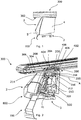
Fig. 1 shows side view of an assembly comprising a load carrier foot according to an embodiment. -
Fig.2 shows a perspective sectional view of the assembly ofFig. 1 . -
Fig. 3 shows a perspective enlarged view of an upper portion of the load carrier foot ofFig. 1 . -
Fig. 4 shows a perspective view of components of a locking mechanism of the load carrier foot. -
Fig. 5 shows a sectional view of the assembly ofFig. 1 . -
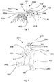
Fig. 6 shows a perspective view of components of the assembly ofFig. 1 - In the following, an embodiment as well as modifications of the present subject matter will be described with reference to the drawings. It is to be noted that similar elements in the drawings are denoted with the same reference signs.
-
Fig. 1 shows a side view of an assembly comprising aload carrier foot 2 according to an embodiment. Aload bar 300 is supported on an upper portion of theload carrier foot 2. More precisely, anouter surface 302 of theload bar 300 is supported on the upper portion of theload carrier foot 2. Furthermore, aload carrier bracket 700 is inserted into and fixedly held in theload carrier foot 2. Theload carrier foot 2 further comprises afoot pad 3. Thefoot pad 3 is configured to be supported on the roof of a vehicle. As is further shown inFig. 1 , theload carrier foot 2 comprises afront cover 5 and arear cover 4 which cover an interior mechanism of theload carrier foot 2. -
Fig. 2 shows a sectional view of a load carrier comprising aload bar 300, aload carrier foot 2 supporting theload bar 300 and aload carrier bracket 700. Theload carrier foot 2 comprises alocking mechanism 200 for locking theload bar 300 on theload carrier foot 2, more precisely for clamping theload bar 300 on a supportingportion 402 of theload carrier foot 2. In the disclosed configuration, the supportingportion 402 is an integral part of therear cover 4 of theload carrier foot 2. Therear cover 4 can also be referred to assupport member 400 for supporting the load bar thereon. The supportingportion 402 comprises a supportingsurface 406 formed in therear cover 4. Accordingly, therear cover 4 acts as a support for supporting theload bar 300. In other words, theload bar 300 is supported on an upper portion of therear cover 4. Therear cover 4 is supported on thefoot pad 3. More precisely, therear cover 4 comprises acoupling portion 41 which is engaged with thefoot pad 3. - Components of the
locking mechanism 200 are shown inFig. 4 , for instance. Thelocking mechanism 200 comprises a lockingmember 204 which is configured to engage with theload bar 300. The lockingmember 204 comprises a bracket-like shape with an engagingsection 206 adapted to contact theload bar 300, a circularly curved supportingsection 208 configured to support the lockingmember 204 pivotably about a rotational axis A and acoupling section 210. The engagingsection 206 and thecoupling section 210 are both coupled to a supportingmember 202. The supportingmember 202 can also be referred to as operating member as an operation of the same leads to a movement of the lockingmember 204. - The engaging
section 206 is coupled to afirst portion 212 of the operatingmember 202 and thecoupling section 210 is coupled to asecond portion 214 of the operatingmember 202. Thefirst portion 212 and thesecond portion 214 are arranged at a distance from each other in a direction substantially perpendicular to the rotational axis A. - The engaging
section 206 comprises atoothed portion 218 which is adapted to contact a portion of theload bar 300, more precisely an inner wall of awall portion 304. The engagingsection 206 is coupled to thefirst portion 212 of the operatingmember 202 by means of aforce transfer member 216 embodied as a rod in the present configuration. Theforce transfer member 216 is arranged skew to the rotational axis A. In other words, theforce transfer member 216 extends perpendicular to the rotational axis A and does not intersect with the same. Accordingly, the lockingmember 204, theforce transfer member 216 and the operatingmember 202 are arranged to form of a closed loop about the rotational axis A. - As is shown in
Fig. 3 , therear cover 4 is asupport member 400 for supporting theload bar 300 and for supporting the lockingmember 204. Therear cover 4 comprises a supportingportion 402 having a supportingsurface 406. The supportingsurface 406 is formed to support anouter surface 302 of theload bar 300. Here, the supportingsurface 406 is formed such that it is substantially horizontally arranged when theload carrier foot 2 is fixed on a vehicle. - Furthermore, the supporting
surface 406 is formed by twopartial surfaces ridge 408 which is configured to be inserted into alongitudinal groove 306 in the lower wall of theload bar 300. The guidingridge 408 is an integral part of therear cover 4 and protrudes between thepartial surfaces partial surfaces - The guiding ridge comprises two guiding ridge sections. The force transfer member is provided between the guiding ridge sections. The guiding
ridge 408 has a width which is smaller than the width of thegroove 306 formed in theload bar 300. At a predetermined distance from thepartial surfaces 406b protrusions ridge 408. Theprotrusions partial surfaces wall portion 304 of theload bar 300 can be accommodated in a space between the protrusions and the partial surfaces. Accordingly, the upper portion of therear cover 4 is configured as a sliding shoe for sliding in thelongitudinal groove 306 of theload bar 300. - The
support member 400 further comprises apivot portion 404. Thepivot portion 404 comprises a cylindrical supporting surface for pivotably supporting the supportingsection 208 of the lockingmember 204. Thepivot portion 404 is integrally formed with one of the guiding ridge sections. The inner wall of the supportingsection 208 is slidably supported on the cylindrical supporting surface. Accordingly, thepivot portion 404 forms one part of a hinge and the supportingsection 208 forms another part of the hinge. This configuration renders the lockingmember 204 rotatable about rotational axis A which is the center axis of the cylindrical supporting surface. In other words, the lockingmember 204 is slidable in circumferential direction of the cylindrical supporting surface. - As is shown in
Figs. 2 and5 , the biasingmember 205 is embodied as a coil spring which is wound around theforce transfer member 216. One end of the coil spring, the upper end in the drawings, is supported on an inner supportingportion 420 of therear casing 4 of theload carrier foot 2. The inner supportingportion 420 is a portion in the interior of therear casing 4 opposite to the supportingsurface 406. The other end of the coil spring, the lower end in the drawings, is supported on the supportingmember 202 in the area of an edge of anopening 220 for fixing theforce transfer member 216. - The coil spring pretensions the operating
member 202 and, thus, theforce transfer member 216 to move away from theload bar 300. In other words, the coil spring urges the operatingmember 202, theforce transfer member 216 and the lockingmember 204 in the clockwise direction about rotational axis A. Therefore, the engagingsection 206 is pulled downwards towards the inner wall of theload bar 300 and firmly pushes thelower wall portion 304 of theload bar 300 on the supportingsurface 406, i.e. the partial supportingsurfaces member 202 in the direction against the urging force of the coil spring, i.e. in counterclockwise direction inFigs. 2 and5 . Thus, thelocking mechanism 200 is configured to automatically return into the locking state in which the load bar is locked on the load carrier foot. - In order to operate the operating
member 202, the operatingmember 202 comprises two operatingportions 280 comprising push surfaces 282 configured for thumb operation. The operatingportions 280 are integrally formed such that they are not obstructed by aholder 6 orload carrier bracket 700 provided in theload carrier foot 2. In other words, when viewed from an operating side of the load carrier foot, i.e. an outer side of theload carrier foot 2 when the same is mounted on a vehicle, and in the longitudinal direction of theload bar 300, the operatingportions 280 are arranged laterally from theholder 6 as can be gathered fromFig. 6 . In other words, the operatingportions 280 are arranged sideways of the holder in the width direction of theload bar 300. - In the configurations shown in
Figs. 2 and5 , the load carrier foot further comprises aclamping mechanism 800. Theclamping mechanism 800 is operatively coupled to thelocking mechanism 200 such that the clamping force in thelocking mechanism 200 is increased upon tightening theclamping mechanism 800. - The
clamping mechanism 800 comprises aholder 6, aload carrier bracket 700 received in theholder 6 and atightening mechanism 500 adapted to generate a tightening force moving theholder 6 and the operatingmember 202 with respect to each other for tightening theload carrier bracket 700. - The
holder 6 is pivotably held on the operatingmember 202 and force transmittingly coupled to another portion of the operatingmember 202 by means of thetightening mechanism 500. Thetightening mechanism 500 comprises a tighteningmember 8 and aforce distribution member 510 adapted to transfer a force received from the tighteningmember 8 on the operatingmember 202. The tightening member is coupled to theforce distribution member 510 and theholder 6 such that a rotation of the same moves theforce distribution member 510 along the longitudinal axis of the tightening member. Accordingly, by operating the tighteningmember 8, theforce distribution member 510 can be pulled towards the left side in the drawings and consequently pushes the operatingmember 202 so as to move clockwise about the rotational axis A. This in turn pulls the force transfer member downward and thus applies an additional force on the engagingsection 206. Accordingly, when thetightening mechanism 500 is tightened, thelocking mechanism 200 is transferred into a locking state in which an operation of the operatingmember 202 is not possible since a movement of the same is blocked by theforce distribution member 510.
Claims (15)
- Load carrier foot (2) for supporting a load bar (300) on a vehicle (1), said load carrier foot (2) comprising a locking mechanism (200) for releasably locking said load bar (300) on said load carrier foot (2), said locking mechanism (200) being configured to automatically return into a locking state in which said load bar (300) is locked on said load carrier foot (2).
- Load carrier foot (2) according to claim 1, wherein said locking mechanism (200) comprises a locking member (204) configured to engage with said load bar (300), preferably by friction fit or positive locking, and a biasing member (205), preferably a spring, for continuously applying an engaging force on said locking member (204).
- Load carrier foot (2) according to claim 2, wherein said locking member (204) is supported rotatable about a rotational axis (A) which is arranged substantially perpendicular to a longitudinal extension direction of said load bar (300), and preferably arranged along the width of said load bar (300).
- Load carrier foot (2) according to one of claims 2 and 3, further comprising an operating member (202) for transferring said locking mechanism (200) into a release state in which said load bar (300) is unlocked from said load carrier foot (2).
- Load carrier foot (2) according to claim 4, wherein said operating member (202) is configured to transfer a release force applied on said operating member (202) by a user onto said locking member (204) in a direction opposite to said engaging direction.
- Load carrier foot (2) according to claim 5, wherein said locking member (204) comprises an engaging section (206) adapted to contact said load bar (300) and force transmittingly coupled to a first portion (212) of said operating member (202), a supporting section (208) adapted to rotatably support said locking member (204) on a support member (400) of said load carrier foot (2), and a coupling section (210) force transmittingly coupled to a second portion (214) of said operating member (202).
- Load carrier foot (2) according to claim 6, wherein said engaging section (206) is adapted to be arranged inside said load bar (300) and to engage with or apply pressure on an interior surface of said load bar (300).
- Load carrier foot (2) according to claim 7, wherein said locking mechanism (200) comprises a force transfer member (216), preferably a threaded bolt or screw, coupled to said engaging section (206) at one end and to said first portion (212) at a second end.
- Load carrier foot (2) according to claim 8, wherein said biasing member (205) is a coil spring wound around said force transfer member (216).
- Load carrier foot (2) according to one of claims 6 to 9, wherein said support member (400) comprises a supporting portion (402) adapted to contact an outer surface (302) of said load bar (300), said supporting portion (402) and said engaging section (206) forming a clamping section for fixedly holding a wall portion (304) of said load bar (300) between them.
- Load carrier foot (2) according to claim 10, wherein said support member (400) comprises a pivot portion (404), preferably having a substantially cylindrical shape and adapted to support said supporting section (208) pivotably about said rotational axis (A), wherein said pivot portion (404) and said supporting portion (402) are preferably integrally formed.
- Load carrier foot (2) according to one of claims 2 to 11, wherein said locking mechanism (200) is further configured to take a securing state in which said engaging force on said locking member (204) is increased.
- Load carrier foot (2) according to claim 12, further comprising a clamping mechanism (800) for clamping said load carrier foot (2) to said vehicle (1), wherein said clamping mechanism (800) is operatively coupled to said locking mechanism (200) such that said engaging force on said locking member (204) is increased upon tightening said clamping mechanism (800).
- Load carrier foot (2) according to one of claims 2 to 13, wherein said locking mechanism (200) is further configured to take a securing state in which a movement of said locking member (204) or a movement of said operating member (202) is blocked.
- Load carrier foot (2) according to one of claims 4 to 14, wherein said operating member (202) comprises an operating portion (280), said operating portion (280) preferably comprises at least one push surface (282), preferably two push surfaces, configured for thumb operation.
Priority Applications (10)
| Application Number | Priority Date | Filing Date | Title |
|---|---|---|---|
| EP17208333.9A EP3501904B1 (en) | 2017-12-19 | 2017-12-19 | Load carrier foot |
| CA3086038A CA3086038C (en) | 2017-12-19 | 2018-12-18 | Load carrier foot |
| PCT/EP2018/085439 WO2019121646A1 (en) | 2017-12-19 | 2018-12-18 | Load carrier foot |
| KR1020207017234A KR102214106B1 (en) | 2017-12-19 | 2018-12-18 | Load carrier foot |
| JP2020533586A JP6804701B1 (en) | 2017-12-19 | 2018-12-18 | Road carrier legs |
| US16/954,905 US11072293B2 (en) | 2017-12-19 | 2018-12-18 | Load carrier foot |
| BR112020012451-6A BR112020012451B1 (en) | 2017-12-19 | 2018-12-18 | CARGO CONVEYOR SHOE |
| AU2018391654A AU2018391654B2 (en) | 2017-12-19 | 2018-12-18 | Load carrier foot |
| RU2020120513A RU2734124C1 (en) | 2017-12-19 | 2018-12-18 | Trunk support |
| CN201880082304.3A CN111491828B (en) | 2017-12-19 | 2018-12-18 | Load carrier foot |
Applications Claiming Priority (1)
| Application Number | Priority Date | Filing Date | Title |
|---|---|---|---|
| EP17208333.9A EP3501904B1 (en) | 2017-12-19 | 2017-12-19 | Load carrier foot |
Publications (2)
| Publication Number | Publication Date |
|---|---|
| EP3501904A1 true EP3501904A1 (en) | 2019-06-26 |
| EP3501904B1 EP3501904B1 (en) | 2020-10-14 |
Family
ID=60673936
Family Applications (1)
| Application Number | Title | Priority Date | Filing Date |
|---|---|---|---|
| EP17208333.9A Active EP3501904B1 (en) | 2017-12-19 | 2017-12-19 | Load carrier foot |
Country Status (10)
| Country | Link |
|---|---|
| US (1) | US11072293B2 (en) |
| EP (1) | EP3501904B1 (en) |
| JP (1) | JP6804701B1 (en) |
| KR (1) | KR102214106B1 (en) |
| CN (1) | CN111491828B (en) |
| AU (1) | AU2018391654B2 (en) |
| BR (1) | BR112020012451B1 (en) |
| CA (1) | CA3086038C (en) |
| RU (1) | RU2734124C1 (en) |
| WO (1) | WO2019121646A1 (en) |
Families Citing this family (2)
| Publication number | Priority date | Publication date | Assignee | Title |
|---|---|---|---|---|
| EP3594065B1 (en) * | 2018-07-13 | 2020-11-04 | Thule Sweden AB | Load carrier |
| RU2770625C1 (en) * | 2021-09-29 | 2022-04-19 | Общество с ограниченной ответственностью "ПАРУС и К" | Roof rack support |
Citations (4)
| Publication number | Priority date | Publication date | Assignee | Title |
|---|---|---|---|---|
| WO2008004936A1 (en) * | 2006-07-05 | 2008-01-10 | Thule Sweden Ab | Load carrier foot for clamping a load carrier to a roof of a vehicle |
| WO2009038480A1 (en) * | 2007-09-21 | 2009-03-26 | Hubco Automotive Ltd | Extendable roof rack |
| EP3106351A1 (en) * | 2015-06-15 | 2016-12-21 | Mont Blanc Industri AB | A load carrier foot |
| EP3243702A1 (en) * | 2016-05-12 | 2017-11-15 | Mont Blanc Industri AB | Load carrier foot |
Family Cites Families (33)
| Publication number | Priority date | Publication date | Assignee | Title |
|---|---|---|---|---|
| US4239139A (en) * | 1979-02-05 | 1980-12-16 | Bott John Anthony | Sliding tie down vehicle luggage carrier |
| SE432079B (en) * | 1982-08-02 | 1984-03-19 | Tore Eklund | LASTHALLARE |
| US4995538A (en) * | 1987-12-04 | 1991-02-26 | Fapa S.P.A. | Motor vehicle roof rack |
| US4877169A (en) * | 1988-03-15 | 1989-10-31 | Yakima Products, Inc. | Self-tightening vehicle roof rack |
| SE9201975L (en) * | 1992-06-26 | 1993-06-21 | Mont Blanc Ind Ab | LOADER DRIVES FOR VEHICLES |
| CN1144510A (en) * | 1994-01-26 | 1997-03-05 | 先进附件系统公司 | Split stanchion article carrier |
| SE502728C2 (en) * | 1994-05-25 | 1995-12-18 | Thule Ind Ab | load carriers |
| SE9900324D0 (en) * | 1999-01-29 | 1999-01-29 | Thule Ind Ab | Roof rails for motor vehicles |
| DE19919852C2 (en) * | 1999-04-30 | 2003-01-16 | Raymond A & Cie | Cover device for mounting recesses on roof trims of car bodies |
| EP1136323B1 (en) * | 2000-03-24 | 2004-03-03 | Scambia Industrial Developments Aktiengesellschaft | Load carrier for motor vehicles as well as motor vehicle with a load carrier |
| SE521631C2 (en) * | 2002-04-04 | 2003-11-18 | Thule Sweden Ab | The load carrier foot |
| US7108163B1 (en) * | 2002-05-28 | 2006-09-19 | Fabio Pedrini | Universal system for securing an equipment carrier to a vehicle-mounted support |
| US7156593B1 (en) * | 2003-04-16 | 2007-01-02 | Sportrack, Llc | Adjustable tie down mechanism for roof rack and interior rail systems |
| DE102005017884A1 (en) * | 2005-04-19 | 2006-10-26 | Hans und Ottmar Binder GmbH Oberflächenveredelung | Roof rack for a vehicle and method for securing the roof rack |
| KR100677672B1 (en) * | 2006-10-12 | 2007-02-02 | (주)몰드피아 | A locking apparatus in roof rack and cross bar |
| CN201068130Y (en) * | 2007-07-04 | 2008-06-04 | 马永涛 | Vehicle-carrying baggage rack |
| FR2931414B1 (en) * | 2008-05-21 | 2010-06-18 | Scambia Ind Dev Ag | FIXING DEVICE FOR FIXING A BAR ON THE ROOF OF A MOTOR VEHICLE AND MOTOR VEHICLE WITH AT LEAST ONE BAR |
| US8528799B2 (en) * | 2008-10-01 | 2013-09-10 | Jac Products, Inc. | System and method for vehicle article carrier having stowable cross bars |
| RU2409486C1 (en) * | 2009-09-25 | 2011-01-20 | Общество с ограниченной ответственностью "Металлопродукция" | Luggage rack support arranged on car roof |
| RU91946U1 (en) * | 2009-10-07 | 2010-03-10 | Общество с ограниченной ответственностью "Металлопродукция" | SUPPORT FOR LUGGAGE MOUNTED ON THE ROOF OF A CAR |
| NZ581573A (en) * | 2009-12-01 | 2011-03-31 | Hubco Automotive Ltd | A leg assembly linking a roof rack bar to a vehicle roof by way of a T-bar member, which is linked to a rocker member and via a biasing arrangement T-bar flanges impinge with bar flanges to lock the leg assembly in place |
| EP2570304B1 (en) * | 2011-09-16 | 2017-06-14 | Thule Sweden AB | A load carrier foot for a vehicle roof rack |
| US8678256B2 (en) * | 2011-11-04 | 2014-03-25 | GM Global Technology Operations LLC | Vertically deployable roof rack system |
| EP2905179B1 (en) * | 2014-02-07 | 2017-07-12 | Thule Sweden AB | A load carrier foot |
| EP2905178B1 (en) * | 2014-02-07 | 2018-03-28 | Thule Sweden AB | A load carrier foot |
| EP2923892B1 (en) * | 2014-03-27 | 2018-08-22 | Bosal ACPS Holding 2 B.V. | Roof rack for motor vehicles |
| WO2016081985A1 (en) * | 2014-11-27 | 2016-06-02 | Michael Ferman | Wheel retention system |
| US10144335B2 (en) * | 2016-11-18 | 2018-12-04 | Jac Products, Inc. | Spring loaded tie down assembly and method for use with a vehicle cargo area |
| EP3501902B1 (en) * | 2017-12-19 | 2020-02-05 | Thule Sweden AB | Load carrier foot |
| US11148606B2 (en) * | 2017-12-19 | 2021-10-19 | Thule Sweden Ab | Load carrier foot |
| US10723277B2 (en) * | 2018-01-31 | 2020-07-28 | Jac Products, Inc. | Vehicle article carrier system with end support having tunable clamping force |
| US10703294B2 (en) * | 2018-03-02 | 2020-07-07 | Ford Global Technologies, Llc | Removable roof rail assembly and method of use |
| US11290053B2 (en) * | 2019-04-01 | 2022-03-29 | Unirac Inc. | Solar panel mounting apparatus |
-
2017
- 2017-12-19 EP EP17208333.9A patent/EP3501904B1/en active Active
-
2018
- 2018-12-18 JP JP2020533586A patent/JP6804701B1/en active Active
- 2018-12-18 CN CN201880082304.3A patent/CN111491828B/en active Active
- 2018-12-18 WO PCT/EP2018/085439 patent/WO2019121646A1/en active Application Filing
- 2018-12-18 CA CA3086038A patent/CA3086038C/en active Active
- 2018-12-18 KR KR1020207017234A patent/KR102214106B1/en active IP Right Grant
- 2018-12-18 AU AU2018391654A patent/AU2018391654B2/en active Active
- 2018-12-18 BR BR112020012451-6A patent/BR112020012451B1/en active IP Right Grant
- 2018-12-18 RU RU2020120513A patent/RU2734124C1/en active
- 2018-12-18 US US16/954,905 patent/US11072293B2/en active Active
Patent Citations (4)
| Publication number | Priority date | Publication date | Assignee | Title |
|---|---|---|---|---|
| WO2008004936A1 (en) * | 2006-07-05 | 2008-01-10 | Thule Sweden Ab | Load carrier foot for clamping a load carrier to a roof of a vehicle |
| WO2009038480A1 (en) * | 2007-09-21 | 2009-03-26 | Hubco Automotive Ltd | Extendable roof rack |
| EP3106351A1 (en) * | 2015-06-15 | 2016-12-21 | Mont Blanc Industri AB | A load carrier foot |
| EP3243702A1 (en) * | 2016-05-12 | 2017-11-15 | Mont Blanc Industri AB | Load carrier foot |
Also Published As
| Publication number | Publication date |
|---|---|
| CA3086038A1 (en) | 2019-06-27 |
| JP6804701B1 (en) | 2020-12-23 |
| US11072293B2 (en) | 2021-07-27 |
| BR112020012451A2 (en) | 2020-09-15 |
| KR20200087228A (en) | 2020-07-20 |
| RU2734124C1 (en) | 2020-10-13 |
| US20200377034A1 (en) | 2020-12-03 |
| CN111491828B (en) | 2021-05-18 |
| EP3501904B1 (en) | 2020-10-14 |
| AU2018391654A1 (en) | 2020-04-02 |
| CA3086038C (en) | 2021-03-09 |
| CN111491828A (en) | 2020-08-04 |
| AU2018391654B2 (en) | 2020-10-15 |
| JP2021506666A (en) | 2021-02-22 |
| WO2019121646A1 (en) | 2019-06-27 |
| BR112020012451B1 (en) | 2021-03-23 |
| KR102214106B1 (en) | 2021-02-09 |
Similar Documents
| Publication | Publication Date | Title |
|---|---|---|
| AU2018391654B2 (en) | Load carrier foot | |
| US7510168B1 (en) | Cable tension device having a tension adjustable function | |
| US20090309403A1 (en) | Catch fitting | |
| US9144890B2 (en) | Bar clamp having a ratchet mechanism for fastening a clamped work piece | |
| US9038306B2 (en) | Apparatus for mounting a sighting mechanism on a handgun | |
| CA2659650A1 (en) | Adjustable bicycle lock mounting arrangement | |
| KR960040231A (en) | Auto lock slider for concealed slide fastener | |
| US8876174B2 (en) | Motorcycle paraphernalia locking system | |
| EP3741655B1 (en) | A bicycle pannier mounting arrangement | |
| JP4862615B2 (en) | Locking device | |
| US6643948B1 (en) | Dual mode rule assembly | |
| US11077804B2 (en) | Foldable equipment rack | |
| EP3202622B1 (en) | A load carrier foot | |
| JP2004003103A (en) | Device for attaching visor to helmet cap for motorbike rider | |
| JP5292370B2 (en) | Glove box equipment | |
| EP3168003B1 (en) | Ratchet wrench | |
| US4910833A (en) | Double-locking anchor chain tensioner | |
| JPH10119395A (en) | Locking mechanism | |
| JP6188548B2 (en) | Load mounting device | |
| JP2004293643A (en) | Parking brake pulling cable perpendicularly | |
| JP2012187662A (en) | Auxiliary tool for mounting rope clip | |
| JPH04307494A (en) | Installation device for electronic equipment control panel |
Legal Events
| Date | Code | Title | Description |
|---|---|---|---|
| STAA | Information on the status of an ep patent application or granted ep patent |
Free format text: STATUS: EXAMINATION IS IN PROGRESS |
|
| PUAI | Public reference made under article 153(3) epc to a published international application that has entered the european phase |
Free format text: ORIGINAL CODE: 0009012 |
|
| 17P | Request for examination filed |
Effective date: 20171219 |
|
| AK | Designated contracting states |
Kind code of ref document: A1 Designated state(s): AL AT BE BG CH CY CZ DE DK EE ES FI FR GB GR HR HU IE IS IT LI LT LU LV MC MK MT NL NO PL PT RO RS SE SI SK SM TR |
|
| AX | Request for extension of the european patent |
Extension state: BA ME |
|
| GRAJ | Information related to disapproval of communication of intention to grant by the applicant or resumption of examination proceedings by the epo deleted |
Free format text: ORIGINAL CODE: EPIDOSDIGR1 |
|
| GRAP | Despatch of communication of intention to grant a patent |
Free format text: ORIGINAL CODE: EPIDOSNIGR1 |
|
| GRAP | Despatch of communication of intention to grant a patent |
Free format text: ORIGINAL CODE: EPIDOSNIGR1 |
|
| STAA | Information on the status of an ep patent application or granted ep patent |
Free format text: STATUS: GRANT OF PATENT IS INTENDED |
|
| INTG | Intention to grant announced |
Effective date: 20190819 |
|
| RIN1 | Information on inventor provided before grant (corrected) |
Inventor name: LARSSON, FREDRIK Inventor name: ANDERSSON, STEFAN |
|
| INTC | Intention to grant announced (deleted) | ||
| INTG | Intention to grant announced |
Effective date: 20190826 |
|
| GRAJ | Information related to disapproval of communication of intention to grant by the applicant or resumption of examination proceedings by the epo deleted |
Free format text: ORIGINAL CODE: EPIDOSDIGR1 |
|
| STAA | Information on the status of an ep patent application or granted ep patent |
Free format text: STATUS: EXAMINATION IS IN PROGRESS |
|
| INTC | Intention to grant announced (deleted) | ||
| GRAP | Despatch of communication of intention to grant a patent |
Free format text: ORIGINAL CODE: EPIDOSNIGR1 |
|
| STAA | Information on the status of an ep patent application or granted ep patent |
Free format text: STATUS: GRANT OF PATENT IS INTENDED |
|
| INTG | Intention to grant announced |
Effective date: 20200626 |
|
| GRAS | Grant fee paid |
Free format text: ORIGINAL CODE: EPIDOSNIGR3 |
|
| GRAA | (expected) grant |
Free format text: ORIGINAL CODE: 0009210 |
|
| STAA | Information on the status of an ep patent application or granted ep patent |
Free format text: STATUS: THE PATENT HAS BEEN GRANTED |
|
| AK | Designated contracting states |
Kind code of ref document: B1 Designated state(s): AL AT BE BG CH CY CZ DE DK EE ES FI FR GB GR HR HU IE IS IT LI LT LU LV MC MK MT NL NO PL PT RO RS SE SI SK SM TR |
|
| REG | Reference to a national code |
Ref country code: GB Ref legal event code: FG4D |
|
| REG | Reference to a national code |
Ref country code: AT Ref legal event code: REF Ref document number: 1323257 Country of ref document: AT Kind code of ref document: T Effective date: 20201015 Ref country code: CH Ref legal event code: EP |
|
| REG | Reference to a national code |
Ref country code: DE Ref legal event code: R096 Ref document number: 602017025352 Country of ref document: DE |
|
| REG | Reference to a national code |
Ref country code: IE Ref legal event code: FG4D |
|
| REG | Reference to a national code |
Ref country code: AT Ref legal event code: MK05 Ref document number: 1323257 Country of ref document: AT Kind code of ref document: T Effective date: 20201014 |
|
| REG | Reference to a national code |
Ref country code: NL Ref legal event code: MP Effective date: 20201014 |
|
| PG25 | Lapsed in a contracting state [announced via postgrant information from national office to epo] |
Ref country code: NO Free format text: LAPSE BECAUSE OF FAILURE TO SUBMIT A TRANSLATION OF THE DESCRIPTION OR TO PAY THE FEE WITHIN THE PRESCRIBED TIME-LIMIT Effective date: 20210114 Ref country code: PT Free format text: LAPSE BECAUSE OF FAILURE TO SUBMIT A TRANSLATION OF THE DESCRIPTION OR TO PAY THE FEE WITHIN THE PRESCRIBED TIME-LIMIT Effective date: 20210215 Ref country code: RS Free format text: LAPSE BECAUSE OF FAILURE TO SUBMIT A TRANSLATION OF THE DESCRIPTION OR TO PAY THE FEE WITHIN THE PRESCRIBED TIME-LIMIT Effective date: 20201014 Ref country code: FI Free format text: LAPSE BECAUSE OF FAILURE TO SUBMIT A TRANSLATION OF THE DESCRIPTION OR TO PAY THE FEE WITHIN THE PRESCRIBED TIME-LIMIT Effective date: 20201014 Ref country code: GR Free format text: LAPSE BECAUSE OF FAILURE TO SUBMIT A TRANSLATION OF THE DESCRIPTION OR TO PAY THE FEE WITHIN THE PRESCRIBED TIME-LIMIT Effective date: 20210115 |
|
| REG | Reference to a national code |
Ref country code: LT Ref legal event code: MG4D |
|
| PG25 | Lapsed in a contracting state [announced via postgrant information from national office to epo] |
Ref country code: SE Free format text: LAPSE BECAUSE OF FAILURE TO SUBMIT A TRANSLATION OF THE DESCRIPTION OR TO PAY THE FEE WITHIN THE PRESCRIBED TIME-LIMIT Effective date: 20201014 Ref country code: ES Free format text: LAPSE BECAUSE OF FAILURE TO SUBMIT A TRANSLATION OF THE DESCRIPTION OR TO PAY THE FEE WITHIN THE PRESCRIBED TIME-LIMIT Effective date: 20201014 Ref country code: AT Free format text: LAPSE BECAUSE OF FAILURE TO SUBMIT A TRANSLATION OF THE DESCRIPTION OR TO PAY THE FEE WITHIN THE PRESCRIBED TIME-LIMIT Effective date: 20201014 Ref country code: BG Free format text: LAPSE BECAUSE OF FAILURE TO SUBMIT A TRANSLATION OF THE DESCRIPTION OR TO PAY THE FEE WITHIN THE PRESCRIBED TIME-LIMIT Effective date: 20210114 Ref country code: PL Free format text: LAPSE BECAUSE OF FAILURE TO SUBMIT A TRANSLATION OF THE DESCRIPTION OR TO PAY THE FEE WITHIN THE PRESCRIBED TIME-LIMIT Effective date: 20201014 Ref country code: IS Free format text: LAPSE BECAUSE OF FAILURE TO SUBMIT A TRANSLATION OF THE DESCRIPTION OR TO PAY THE FEE WITHIN THE PRESCRIBED TIME-LIMIT Effective date: 20210214 Ref country code: LV Free format text: LAPSE BECAUSE OF FAILURE TO SUBMIT A TRANSLATION OF THE DESCRIPTION OR TO PAY THE FEE WITHIN THE PRESCRIBED TIME-LIMIT Effective date: 20201014 |
|
| PG25 | Lapsed in a contracting state [announced via postgrant information from national office to epo] |
Ref country code: NL Free format text: LAPSE BECAUSE OF FAILURE TO SUBMIT A TRANSLATION OF THE DESCRIPTION OR TO PAY THE FEE WITHIN THE PRESCRIBED TIME-LIMIT Effective date: 20201014 Ref country code: HR Free format text: LAPSE BECAUSE OF FAILURE TO SUBMIT A TRANSLATION OF THE DESCRIPTION OR TO PAY THE FEE WITHIN THE PRESCRIBED TIME-LIMIT Effective date: 20201014 |
|
| REG | Reference to a national code |
Ref country code: DE Ref legal event code: R097 Ref document number: 602017025352 Country of ref document: DE |
|
| PG25 | Lapsed in a contracting state [announced via postgrant information from national office to epo] |
Ref country code: LT Free format text: LAPSE BECAUSE OF FAILURE TO SUBMIT A TRANSLATION OF THE DESCRIPTION OR TO PAY THE FEE WITHIN THE PRESCRIBED TIME-LIMIT Effective date: 20201014 Ref country code: CZ Free format text: LAPSE BECAUSE OF FAILURE TO SUBMIT A TRANSLATION OF THE DESCRIPTION OR TO PAY THE FEE WITHIN THE PRESCRIBED TIME-LIMIT Effective date: 20201014 Ref country code: EE Free format text: LAPSE BECAUSE OF FAILURE TO SUBMIT A TRANSLATION OF THE DESCRIPTION OR TO PAY THE FEE WITHIN THE PRESCRIBED TIME-LIMIT Effective date: 20201014 Ref country code: SM Free format text: LAPSE BECAUSE OF FAILURE TO SUBMIT A TRANSLATION OF THE DESCRIPTION OR TO PAY THE FEE WITHIN THE PRESCRIBED TIME-LIMIT Effective date: 20201014 Ref country code: SK Free format text: LAPSE BECAUSE OF FAILURE TO SUBMIT A TRANSLATION OF THE DESCRIPTION OR TO PAY THE FEE WITHIN THE PRESCRIBED TIME-LIMIT Effective date: 20201014 Ref country code: RO Free format text: LAPSE BECAUSE OF FAILURE TO SUBMIT A TRANSLATION OF THE DESCRIPTION OR TO PAY THE FEE WITHIN THE PRESCRIBED TIME-LIMIT Effective date: 20201014 |
|
| REG | Reference to a national code |
Ref country code: CH Ref legal event code: PL |
|
| PLBE | No opposition filed within time limit |
Free format text: ORIGINAL CODE: 0009261 |
|
| STAA | Information on the status of an ep patent application or granted ep patent |
Free format text: STATUS: NO OPPOSITION FILED WITHIN TIME LIMIT |
|
| PG25 | Lapsed in a contracting state [announced via postgrant information from national office to epo] |
Ref country code: MC Free format text: LAPSE BECAUSE OF FAILURE TO SUBMIT A TRANSLATION OF THE DESCRIPTION OR TO PAY THE FEE WITHIN THE PRESCRIBED TIME-LIMIT Effective date: 20201014 Ref country code: DK Free format text: LAPSE BECAUSE OF FAILURE TO SUBMIT A TRANSLATION OF THE DESCRIPTION OR TO PAY THE FEE WITHIN THE PRESCRIBED TIME-LIMIT Effective date: 20201014 |
|
| REG | Reference to a national code |
Ref country code: BE Ref legal event code: MM Effective date: 20201231 |
|
| 26N | No opposition filed |
Effective date: 20210715 |
|
| PG25 | Lapsed in a contracting state [announced via postgrant information from national office to epo] |
Ref country code: IT Free format text: LAPSE BECAUSE OF FAILURE TO SUBMIT A TRANSLATION OF THE DESCRIPTION OR TO PAY THE FEE WITHIN THE PRESCRIBED TIME-LIMIT Effective date: 20201014 Ref country code: LU Free format text: LAPSE BECAUSE OF NON-PAYMENT OF DUE FEES Effective date: 20201219 Ref country code: AL Free format text: LAPSE BECAUSE OF FAILURE TO SUBMIT A TRANSLATION OF THE DESCRIPTION OR TO PAY THE FEE WITHIN THE PRESCRIBED TIME-LIMIT Effective date: 20201014 Ref country code: IE Free format text: LAPSE BECAUSE OF NON-PAYMENT OF DUE FEES Effective date: 20201219 |
|
| PG25 | Lapsed in a contracting state [announced via postgrant information from national office to epo] |
Ref country code: SI Free format text: LAPSE BECAUSE OF FAILURE TO SUBMIT A TRANSLATION OF THE DESCRIPTION OR TO PAY THE FEE WITHIN THE PRESCRIBED TIME-LIMIT Effective date: 20201014 Ref country code: CH Free format text: LAPSE BECAUSE OF NON-PAYMENT OF DUE FEES Effective date: 20201231 Ref country code: LI Free format text: LAPSE BECAUSE OF NON-PAYMENT OF DUE FEES Effective date: 20201231 |
|
| PG25 | Lapsed in a contracting state [announced via postgrant information from national office to epo] |
Ref country code: IS Free format text: LAPSE BECAUSE OF FAILURE TO SUBMIT A TRANSLATION OF THE DESCRIPTION OR TO PAY THE FEE WITHIN THE PRESCRIBED TIME-LIMIT Effective date: 20210214 Ref country code: TR Free format text: LAPSE BECAUSE OF FAILURE TO SUBMIT A TRANSLATION OF THE DESCRIPTION OR TO PAY THE FEE WITHIN THE PRESCRIBED TIME-LIMIT Effective date: 20201014 Ref country code: MT Free format text: LAPSE BECAUSE OF FAILURE TO SUBMIT A TRANSLATION OF THE DESCRIPTION OR TO PAY THE FEE WITHIN THE PRESCRIBED TIME-LIMIT Effective date: 20201014 Ref country code: CY Free format text: LAPSE BECAUSE OF FAILURE TO SUBMIT A TRANSLATION OF THE DESCRIPTION OR TO PAY THE FEE WITHIN THE PRESCRIBED TIME-LIMIT Effective date: 20201014 |
|
| PG25 | Lapsed in a contracting state [announced via postgrant information from national office to epo] |
Ref country code: MK Free format text: LAPSE BECAUSE OF FAILURE TO SUBMIT A TRANSLATION OF THE DESCRIPTION OR TO PAY THE FEE WITHIN THE PRESCRIBED TIME-LIMIT Effective date: 20201014 |
|
| PG25 | Lapsed in a contracting state [announced via postgrant information from national office to epo] |
Ref country code: BE Free format text: LAPSE BECAUSE OF NON-PAYMENT OF DUE FEES Effective date: 20201231 |
|
| PGFP | Annual fee paid to national office [announced via postgrant information from national office to epo] |
Ref country code: GB Payment date: 20221220 Year of fee payment: 6 |
|
| PGFP | Annual fee paid to national office [announced via postgrant information from national office to epo] |
Ref country code: DE Payment date: 20221227 Year of fee payment: 6 |
|
| P01 | Opt-out of the competence of the unified patent court (upc) registered |
Effective date: 20230528 |
|
| PGFP | Annual fee paid to national office [announced via postgrant information from national office to epo] |
Ref country code: FR Payment date: 20231226 Year of fee payment: 7 |