EP3501803A1 - Handheld laser tool - Google Patents
Handheld laser tool Download PDFInfo
- Publication number
- EP3501803A1 EP3501803A1 EP18156730.6A EP18156730A EP3501803A1 EP 3501803 A1 EP3501803 A1 EP 3501803A1 EP 18156730 A EP18156730 A EP 18156730A EP 3501803 A1 EP3501803 A1 EP 3501803A1
- Authority
- EP
- European Patent Office
- Prior art keywords
- shell part
- laser
- shell
- hand
- tool according
- Prior art date
- Legal status (The legal status is an assumption and is not a legal conclusion. Google has not performed a legal analysis and makes no representation as to the accuracy of the status listed.)
- Withdrawn
Links
Images

Classifications
-
- B—PERFORMING OPERATIONS; TRANSPORTING
- B29—WORKING OF PLASTICS; WORKING OF SUBSTANCES IN A PLASTIC STATE IN GENERAL
- B29C—SHAPING OR JOINING OF PLASTICS; SHAPING OF MATERIAL IN A PLASTIC STATE, NOT OTHERWISE PROVIDED FOR; AFTER-TREATMENT OF THE SHAPED PRODUCTS, e.g. REPAIRING
- B29C66/00—General aspects of processes or apparatus for joining preformed parts
- B29C66/50—General aspects of joining tubular articles; General aspects of joining long products, i.e. bars or profiled elements; General aspects of joining single elements to tubular articles, hollow articles or bars; General aspects of joining several hollow-preforms to form hollow or tubular articles
- B29C66/51—Joining tubular articles, profiled elements or bars; Joining single elements to tubular articles, hollow articles or bars; Joining several hollow-preforms to form hollow or tubular articles
- B29C66/52—Joining tubular articles, bars or profiled elements
- B29C66/522—Joining tubular articles
- B29C66/5221—Joining tubular articles for forming coaxial connections, i.e. the tubular articles to be joined forming a zero angle relative to each other
-
- B—PERFORMING OPERATIONS; TRANSPORTING
- B29—WORKING OF PLASTICS; WORKING OF SUBSTANCES IN A PLASTIC STATE IN GENERAL
- B29C—SHAPING OR JOINING OF PLASTICS; SHAPING OF MATERIAL IN A PLASTIC STATE, NOT OTHERWISE PROVIDED FOR; AFTER-TREATMENT OF THE SHAPED PRODUCTS, e.g. REPAIRING
- B29C65/00—Joining or sealing of preformed parts, e.g. welding of plastics materials; Apparatus therefor
- B29C65/02—Joining or sealing of preformed parts, e.g. welding of plastics materials; Apparatus therefor by heating, with or without pressure
- B29C65/14—Joining or sealing of preformed parts, e.g. welding of plastics materials; Apparatus therefor by heating, with or without pressure using wave energy, i.e. electromagnetic radiation, or particle radiation
- B29C65/16—Laser beams
- B29C65/1603—Laser beams characterised by the type of electromagnetic radiation
- B29C65/1612—Infrared [IR] radiation, e.g. by infrared lasers
- B29C65/1616—Near infrared radiation [NIR], e.g. by YAG lasers
-
- B—PERFORMING OPERATIONS; TRANSPORTING
- B29—WORKING OF PLASTICS; WORKING OF SUBSTANCES IN A PLASTIC STATE IN GENERAL
- B29C—SHAPING OR JOINING OF PLASTICS; SHAPING OF MATERIAL IN A PLASTIC STATE, NOT OTHERWISE PROVIDED FOR; AFTER-TREATMENT OF THE SHAPED PRODUCTS, e.g. REPAIRING
- B29C65/00—Joining or sealing of preformed parts, e.g. welding of plastics materials; Apparatus therefor
- B29C65/02—Joining or sealing of preformed parts, e.g. welding of plastics materials; Apparatus therefor by heating, with or without pressure
- B29C65/14—Joining or sealing of preformed parts, e.g. welding of plastics materials; Apparatus therefor by heating, with or without pressure using wave energy, i.e. electromagnetic radiation, or particle radiation
- B29C65/16—Laser beams
- B29C65/1629—Laser beams characterised by the way of heating the interface
- B29C65/1654—Laser beams characterised by the way of heating the interface scanning at least one of the parts to be joined
-
- B—PERFORMING OPERATIONS; TRANSPORTING
- B29—WORKING OF PLASTICS; WORKING OF SUBSTANCES IN A PLASTIC STATE IN GENERAL
- B29C—SHAPING OR JOINING OF PLASTICS; SHAPING OF MATERIAL IN A PLASTIC STATE, NOT OTHERWISE PROVIDED FOR; AFTER-TREATMENT OF THE SHAPED PRODUCTS, e.g. REPAIRING
- B29C65/00—Joining or sealing of preformed parts, e.g. welding of plastics materials; Apparatus therefor
- B29C65/02—Joining or sealing of preformed parts, e.g. welding of plastics materials; Apparatus therefor by heating, with or without pressure
- B29C65/14—Joining or sealing of preformed parts, e.g. welding of plastics materials; Apparatus therefor by heating, with or without pressure using wave energy, i.e. electromagnetic radiation, or particle radiation
- B29C65/16—Laser beams
- B29C65/1629—Laser beams characterised by the way of heating the interface
- B29C65/1664—Laser beams characterised by the way of heating the interface making use of several radiators
- B29C65/1667—Laser beams characterised by the way of heating the interface making use of several radiators at the same time, i.e. simultaneous laser welding
- B29C65/167—Laser beams characterised by the way of heating the interface making use of several radiators at the same time, i.e. simultaneous laser welding using laser diodes
-
- B—PERFORMING OPERATIONS; TRANSPORTING
- B29—WORKING OF PLASTICS; WORKING OF SUBSTANCES IN A PLASTIC STATE IN GENERAL
- B29C—SHAPING OR JOINING OF PLASTICS; SHAPING OF MATERIAL IN A PLASTIC STATE, NOT OTHERWISE PROVIDED FOR; AFTER-TREATMENT OF THE SHAPED PRODUCTS, e.g. REPAIRING
- B29C65/00—Joining or sealing of preformed parts, e.g. welding of plastics materials; Apparatus therefor
- B29C65/02—Joining or sealing of preformed parts, e.g. welding of plastics materials; Apparatus therefor by heating, with or without pressure
- B29C65/14—Joining or sealing of preformed parts, e.g. welding of plastics materials; Apparatus therefor by heating, with or without pressure using wave energy, i.e. electromagnetic radiation, or particle radiation
- B29C65/16—Laser beams
- B29C65/1629—Laser beams characterised by the way of heating the interface
- B29C65/1674—Laser beams characterised by the way of heating the interface making use of laser diodes
-
- B—PERFORMING OPERATIONS; TRANSPORTING
- B29—WORKING OF PLASTICS; WORKING OF SUBSTANCES IN A PLASTIC STATE IN GENERAL
- B29C—SHAPING OR JOINING OF PLASTICS; SHAPING OF MATERIAL IN A PLASTIC STATE, NOT OTHERWISE PROVIDED FOR; AFTER-TREATMENT OF THE SHAPED PRODUCTS, e.g. REPAIRING
- B29C65/00—Joining or sealing of preformed parts, e.g. welding of plastics materials; Apparatus therefor
- B29C65/02—Joining or sealing of preformed parts, e.g. welding of plastics materials; Apparatus therefor by heating, with or without pressure
- B29C65/14—Joining or sealing of preformed parts, e.g. welding of plastics materials; Apparatus therefor by heating, with or without pressure using wave energy, i.e. electromagnetic radiation, or particle radiation
- B29C65/16—Laser beams
- B29C65/1687—Laser beams making use of light guides
-
- B—PERFORMING OPERATIONS; TRANSPORTING
- B29—WORKING OF PLASTICS; WORKING OF SUBSTANCES IN A PLASTIC STATE IN GENERAL
- B29C—SHAPING OR JOINING OF PLASTICS; SHAPING OF MATERIAL IN A PLASTIC STATE, NOT OTHERWISE PROVIDED FOR; AFTER-TREATMENT OF THE SHAPED PRODUCTS, e.g. REPAIRING
- B29C66/00—General aspects of processes or apparatus for joining preformed parts
- B29C66/01—General aspects dealing with the joint area or with the area to be joined
- B29C66/05—Particular design of joint configurations
- B29C66/10—Particular design of joint configurations particular design of the joint cross-sections
- B29C66/11—Joint cross-sections comprising a single joint-segment, i.e. one of the parts to be joined comprising a single joint-segment in the joint cross-section
- B29C66/112—Single lapped joints
- B29C66/1122—Single lap to lap joints, i.e. overlap joints
-
- B—PERFORMING OPERATIONS; TRANSPORTING
- B29—WORKING OF PLASTICS; WORKING OF SUBSTANCES IN A PLASTIC STATE IN GENERAL
- B29C—SHAPING OR JOINING OF PLASTICS; SHAPING OF MATERIAL IN A PLASTIC STATE, NOT OTHERWISE PROVIDED FOR; AFTER-TREATMENT OF THE SHAPED PRODUCTS, e.g. REPAIRING
- B29C66/00—General aspects of processes or apparatus for joining preformed parts
- B29C66/01—General aspects dealing with the joint area or with the area to be joined
- B29C66/05—Particular design of joint configurations
- B29C66/10—Particular design of joint configurations particular design of the joint cross-sections
- B29C66/11—Joint cross-sections comprising a single joint-segment, i.e. one of the parts to be joined comprising a single joint-segment in the joint cross-section
- B29C66/114—Single butt joints
- B29C66/1142—Single butt to butt joints
-
- B—PERFORMING OPERATIONS; TRANSPORTING
- B29—WORKING OF PLASTICS; WORKING OF SUBSTANCES IN A PLASTIC STATE IN GENERAL
- B29C—SHAPING OR JOINING OF PLASTICS; SHAPING OF MATERIAL IN A PLASTIC STATE, NOT OTHERWISE PROVIDED FOR; AFTER-TREATMENT OF THE SHAPED PRODUCTS, e.g. REPAIRING
- B29C66/00—General aspects of processes or apparatus for joining preformed parts
- B29C66/70—General aspects of processes or apparatus for joining preformed parts characterised by the composition, physical properties or the structure of the material of the parts to be joined; Joining with non-plastics material
- B29C66/73—General aspects of processes or apparatus for joining preformed parts characterised by the composition, physical properties or the structure of the material of the parts to be joined; Joining with non-plastics material characterised by the intensive physical properties of the material of the parts to be joined, by the optical properties of the material of the parts to be joined, by the extensive physical properties of the parts to be joined, by the state of the material of the parts to be joined or by the material of the parts to be joined being a thermoplastic or a thermoset
- B29C66/739—General aspects of processes or apparatus for joining preformed parts characterised by the composition, physical properties or the structure of the material of the parts to be joined; Joining with non-plastics material characterised by the intensive physical properties of the material of the parts to be joined, by the optical properties of the material of the parts to be joined, by the extensive physical properties of the parts to be joined, by the state of the material of the parts to be joined or by the material of the parts to be joined being a thermoplastic or a thermoset characterised by the material of the parts to be joined being a thermoplastic or a thermoset
- B29C66/7392—General aspects of processes or apparatus for joining preformed parts characterised by the composition, physical properties or the structure of the material of the parts to be joined; Joining with non-plastics material characterised by the intensive physical properties of the material of the parts to be joined, by the optical properties of the material of the parts to be joined, by the extensive physical properties of the parts to be joined, by the state of the material of the parts to be joined or by the material of the parts to be joined being a thermoplastic or a thermoset characterised by the material of the parts to be joined being a thermoplastic or a thermoset characterised by the material of at least one of the parts being a thermoplastic
- B29C66/73921—General aspects of processes or apparatus for joining preformed parts characterised by the composition, physical properties or the structure of the material of the parts to be joined; Joining with non-plastics material characterised by the intensive physical properties of the material of the parts to be joined, by the optical properties of the material of the parts to be joined, by the extensive physical properties of the parts to be joined, by the state of the material of the parts to be joined or by the material of the parts to be joined being a thermoplastic or a thermoset characterised by the material of the parts to be joined being a thermoplastic or a thermoset characterised by the material of at least one of the parts being a thermoplastic characterised by the materials of both parts being thermoplastics
-
- B—PERFORMING OPERATIONS; TRANSPORTING
- B29—WORKING OF PLASTICS; WORKING OF SUBSTANCES IN A PLASTIC STATE IN GENERAL
- B29C—SHAPING OR JOINING OF PLASTICS; SHAPING OF MATERIAL IN A PLASTIC STATE, NOT OTHERWISE PROVIDED FOR; AFTER-TREATMENT OF THE SHAPED PRODUCTS, e.g. REPAIRING
- B29C66/00—General aspects of processes or apparatus for joining preformed parts
- B29C66/80—General aspects of machine operations or constructions and parts thereof
- B29C66/83—General aspects of machine operations or constructions and parts thereof characterised by the movement of the joining or pressing tools
- B29C66/832—Reciprocating joining or pressing tools
- B29C66/8324—Joining or pressing tools pivoting around one axis
-
- B—PERFORMING OPERATIONS; TRANSPORTING
- B29—WORKING OF PLASTICS; WORKING OF SUBSTANCES IN A PLASTIC STATE IN GENERAL
- B29C—SHAPING OR JOINING OF PLASTICS; SHAPING OF MATERIAL IN A PLASTIC STATE, NOT OTHERWISE PROVIDED FOR; AFTER-TREATMENT OF THE SHAPED PRODUCTS, e.g. REPAIRING
- B29C66/00—General aspects of processes or apparatus for joining preformed parts
- B29C66/80—General aspects of machine operations or constructions and parts thereof
- B29C66/84—Specific machine types or machines suitable for specific applications
- B29C66/861—Hand-held tools
- B29C66/8614—Tongs, pincers or scissors
-
- B—PERFORMING OPERATIONS; TRANSPORTING
- B29—WORKING OF PLASTICS; WORKING OF SUBSTANCES IN A PLASTIC STATE IN GENERAL
- B29C—SHAPING OR JOINING OF PLASTICS; SHAPING OF MATERIAL IN A PLASTIC STATE, NOT OTHERWISE PROVIDED FOR; AFTER-TREATMENT OF THE SHAPED PRODUCTS, e.g. REPAIRING
- B29C65/00—Joining or sealing of preformed parts, e.g. welding of plastics materials; Apparatus therefor
- B29C65/02—Joining or sealing of preformed parts, e.g. welding of plastics materials; Apparatus therefor by heating, with or without pressure
- B29C65/14—Joining or sealing of preformed parts, e.g. welding of plastics materials; Apparatus therefor by heating, with or without pressure using wave energy, i.e. electromagnetic radiation, or particle radiation
- B29C65/16—Laser beams
- B29C65/1629—Laser beams characterised by the way of heating the interface
- B29C65/1654—Laser beams characterised by the way of heating the interface scanning at least one of the parts to be joined
- B29C65/1658—Laser beams characterised by the way of heating the interface scanning at least one of the parts to be joined scanning once, e.g. contour laser welding
-
- B—PERFORMING OPERATIONS; TRANSPORTING
- B29—WORKING OF PLASTICS; WORKING OF SUBSTANCES IN A PLASTIC STATE IN GENERAL
- B29C—SHAPING OR JOINING OF PLASTICS; SHAPING OF MATERIAL IN A PLASTIC STATE, NOT OTHERWISE PROVIDED FOR; AFTER-TREATMENT OF THE SHAPED PRODUCTS, e.g. REPAIRING
- B29C65/00—Joining or sealing of preformed parts, e.g. welding of plastics materials; Apparatus therefor
- B29C65/02—Joining or sealing of preformed parts, e.g. welding of plastics materials; Apparatus therefor by heating, with or without pressure
- B29C65/14—Joining or sealing of preformed parts, e.g. welding of plastics materials; Apparatus therefor by heating, with or without pressure using wave energy, i.e. electromagnetic radiation, or particle radiation
- B29C65/16—Laser beams
- B29C65/1629—Laser beams characterised by the way of heating the interface
- B29C65/1654—Laser beams characterised by the way of heating the interface scanning at least one of the parts to be joined
- B29C65/1661—Laser beams characterised by the way of heating the interface scanning at least one of the parts to be joined scanning repeatedly, e.g. quasi-simultaneous laser welding
-
- B—PERFORMING OPERATIONS; TRANSPORTING
- B29—WORKING OF PLASTICS; WORKING OF SUBSTANCES IN A PLASTIC STATE IN GENERAL
- B29C—SHAPING OR JOINING OF PLASTICS; SHAPING OF MATERIAL IN A PLASTIC STATE, NOT OTHERWISE PROVIDED FOR; AFTER-TREATMENT OF THE SHAPED PRODUCTS, e.g. REPAIRING
- B29C66/00—General aspects of processes or apparatus for joining preformed parts
- B29C66/80—General aspects of machine operations or constructions and parts thereof
- B29C66/81—General aspects of the pressing elements, i.e. the elements applying pressure on the parts to be joined in the area to be joined, e.g. the welding jaws or clamps
- B29C66/818—General aspects of the pressing elements, i.e. the elements applying pressure on the parts to be joined in the area to be joined, e.g. the welding jaws or clamps characterised by the cooling constructional aspects, or by the thermal or electrical insulating or conducting constructional aspects of the welding jaws or of the clamps ; comprising means for compensating for the thermal expansion of the welding jaws or of the clamps
- B29C66/8181—General aspects of the pressing elements, i.e. the elements applying pressure on the parts to be joined in the area to be joined, e.g. the welding jaws or clamps characterised by the cooling constructional aspects, or by the thermal or electrical insulating or conducting constructional aspects of the welding jaws or of the clamps ; comprising means for compensating for the thermal expansion of the welding jaws or of the clamps characterised by the cooling constructional aspects
-
- B—PERFORMING OPERATIONS; TRANSPORTING
- B29—WORKING OF PLASTICS; WORKING OF SUBSTANCES IN A PLASTIC STATE IN GENERAL
- B29C—SHAPING OR JOINING OF PLASTICS; SHAPING OF MATERIAL IN A PLASTIC STATE, NOT OTHERWISE PROVIDED FOR; AFTER-TREATMENT OF THE SHAPED PRODUCTS, e.g. REPAIRING
- B29C66/00—General aspects of processes or apparatus for joining preformed parts
- B29C66/80—General aspects of machine operations or constructions and parts thereof
- B29C66/84—Specific machine types or machines suitable for specific applications
- B29C66/863—Robotised, e.g. mounted on a robot arm
-
- B—PERFORMING OPERATIONS; TRANSPORTING
- B29—WORKING OF PLASTICS; WORKING OF SUBSTANCES IN A PLASTIC STATE IN GENERAL
- B29C—SHAPING OR JOINING OF PLASTICS; SHAPING OF MATERIAL IN A PLASTIC STATE, NOT OTHERWISE PROVIDED FOR; AFTER-TREATMENT OF THE SHAPED PRODUCTS, e.g. REPAIRING
- B29C66/00—General aspects of processes or apparatus for joining preformed parts
- B29C66/90—Measuring or controlling the joining process
- B29C66/91—Measuring or controlling the joining process by measuring or controlling the temperature, the heat or the thermal flux
- B29C66/919—Measuring or controlling the joining process by measuring or controlling the temperature, the heat or the thermal flux characterised by specific temperature, heat or thermal flux values or ranges
-
- B—PERFORMING OPERATIONS; TRANSPORTING
- B29—WORKING OF PLASTICS; WORKING OF SUBSTANCES IN A PLASTIC STATE IN GENERAL
- B29C—SHAPING OR JOINING OF PLASTICS; SHAPING OF MATERIAL IN A PLASTIC STATE, NOT OTHERWISE PROVIDED FOR; AFTER-TREATMENT OF THE SHAPED PRODUCTS, e.g. REPAIRING
- B29C66/00—General aspects of processes or apparatus for joining preformed parts
- B29C66/90—Measuring or controlling the joining process
- B29C66/96—Measuring or controlling the joining process characterised by the method for implementing the controlling of the joining process
- B29C66/967—Measuring or controlling the joining process characterised by the method for implementing the controlling of the joining process involving special data inputs or special data outputs, e.g. for monitoring purposes
- B29C66/9672—Measuring or controlling the joining process characterised by the method for implementing the controlling of the joining process involving special data inputs or special data outputs, e.g. for monitoring purposes involving special data inputs, e.g. involving barcodes, RFID tags
Definitions
- the invention relates to a hand laser tool for welding thermoplastic pipes.
- the invention has for its object to propose a way by which a simple manual, but partially automated welding process is possible, which allows for connecting pipes up to 10 cm pipe diameter easy handling even with poorly accessible pipes and the requirements in terms of quality and economy fulfilled.
- the core idea of the invention is to provide a hand-held, provided with a handle hand laser tool that is single-legged or two-legged and at least two tube-receiving shell parts, of which at least one has a laser-based welding device, wherein the shell parts about a pivot axis or rotation each other are arranged in such a variable position that the shell parts and the tubes are perpendicular to each other fauxlitebar.
- the hand laser tool can be guided not only by hand, but also by a welding robot. It would then be part of a stationary or mobile machine.
- the hand laser tool according to the invention for welding thermoplastic pipes together has a tool housing with two oppositely movably fixed shell parts, which are at least partially encompassing in the open state in plastic pipes to be welded and in the closed state a plastic pipes receiving, formed by the shell parts defining passage opening.
- the hand laser tool has at least one laser-based welding device arranged in the region of the shell parts, which comprises at least one optical beam shaping and / or beam deflection element for shaping or deflecting supplied laser beams, the shaped and / or deflected laser beams having a predeterminable plastic pipe to be welded Apply beam profile simultaneously or rotating and on the tool housing of the hand laser tool, a handle for guiding the hand laser tool is provided.
- the at least one optical beam shaping and / or beam deflection element includes, for example, optical lenses, beam splitters, deflecting mirrors.
- the laser beam supplied to the beam shaping or beam deflection element can start from a laser source which is arranged in or on the shell parts or offset therefrom depending on the required power in the tool housing or far away from the tool housing. If the laser source is arranged away from the optical beam shaping or beam deflection element, the laser beam is preferably fed to it via an optical waveguide, preferably an optical fiber.
- the welding device itself can be designed as a welding device, each with a group of optical lenses, beam splitters and deflecting mirrors in each shell part, each of which a laser beam is supplied or a plurality of individual laser emitters having. It is also possible to carry out the welding by means of a laser source moved by 360 ° or more in a shell part or by means of a moving fiber end at a distance from the laser source located on the hand tool.
- the handle can move in the direction of the Tool housing or extend transversely thereto and protrude laterally beyond the housing or be recessed into this. It can equally be used for welding blunt abutting or intermeshing pipe ends.
- each of the shell parts of the hand laser tool has at least one laser-based welding device which is stationary relative to the respective shell part, wherein each laser-based welding device comprises one, preferably a plurality of optical beam shaping and / or beam deflection elements which in the closed state Shell parts are arranged distributed uniformly over the circumference of the passage opening and radially act on the plastic tubes, each with a laser beam.
- This special embodiment of the hand laser tool according to the invention enables a simultaneous welding of the thermoplastic plastic pipes.
- a static laser-based welding device which preferably comprises optical Strahlformungs- and / or Strahlumlenkungs institute which are arranged rotatably in the closed state of the shell parts around the passage opening and radially act on the plastic pipes with a laser beam
- This particular embodiment of the hand laser tool according to the invention enables the sequential orbital welding of the thermoplastic plastic pipes.
- the laser beam can be guided around the plastic pipes one or more times, and when repeatedly guided around, this can also take place alternately in opposite directions.
- a compressed air device for cooling the pipes to be welded, the laser sources and / or the optical elements can be connected to the tool housing, wherein in the tool housing guide channels and guide surfaces for guiding the compressed air are arranged to be cooled points.
- the tool housing is preferably made of good heat conducting material and forms a heat sink. It is preferably cooled by an air flow, although other cooling measures are alternatively or additionally applicable. With the housing and the handle located thereon is cooled, so that the laser hand tool by the user without restrictions or risk of injury can be used for a long time.
- the hand laser tool according to the invention has a arranged in the tool housing control and regulating devices and actuators on the tool housing, preferably in the handle, by means of which conventional mechanical and or electromechanical devices in the tool housing, it is possible to close the shell parts, and after the performed welding to open the shell parts again and release the plastic pipes to be welded.
- About the control and regulating device to be welded plastic tubes with the predetermined beam profile are applied simultaneously or in rotation.
- beam profile here is not the spatial power distribution of the laser beam meant, but the time course of the laser power or the diode current during welding.
- measuring devices for process control are arranged in the tool housing and connected to the control and regulating device.
- the at least one beam shaping and / or beam deflection element arranged in the shell part preferably forms the respective laser beam emitted by a laser source linearly and deflects it onto the surfaces of the surfaces facing the respective shell part to be welded Plastic pipes without or with an overlap defined in a boundary area.
- a laser source linearly and deflects it onto the surfaces of the surfaces facing the respective shell part to be welded Plastic pipes without or with an overlap defined in a boundary area.
- the defined overlap on the respective shell part facing surfaces of the plastic pipes to be welded depends on the diameter and the wall thickness of the plastic pipes.
- An embodiment in which the at least one beam shaping and beam deflection element is fiber-coupled to the respective laser source is preferred.
- the laser radiation is preferably supplied to at least the movable shell parts in all embodiments of the invention.
- the outgoing laser light from the laser source is first passed over a rigid glass fiber and then reversed near the movable shell part in a flexible glass fiber, which leads to the shell part.
- the flexible glass fiber is preferably held by a tensioning device in a predetermined position.
- the two shell parts on a shell part jaw wherein a first shell part and its shell part jaw is fixed relative to the handle and the other second shell part and its shell part jaw by up to preferably 60 to 90 ° relative to the first shell part and its shell part jaw pivoted is formed, wherein the two shell part jaws are arranged diametrically opposite one another.
- the hand laser tool according to the invention is designed pliers, wherein the handle forms a pliers lever on which the first shell part is arranged and the second shell part is fixed either on a second pivotally connected to the tool housing second pliers lever or directly to the tool housing pivotally.
- the shell parts can be positioned by the user manually, otherwise only via a closing device arranged in the housing, so that the shell parts form a closed passage opening for the plastic pipes.
- At least on the first and the second shell part which are pivotable relative to each other each two laser sources and at least one associated Strahlformungs- and / or Strahlumlenkungselement arranged, wherein the respective laser beam of the laser source initially directly or fiber-coupled to the arranged in the region of the shell part mouth of the shell parts at least one Strahlformungs- and / or Strahlumlenkungselement.
- the laser beams are then directed in each case behind the at least one beam-shaping and / or beam deflecting element on the plastic pipes, preferably with defined in a boundary region overlap.
- the laser source and the at least one associated beam-shaping and / or beam deflection element are combined to form a unit cell, wherein the unit cells are arranged continuously in the circumferential direction of the passage opening.
- the two shell parts on a shell part mouth wherein a first shell part and its shell part jaw are fixed relative to the handle and the other second shell part and its shell part mouth relative to the first shell part and its shell shell mouth is rotatably arranged, the two Shell part mouths are arranged side by side laterally and the second shell part and its shell part mouth are formed rotatable relative to the first shell part and its shell part mouth by at least 360 °.
- the first shell part is designed as a clevis shell part with two clevis shell segments, each having a shell part mouth, the clevis shell part and its shell mouth parts are fixed relative to the handle and the other second shell part and Shell part mouth between the two fork head shell segments are arranged, wherein the three shell Operaffleuler laterally arranged side by side extend.
- the cable head shell part and its shell part mouths are fixed relative to the handle.
- the other second shell part and its shell part mouth are is formed rotatable about at least 360 ° relative to the fork head shell part and its shell part mouths.
- a laser source and at least one beam shaping and / or beam deflection element are arranged on the shell part mouth of the second shell part, which is rotatable relative to the first switching part, wherein the laser beam is directed perpendicular to the plastic pipes.
- the laser source is advantageously supplied with the operating voltage via a flexible power line, which is preferably held in a predetermined position via a tensioning device.
- the shell part mouth of the middle movable shell part must be positioned opposite the adjacent shell part mouths of the clevis shell part such that a continuous insertion gap is formed.
- the proposed hand laser tool is a mobile plastic welding device that can be handled by hand and with which an automated laser welding process can be carried out after application to the plastic pipes to be connected.
- the welding process can only be started, i. the laser can be activated when the passage opening of the two shell parts is closed and, in addition, tubes to be welded are accommodated therein.
- the tool can be used for different pipe diameters and wall thicknesses or adaptable thereto by means of associated adapter pieces. Its size and weight are such that a fatigue-free working over a longer period is possible.
- the beam profile, with which the plastic pipes are acted upon, can be specified or changed, so that the hand laser tool can be used universally for a wide variety of thermoplastic plastic pipes.
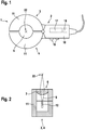
- FIGS. 1 . 5 and 6 show different embodiments of the hand laser tool 1 according to the invention for welding together not shown in the drawing thermoplastic pipes.
- the respective hand laser tool 1 has a tool housing 2 with two mutually movably fixed shell parts 3, 4, which are in the open state, the plastic pipes to be welded at least partially encompassing arranged.
- a plastic pipes receiving formed by the shell parts through opening 5 is formed. This is either adapted to the pipe diameter of the pipes to be welded or it is made for smaller pipes centering of the pipes to be welded.
- In the area of at least one of the shell parts 3, 4 is how the Figures 2-4 .
- a laser-based welding device 6 which has at least one optical Strahlformungs- and / or beam deflecting element 7, 8 for shaping or deflecting supplied laser beams 9, wherein the shaped and / or deflected laser beams 9, the plastic pipes to be welded with a predefinable Apply beam profile simultaneously or in rotation.
- the tool housing 2 is formed with a handle 10, wherein the handle 10 is attached to one of the shell parts 3, 4.
- the shell parts 3, 4 are therefore designed differently, whereas the shell part jaws 11 may be formed the same depending on the welding principle.
- the laser hand tool is scalable in size up to approx. 10 cm tube diameter.
- the two shell parts 3, 4 each have a shell-part jaw 11, wherein the first shell part 3 and its shell-part jaw 11 are fixed relative to the handle 10 and the other second shell part 4 and its shell-part jaw 11 up to preferably 60 -90 ° relative to the first shell part 3 and its shell part jaw 11 is formed pivotable.
- the shell part jaws 11 of the two shell parts 3, 4 are arranged diametrically opposite one another.
- Each of the shell parts 3, 4 of the hand laser tool 1 also has at least one laser-based welding device 6, which is designed to be stationary relative to the respective shell part 3, 4.
- the shell parts 3, 4 contain means for detecting the presence of components (pipes), include the radiation generation and cooling and provide a shielding of stray light.
- each of the laser-based welding device 6 preferably comprises a plurality of optical Strahlformungs- and / or beam deflecting elements 7, 8, which are arranged evenly distributed in the closed state of the shell parts 3, 4 over the circumference of the passage opening 5 and the plastic pipes, not shown, each having a preferably linear Simultaneously applied radially shaped laser beam, which overlap on the tubes.
- the laser beams 11 emanate from laser sources 12 which are integrated in the shell parts 3 and 4.
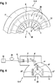
- the Figures 2 . 3 show a variant in which a plurality of single emitters are arranged as laser sources 12 in a row strip-shaped in the circumferential direction around the passage opening 5. These have a typical optical output of around 8 to 12 watts, which is linear in the fast-axis direction (FAC direction) by about 25 degrees half width width fanned laser beam 9 generate.
- the intensity distribution of the laser radiation is almost Gaussian in the fast-axis direction, and for an optimum low ripple, the sum of the intensity of the individual Gaussian intensity distribution of the radiated laser beam is an overlap of adjacent unit cells +/- 5%.
- the laser sources 12 are such aligned so that the emitted laser beam is directed to the center 22 of the passage opening 5. Downstream of the laser sources 12 is an imaging element as a beam-shaping element 7, which projects the laser beam 12 in the direction of the center point 22 and thus directs it perpendicular to the plastic pipes.
- an imaging element as a beam-shaping element 7, which projects the laser beam 12 in the direction of the center point 22 and thus directs it perpendicular to the plastic pipes.
- FIG. 2 which shows the corresponding shell part jaw 11 in cross-sectional starting position, only one laser source 12 and a beam-shaping element 7 is visible.
- FIG. 3 the shell part jaw 11 from FIG. 2 visualized in longitudinal section, it can be clearly seen that a number of laser sources 12 and beam shaping elements 7 is arranged in a circle around the passage opening 5 around.
- a laser source 12 and a beam-shaping element 7 are combined to form a unit cell 20, which is arranged in the circumferential direction of the shell member jaw 3 several times without spacing.
- the shell part jaw 4 is executed accordingly.
- the number of laser sources correspond to the tube diameter of the tubes to be welded, wherein twenty unit cells 20 are used in the embodiment for a 2.54 cm tube. For larger pipe diameters, more unit cells are used in proportion to the size in order to obtain the optical power per circumference. This has no negative impact on the homogeneity of the power distribution on the pipe.
- the focal length of the single-emitter laser source 12 can be adjusted so that the space per laser source 12 on a heat sink remains large enough and the homogeneity does not suffer from a coarser division of the laser source 12 on the full circle.
- a value of 1.5% should be achieved, manufacturing tolerances still have to be added between the single emitter laser sources 12, in order not to exceed a maximum intensity fluctuation of 7.5% prescribed for standard line lasers.
- Electric are in single-emitter laser sources 12 connected in series.
- Each shell part jaw 3,4 is, in the embodiment, made of solid copper as a support for the optical lenses and the laser source.
- the buffering of the waste heat from welding can be carried out in the respective cup-shaped part jaw 3, 4 made of copper.
- the cooling between the welds is preferably done by means of Peltier elements and air.
- Each single-emitter laser source 12 also acts as a single heat sink.
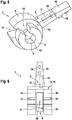
- the FIG. 4 shows another embodiment of the shell part 3 from FIG. 1 In a simultaneous fiber-coupled design with only one powerful remote laser source 12.
- the shell member jaw 11 has a plurality Strahlformungs- and beam deflecting elements 7, 8 on the one hand, the deflected laser beam 9 shape, divert and divide and so in the direction of the center 22 of the passage opening 5 while projecting with overlap on the tubes. From the laser source 12, the laser radiation via an optical fiber 23 to a focusing lens 7 ', then on a deflecting mirror 8' and on to a beam-expanding lens 7 ", and then to a beam splitter 8" out.
- the split laser beam 12 then falls on two deflecting mirrors 8 "', which reflect the respective laser beam 12 in the direction of the passage opening 5 and radially impinge the plastic tubes with overlapping laser radiation ', 8 ", 8'” the beam deflection elements 8 of the shell part jaw 11.
- the cylindrical lens 7 'in the axial device focuses the round beam of the optical fiber 23 to a line. With this cylindrical lens 7 'thus the weld seam width is defined.
- the shell part jaws 11 of each shell part 3, 4 are formed corresponding to each other.
- the shell parts 3, 4 has a laser-based welding device 6 which comprises optical beam shaping and / or beam deflection elements 7, 8.
- the two shell parts 3, 4 are each formed with a shell part mouth 13.
- the shell part 3, which has no laser-based welding device 6, is immovably connected to the tool housing 2 and thus also stationary relative to the handle 10.
- the other second shell part 4 and its shell part jaw 13 is rotatably arranged opposite the first shell part 3 and its shell part jaw 13, wherein the two shell part mouths 13 are arranged side by side laterally and the second shell part 4 and its shell part jaw 13 with respect to the first shell part 3 and its shell shell part 13 is rotatable by at least 360 °.
- the laser-based welding device 6 of the shell part 4 is acted upon in the closed state of the shell parts 3, 4, the non-pictured plastic pipes with a laser beam sequentially radially.
- the shell part 3 which has no laser-based welding device 6, immovably connected to the tool housing 2 and stationary relative to the handle 10, designed as a single head 14.
- the first fixed shell part 3 as a fork head shell part 15 with two fork shell shell segments 16, each having a shell part jaw 13, wherein the fork head shell part 15 and its shell part mouths 13 are fixed relative to the handle.
- the other second shell part 4 and its shell part jaw 13 are arranged between the two fork head shell part segments 16, so that the three shell part mouths 13 extend laterally offset next to one another.
- FIG. 7 shows the the laser source 12 and the Strahlformungs- and beam deflecting element 7, 8 having shell part 4 of the FIGS. 4 and 5 in longitudinal section.
- a diode laser with aspherical lens FAC
- the laser beam 9 is a mirror as a beam deflecting element 8 in the direction of acting as a beam shaping element 7 cylinder lens with about 10 mm Focussed focal length, which focuses the laser beam 9 perpendicular to the axis of rotation 21 of the shell part 4 to the fast-axis direction, which is arranged centrally in the passage opening 5.
- the diode laser 12 has a typical optical output power of about 40 watts and includes an array of laser diodes emitting laser light in a wavelength range of about 900 to 1000 nanometers.
- expert known cable length compensation means are arranged for the adaptation to the different cable length due to the rotational movement.
- a compressed air device for cooling the pipes to be welded
- the laser sources and / or the optical elements can be connected to the tool housing 2, inside the tool housing 2 guide channels and guide surfaces for guiding the compressed air to the cooling points are arranged. These are not visible from the outside.
- the hand laser tools 1 each have an integrated control and regulating device 17 in the tool housing 2 and actuating elements 18 on the tool housing 2, which are preferably arranged in or on the handle 10.
- measuring devices 19 for process control are arranged in the tool housing 2 of the manual laser tool 1 and connected to the control and regulating device 17.
Landscapes
- Physics & Mathematics (AREA)
- Engineering & Computer Science (AREA)
- Mechanical Engineering (AREA)
- Optics & Photonics (AREA)
- Health & Medical Sciences (AREA)
- Toxicology (AREA)
- Electromagnetism (AREA)
- Microelectronics & Electronic Packaging (AREA)
- Laser Beam Processing (AREA)
- Lining Or Joining Of Plastics Or The Like (AREA)
Abstract
Handlaserwerkzeug zum miteinander Verschweißen von thermoplastischen Kunststoffrohren, mit einem Werkzeuggehäuse (2) mit zwei aneinander gegenüber beweglich festgelegten Schalenteilen (3, 4), die im geöffneten Zustand die zu verschweißenden Kunststoffrohre wenigstens teilweise umgreifend anordenbar sind und im geschlossenen Zustand eine die Kunststoffrohre aufnehmende durch die Schalenteile (3, 4) geformte Durchtrittsöffnung (5) aufweisen, und wenigstens einer im Bereich der Schalenteile (3, 4) angeordneten laserbasierenden Schweißeinrichtung (6), die mindestens ein optisches Strahlformungs- und/oder Strahlumlenkungselement (7, 8) zum Formen bzw. Umlenken von zugeführten Laserstrahlen (9) aufweist, wobei die geformten und/oder umgelenkten Laserstrahlen (9) die zu verschweißenden Kunststoffrohre mit einem vorgebbaren Strahlprofil simultan oder rotierend beaufschlagen, und mit mindestens einem an dem Werkzeuggehäuse (2) befindlichen Handgriff (10). (Fig. 1)Hand laser tool for welding together thermoplastic plastic pipes, with a tool housing (2) with two shell parts (3, 4) which are movably fixed to one another and which, in the open state, can at least partially encompass the plastic pipes to be welded and, in the closed state, a plastic pipe receiving through the Shell parts (3, 4) have shaped passage opening (5), and at least one laser-based welding device (6) arranged in the region of the shell parts (3, 4) which has at least one optical beam shaping and / or beam deflection element (7, 8) for shaping or . Deflecting supplied laser beams (9), the shaped and / or deflected laser beams (9) impinging on the plastic pipes to be welded with a predeterminable beam profile simultaneously or rotating, and with at least one handle (10) located on the tool housing (2). (Fig. 1)
Description
Die Erfindung betrifft ein Handlaserwerkzeug zum Verschweißen von thermoplastischen Kunststoffrohren.The invention relates to a hand laser tool for welding thermoplastic pipes.
Das Verbinden der Enden von Rohren im Orbitalschweißverfahren ist aus dem Stand der Technik seit langem bekannt. Dabei werden die aneinander stoßenden oder sich überlappenden Rohrenden von zueinander ausgerichteten Rohren mittels unterschiedlichen Schweißverfahren, wie beispielsweise Laserdurchstrahlschweißen, Laser-Lichtbogenschweißen in Hybridtechnik oder Lichtbogenschweißen miteinander zu Rohrleitungen verbunden. Auf diese Weise können z.B. Rohre mit Wanddicken von 2 bis 20 mm und Durchmesser von 60 bis 1600 mm miteinander verschweißt werden. Zum Stand der Technik wird beispielhaft auf die Druckschriften
Rohrleitungen in Flugzeugen, Schiffen und Hausinstallationen werden aus Gewichts- und Kostengründen zunehmend aus Kunststoffen statt Metallwerkstoffen gefertigt. Bei erhöhten Anforderungen an die Qualität und Zuverlässigkeit der Rohrverbindungen bietet sich das Verschweißen mittels Laser an. Das Verbinden der Rohre im verbauten Zustand erfordert eine mobile Vorrichtung, die die Laserstrahlung simultan oder sequentiell auf den Rohrumfang richtet. Die aus dem Stand der Technik bekannten Vorrichtungen sind aufwändig an den Rohren zu befestigen, um eine Schweißnaht hoher Güte zu erreichen. Damit erfüllen diese nicht die Anforderungen hinsichtlich einer hohen Wirtschaftlichkeit sowie einer flexiblen Nutzung.For reasons of weight and cost, pipelines in aircraft, ships and domestic installations are increasingly made of plastics rather than metal materials manufactured. In the case of increased demands on the quality and reliability of the pipe connections, welding by means of laser offers itself. The connection of the pipes in the installed state requires a mobile device which directs the laser radiation simultaneously or sequentially on the pipe circumference. The devices known from the prior art are expensive to attach to the pipes in order to achieve a weld of high quality. Thus, these do not meet the requirements for high efficiency and flexible use.
Davon ausgehend liegt der Erfindung die Aufgabe zugrunde, eine Möglichkeit vorzuschlagen, mit der ein einfaches manuelles, jedoch teilautomatisiertes Schweißverfahren möglich ist, das zum Verbinden von Rohren bis ca. 10 cm Rohrdurchmesser eine einfache Handhabung auch bei schlecht zugänglichen Rohrleitungen erlaubt und die Anforderungen hinsichtlich Qualität und Wirtschaftlichkeit erfüllt.On this basis, the invention has for its object to propose a way by which a simple manual, but partially automated welding process is possible, which allows for connecting pipes up to 10 cm pipe diameter easy handling even with poorly accessible pipes and the requirements in terms of quality and economy fulfilled.
Diese Aufgabe wird erfindungsgemäß durch ein Handlaserwerkzeug mit den Merkmalen des unabhängigen Patentanspruchs 1 gelöst. Weitere vorteilhafte Ausgestaltungen der Erfindung sind den rückbezogenen Patentansprüchen zu entnehmen.This object is achieved by a hand laser tool with the features of
Kerngedanke der Erfindung ist es, ein handführbares, mit einem Handgriff versehenes Handlaserwerkzeug zu schaffen, das einschenklig oder zweischenklig ausgeführt und mindestens zwei die Rohre aufnehmende Schalenteile umfasst, von denen wenigstens eines eine laserbasierende Schweißeinrichtung aufweist, wobei die Schalenteile um eine Schwenk- oder Drehachse einander gegenüber derart lageveränderlich angeordnet sind, dass die Schalenteile und die Rohre senkrecht zueinander zusammenführbar sind.The core idea of the invention is to provide a hand-held, provided with a handle hand laser tool that is single-legged or two-legged and at least two tube-receiving shell parts, of which at least one has a laser-based welding device, wherein the shell parts about a pivot axis or rotation each other are arranged in such a variable position that the shell parts and the tubes are perpendicular to each other zusammenführbar.
Das Handlaserwerkzeug kann nicht nur von Hand geführt werden, sondern auch von einem Schweißroboter. Es wäre dann Teil einer stationären oder mobilen Maschine.The hand laser tool can be guided not only by hand, but also by a welding robot. It would then be part of a stationary or mobile machine.
Das erfindungsgemäße Handlaserwerkzeug zum miteinander Verschweißen von thermoplastischen Kunststoffrohren weist ein Werkzeuggehäuse mit zwei einander gegenüber beweglich festgelegten Schalenteilen auf, die im geöffneten Zustand in zu verschweißenden Kunststoffrohre wenigstens teilweise umgreifend anordenbar sind und im geschlossenen Zustand eine die Kunststoffrohre aufnehmende, durch die Schalenteile geformte Durchtrittsöffnung begrenzen. Erfindungsgemäß weist das Handlaserwerkzeug wenigstens eine im Bereich der Schalenteile angeordnete laserbasierende Schweißeinrichtung auf, die mindestens ein optisches Strahlformungs- und/oder Strahlumlenkungselement zum Formen bzw. Umlenken von zugeführten Laserstrahlen umfasst, wobei die geformten und/oder umgelenkten Laserstrahlen die zu verschweißenden Kunststoffrohre mit einem vorgebbaren Strahlprofil simultan oder rotierend beaufschlagen und an dem Werkzeuggehäuse des Handlaserwerkzeuges ein Handgriff zum Führen des Handlaserwerkzeuges vorgesehen ist. Das mindestens eine optische Strahlformungs- und/oder Strahlumlenkungselement beinhaltet je nach Ausbildung der Schweißeinrichtung beispielsweise optische Linsen, Strahlteiler, Umlenkspiegel. Dabei kann der dem Strahlformungs- bzw. Strahlumlenkungselement zugeführte Laserstrahl von einer Laserquelle ausgehen, die in oder an den Schalenteilen oder abgesetzt von diesen je nach erforderlicher Leistung im Werkzeuggehäuse oder fern vom Werkzeuggehäuse angeordnet ist. Falls die Laserquelle entfernt von dem optischen Strahlformungs- bzw. Strahlumlenkungselement angeordnet ist, so wird diesen der Laserstrahl vorzugsweise über einen Lichtwellenleiter vorzugsweise einen Glasfaserleiter zugeführt. Die Schweißeinrichtung selbst kann als Schweißeinrichtung mit je einer Gruppe von optischen Linsen, Strahlteiler und Umlenkspiegel in jedem Schalenteil, denen je ein Laserstrahl zugeführt wird oder eine Vielzahl von einzelnen Laseremittern aufweisend ausgebildet sein. Auch ist es möglich, mittels einer in einem Schalenteil um 360° oder mehr bewegten Laserquelle oder mittels einem bewegten Faserende einer Entfernung von dem Handwerkzeug befindlichen Laserquelle die Verschweißung durchzuführen. Der Handgriff kann sich dabei in Richtung des Werkzeuggehäuses oder quer dazu erstrecken und seitlich über das Gehäuse vorstehen oder in dieses versenkt sein. Es kann für das Verschweißen von sich stumpf stoßenden oder ineinander eingreifenden Rohrenden gleichermaßen verwendet werden.The hand laser tool according to the invention for welding thermoplastic pipes together has a tool housing with two oppositely movably fixed shell parts, which are at least partially encompassing in the open state in plastic pipes to be welded and in the closed state a plastic pipes receiving, formed by the shell parts defining passage opening. According to the invention, the hand laser tool has at least one laser-based welding device arranged in the region of the shell parts, which comprises at least one optical beam shaping and / or beam deflection element for shaping or deflecting supplied laser beams, the shaped and / or deflected laser beams having a predeterminable plastic pipe to be welded Apply beam profile simultaneously or rotating and on the tool housing of the hand laser tool, a handle for guiding the hand laser tool is provided. Depending on the design of the welding device, the at least one optical beam shaping and / or beam deflection element includes, for example, optical lenses, beam splitters, deflecting mirrors. In this case, the laser beam supplied to the beam shaping or beam deflection element can start from a laser source which is arranged in or on the shell parts or offset therefrom depending on the required power in the tool housing or far away from the tool housing. If the laser source is arranged away from the optical beam shaping or beam deflection element, the laser beam is preferably fed to it via an optical waveguide, preferably an optical fiber. The welding device itself can be designed as a welding device, each with a group of optical lenses, beam splitters and deflecting mirrors in each shell part, each of which a laser beam is supplied or a plurality of individual laser emitters having. It is also possible to carry out the welding by means of a laser source moved by 360 ° or more in a shell part or by means of a moving fiber end at a distance from the laser source located on the hand tool. The handle can move in the direction of the Tool housing or extend transversely thereto and protrude laterally beyond the housing or be recessed into this. It can equally be used for welding blunt abutting or intermeshing pipe ends.
Bei einer bevorzugten Ausführungsform der Erfindung weist jedes der Schalenteile des Handlaserwerkzeuges zumindest eine laserbasierende Schweißeinrichtung auf, die gegenüber dem jeweiligen Schalenteil feststehend ausgebildet ist, wobei jede laserbasierende Schweißeinrichtung ein, vorzugsweise mehrere, optische Strahlformungs- und/oder Strahlumlenkungselemente umfasst, die im geschlossenen Zustand der Schalenteile gleichmäßig über den Umfang der Durchtrittsöffnung verteilt angeordnet sind und die die Kunststoffrohre mit je einem Laserstrahl radial beaufschlagen. Diese spezielle Ausführungsform des erfindungsgemäßen Handlaserwerkzeuges ermöglicht eine simultane Verschweißung der thermoplastischen Kunststoffrohre.In a preferred embodiment of the invention, each of the shell parts of the hand laser tool has at least one laser-based welding device which is stationary relative to the respective shell part, wherein each laser-based welding device comprises one, preferably a plurality of optical beam shaping and / or beam deflection elements which in the closed state Shell parts are arranged distributed uniformly over the circumference of the passage opening and radially act on the plastic tubes, each with a laser beam. This special embodiment of the hand laser tool according to the invention enables a simultaneous welding of the thermoplastic plastic pipes.
Bei einer anderen vorteilhaften Ausführungsform der Erfindung weist nur eines der Schalenteile eine statische laserbasierende Schweißeinrichtung auf, die vorzugsweise optische Strahlformungs- und/oder Strahlumlenkungselemente umfasst, die im geschlossenen Zustand der Schalenteile um die Durchtrittsöffnung rotierbar angeordnet sind und die die Kunststoffrohre mit einem Laserstrahl radial beaufschlagen. Diese besondere Ausführungsform des erfindungsgemäßen Handlaserwerkzeuges ermöglicht die sequentielle orbitale Verschweißung der thermoplastischen Kunststoffrohre. Dabei kann der Laserstrahl ein oder mehrmals um die Kunststoffrohre herumgeführt werden, wobei beim mehrfachen Herumführen dies auch abwechselnd in entgegengesetzten Richtungen erfolgen kann.In another advantageous embodiment of the invention, only one of the shell parts on a static laser-based welding device, which preferably comprises optical Strahlformungs- and / or Strahlumlenkungselemente which are arranged rotatably in the closed state of the shell parts around the passage opening and radially act on the plastic pipes with a laser beam , This particular embodiment of the hand laser tool according to the invention enables the sequential orbital welding of the thermoplastic plastic pipes. In this case, the laser beam can be guided around the plastic pipes one or more times, and when repeatedly guided around, this can also take place alternately in opposite directions.
Bei einer bevorzugten Ausführungsform der Erfindung ist an dem Werkzeuggehäuse eine Drucklufteinrichtung zur Kühlung der zu verschweißenden Rohre, der Laserquellen und/oder der optischen Elemente anschließbar, wobei in dem Werkzeuggehäuse Leitkanäle und Leitflächen zur Führung der Druckluft zu den zu kühlenden Stellen angeordnet sind. Dies ermöglicht ein Verschweißen der thermoplastischen Kunststoffrohre mit hoher Leistung, ohne dass die Kunststoffrohre, die mindestens eine Laserquelle und/oder die optischen Elemente zur Strahlenformung und/oder Strahlumlenkung Schaden leiden. Das Werkzeuggehäuse besteht vorzugsweise aus gut wärmeleitenden Material und bildet eine Wärmesenke. Es wird vorzugsweise durch eine Luftströmung gekühlt, wobei auch andere Kühlmaßnahmen alternativ oder zusätzlich anwendbar sind. Mit dem Gehäuse wird auch der daran befindliche Handgriff gekühlt, so dass das Laserhandwerkzeug von dem Benutzer ohne Einschränkungen oder Verletzungsgefahr längere Zeit benutzt werden kann.In a preferred embodiment of the invention, a compressed air device for cooling the pipes to be welded, the laser sources and / or the optical elements can be connected to the tool housing, wherein in the tool housing guide channels and guide surfaces for guiding the compressed air are arranged to be cooled points. This allows welding of the high performance thermoplastic plastic tubes without damaging the plastic tubes, the at least one laser source, and / or the optical elements for beam shaping and / or beam deflection. The tool housing is preferably made of good heat conducting material and forms a heat sink. It is preferably cooled by an air flow, although other cooling measures are alternatively or additionally applicable. With the housing and the handle located thereon is cooled, so that the laser hand tool by the user without restrictions or risk of injury can be used for a long time.
Vorzugsweise weist das erfindungsgemäße Handlaserwerkzeug eine in dem Werkzeuggehäuse angeordnete Steuer- und Regelungseinrichtung sowie Betätigungselemente an dem Werkzeuggehäuse, vorzugsweise im Handgriff auf, mittels denen über übliche mechanische und oder elektromechanische Einrichtungen im Werkzeuggehäuse es möglich ist, die Schalenteile zu schließen, und nach dem durchgeführten Schweißvorgang die Schalenteile wieder zu öffnen und die zu verschweißenden Kunststoffrohre freizugeben. Über die Steuer- und Regeleinrichtung werden die zu verschweißenden Kunststoffrohre mit dem vorgebbaren Strahlprofil simultan oder rotierend beaufschlagt. Mit Strahlprofil ist hier nicht die räumliche Leistungsverteilung des Laserstrahls gemeint, sondern der zeitliche Verlauf der Laserleistung oder des Diodenstromes beim Schweißen. Außerdem ermöglicht dies ein automatisiertes Schweißverfahren, bei dem der mindestens eine Laserstrahl maschinell ohne Unterbrechung die Rohre um 360° simultan beaufschlagt oder ein oder mehrere Male sequentiell um 360° um die Rohre herumgeführt wird. Vorzugsweise sind dabei in dem Werkzeuggehäuse Messeinrichtungen zur Prozesskontrolle angeordnet und mit der Steuer- und Regeleinrichtung verbunden.Preferably, the hand laser tool according to the invention has a arranged in the tool housing control and regulating devices and actuators on the tool housing, preferably in the handle, by means of which conventional mechanical and or electromechanical devices in the tool housing, it is possible to close the shell parts, and after the performed welding to open the shell parts again and release the plastic pipes to be welded. About the control and regulating device to be welded plastic tubes with the predetermined beam profile are applied simultaneously or in rotation. With beam profile here is not the spatial power distribution of the laser beam meant, but the time course of the laser power or the diode current during welding. In addition, this enables an automated welding process in which the at least one laser beam is simultaneously applied to the pipes by 360 ° without interruption, or is guided one or more times sequentially through 360 ° around the pipes. Preferably, measuring devices for process control are arranged in the tool housing and connected to the control and regulating device.
Bei einer vorteilhaften Ausführungsform des erfindungsgemäßen Handlaserwerkzeuges formt das mindestens eine in dem Schalenteil angeordnete Strahlenformungs- und/oder Strahlumlenkungselement den jeweils von einer Laserquelle emittierten Laserstrahl vorzugsweise linienförmig und lenkt diesen auf die dem jeweiligen Schalenteil zugewandten Flächen der zu verschweißenden Kunststoffrohre ohne oder mit in einem Grenzbereich definierter Überlappung. Dies gilt sowohl für das simultane wie auch für die das sequentielle automatisierte Schweißverfahren. Die definierte Überlappung auf den dem jeweiligen Schalenteil zugewandten Flächen der zu verschweißenden Kunststoffrohre ist abhängig von dem Durchmesser und der Wandstärke der Kunststoffrohre. Bevorzugt wird dabei eine Ausführungsform, bei der das mindestens eine Strahlformungs- und Strahlumlenkungselement mit der jeweiligen Laserquelle fasergekoppelt ist. Die Laserstrahlung wird bei allen Ausführungsformen der Erfindung vorzugsweise zumindest den beweglichen Schalenteilen zugeführt. Dabei wird das von der Laserquelle ausgehende Laserlicht zunächst über eine biegesteife Glasfaser geleitet und dann nahe dem beweglichen Schalenteil in eine flexible Glasfaser umgekoppelt, die zum Schalenteil führt. Die flexible Glasfaser wird vorzugsweise über eine Spanneinrichtung in einer vorgegebenen Position gehalten.In an advantageous embodiment of the hand laser tool according to the invention, the at least one beam shaping and / or beam deflection element arranged in the shell part preferably forms the respective laser beam emitted by a laser source linearly and deflects it onto the surfaces of the surfaces facing the respective shell part to be welded Plastic pipes without or with an overlap defined in a boundary area. This applies to both the simultaneous and the sequential automated welding process. The defined overlap on the respective shell part facing surfaces of the plastic pipes to be welded depends on the diameter and the wall thickness of the plastic pipes. An embodiment in which the at least one beam shaping and beam deflection element is fiber-coupled to the respective laser source is preferred. The laser radiation is preferably supplied to at least the movable shell parts in all embodiments of the invention. In this case, the outgoing laser light from the laser source is first passed over a rigid glass fiber and then reversed near the movable shell part in a flexible glass fiber, which leads to the shell part. The flexible glass fiber is preferably held by a tensioning device in a predetermined position.
Vorzugsweise weisen bei einer Ausführungsform des Handlaserwerkzeuges die beiden Schalenteile eine Schalenteilbacke auf, wobei ein erstes Schalenteil und seine Schalenteilbacke gegenüber dem Handgriff feststehend ist und das andere zweite Schalenteil und seine Schalenteilbacke um bis zu vorzugsweise 60 bis 90° gegenüber dem ersten Schalenteil und seiner Schalenteilbacke verschwenkbar ausgebildet ist, wobei die beiden Schalenteilbacken einander diametral gegenüberliegend angeordnet sind. Damit ist das erfindungsgemäße Handlaserwerkzeug zangenförmig ausgebildet, wobei der Handgriff einen Zangenhebel bildet an dem das erste Schalenteil angeordnet ist und das zweite Schalenteil entweder an einem zweiten mit dem Werkzeuggehäuse schwenkbeweglich verbundenen zweiten Zangenhebel oder direkt an dem Werkzeuggehäuse schwenkbeweglich festgelegt ist. Bei einem vorhandenen zweiten Zangenhebel können die Schalenteile vom Benutzer manuell, ansonsten nur über eine in dem Gehäuse angeordnete Schließvorrichtung so zueinander positioniert werden, dass die Schalenteile eine geschlossene Durchtrittsöffnung für die Kunststoffrohre bilden.Preferably, in one embodiment of the hand laser tool, the two shell parts on a shell part jaw, wherein a first shell part and its shell part jaw is fixed relative to the handle and the other second shell part and its shell part jaw by up to preferably 60 to 90 ° relative to the first shell part and its shell part jaw pivoted is formed, wherein the two shell part jaws are arranged diametrically opposite one another. Thus, the hand laser tool according to the invention is designed pliers, wherein the handle forms a pliers lever on which the first shell part is arranged and the second shell part is fixed either on a second pivotally connected to the tool housing second pliers lever or directly to the tool housing pivotally. In the case of an existing second caliper lever, the shell parts can be positioned by the user manually, otherwise only via a closing device arranged in the housing, so that the shell parts form a closed passage opening for the plastic pipes.
Bei einer bevorzugten Ausführungsform dieser Variante sind an dem ersten und dem zweiten Schalenteil, die einander gegenüber verschwenkbar sind, mindestens je zwei Laserquellen sowie mindestens je ein zugehöriges Strahlformungs- und/oder Strahlumlenkungselement angeordnet, wobei der jeweilige Laserstrahl der Laserquelle zunächst direkt oder fasergekoppelt auf das im Bereich des Schalenteilmauls der Schalenteile angeordnete mindestens eine Strahlformungs- und/oder Strahlumlenkungselement fällt. Die Laserstrahlen sind dann jeweils hinter dem mindestens einen Strahlformungs- und/oder Strahlumlenkungselement auf die Kunststoffrohre vorzugsweise mit in einem Grenzbereich definierte Überlappung gerichtet. Günstigerweise sind bei einer Variante davon, die Laserquelle und das mindestens eine zugehörige Strahlformungs- und/oder Strahlumlenkungselement zu einer Einheitszelle zusammengeführt, wobei die Einheitszellen in der Umfangsrichtung der Durchtrittsöffnung fortlaufend angeordnet sind. Dies ermöglicht eine besonders einfache und effiziente sowie kostengünstige Ausführungsform des erfindungsgemäßen Handlaserwerkzeuges.In a preferred embodiment of this variant, at least on the first and the second shell part, which are pivotable relative to each other each two laser sources and at least one associated Strahlformungs- and / or Strahlumlenkungselement arranged, wherein the respective laser beam of the laser source initially directly or fiber-coupled to the arranged in the region of the shell part mouth of the shell parts at least one Strahlformungs- and / or Strahlumlenkungselement. The laser beams are then directed in each case behind the at least one beam-shaping and / or beam deflecting element on the plastic pipes, preferably with defined in a boundary region overlap. Conveniently, in a variant thereof, the laser source and the at least one associated beam-shaping and / or beam deflection element are combined to form a unit cell, wherein the unit cells are arranged continuously in the circumferential direction of the passage opening. This allows a particularly simple and efficient and cost-effective embodiment of the hand laser tool according to the invention.
Bei einer anderen bevorzugten Ausführungsform des erfindungsgemäßen Handlaserwerkzeuges weisen die beiden Schalenteile ein Schalenteilmaul auf, wobei ein erstes Schalenteil und sein Schalenteilmaul gegenüber dem Handgriff feststehend sind und das andere zweite Schalenteil und sein Schalenteilmaul gegenüber dem ersten Schalenteil und seinem Schalenteilmaul drehbeweglich angeordnet ist, wobei die beiden Schalenteilmäuler seitlich nebeneinander angeordnet sind und das zweite Schalenteil und sein Schalenteilmaul gegenüber dem ersten Schalenteil und seinen Schalenteilmaul um mindestens 360° rotierbar ausgebildet sind.In another preferred embodiment of the hand laser tool according to the invention, the two shell parts on a shell part mouth, wherein a first shell part and its shell part jaw are fixed relative to the handle and the other second shell part and its shell part mouth relative to the first shell part and its shell shell mouth is rotatably arranged, the two Shell part mouths are arranged side by side laterally and the second shell part and its shell part mouth are formed rotatable relative to the first shell part and its shell part mouth by at least 360 °.
Eine vorteilhafte Weiterbildung dieser Ausführungsform sieht vor, dass das erste Schalenteil als Gabelkopf-Schalenteil mit zwei Gabelkopf-Schalenteilsegmenten ausgebildet ist, die je ein Schalenteilmaul aufweisen, wobei das Gabelkopf-Schalenteil und seine Schalenteilmäuler gegenüber dem Handgriff feststehend sind und das andere zweite Schalenteil und sein Schalenteilmaul zwischen den beiden Gabelkopf-Schalenteilsegmenten angeordnet sind, wobei sich die drei Schalenteilmäuler seitlich nebeneinander angeordnet erstrecken. Das Kabelkopf-Schalenteil und seine Schalenteilmäuler sind gegenüber dem Handgriff feststehend. Das andere zweite Schalenteil und sein Schalenteilmaul sind gegenüber dem Gabelkopf-Schalenteil und seinen Schalenteilmäulern um mindestens 360° rotierbar ausgebildet ist.An advantageous development of this embodiment provides that the first shell part is designed as a clevis shell part with two clevis shell segments, each having a shell part mouth, the clevis shell part and its shell mouth parts are fixed relative to the handle and the other second shell part and Shell part mouth between the two fork head shell segments are arranged, wherein the three shell Teilmäuler laterally arranged side by side extend. The cable head shell part and its shell part mouths are fixed relative to the handle. The other second shell part and its shell part mouth are is formed rotatable about at least 360 ° relative to the fork head shell part and its shell part mouths.
Dabei ist bei den beiden vorstehend beschriebenen Varianten an dem Schalenteilmaul des zweiten Schalenteils, das gegenüber dem ersten Schaltenteil rotierbar ist, eine Laserquelle sowie mindestens ein Strahlformungs- und/oder Strahlumlenkungselement angeordnet, wobei der Laserstrahl senkrecht auf die Kunststoffrohre gerichtet ist. Der Laserquelle wird die Betriebsspannung günstigerweise über eine flexible Stromleitung zugeführt, die vorzugsweise über eine Spanneinrichtung in einer vorgegebenen Position gehalten ist. Zum Umfassen der Rohre muss das Schalenteilmaul des mittleren beweglichen Schalenteils gegenüber den angrenzenden Schalenteilmäulern des Gabelkopf-Schalenteil derart positioniert werden, dass ein durchgehender Einführspalt gebildet ist.In this case, in the two variants described above, a laser source and at least one beam shaping and / or beam deflection element are arranged on the shell part mouth of the second shell part, which is rotatable relative to the first switching part, wherein the laser beam is directed perpendicular to the plastic pipes. The laser source is advantageously supplied with the operating voltage via a flexible power line, which is preferably held in a predetermined position via a tensioning device. To encompass the tubes, the shell part mouth of the middle movable shell part must be positioned opposite the adjacent shell part mouths of the clevis shell part such that a continuous insertion gap is formed.
Bei dem vorgeschlagenen Handlaserwerkzeug handelt es sich um ein mobiles Kunststoffschweißgerät, das handführbar ist und mit dem nach dem Anlegen an die zu verbindenden Kunststoffrohre ein automatisierter Laserschweißvorgang durchführbar ist. Der Schweißvorgang kann nur gestartet werden, d.h. der Laser aktiviert werden, wenn die Durchtrittsöffnung der beiden Schalenteile geschlossen ist und zudem zu verschweißende Rohre darin aufgenommen sind. Das Werkzeug ist für unterschiedliche Rohrdurchmesser und Wandstärken einsetzbar bzw. daran mittels zugehöriger Adapterstücke anpassbar. Seine Größe und sein Gewicht sind derart bemessen, dass ein ermüdungsfreies Arbeiten über einen längeren Zeitraum möglich ist. Das Strahlprofil, mit dem die Kunststoffrohre beaufschlagt werden, ist vorgebbar bzw. veränderbar, so dass das Handlaserwerkzeug universell für die unterschiedlichsten thermoplastischen Kunststoffrohre einsetzbar ist.The proposed hand laser tool is a mobile plastic welding device that can be handled by hand and with which an automated laser welding process can be carried out after application to the plastic pipes to be connected. The welding process can only be started, i. the laser can be activated when the passage opening of the two shell parts is closed and, in addition, tubes to be welded are accommodated therein. The tool can be used for different pipe diameters and wall thicknesses or adaptable thereto by means of associated adapter pieces. Its size and weight are such that a fatigue-free working over a longer period is possible. The beam profile, with which the plastic pipes are acted upon, can be specified or changed, so that the hand laser tool can be used universally for a wide variety of thermoplastic plastic pipes.
Die vorstehend in der Beschreibung genannten Merkmale und Merkmalskombinationen, sowie die nachfolgend in der Figurenbeschreibung genannten und/oder in den Figuren allein gezeigten Merkmale und Merkmalskombinationen sind nicht nur in der jeweils angegebenen Kombination, sondern auch in anderen Kombinationen oder in Alleinstellung verwendbar Zur Ausführung der Erfindung müssen nicht alle Merkmale des Anspruchs 1 verwirklicht sein. Auch können einzelne Merkmale der unabhängigen oder nebengeordneten Ansprüche durch andere offenbarte Merkmale oder Merkmalskombinationen ersetzt werden.The features and combinations of features mentioned above in the description, as well as the features and feature combinations mentioned below in the description of the figures and / or alone in the figures, can be used not only in the respectively indicated combination but also in other combinations or alone. For carrying out the invention not all features of
Sämtliche aus den Ansprüchen, der Beschreibung oder der Zeichnung hervorgehenden Merkmale und/oder Vorteile, einschließlich konstruktive Einzelheiten, räumliche Anordnung und Verfahrensschritte können sowohl für sich als auch in den verschiedensten Kombinationen erfindungswesentlich sein. In den Figuren werden gleiche oder ähnliche Bauteile mit gleichen oder ähnlichen Bezugszeichen gekennzeichnet.All resulting from the claims, the description or the drawing features and / or advantages, including design details, spatial arrangement and method steps may be essential to the invention both in itself and in a variety of combinations. In the figures, the same or similar components are identified by the same or similar reference numerals.
Nachfolgend wird die Erfindung anhand mehrerer in der Zeichnung dargestellten Ausführungsbeispielen näher erläutert. Es zeigen in einer schematischen Darstellung:
Figur 1- ein erfindungsgemäßes Handlaserwerkzeug, das zangenartig ausgebildet ist und dessen beide Schalenteile eine Schalenteilbacke umfassen, in Seitenansicht;
Figur 2- eine erste Ausführungsform der Schalenteilbacke aus
Figur 1 mit integrierter Laserquelle, die eine Anzahl von Laserdioden und Strahlformungselemente aufweist, die in Umfangsrichtung gleichmäßig verteilt angeordnet sind und den Laserstrahl senkrecht auf die Rohre richten, in Querschnittsdarstellung; - Figur 3
- die
Schalenteilbacke aus Figur 2 in Längsschnittdarstellung; Figur 4- eine zweite Ausführungsform der Schalenteilbacke aus
Figur 1 mit abgesetzter Laserquelle, die eine Anzahl von Strahlformungs- und Strahlumlenkungselemente aufweist, die den zugeführten Laserstrahl aufteilen und mit Überlappung auf die Rohre projizieren, in Längsschnittdarstellung; Figur 5- ein erfindungsgemäßes Handlaserwerkzeug, das doppelklauenförmig ausgebildet ist, wobei die beiden Schalenteile ein Schalenteilmaul aufweisen und an einem der Schalenteile eine Laserquelle, Strahlformungs- und Strahlumlenkelemente angeordnet sind, in perspektivischer Darstellung;
Figur 6- ein erfindungsgemäßes Handlaserwerkzeug ähnlich der
Figur 5 , wobei eines der beiden Schalenteile als Gabelkopf-Schalenteil ausgebildet ist und das andere Schalenteil mit der Laserquelle, den Strahlformungs- und den Strahlumlenkelementen zwischen den Gabelkopf-Schalenteilsegmenten angeordnet ist, in perspektivischer Darstellung; und Figur 7- das Schalenteil mit der Laserquelle, den Strahlformungs- und dem Strahlumlenkungselement
aus den Figuren 4 und5 , in Längsschnittdarstellung.
- FIG. 1
- an inventive hand laser tool, which is formed like a pair of pliers and whose two shell parts comprise a shell part jaw, in side view;
- FIG. 2
- a first embodiment of the shell part jaw
FIG. 1 integrated laser source having a plurality of laser diodes and beam shaping elements uniformly distributed in the circumferential direction and directing the laser beam perpendicular to the tubes, in cross-sectional view; - FIG. 3
- the shell part jaw off
FIG. 2 in longitudinal section; - FIG. 4
- a second embodiment of the shell part jaw
FIG. 1 remote laser source comprising a plurality of beam shaping and beam redirecting elements which divide and feed the supplied laser beam onto the tubes with an overlap, in longitudinal section; - FIG. 5
- an inventive hand laser tool, which is formed double claw-shaped, wherein the two shell parts have a shell part mouth and on one of the shell parts a laser source, Strahlformungs- and Strahlumlenkelemente are arranged, in perspective view;
- FIG. 6
- an inventive hand laser tool similar to
FIG. 5 wherein one of the two shell parts is designed as a fork head shell part and the other shell part with the laser source, the beam shaping and the Strahlumungs- between the clevis shell segment segments is arranged, in perspective view; and - FIG. 7
- the shell part with the laser source, the beam shaping and the beam deflecting element of the
FIGS. 4 and5 , in longitudinal section.
Die
Bei der in der
Dabei gehen die Laserstrahlen 11 von Laserquellen 12 aus, die in die Schalenteile 3 und 4 integriert sind. Die
Die
Bei den in der
Bei der in der
Die
In allen vorstehend beschrieben Ausführungsbeispielen des Handlaserwerkzeuges 1 ist an das Werkzeuggehäuse 2 eine nicht dargestellte Drucklufteinrichtung zur Kühlung der zu verschweißenden Rohre, der Laserquellen und/oder der optischen Elemente anschließbar, wobei im Inneren des Werkzeuggehäuses 2 Leitkanäle und Leitflächen zur Führung der Druckluft zu den zu kühlenden Stellen angeordnet sind. Diese sind von außen nicht sichtbar. Zudem weisen die Handlaserwerkzeuge 1 jeweils eine integrierte Steuer- und Regeleinrichtung 17 in dem Werkzeuggehäuse 2 sowie Betätigungselemente 18 an dem Werkzeuggehäuse 2 auf, die vorzugsweise im bzw. am Handgriff 10 angeordnet sind. Des Weiteren sind im Werkzeuggehäuse 2 des Handlaserwerkzeuges 1 Messeinrichtungen 19 zur Prozesskontrolle angeordnet und mit der Steuer- und Regeleinrichtung 17 verbunden.In all embodiments of the
Claims (14)
Applications Claiming Priority (1)
| Application Number | Priority Date | Filing Date | Title |
|---|---|---|---|
| EP17209281 | 2017-12-21 |
Publications (1)
| Publication Number | Publication Date |
|---|---|
| EP3501803A1 true EP3501803A1 (en) | 2019-06-26 |
Family
ID=60813624
Family Applications (1)
| Application Number | Title | Priority Date | Filing Date |
|---|---|---|---|
| EP18156730.6A Withdrawn EP3501803A1 (en) | 2017-12-21 | 2018-02-14 | Handheld laser tool |
Country Status (1)
| Country | Link |
|---|---|
| EP (1) | EP3501803A1 (en) |
Cited By (1)
| Publication number | Priority date | Publication date | Assignee | Title |
|---|---|---|---|---|
| DE102020127922A1 (en) | 2020-10-23 | 2022-04-28 | Jenoptik Automatisierungstechnik Gmbh | Welding device for the simultaneous welding of socket connections of a plastic pipe system with at least one piece of pipe and one fitting |
Citations (4)
| Publication number | Priority date | Publication date | Assignee | Title |
|---|---|---|---|---|
| DE19804359A1 (en) * | 1997-02-05 | 1998-08-06 | Fluoroware Inc | Method and device for connecting thermoplastic pipe pieces |
| DE10334446A1 (en) | 2003-07-29 | 2005-02-17 | Orbitalservice Gmbh | Orbital welding device for welding processes comprises welding heads which move along a workpiece by means of a drive and guiding unit |
| WO2005056230A1 (en) | 2003-12-10 | 2005-06-23 | Vietz Gmbh | Orbital welding device for pipeline construction |
| DE102012007563B3 (en) | 2012-04-10 | 2013-05-29 | Salzgitter Mannesmann Line Pipe Gmbh | Apparatus for joining the ends of steel pipes by orbital welding |
-
2018
- 2018-02-14 EP EP18156730.6A patent/EP3501803A1/en not_active Withdrawn
Patent Citations (4)
| Publication number | Priority date | Publication date | Assignee | Title |
|---|---|---|---|---|
| DE19804359A1 (en) * | 1997-02-05 | 1998-08-06 | Fluoroware Inc | Method and device for connecting thermoplastic pipe pieces |
| DE10334446A1 (en) | 2003-07-29 | 2005-02-17 | Orbitalservice Gmbh | Orbital welding device for welding processes comprises welding heads which move along a workpiece by means of a drive and guiding unit |
| WO2005056230A1 (en) | 2003-12-10 | 2005-06-23 | Vietz Gmbh | Orbital welding device for pipeline construction |
| DE102012007563B3 (en) | 2012-04-10 | 2013-05-29 | Salzgitter Mannesmann Line Pipe Gmbh | Apparatus for joining the ends of steel pipes by orbital welding |
Cited By (3)
| Publication number | Priority date | Publication date | Assignee | Title |
|---|---|---|---|---|
| DE102020127922A1 (en) | 2020-10-23 | 2022-04-28 | Jenoptik Automatisierungstechnik Gmbh | Welding device for the simultaneous welding of socket connections of a plastic pipe system with at least one piece of pipe and one fitting |
| WO2022083820A1 (en) | 2020-10-23 | 2022-04-28 | Jenoptik Automatisierungstechnik Gmbh | Welding device for simultaneously welding socket joints of a pipeline system made of plastics material, which socket joints comprise at least one pipe section and a fitting |
| DE102020127922B4 (en) | 2020-10-23 | 2023-04-27 | Jenoptik Automatisierungstechnik Gmbh | Welding device for the simultaneous welding of socket connections of a plastic pipe system with at least one piece of pipe and one fitting |
Similar Documents
| Publication | Publication Date | Title |
|---|---|---|
| EP1773534B2 (en) | Laser device and operating method | |
| EP2322311B1 (en) | Device for laser spot welding | |
| EP2302433B1 (en) | Laser machining head with drawer for holding a lens | |
| EP2492043B1 (en) | Joint method and device | |
| EP2291259B1 (en) | Contact tube for a welding torch | |
| DE8026897U1 (en) | Laser beam device for fusion and flame cutting | |
| EP0993345B1 (en) | Laser-assisted bending method | |
| EP3746258B1 (en) | Gas supply device and laser processing head comprising same | |
| EP2416918A1 (en) | Method and device for connecting the ends of steel tubes by means of orbital welding using a hybrid technique | |
| EP3404786B1 (en) | Laser cutting apparatus for shielded lines and method for laser cutting of shielded lines comprising such a laser cutting apparatus | |
| WO2019233944A1 (en) | Device for laser machining workpieces that are difficult to access | |
| DE19841040A1 (en) | Marking appliance for e.g. metal surface | |
| WO2020098868A1 (en) | Device for laser cutting shielded conductors, and method for laser cutting shielded conductors using a laser cutting device of this kind | |
| EP3501803A1 (en) | Handheld laser tool | |
| DE102008063614B4 (en) | Laser arc hybrid welding head | |
| EP3031539B1 (en) | Turning device | |
| DE202004013136U1 (en) | Modular optical waveguide lens system esp. for laser optics having a main carrier with a connector and exchangeable lens module | |
| EP2468445B1 (en) | Laser processing machine with a diode laser, which laser beam can rotate around its axis, and method of machining a workpiece | |
| EP3746259B1 (en) | Gas supply device and laser processing head comprising same | |
| DE102017201731A1 (en) | Welding apparatus for electric resistance spot welding and method | |
| DE102009018915A1 (en) | Multi-beam laser processing head to process laser material, comprises beam divider, focusing device, and material feeding device formed as wire-/powder feeder, where the head is designed to divide input laser beam into initial laser beams | |
| EP1927422B1 (en) | Welding head for welding non-rotation symmetrical parts to workpieces | |
| DE102016208131A1 (en) | Method and device for machining a workpiece | |
| EP3153272A1 (en) | Welding device for resistance projection welding | |
| DE69516992T2 (en) | Additional bending method for Corrigeren curved workpieces and information detection device for additional bending of workpieces |
Legal Events
| Date | Code | Title | Description |
|---|---|---|---|
| PUAI | Public reference made under article 153(3) epc to a published international application that has entered the european phase |
Free format text: ORIGINAL CODE: 0009012 |
|
| AK | Designated contracting states |
Kind code of ref document: A1 Designated state(s): AL AT BE BG CH CY CZ DE DK EE ES FI FR GB GR HR HU IE IS IT LI LT LU LV MC MK MT NL NO PL PT RO RS SE SI SK SM TR |
|
| AX | Request for extension of the european patent |
Extension state: BA ME |
|
| STAA | Information on the status of an ep patent application or granted ep patent |
Free format text: STATUS: THE APPLICATION IS DEEMED TO BE WITHDRAWN |
|
| 18D | Application deemed to be withdrawn |
Effective date: 20200103 |