EP3501757B1 - Aufbewahrungsvorrichtung mit verriegelungsmechanismus - Google Patents
Aufbewahrungsvorrichtung mit verriegelungsmechanismus Download PDFInfo
- Publication number
- EP3501757B1 EP3501757B1 EP18206799.1A EP18206799A EP3501757B1 EP 3501757 B1 EP3501757 B1 EP 3501757B1 EP 18206799 A EP18206799 A EP 18206799A EP 3501757 B1 EP3501757 B1 EP 3501757B1
- Authority
- EP
- European Patent Office
- Prior art keywords
- bin
- organizer
- locking
- closed position
- fully closed
- Prior art date
- Legal status (The legal status is an assumption and is not a legal conclusion. Google has not performed a legal analysis and makes no representation as to the accuracy of the status listed.)
- Active
Links
Images


Classifications
-
- B—PERFORMING OPERATIONS; TRANSPORTING
- B25—HAND TOOLS; PORTABLE POWER-DRIVEN TOOLS; MANIPULATORS
- B25H—WORKSHOP EQUIPMENT, e.g. FOR MARKING-OUT WORK; STORAGE MEANS FOR WORKSHOPS
- B25H3/00—Storage means or arrangements for workshops facilitating access to, or handling of, work tools or instruments
- B25H3/02—Boxes
- B25H3/021—Boxes comprising a number of connected storage elements
- B25H3/022—Boxes comprising a number of connected storage elements in fixed relationship
-
- E—FIXED CONSTRUCTIONS
- E05—LOCKS; KEYS; WINDOW OR DOOR FITTINGS; SAFES
- E05B—LOCKS; ACCESSORIES THEREFOR; HANDCUFFS
- E05B65/00—Locks or fastenings for special use
- E05B65/46—Locks or fastenings for special use for drawers
- E05B65/462—Locks or fastenings for special use for drawers for two or more drawers
-
- E—FIXED CONSTRUCTIONS
- E05—LOCKS; KEYS; WINDOW OR DOOR FITTINGS; SAFES
- E05Y—INDEXING SCHEME ASSOCIATED WITH SUBCLASSES E05D AND E05F, RELATING TO CONSTRUCTION ELEMENTS, ELECTRIC CONTROL, POWER SUPPLY, POWER SIGNAL OR TRANSMISSION, USER INTERFACES, MOUNTING OR COUPLING, DETAILS, ACCESSORIES, AUXILIARY OPERATIONS NOT OTHERWISE PROVIDED FOR, APPLICATION THEREOF
- E05Y2999/00—Subject-matter not otherwise provided for in this subclass
Definitions
- This application relates to an organizer, and more specifically to a flip bin organizer having a plurality of bins that are pivotally engaged to the organizer.
- the flip bin organizer further includes a locking mechanism that is configured to selectively lock the bins in their fully closed position.
- Organizers are well known. They are commonly used to separate and transport a variety of small accessories, such as screws, nuts, bolts, washers, etc. Organizers typically have a housing and a plurality of bins. Each bin is typically dedicated to a single item and tradespersons are constantly moving between the bins to find and use the appropriate accessory.
- EP 2308655A2 discloses a container configured to transport articles.
- the container includes storage bins that can be locked by a latch.
- US 2002/027403 A1 discloses drop-in bin containers disposed in a housing.
- the drop-in bins are configured to pivot outwardly from the housing.
- the housing includes a clip for holding the bins in their closed position.
- US 2005/241973 A1 discloses an apparatus for transporting power tools and their accessories.
- the apparatus includes a closable case having a work surface and storage compartments.
- the disclosed storage compartments are tilt-out bins that can be closed by rotatable toggles.
- US 5,069,342 A discloses a container that is a combination tool box and organizer.
- the organizer section includes at least two shelves each having two bins.
- the shelves also have protector covers that can be locked in a closed position.
- the present invention relates to an organizer including a housing having one or more compartments for receiving a bin.
- the organizer also includes a first bin disposed in a compartment and comprising a front panel, a back panel, a right side panel, a left side panel, and a bottom panel all of which define an interior portion, wherein said first bin is pivotally attached within the compartment, and is configured to reciprocally move between an open position, a first closed position and a fully closed position, wherein the first closed position is between the open position and the fully closed position, and wherein in the open position, access to the interior portion is unimpeded, and in the first closed position, access to the interior portion is impeded, but the bin is not lockable, and in the fully closed position access to the interior portion is impeded and the bin may selectively be locked in position.
- the organizer also includes a locking mechanism for selectively locking one or more bins in their fully closed position, wherein said locking mechanism is configured to reciprocally move between an unlocked position and a locked position.
- a bin In the unlocked position, a bin may freely move between its open position and its fully closed position.
- a bin in its fully closed position In the locked position, a bin in its fully closed position is locked in place, and a bin in its open position or its first closed position, is freely movable between said positions.
- a bin in its first closed position may be moved to the fully closed position at which point it will become locked in place.
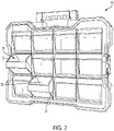
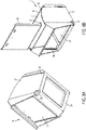
- an embodiment of an organizer 10 includes a housing 12 having one or more compartments 14. Housing 12 may be a single enclosure or it may include a removable back portion 13. Each compartment 14 is configured to receive a bin 16.
- Bin 16 includes a front panel 18, a back panel 20, a left side panel 22, a right side panel 24, and a bottom panel 26. The panels of bin 16 define an interior space 28 that may be suitable for holding a variety of small accessories such as nuts, bolts, screws, and washers (not shown).
- the front panel 18 of bin 16 may be transparent to allow for visual access to the interior space 28. In an alternate embodiment, as shown in Figs 3 and 8(b) , the front panel 18 may also be removable from the bin 16.
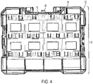
- each bin 16 is configured to move within its compartment 14 between an open position and a fully closed position. In the open position, access to the interior space 28 is unimpeded. In the fully closed position, access to the interior space 28 is impeded and, as will be discussed below, the bin 16 may be selectively locked in this fully closed position. To accomplish the movement between the open position and the fully closed position, it is preferable for the bin 16 to be pivotally attached within its compartment 14.
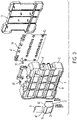
- Each compartment may include a bin engagement protrusion 30.
- each bin 16 may include a bin engagement protrusion receiving portion 32.
- the bin engagement protrusions 30 engage the bin engagement protrusion receiving portions 32 and allow the bin to pivot within the compartment 14 between an open and fully closed position.
- the bin engagement protrusions 30 may be selectively disengaged from their respective bin engagement receiving portions thus allowing the entire bin 16 to be removed from the compartment 14 and housing 12.
- each compartment 14 may further include a bin stop protrusion 34.
- the bin stop protrusion 34 which may preferably have an angled orientation, is configured to engage a bin stop engagement portions 36.
- the bin stop engagement portion 36 may be a small hook shaped protrusion on the exterior of either the left side panel 22 or right side panel 24 of the bin 16.
- each compartment 14 may also contain an arcuate roof 44.
- the arcuate nature of roof 44 is configured to closely match the arcuate upper edges 40, 42.
- the arc of roof 44 closely matches the arc that upper edge 38 travels as the bin 16 pivots from its fully closed position to it open position.
- Locking mechanism 46 comprises a locking switch 48, a locking arm 50, a locking plate 52, and at least one spring 54.
- the components of locking mechanism 46 are configured to move between a unlocked position and a locked position. In the unlocked position, each bin 16 of the organizer 10 is freely movable between its open position and its fully closed position. When the locking mechanism 46 is in its closed position, each bin 16 that is in its fully closed position becomes securely locked in place. However, bins 16 that are in the open position may freely move between said open position and a first closed position. In this first closed position, which is in between the open position and fully closed position, access to the interior portion 28 is impeded but the bin 16 is not lockable.
- locking mechanism 46 If the locking mechanism 46 is in its locked position and bin 16 is in the first closed position, if so desired, the bin 16 may be moved into its fully closed position where it will become locked in place. As will be shown below, locking mechanism 46 can accomplish this without unlocking any other bins 16 that are already locked in their fully closed position.
- the locking switch 48 of locking mechanism 46 is accessible from the exterior of the housing 12.
- Locking switch 48 is configured to move between a first position and a second position, wherein the first position coincides with the unlocked position of locking mechanism 46 and the second position coincides with the unlocked position of the locking mechanism 46.
- the locking switch 48 may be handle.
- locking switch 48 could also be a slide or lever.
- Locking switch 48 is connected to locking arm 50.
- Locking arm 50 may be disposed within the housing 12 and may not be generally accessible except through the locking switch 48. As shown in Fig 3 , the locking switch 48 and locking arm 50 may be separate parts. However, those skilled in the art will recognize that that the locking switch 48 and locking arm 50 may be formed such that they are integral to one another.
- Locking arm may generally comprise a horizontal portion 56 and a ramp portion 58. An outer edge 60 of the ramp portion 58 may be configured to engage the locking plate 52.
- locking plate 52 is configured to move between a first position and a second position, wherein the first position coincides with the unlocked position of the locking mechanism 46 and the second position coincides with the locked position of the locking mechanism 46.
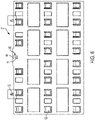
- locking plate 52 may include a plurality of bin engaging protrusions 62.
- the locking plate 52 may also include two locking arm protrusions 64.
- Locking arm protrusions 64 define a space 66 there between. Space 66 is configured to receive the outer edge 60 of the ramp portion 58 of locking arm 50.
- the locking mechanism 46 may also include one or more springs 54.
- Spring 54 may be disposed between the housing 12 and the locking plate 52.
- Locking plate 52 may also include one or more spring receiving portions 68.
- Spring 54 may bias the locking plate 52 toward its second position.
- organizer 10 of the present application may also include a back-to-back latch 78 that is configured to engage a latch engaging region 80 on another organizer. When engaged, the back-to-back latch permits two organizers to be secured to one another such that the bins 16 from both organizers are accessible simultaneously.
- organizer 10 may also include one or more stacking latches 82. Stacking latches 82 may be configured to engage latch engaging regions 80 on adjacent containers or items such that the organizer 10 can be in stacking engagement therewith.
- a handle 84 may be included to allow for easy transportation of the organizer 10.
- any of the components discussed in the organizer of the present application may be formed from any appropriate material in various embodiments, including metals, plastics, and combinations thereof. Additionally, in some embodiments components described above may be assemblies of subcomponents. Additionally, various components may be formed integral to one another. Assemblies of components together may be by any appropriate mechanism, including but not limited to adhesion, welds, snap fit, and fastening with fasteners (including but not limited to bolts, screws, rivets, etc.). Other modifications to the disclosure herein provided may be understood as being within the scope of claims enabled by this disclosure.
- the locking mechanism 46 is configured to move between an unlocked and a locked position.
- the locking switch 48 may be in its first position.
- the locking arm 50 which is connected to the locking arm 48, is positioned such that the outer edge 60 of ramp portion 58 is engaged to the locking plate 52 at a high end 70 of the ramp portion 58.
- the entirety of the locking plate 52 is moved against the bias of spring 54 and toward its first position.
- each bin engaging protrusion 62 is lifted out of contact with the back panel 20 of bin 16.
- bin 16 is freely movable between its fully closed position and its open position.
- the locking switch 48 is toggled to its second position.
- the locking arm 50 which is connected to the locking switch 48, is oriented such that a low end 72 of the ramp portion 58 is engaged to the locking plate 52.
- the entirety of the locking plate 52 is moved toward its second position. In this second position, each bin engaging protrusion 62 is moved downward such that it is in locking engagement with the back panel 20 of any bin 16 that is in the fully closed position.
- a bin 16 When the locking mechanism 46 is in its locked position, a bin 16 may be its open position. If this occurs, bin 16 will be free to move between the open position and the first closed position, wherein the back panel 20 may be in contact with the bin engaging protrusion 62 of the locking plate 52, but not in locking engagement therewith. Instead, the back panel may merely lean against a tapered face 74 of the bin engaging protrusion 62.
- Bin engaging protrusion 62 may also include a flexible arm 76. The tapered face 74 and flexible arm 76 of the bin engaging protrusion allow for a bin 16 to move from the first closed position to the fully closed position, without unlocking any other bins from their fully closed position.
- a bin 16 is able to move between its first closed position and its fully closed position without unlocking any other bins that may already be secured in their fully closed position.
Landscapes
- Engineering & Computer Science (AREA)
- Mechanical Engineering (AREA)
- Closures For Containers (AREA)
- Supports Or Holders For Household Use (AREA)
- Packaging Of Annular Or Rod-Shaped Articles, Wearing Apparel, Cassettes, Or The Like (AREA)
Claims (13)
- Organisator (10), umfassend:ein Gehäuse (12) mit zwei oder mehr Fächern (14) zum Aufnehmen eines Behälters;einen ersten Behälter (16) und einen zweiten Behälter (16), die jeweils in einem separaten Fach (14) angeordnet sind,und wobei jeder Behälter eine vordere Platte (18), eine hintere Platte (20), eine rechte Seitenplatte (24), eine linke Seitenplatte (22) und eine untere Platte (26) umfasst, die alle einen inneren Abschnitt (28) definieren, wobei jeder Behälter innerhalb eines Fachs (14) schwenkbar befestigt ist und konfiguriert ist, um sich zwischen einer offenen Position, einer ersten geschlossenen Position und einer vollständig geschlossenen Position zu bewegen, wobei die erste geschlossene Position zwischen der offenen Position und der vollständig geschlossenen Position ist, und wobei in der offenen Position der Zugang zum inneren Abschnitt (28) ungehindert ist und in der ersten geschlossenen Position der Zugang zum inneren Abschnitt (28) verhindert ist, aber der Behälter (16) nicht verriegelbar ist, und in der vollständig geschlossenen Position der Zugang zum inneren Abschnitt (28) verhindert ist und der Behälter selektiv in seiner Position verriegelt sein kann; undeinen Verriegelungsmechanismus (46), der konfiguriert ist, um den ersten und den zweiten Behälter (16) selektiv in seiner jeweiligen vollständig geschlossenen Position zu verriegeln, wobei der Verriegelungsmechanismus (46) konfiguriert ist, um sich zwischen einer entriegelten Position und einer verriegelten Position hin- und herzubewegen,wobei sich in der entriegelten Position jeder von dem ersten und dem zweiten Behälter (16) frei zwischen seiner jeweiligen offenen Position und seiner jeweiligen vollständig geschlossenen Position bewegen kann,wobei in der verriegelten Position jeder von dem ersten und dem zweiten Behälter (16), der sich in seiner vollständig geschlossenen Position befindet, an Ort und Stelle verriegelt ist, und jeder von dem ersten und zweiten Behälter (16), der sich in seiner offenen Position oder seiner ersten geschlossenen Position befindet, frei beweglich zwischen der offenen Position und der ersten geschlossenen Position ist, und wobei jeder von dem ersten und dem zweiten Behälter (16), der sich in seiner ersten geschlossenen Position befindet, in seine jeweilige vollständig geschlossene Position bewegt werden kann, wo er an Ort und Stelle verriegelt wird,wobei, wenn sich der Verriegelungsmechanismus (46) in der verriegelten Position befindet und sich der erste Behälter (16) in seiner vollständig geschlossenen Position befindet, der zweite Behälter (16) von seiner ersten geschlossenen Position in seine vollständig geschlossene Position bewegt werden kann, ohne den ersten Behälter (16) aus seiner vollständig geschlossenen Position zu entriegeln; unddadurch gekennzeichnet, dass der Verriegelungsmechanismus (46) Folgendes umfasst:einen Verriegelungsschalter (48), der von der Außenseite des Gehäuses (12) zugänglich ist und zwischen einer ersten Position und einer zweiten Position hin- und herbewegbar ist, wobei die erste Position der entriegelten Position des Verriegelungsmechanismus (46) entspricht und die zweite der verriegelten Position des Verriegelungsmechanismus (46) entspricht;einen Verriegelungsarm (50), der mit dem Verriegelungsschalter (48) verbunden ist;eine Verriegelungsplatte (52), die eine Vielzahl von Behältereingriffsvorsprüngen (62) umfasst, die jeweils eine sich verjüngende Fläche (74) und einen flexiblen Arm (76) umfasst, und wobei die Verriegelungsplatte (52) konfiguriert ist, um mit dem Verriegelungsarm (50) in Eingriff zu kommen und zwischen einer ersten Position und einer zweiten Position hin- und herbewegbar zu sein, wobei die erste Position der unverriegelten Position des Verriegelungsmechanismus (46) entspricht und die zweite Position der verriegelten Position des Verriegelungsmechanismus (46) entspricht; undeine Vorspannfeder (54), konfiguriert zum Vorspannen der Verriegelungsplatte (52) in Richtung der zweiten Position.
- Organisator (10) nach Anspruch 1, wobei die Verriegelungsplatte (52) weiter Verriegelungsarmvorsprünge (64) einschließt, die dazwischen einen Raum (66) definieren; und wobei der Verriegelungsarm (50) weiter einen rampenförmigen Abschnitt (58) einschließt, dessen Kante in dem Raum angeordnet ist, der durch die Verriegelungsarmvorsprünge (64) der Verriegelungsplatte (52) definiert ist, und konfiguriert ist, um in Gleiteingriff damit zu sein; und
wobei, wenn sich der Verriegelungsschalter (48) in seiner ersten Position befindet, der rampenförmige Vorsprung (58) des Verriegelungsarms (50) die Verriegelungsplatte (52) in ihrer ersten Position hält; und wenn sich der Verriegelungsschalter (48) in seiner zweiten Position befindet, der rampenförmige Vorsprung (58) die Verriegelungsplatte (52) in ihrer zweiten Position hält. - Organisator (10) nach Anspruch 1, wobei die Behältereingriffsvorsprünge (62) der Verriegelungsplatte (52) einen flexiblen Arm (76) und mindestens eine sich verjüngende Fläche (74) einschließen.
- Organisator nach Anspruch 3, wobei der Verriegelungsschalter (48) und der Verriegelungsarm (50) integriert sind.
- Organisator (10) nach Anspruch 4, wobei jedes Fach (14) des Gehäuses (12) weiter ein bogenförmiges Dach (44) einschließt, das konfiguriert ist, um den inneren Abschnitt (28) eines Behälters (16) zu bedecken, der innerhalb des Fachs (14) angeordnet ist.
- Organisator (10) nach Anspruch 5, weiter umfassend einen Griff (84), der mit dem Gehäuse (12) in Eingriff steht und konfiguriert ist, um zu ermöglichen, dass der gesamte Organisator (10) davon getragen wird.
- Organisator (10) nach Anspruch 6, weiter umfasst eine Rücken-an-Rücken-Sperre (78) und einen Sperreneingriffsbereich (80).
- Organisator (10) nach Anspruch 7, weiter umfasst eine Stapelsperre (82).
- Organisator (10) nach Anspruch 1, wobei der erste Behälter (16) eine selektiv entfernbare Frontplatte (18) einschließt.
- Organisator (10) nach Anspruch 9, wobei der erste Behälter (16) eine transparente Frontplatte (18) einschließt.
- Organisator (10) nach Anspruch 1, wobei der erste Behälter (16) selektiv von dem Gehäuse (12) entfernbar ist.
- Organisator (10) nach Anspruch 1, wobei das Fach (14) des Gehäuses (12) weiter mindestens einen Behälterstoppervorsprung (34) einschließt; und der erste Behälter (16) mindestens einen Behälterstopper-Eingriffsabschnitt (36) einschließt, der konfiguriert ist, um mit dem Behälterstoppervorsprung (34) in Eingriff zu kommen und ermöglicht, dass der erste Behälter (16) in seiner offenen Position gehalten wird, ohne aus dem Organisator (10) zu fallen.
- Organisator (10) nach Anspruch 1, wobei das Fach (14) weiter mindestens einen Behältereingriffsvorsprung (30) einschließt; und der erste Behälter (16) mindestens einen Behältereingriffsvorsprung-Aufnahmeabschnitt (32) einschließt, der konfiguriert ist, um zu ermöglichen, dass der Behälter (14) darauf geschwenkt wird.
Applications Claiming Priority (1)
| Application Number | Priority Date | Filing Date | Title |
|---|---|---|---|
| US201762587553P | 2017-11-17 | 2017-11-17 |
Publications (2)
| Publication Number | Publication Date |
|---|---|
| EP3501757A1 EP3501757A1 (de) | 2019-06-26 |
| EP3501757B1 true EP3501757B1 (de) | 2022-12-28 |
Family
ID=64362355
Family Applications (1)
| Application Number | Title | Priority Date | Filing Date |
|---|---|---|---|
| EP18206799.1A Active EP3501757B1 (de) | 2017-11-17 | 2018-11-16 | Aufbewahrungsvorrichtung mit verriegelungsmechanismus |
Country Status (3)
| Country | Link |
|---|---|
| US (1) | US10406673B2 (de) |
| EP (1) | EP3501757B1 (de) |
| CN (1) | CN109795772B (de) |
Families Citing this family (13)
| Publication number | Priority date | Publication date | Assignee | Title |
|---|---|---|---|---|
| IL269564B2 (en) | 2019-09-23 | 2023-11-01 | Keter Home & Garden Products Ltd | Sawhorse |
| FR3105188B1 (fr) * | 2019-12-18 | 2021-12-10 | Julien Pruvost | Panneau de construction, kit associé et objet modulable associé |
| JP1707300S (ja) | 2021-08-24 | 2022-02-10 | 工具用ケース | |
| DE112023000317T5 (de) | 2022-01-21 | 2024-10-17 | Milwaukee Electric Tool Corporation | Modulare aufbewahrungseinheit einschliesslich untereinheiten |
| DE112023000457T5 (de) | 2022-03-22 | 2024-10-17 | Milwaukee Electric Tool Corporation | Verschiebbare stützstruktur für modulare einheiten |
| USD1063376S1 (en) | 2022-06-08 | 2025-02-25 | Yeti Coolers, Llc | Container |
| USD1024557S1 (en) | 2022-06-08 | 2024-04-30 | Yeti Coolers, Llc | Container |
| US11912477B2 (en) | 2022-06-08 | 2024-02-27 | Yeti Coolers, Llc | Container with handle and latching system |
| USD1036116S1 (en) | 2022-06-08 | 2024-07-23 | Yeti Coolers, Llc | Container |
| US20240049878A1 (en) * | 2022-08-12 | 2024-02-15 | Techtronic Cordless Gp | Parts organizer |
| US12097995B2 (en) * | 2022-11-29 | 2024-09-24 | Deflecto, LLC | Customizable caddy for tilt bins |
| USD1036119S1 (en) | 2022-11-30 | 2024-07-23 | Yeti Coolers, Llc | Container |
| WO2025141574A1 (en) | 2023-12-28 | 2025-07-03 | Keter Home and Garden Products Ltd. | Bin organizer and locking mechanism therefor |
Family Cites Families (21)
| Publication number | Priority date | Publication date | Assignee | Title |
|---|---|---|---|---|
| US5069342A (en) | 1990-08-13 | 1991-12-03 | Contico International, Inc. | Combination tool box/organizer |
| JPH07301042A (ja) * | 1994-05-09 | 1995-11-14 | Ricoh Co Ltd | チルト機構を備えた電子機器 |
| US20020027403A1 (en) | 1999-10-22 | 2002-03-07 | Vasudeva Kailash C. | Drop-bin containers and holders for same |
| US6626295B1 (en) * | 2000-03-30 | 2003-09-30 | Maxtech Manufacturing Inc | Tool case with snap-in modules |
| US20030168952A1 (en) * | 2002-03-08 | 2003-09-11 | Ching-Yang Huang | Activating device to open all the boxes of tool box |
| US20040012314A1 (en) | 2002-07-17 | 2004-01-22 | Hay Michael E. | Removable tilting bin system |
| WO2005107516A2 (en) | 2004-05-03 | 2005-11-17 | Nomis, Llc | Work center/clamping table and storage system |
| US7228966B1 (en) * | 2004-05-07 | 2007-06-12 | Darlene Turner | Portable lipstick carrying case |
| US7513364B2 (en) * | 2004-10-29 | 2009-04-07 | Gau Woei Super Hard Tool Co., Ltd. | Casing with a locking unit |
| US20070062831A1 (en) * | 2005-09-21 | 2007-03-22 | Chang-Ying Chen | Safety switch of a toolbox |
| US7784887B2 (en) * | 2007-03-21 | 2010-08-31 | Larry Mitchell Grela | Toolbox assembly |
| JP2009022543A (ja) * | 2007-07-20 | 2009-02-05 | Okamura Corp | 多段式キャビネット |
| US20090223971A1 (en) * | 2008-03-05 | 2009-09-10 | Brian Moffett | Organizer for accessory items |
| NZ581650A (en) * | 2008-12-04 | 2012-03-30 | Reece Pty Ltd | Hinged case having an internal compartment with a pivotable and slidable lid |
| US8210387B2 (en) | 2009-10-09 | 2012-07-03 | The Stanley Works Israel Ltd. | Organizer |
| CA2786669C (en) * | 2010-01-19 | 2018-01-09 | Keter Plastic Ltd. | Mobile tool box |
| US20110233089A1 (en) * | 2010-03-23 | 2011-09-29 | Frank Charles Verk | Caddy For Use With A Tool Case Such As A Drill Index Box |
| CA2894254A1 (en) * | 2012-12-26 | 2014-07-03 | Keter Plastic Ltd. | Cantilever box |
| US9346494B2 (en) * | 2014-07-29 | 2016-05-24 | Crown Equipment Corporation | Pivoting door |
| US9962825B2 (en) * | 2014-09-12 | 2018-05-08 | Stanley Black & Decker, Inc. | Multifunctional toolbox |
| CN206437375U (zh) * | 2017-01-04 | 2017-08-25 | 广东印元印刷包装科技股份有限公司 | 一种礼品盒 |
-
2018
- 2018-11-13 US US16/189,052 patent/US10406673B2/en active Active
- 2018-11-16 EP EP18206799.1A patent/EP3501757B1/de active Active
- 2018-11-19 CN CN201811374296.8A patent/CN109795772B/zh not_active Expired - Fee Related
Also Published As
| Publication number | Publication date |
|---|---|
| US10406673B2 (en) | 2019-09-10 |
| US20190152043A1 (en) | 2019-05-23 |
| CN109795772B (zh) | 2022-07-22 |
| CN109795772A (zh) | 2019-05-24 |
| EP3501757A1 (de) | 2019-06-26 |
Similar Documents
| Publication | Publication Date | Title |
|---|---|---|
| EP3501757B1 (de) | Aufbewahrungsvorrichtung mit verriegelungsmechanismus | |
| US7246718B2 (en) | Toolbox with handle having cover locking mechanism | |
| US9725209B1 (en) | Stackable tool box assembly | |
| EP2289671B1 (de) | Rollcontaineranordnung mit einstellbaren Aufbewahrungseinheiten | |
| EP4234175A2 (de) | Werkzeuglagersystem | |
| US6648166B2 (en) | Folding storage assembly | |
| US9962826B1 (en) | Tool cabinet and storage assembly | |
| CA2752678C (en) | A tool box storage assembly | |
| US20060249412A1 (en) | Rotary tool case | |
| US9630312B2 (en) | Tool box storage assembly | |
| US7360380B2 (en) | Lock box | |
| US8448483B2 (en) | Securement apparatus for a vehicle storage compartment | |
| EP3807167B1 (de) | Gruppenschliessfach mit versenkter tür zur herstellung eines schlanken profils | |
| US5069342A (en) | Combination tool box/organizer | |
| CA2831312A1 (en) | Apparatus for attaching equipment | |
| US20190039233A1 (en) | Toolbox | |
| US20020163284A1 (en) | Container with combination slide and pivot door | |
| US20140123715A1 (en) | Locking System for Storage Container | |
| US20200384633A1 (en) | Work Site Storage Lock System | |
| GB2230177A (en) | Portable tool box | |
| US20230406229A1 (en) | Truck Mountable Toolbox Assembly | |
| US20240123909A1 (en) | Pickup Toolbox System | |
| US20060101875A1 (en) | Container with locking assembly |
Legal Events
| Date | Code | Title | Description |
|---|---|---|---|
| PUAI | Public reference made under article 153(3) epc to a published international application that has entered the european phase |
Free format text: ORIGINAL CODE: 0009012 |
|
| STAA | Information on the status of an ep patent application or granted ep patent |
Free format text: STATUS: THE APPLICATION HAS BEEN PUBLISHED |
|
| AK | Designated contracting states |
Kind code of ref document: A1 Designated state(s): AL AT BE BG CH CY CZ DE DK EE ES FI FR GB GR HR HU IE IS IT LI LT LU LV MC MK MT NL NO PL PT RO RS SE SI SK SM TR |
|
| AX | Request for extension of the european patent |
Extension state: BA ME |
|
| STAA | Information on the status of an ep patent application or granted ep patent |
Free format text: STATUS: REQUEST FOR EXAMINATION WAS MADE |
|
| 17P | Request for examination filed |
Effective date: 20191216 |
|
| RBV | Designated contracting states (corrected) |
Designated state(s): AL AT BE BG CH CY CZ DE DK EE ES FI FR GB GR HR HU IE IS IT LI LT LU LV MC MK MT NL NO PL PT RO RS SE SI SK SM TR |
|
| STAA | Information on the status of an ep patent application or granted ep patent |
Free format text: STATUS: EXAMINATION IS IN PROGRESS |
|
| 17Q | First examination report despatched |
Effective date: 20201023 |
|
| GRAP | Despatch of communication of intention to grant a patent |
Free format text: ORIGINAL CODE: EPIDOSNIGR1 |
|
| STAA | Information on the status of an ep patent application or granted ep patent |
Free format text: STATUS: GRANT OF PATENT IS INTENDED |
|
| INTG | Intention to grant announced |
Effective date: 20221020 |
|
| GRAS | Grant fee paid |
Free format text: ORIGINAL CODE: EPIDOSNIGR3 |
|
| GRAA | (expected) grant |
Free format text: ORIGINAL CODE: 0009210 |
|
| STAA | Information on the status of an ep patent application or granted ep patent |
Free format text: STATUS: THE PATENT HAS BEEN GRANTED |
|
| AK | Designated contracting states |
Kind code of ref document: B1 Designated state(s): AL AT BE BG CH CY CZ DE DK EE ES FI FR GB GR HR HU IE IS IT LI LT LU LV MC MK MT NL NO PL PT RO RS SE SI SK SM TR |
|
| REG | Reference to a national code |
Ref country code: GB Ref legal event code: FG4D |
|
| REG | Reference to a national code |
Ref country code: CH Ref legal event code: EP |
|
| REG | Reference to a national code |
Ref country code: DE Ref legal event code: R096 Ref document number: 602018044671 Country of ref document: DE |
|
| REG | Reference to a national code |
Ref country code: AT Ref legal event code: REF Ref document number: 1540162 Country of ref document: AT Kind code of ref document: T Effective date: 20230115 |
|
| REG | Reference to a national code |
Ref country code: IE Ref legal event code: FG4D |
|
| REG | Reference to a national code |
Ref country code: LT Ref legal event code: MG9D |
|
| PG25 | Lapsed in a contracting state [announced via postgrant information from national office to epo] |
Ref country code: SE Free format text: LAPSE BECAUSE OF FAILURE TO SUBMIT A TRANSLATION OF THE DESCRIPTION OR TO PAY THE FEE WITHIN THE PRESCRIBED TIME-LIMIT Effective date: 20221228 Ref country code: NO Free format text: LAPSE BECAUSE OF FAILURE TO SUBMIT A TRANSLATION OF THE DESCRIPTION OR TO PAY THE FEE WITHIN THE PRESCRIBED TIME-LIMIT Effective date: 20230328 Ref country code: LT Free format text: LAPSE BECAUSE OF FAILURE TO SUBMIT A TRANSLATION OF THE DESCRIPTION OR TO PAY THE FEE WITHIN THE PRESCRIBED TIME-LIMIT Effective date: 20221228 Ref country code: FI Free format text: LAPSE BECAUSE OF FAILURE TO SUBMIT A TRANSLATION OF THE DESCRIPTION OR TO PAY THE FEE WITHIN THE PRESCRIBED TIME-LIMIT Effective date: 20221228 |
|
| REG | Reference to a national code |
Ref country code: NL Ref legal event code: MP Effective date: 20221228 |
|
| REG | Reference to a national code |
Ref country code: AT Ref legal event code: MK05 Ref document number: 1540162 Country of ref document: AT Kind code of ref document: T Effective date: 20221228 |
|
| PG25 | Lapsed in a contracting state [announced via postgrant information from national office to epo] |
Ref country code: RS Free format text: LAPSE BECAUSE OF FAILURE TO SUBMIT A TRANSLATION OF THE DESCRIPTION OR TO PAY THE FEE WITHIN THE PRESCRIBED TIME-LIMIT Effective date: 20221228 Ref country code: LV Free format text: LAPSE BECAUSE OF FAILURE TO SUBMIT A TRANSLATION OF THE DESCRIPTION OR TO PAY THE FEE WITHIN THE PRESCRIBED TIME-LIMIT Effective date: 20221228 Ref country code: HR Free format text: LAPSE BECAUSE OF FAILURE TO SUBMIT A TRANSLATION OF THE DESCRIPTION OR TO PAY THE FEE WITHIN THE PRESCRIBED TIME-LIMIT Effective date: 20221228 Ref country code: GR Free format text: LAPSE BECAUSE OF FAILURE TO SUBMIT A TRANSLATION OF THE DESCRIPTION OR TO PAY THE FEE WITHIN THE PRESCRIBED TIME-LIMIT Effective date: 20230329 |
|
| PG25 | Lapsed in a contracting state [announced via postgrant information from national office to epo] |
Ref country code: NL Free format text: LAPSE BECAUSE OF FAILURE TO SUBMIT A TRANSLATION OF THE DESCRIPTION OR TO PAY THE FEE WITHIN THE PRESCRIBED TIME-LIMIT Effective date: 20221228 |
|
| PG25 | Lapsed in a contracting state [announced via postgrant information from national office to epo] |
Ref country code: SM Free format text: LAPSE BECAUSE OF FAILURE TO SUBMIT A TRANSLATION OF THE DESCRIPTION OR TO PAY THE FEE WITHIN THE PRESCRIBED TIME-LIMIT Effective date: 20221228 Ref country code: RO Free format text: LAPSE BECAUSE OF FAILURE TO SUBMIT A TRANSLATION OF THE DESCRIPTION OR TO PAY THE FEE WITHIN THE PRESCRIBED TIME-LIMIT Effective date: 20221228 Ref country code: PT Free format text: LAPSE BECAUSE OF FAILURE TO SUBMIT A TRANSLATION OF THE DESCRIPTION OR TO PAY THE FEE WITHIN THE PRESCRIBED TIME-LIMIT Effective date: 20230428 Ref country code: ES Free format text: LAPSE BECAUSE OF FAILURE TO SUBMIT A TRANSLATION OF THE DESCRIPTION OR TO PAY THE FEE WITHIN THE PRESCRIBED TIME-LIMIT Effective date: 20221228 Ref country code: EE Free format text: LAPSE BECAUSE OF FAILURE TO SUBMIT A TRANSLATION OF THE DESCRIPTION OR TO PAY THE FEE WITHIN THE PRESCRIBED TIME-LIMIT Effective date: 20221228 Ref country code: CZ Free format text: LAPSE BECAUSE OF FAILURE TO SUBMIT A TRANSLATION OF THE DESCRIPTION OR TO PAY THE FEE WITHIN THE PRESCRIBED TIME-LIMIT Effective date: 20221228 Ref country code: AT Free format text: LAPSE BECAUSE OF FAILURE TO SUBMIT A TRANSLATION OF THE DESCRIPTION OR TO PAY THE FEE WITHIN THE PRESCRIBED TIME-LIMIT Effective date: 20221228 |
|
| PG25 | Lapsed in a contracting state [announced via postgrant information from national office to epo] |
Ref country code: SK Free format text: LAPSE BECAUSE OF FAILURE TO SUBMIT A TRANSLATION OF THE DESCRIPTION OR TO PAY THE FEE WITHIN THE PRESCRIBED TIME-LIMIT Effective date: 20221228 Ref country code: PL Free format text: LAPSE BECAUSE OF FAILURE TO SUBMIT A TRANSLATION OF THE DESCRIPTION OR TO PAY THE FEE WITHIN THE PRESCRIBED TIME-LIMIT Effective date: 20221228 Ref country code: IS Free format text: LAPSE BECAUSE OF FAILURE TO SUBMIT A TRANSLATION OF THE DESCRIPTION OR TO PAY THE FEE WITHIN THE PRESCRIBED TIME-LIMIT Effective date: 20230428 Ref country code: AL Free format text: LAPSE BECAUSE OF FAILURE TO SUBMIT A TRANSLATION OF THE DESCRIPTION OR TO PAY THE FEE WITHIN THE PRESCRIBED TIME-LIMIT Effective date: 20221228 |
|
| REG | Reference to a national code |
Ref country code: DE Ref legal event code: R097 Ref document number: 602018044671 Country of ref document: DE |
|
| P01 | Opt-out of the competence of the unified patent court (upc) registered |
Effective date: 20230912 |
|
| PG25 | Lapsed in a contracting state [announced via postgrant information from national office to epo] |
Ref country code: DK Free format text: LAPSE BECAUSE OF FAILURE TO SUBMIT A TRANSLATION OF THE DESCRIPTION OR TO PAY THE FEE WITHIN THE PRESCRIBED TIME-LIMIT Effective date: 20221228 |
|
| PLBE | No opposition filed within time limit |
Free format text: ORIGINAL CODE: 0009261 |
|
| STAA | Information on the status of an ep patent application or granted ep patent |
Free format text: STATUS: NO OPPOSITION FILED WITHIN TIME LIMIT |
|
| 26N | No opposition filed |
Effective date: 20230929 |
|
| PG25 | Lapsed in a contracting state [announced via postgrant information from national office to epo] |
Ref country code: SI Free format text: LAPSE BECAUSE OF FAILURE TO SUBMIT A TRANSLATION OF THE DESCRIPTION OR TO PAY THE FEE WITHIN THE PRESCRIBED TIME-LIMIT Effective date: 20221228 |
|
| PG25 | Lapsed in a contracting state [announced via postgrant information from national office to epo] |
Ref country code: IT Free format text: LAPSE BECAUSE OF FAILURE TO SUBMIT A TRANSLATION OF THE DESCRIPTION OR TO PAY THE FEE WITHIN THE PRESCRIBED TIME-LIMIT Effective date: 20221228 |
|
| REG | Reference to a national code |
Ref country code: CH Ref legal event code: PL |
|
| PG25 | Lapsed in a contracting state [announced via postgrant information from national office to epo] |
Ref country code: MC Free format text: LAPSE BECAUSE OF FAILURE TO SUBMIT A TRANSLATION OF THE DESCRIPTION OR TO PAY THE FEE WITHIN THE PRESCRIBED TIME-LIMIT Effective date: 20221228 |
|
| PG25 | Lapsed in a contracting state [announced via postgrant information from national office to epo] |
Ref country code: LU Free format text: LAPSE BECAUSE OF NON-PAYMENT OF DUE FEES Effective date: 20231116 |
|
| PG25 | Lapsed in a contracting state [announced via postgrant information from national office to epo] |
Ref country code: CH Free format text: LAPSE BECAUSE OF NON-PAYMENT OF DUE FEES Effective date: 20231130 |
|
| PG25 | Lapsed in a contracting state [announced via postgrant information from national office to epo] |
Ref country code: MC Free format text: LAPSE BECAUSE OF FAILURE TO SUBMIT A TRANSLATION OF THE DESCRIPTION OR TO PAY THE FEE WITHIN THE PRESCRIBED TIME-LIMIT Effective date: 20221228 Ref country code: LU Free format text: LAPSE BECAUSE OF NON-PAYMENT OF DUE FEES Effective date: 20231116 Ref country code: CH Free format text: LAPSE BECAUSE OF NON-PAYMENT OF DUE FEES Effective date: 20231130 |
|
| REG | Reference to a national code |
Ref country code: BE Ref legal event code: MM Effective date: 20231130 |
|
| REG | Reference to a national code |
Ref country code: IE Ref legal event code: MM4A |
|
| PG25 | Lapsed in a contracting state [announced via postgrant information from national office to epo] |
Ref country code: IE Free format text: LAPSE BECAUSE OF NON-PAYMENT OF DUE FEES Effective date: 20231116 |
|
| PG25 | Lapsed in a contracting state [announced via postgrant information from national office to epo] |
Ref country code: BE Free format text: LAPSE BECAUSE OF NON-PAYMENT OF DUE FEES Effective date: 20231130 |
|
| PG25 | Lapsed in a contracting state [announced via postgrant information from national office to epo] |
Ref country code: FR Free format text: LAPSE BECAUSE OF NON-PAYMENT OF DUE FEES Effective date: 20231130 |
|
| PG25 | Lapsed in a contracting state [announced via postgrant information from national office to epo] |
Ref country code: IE Free format text: LAPSE BECAUSE OF NON-PAYMENT OF DUE FEES Effective date: 20231116 Ref country code: FR Free format text: LAPSE BECAUSE OF NON-PAYMENT OF DUE FEES Effective date: 20231130 Ref country code: BE Free format text: LAPSE BECAUSE OF NON-PAYMENT OF DUE FEES Effective date: 20231130 |
|
| PG25 | Lapsed in a contracting state [announced via postgrant information from national office to epo] |
Ref country code: BG Free format text: LAPSE BECAUSE OF FAILURE TO SUBMIT A TRANSLATION OF THE DESCRIPTION OR TO PAY THE FEE WITHIN THE PRESCRIBED TIME-LIMIT Effective date: 20221228 |
|
| PG25 | Lapsed in a contracting state [announced via postgrant information from national office to epo] |
Ref country code: BG Free format text: LAPSE BECAUSE OF FAILURE TO SUBMIT A TRANSLATION OF THE DESCRIPTION OR TO PAY THE FEE WITHIN THE PRESCRIBED TIME-LIMIT Effective date: 20221228 |
|
| PG25 | Lapsed in a contracting state [announced via postgrant information from national office to epo] |
Ref country code: CY Free format text: LAPSE BECAUSE OF FAILURE TO SUBMIT A TRANSLATION OF THE DESCRIPTION OR TO PAY THE FEE WITHIN THE PRESCRIBED TIME-LIMIT; INVALID AB INITIO Effective date: 20181116 |
|
| PG25 | Lapsed in a contracting state [announced via postgrant information from national office to epo] |
Ref country code: HU Free format text: LAPSE BECAUSE OF FAILURE TO SUBMIT A TRANSLATION OF THE DESCRIPTION OR TO PAY THE FEE WITHIN THE PRESCRIBED TIME-LIMIT; INVALID AB INITIO Effective date: 20181116 |
|
| PG25 | Lapsed in a contracting state [announced via postgrant information from national office to epo] |
Ref country code: TR Free format text: LAPSE BECAUSE OF FAILURE TO SUBMIT A TRANSLATION OF THE DESCRIPTION OR TO PAY THE FEE WITHIN THE PRESCRIBED TIME-LIMIT Effective date: 20221228 |
|
| PGFP | Annual fee paid to national office [announced via postgrant information from national office to epo] |
Ref country code: DE Payment date: 20251118 Year of fee payment: 8 |
|
| PGFP | Annual fee paid to national office [announced via postgrant information from national office to epo] |
Ref country code: GB Payment date: 20251120 Year of fee payment: 8 |