EP3501634A1 - Catalyst reactor basket - Google Patents
Catalyst reactor basket Download PDFInfo
- Publication number
- EP3501634A1 EP3501634A1 EP19155981.4A EP19155981A EP3501634A1 EP 3501634 A1 EP3501634 A1 EP 3501634A1 EP 19155981 A EP19155981 A EP 19155981A EP 3501634 A1 EP3501634 A1 EP 3501634A1
- Authority
- EP
- European Patent Office
- Prior art keywords
- basket
- catalyst
- fluid
- chamber
- reactor
- Prior art date
- Legal status (The legal status is an assumption and is not a legal conclusion. Google has not performed a legal analysis and makes no representation as to the accuracy of the status listed.)
- Withdrawn
Links
Images
Classifications
-
- B—PERFORMING OPERATIONS; TRANSPORTING
- B01—PHYSICAL OR CHEMICAL PROCESSES OR APPARATUS IN GENERAL
- B01J—CHEMICAL OR PHYSICAL PROCESSES, e.g. CATALYSIS OR COLLOID CHEMISTRY; THEIR RELEVANT APPARATUS
- B01J8/00—Chemical or physical processes in general, conducted in the presence of fluids and solid particles; Apparatus for such processes
- B01J8/008—Details of the reactor or of the particulate material; Processes to increase or to retard the rate of reaction
-
- B—PERFORMING OPERATIONS; TRANSPORTING
- B01—PHYSICAL OR CHEMICAL PROCESSES OR APPARATUS IN GENERAL
- B01J—CHEMICAL OR PHYSICAL PROCESSES, e.g. CATALYSIS OR COLLOID CHEMISTRY; THEIR RELEVANT APPARATUS
- B01J8/00—Chemical or physical processes in general, conducted in the presence of fluids and solid particles; Apparatus for such processes
- B01J8/02—Chemical or physical processes in general, conducted in the presence of fluids and solid particles; Apparatus for such processes with stationary particles, e.g. in fixed beds
-
- B—PERFORMING OPERATIONS; TRANSPORTING
- B01—PHYSICAL OR CHEMICAL PROCESSES OR APPARATUS IN GENERAL
- B01J—CHEMICAL OR PHYSICAL PROCESSES, e.g. CATALYSIS OR COLLOID CHEMISTRY; THEIR RELEVANT APPARATUS
- B01J8/00—Chemical or physical processes in general, conducted in the presence of fluids and solid particles; Apparatus for such processes
- B01J8/02—Chemical or physical processes in general, conducted in the presence of fluids and solid particles; Apparatus for such processes with stationary particles, e.g. in fixed beds
- B01J8/0207—Chemical or physical processes in general, conducted in the presence of fluids and solid particles; Apparatus for such processes with stationary particles, e.g. in fixed beds the fluid flow within the bed being predominantly horizontal
- B01J8/0214—Chemical or physical processes in general, conducted in the presence of fluids and solid particles; Apparatus for such processes with stationary particles, e.g. in fixed beds the fluid flow within the bed being predominantly horizontal in a cylindrical annular shaped bed
-
- B—PERFORMING OPERATIONS; TRANSPORTING
- B01—PHYSICAL OR CHEMICAL PROCESSES OR APPARATUS IN GENERAL
- B01J—CHEMICAL OR PHYSICAL PROCESSES, e.g. CATALYSIS OR COLLOID CHEMISTRY; THEIR RELEVANT APPARATUS
- B01J8/00—Chemical or physical processes in general, conducted in the presence of fluids and solid particles; Apparatus for such processes
- B01J8/02—Chemical or physical processes in general, conducted in the presence of fluids and solid particles; Apparatus for such processes with stationary particles, e.g. in fixed beds
- B01J8/0242—Chemical or physical processes in general, conducted in the presence of fluids and solid particles; Apparatus for such processes with stationary particles, e.g. in fixed beds the fluid flow within the bed being predominantly vertical
- B01J8/0257—Chemical or physical processes in general, conducted in the presence of fluids and solid particles; Apparatus for such processes with stationary particles, e.g. in fixed beds the fluid flow within the bed being predominantly vertical in a cylindrical annular shaped bed
-
- B—PERFORMING OPERATIONS; TRANSPORTING
- B01—PHYSICAL OR CHEMICAL PROCESSES OR APPARATUS IN GENERAL
- B01J—CHEMICAL OR PHYSICAL PROCESSES, e.g. CATALYSIS OR COLLOID CHEMISTRY; THEIR RELEVANT APPARATUS
- B01J8/00—Chemical or physical processes in general, conducted in the presence of fluids and solid particles; Apparatus for such processes
- B01J8/02—Chemical or physical processes in general, conducted in the presence of fluids and solid particles; Apparatus for such processes with stationary particles, e.g. in fixed beds
- B01J8/04—Chemical or physical processes in general, conducted in the presence of fluids and solid particles; Apparatus for such processes with stationary particles, e.g. in fixed beds the fluid passing successively through two or more beds
- B01J8/0446—Chemical or physical processes in general, conducted in the presence of fluids and solid particles; Apparatus for such processes with stationary particles, e.g. in fixed beds the fluid passing successively through two or more beds the flow within the beds being predominantly vertical
- B01J8/0461—Chemical or physical processes in general, conducted in the presence of fluids and solid particles; Apparatus for such processes with stationary particles, e.g. in fixed beds the fluid passing successively through two or more beds the flow within the beds being predominantly vertical in two or more cylindrical annular shaped beds
- B01J8/0469—Chemical or physical processes in general, conducted in the presence of fluids and solid particles; Apparatus for such processes with stationary particles, e.g. in fixed beds the fluid passing successively through two or more beds the flow within the beds being predominantly vertical in two or more cylindrical annular shaped beds the beds being superimposed one above the other
-
- C—CHEMISTRY; METALLURGY
- C10—PETROLEUM, GAS OR COKE INDUSTRIES; TECHNICAL GASES CONTAINING CARBON MONOXIDE; FUELS; LUBRICANTS; PEAT
- C10G—CRACKING HYDROCARBON OILS; PRODUCTION OF LIQUID HYDROCARBON MIXTURES, e.g. BY DESTRUCTIVE HYDROGENATION, OLIGOMERISATION, POLYMERISATION; RECOVERY OF HYDROCARBON OILS FROM OIL-SHALE, OIL-SAND, OR GASES; REFINING MIXTURES MAINLY CONSISTING OF HYDROCARBONS; REFORMING OF NAPHTHA; MINERAL WAXES
- C10G65/00—Treatment of hydrocarbon oils by two or more hydrotreatment processes only
- C10G65/02—Treatment of hydrocarbon oils by two or more hydrotreatment processes only plural serial stages only
- C10G65/04—Treatment of hydrocarbon oils by two or more hydrotreatment processes only plural serial stages only including only refining steps
-
- C—CHEMISTRY; METALLURGY
- C10—PETROLEUM, GAS OR COKE INDUSTRIES; TECHNICAL GASES CONTAINING CARBON MONOXIDE; FUELS; LUBRICANTS; PEAT
- C10G—CRACKING HYDROCARBON OILS; PRODUCTION OF LIQUID HYDROCARBON MIXTURES, e.g. BY DESTRUCTIVE HYDROGENATION, OLIGOMERISATION, POLYMERISATION; RECOVERY OF HYDROCARBON OILS FROM OIL-SHALE, OIL-SAND, OR GASES; REFINING MIXTURES MAINLY CONSISTING OF HYDROCARBONS; REFORMING OF NAPHTHA; MINERAL WAXES
- C10G65/00—Treatment of hydrocarbon oils by two or more hydrotreatment processes only
- C10G65/02—Treatment of hydrocarbon oils by two or more hydrotreatment processes only plural serial stages only
- C10G65/12—Treatment of hydrocarbon oils by two or more hydrotreatment processes only plural serial stages only including cracking steps and other hydrotreatment steps
-
- B—PERFORMING OPERATIONS; TRANSPORTING
- B01—PHYSICAL OR CHEMICAL PROCESSES OR APPARATUS IN GENERAL
- B01J—CHEMICAL OR PHYSICAL PROCESSES, e.g. CATALYSIS OR COLLOID CHEMISTRY; THEIR RELEVANT APPARATUS
- B01J2208/00—Processes carried out in the presence of solid particles; Reactors therefor
- B01J2208/00796—Details of the reactor or of the particulate material
- B01J2208/00805—Details of the particulate material
- B01J2208/00814—Details of the particulate material the particulate material being provides in prefilled containers
-
- B—PERFORMING OPERATIONS; TRANSPORTING
- B01—PHYSICAL OR CHEMICAL PROCESSES OR APPARATUS IN GENERAL
- B01J—CHEMICAL OR PHYSICAL PROCESSES, e.g. CATALYSIS OR COLLOID CHEMISTRY; THEIR RELEVANT APPARATUS
- B01J2208/00—Processes carried out in the presence of solid particles; Reactors therefor
- B01J2208/00796—Details of the reactor or of the particulate material
- B01J2208/00884—Means for supporting the bed of particles, e.g. grids, bars, perforated plates
-
- B—PERFORMING OPERATIONS; TRANSPORTING
- B01—PHYSICAL OR CHEMICAL PROCESSES OR APPARATUS IN GENERAL
- B01J—CHEMICAL OR PHYSICAL PROCESSES, e.g. CATALYSIS OR COLLOID CHEMISTRY; THEIR RELEVANT APPARATUS
- B01J2208/00—Processes carried out in the presence of solid particles; Reactors therefor
- B01J2208/02—Processes carried out in the presence of solid particles; Reactors therefor with stationary particles
- B01J2208/023—Details
- B01J2208/024—Particulate material
- B01J2208/025—Two or more types of catalyst
-
- C—CHEMISTRY; METALLURGY
- C10—PETROLEUM, GAS OR COKE INDUSTRIES; TECHNICAL GASES CONTAINING CARBON MONOXIDE; FUELS; LUBRICANTS; PEAT
- C10G—CRACKING HYDROCARBON OILS; PRODUCTION OF LIQUID HYDROCARBON MIXTURES, e.g. BY DESTRUCTIVE HYDROGENATION, OLIGOMERISATION, POLYMERISATION; RECOVERY OF HYDROCARBON OILS FROM OIL-SHALE, OIL-SAND, OR GASES; REFINING MIXTURES MAINLY CONSISTING OF HYDROCARBONS; REFORMING OF NAPHTHA; MINERAL WAXES
- C10G2300/00—Aspects relating to hydrocarbon processing covered by groups C10G1/00 - C10G99/00
- C10G2300/70—Catalyst aspects
Definitions
- the present invention relates to catalyst reactor baskets.
- Catalyst reactor systems having differing designs are known in various documents, including, among others, U.S. Design Patent No. D257,281 entitled “Fossil Fuel Catalyst Generator” and U.S. Pat. Pub. No. 2004/0018124 entitled “Comprises cylindrical basket suitable for containing predetermined amount of catalyst; improved materials handling.”
- the specific designs and features of the catalyst baskets described in these documents can best be appreciated by a review of their respective disclosures.
- a catalyst reactor basket includes an outer side wall extending along the outer circumferential periphery of the basket and extending in an axial direction to define a generally cylindrical inner volume of the basket. At least a portion of the outer side wall is fluid permeable.
- the catalyst basket includes an inner side wall disposed within the outer side wall. The inner side wall extends circumferential and axially to define an aperture that defines a inner boundary of the volume of the basket. The aperture is sized and shaped to allow a fluid to flow axially with respect to the basket. At least a portion of the inner side wall is fluid permeable.
- First and second covers are disposed on opposite ends of the outer side wall and inner side wall.
- the first and second covers define respective ends of the inner volume of the basket, at least a portion of the first and second covers being fluid permeable.
- a dividing wall is disposed between the first and second covers. The dividing wall defines a first and second chamber within the inner volume of the basket. At least a portion of the dividing wall is fluid permeable.
- a plurality of partitions are disposed within the first and second chambers. Each partition extends radially between the outer side wall and the inner side wall and extends axially between the dividing wall and a respective cover. The plurality of partitions define a plurality of compartments within the first and second chambers, each compartment being sized and shaped to receive a catalyst.
- a first compartment in the first chamber is aligned with a second compartment in the second chamber along an axis of the basket such that any fluid can flow through the first compartment and subsequently flow through the second compartment.
- the first compartment is sized to receive a first catalyst and the second compartment is sized to receive a second catalyst such that the fluid first contacts the first catalyst and subsequently contacts a second catalyst along an axial flow path of the fluid.
- the first catalyst has properties that are different from the second catalyst.
- the partitions provide a fluid barrier between adjacent compartments.
- At least one compartment is sized to receive a first catalyst that has different properties than a second catalyst in an adjacent compartment.
- the catalyst basket includes a support frame wherein the outer wall, inner wall, and dividing wall are supported by the frame.
- the catalyst reactor basket includes clips that removablely secure the covers to respective ends of the basket.
- hooks are coupled to the basket, the hooks being sized and shaped to support the basket such that the basket hangs from the hooks.
- At least a portion of the inner side wall is fluid permeable.
- At least a portion of the outer wall is fluid permeable.
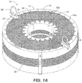
- a catalyst reactor basket 10 is shown.
- the basket is generally cylindrical in shape and has a generally circular aperture 12 that extends axially through the basket.
- a cover 14 is provided at the top end of the basket.
- a cover is also provided at the bottom end the basket.
- the cover includes an outer rim 16 and an inner rim 18.
- the rims 16, 18 extend around the periphery of the covers and provide structural rigidity to the cover.
- the rims can include relief cuts 16a and 18a in order to aid in forming the rims into circular rings.
- the relief cuts can vary in size and shape.
- a mesh 20 extends between the rims 16 and 18.
- the mesh 20 is sized and shaped to provide holes that allow fluid to pass through the mesh during use of the catalyst basket while also preventing catalyst particles from passing through the mesh. As such, the catalyst particles are retained within the basket.
- the mesh 20 can be attached the rims 16 and 18 by, for example, welding the mesh to the rims such as by spot welding. Other suitable attachments are possible.
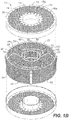
- the basket 10 includes a support frame 22.
- the support frame 22 can be arranged in layers such that the basket 10 includes an upper support frame layer 24 and a lower support frame layer 26.
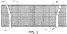
- an intermediate support frame layer 25 (See Fig. 2 ) that is disposed between the upper and lower support frame layers can be included.
- Each support frame layer includes an outer ring 28 and an inner ring 30.
- the support frame 22 can include vertical supports 32 that can extend between the rings of the different layers of the support frame.
- the support frame can also include radial supports 34 that extend between the outer and inner rings of a respective layer. As shown in Fig. 1B , for example, four vertical supports 32 extend between the outer ring 28 of the upper layer and the outer ring of the intermediate layer.
- each vertical supports 32 extend between the inner ring 30 of the upper layer and the inner ring of the intermediate layer.
- the vertical supports that connect the inner rings and the outer rings of the upper and intermediate layers are preferably the same length such that the upper and intermediate layers are maintained in generally parallel planes.
- vertical supports connect the outer and inner rings of the intermediate layer and the bottom layer.
- radial supports 34 extend between the outer ring 28 and the inner ring 30 of the intermediate layer.
- the arrangement shown in Fig. 1B is structured such that radial supports are not required in the upper and lower layers, but they can optionally be included.
- the support frame elements e.g., inner rings, outer rings, vertical supports and radial supports
- the support frame elements can be connected using suitable fasteners and/or fastening methods, such as welding, for example.
- the outer wall 36 of the basket 10 is supported by the outer rings 28 of each of the layers of the support frame.
- the outer wall 36 of the basket extends cylindrically around the basket to define the outer circumferential periphery thereof. Accordingly, the outer wall defines the outer limit of the cylindrical volume of the catalyst basket.
- the inner wall 38 of the basket is supported by the inner rings 28 of each of the layers of the support frame.
- the inner wall 38 of the basket extends cylindrically to define the inner boundary of the cylindrical volume of the catalyst basket.
- the inner wall 38 of the basket extends also defines the circumferential periphery of the aperture 12.
- the outer wall 36 is preferably permeable such that liquids can flow through the outer wall so that fluid can be exchanged between the interior and exterior of the basket.
- the inner wall 38 is preferably permeable such that liquids can flow through the inner wall so that fluid can be exchanged between the interior and exterior of the basket.
- the outer and inner walls can be made from a mesh material, such as a woven steel mesh.
- the outer, inner and dividing walls, or at least a portion thereof can alternatively be made from non-permeable steel plate to prevent liquid entering and exiting the basket.
- the liquid flow is axial therefore no flow is expected to flow through the outer and inner walls and, therefore, surfaces, or at least portions thereof, that are parallel to the axial flow direction can be non-permeable.
- the mesh can be steel wire cloth, woven, 14 x 14 mesh with a .020 inch wire diameter.
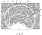
- the wire mesh of the inner and outer walls can be secured to the support frame member using wire 39.
- Other suitable attachment means and methods are also contemplated.
- a dividing wall 40 can extend between the outer ring 28 and the inner ring 30 and can be secured to the intermediate layer 25. As can be seen in Figs. 1B and 2 , the dividing wall 40 divides the interior of the basket into first and second chambers 42 and 44, respectively.
- the dividing wall 40 is fluid permeable so that fluid can flow through the dividing wall in an axial direction along the length (height) of the basket.
- the dividing wall can be made of the same woven mesh as the inner and outer walls.
- partitions 46 can extend radially between the inner and outer rings of the support frames. As shown in Fig. 1B , four partitions 46 are provided in each of the upper and lower chambers, for example.
- the partitions 46 define compartments 48 in the upper and lower chambers.
- the compartments 48 can receive materials such as catalyst material.
- the partitions 46 are preferably not fluid permeable so that effect of material in one compartment can be more readily isolated from the material in an adjacent compartment.
- the partitions can be solid steel sheet material.
- the partitions can define four compartments in each of the upper and lower chambers, respectively, for example. Partitions can be added or removed to increase or decrease the number of compartments. Accordingly, the partitions 46 and the dividing wall 40 define the interior of the basket such that the basket has an upper chamber with four compartments and a lower chamber with four compartments, as illustrated.
- the partitions in the upper and lower chambers are aligned so that a compartment in the lower chamber is aligned with a corresponding compartment in the upper chamber and are sized and shaped to be coextensive, without overlap.
- the partitions in the upper and lower chambers can be arranged such that a compartment in one chamber is sized, shaped, and positioned such that there is overlap between compartments along the axial direction.
- each chamber includes multiple compartments allows for testing several different catalysts at the same time.
- dividing the basket into an upper chamber and a lower chamber allows for two-stage reactions in a single pass of the fluid in the axial direction along the basket.
- a first catalyst is provided in one compartment of one chamber.
- a second catalyst is provided in a second, corresponding compartment in the other chamber (i.e., the second compartment is axially aligned with the first compartment) a second catalyst is provided.
- fluid can pass through two layers of catalyst having differing properties.
- the liquid can pass through the first compartment and come into contact with the catalyst contained therein.
- the catalyst in the first compartment can be one that hydrotreats the fluid by removing sulfur and hydrogen from the fluid.
- the second compartment can include a different catalyst that can be used for cracking or further hydrogenation of the liquid as it comes into contact with the catalyst contained in the compartment. Two-stage reactions can thus be achieved with the catalyst basket of the present invention.
- the design is made to simulate a once-thru hydrocracking unit with two reactors in series of a single pass of the fluid through the basket.
- adjacent compartments can contain different catalyst materials so that different catalyst combinations can be tested simultaneously using the same reactor basket.
- the two layer, multi-compartment design of the catalyst basket allows different combinations of catalysts to be tested using the same basket.
- two different compartments in the first layer can contain catalysts A1 and A2.
- two different compartments in the second layer can contain catalysts B1 and B2. Accordingly, as the fluid passes through the reactor basket, the fluid is exposed to different combinations of catalysts.
- one fluid flow path through the basket can first expose the fluid to the catalyst A1 contained in one compartment in the first layer of the basket. After the fluid is exposed to the catalyst A1, it passes into the second layer of the basket whereupon it is exposed to the second catalyst B1 contained in a compartment in the second layer of the basket.
- the fluid can progress through another flow path in which the fluid is exposed to catalyst A2 in another compartment in the first layer of the basket and then is exposed to catalyst B2 in another compartment in the second layer of the basket.
- the fluid flowing through the reactor basket and be exposed to a combination of catalysts A1 and B1 and, using the same catalyst basket in the same reactor, the fluid simultaneously can be exposed to the combination of catalysts A2 and B2. Accordingly, multiple combinations of catalysts can be tested in the same chamber using the same basket simultaneously.
- the basket design allows for efficient and effective testing of many catalysts and combinations so that more suitable and effective catalysts can be identified and employed in future reactions.
- the covers 14 can be removed from the top and bottom ends of the basket to allow for filling the compartments with catalyst material.
- Clips can be provided on the sides of the basket for selectively attaching the covers to the ends of the basket. For example, the clips can be detached from a first cover and the cover can be removed to expose the compartments in the first chamber. Various catalyst materials can be added to the exposed compartments and the cover can be re-secured using the clips. Then the basket can be flipped so that the second cover at the other end of the basket can be removed to expose the compartment of the second chamber. Various catalyst materials can be added to the exposed compartments of the second chamber and the second cover can be re-secured using the clips. Accordingly, the two-layer, multi-compartment catalyst reactor basket can be loaded with catalyst.
- Hooks 50 can optionally be connected to the frame of the basket.
- the hooks can support the basket and couple the basket to the internals of the reactor.
- the hooks can also be used to support the basket during loading and unloading of the catalyst at the end of the reactor cycle.
- the catalysts are usually vacuumed at the end of the cycle. By hanging the basket, the basket will be untacked during the catalyst vacuuming.
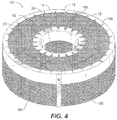
- Fig. 4 illustrates a catalyst basket having a single layer with four chambers.
- the four chamber can contain catalyst that allows axial flow through in a similar manner as described above.
Landscapes
- Chemical & Material Sciences (AREA)
- Chemical Kinetics & Catalysis (AREA)
- Organic Chemistry (AREA)
- Oil, Petroleum & Natural Gas (AREA)
- Engineering & Computer Science (AREA)
- General Chemical & Material Sciences (AREA)
- Physics & Mathematics (AREA)
- Fluid Mechanics (AREA)
- Devices And Processes Conducted In The Presence Of Fluids And Solid Particles (AREA)
- Physical Or Chemical Processes And Apparatus (AREA)
Abstract
Description
- The present invention relates to catalyst reactor baskets.
- Catalyst reactor systems having differing designs are known in various documents, including, among others,
U.S. Design Patent No. D257,281 entitled "Fossil Fuel Catalyst Generator" andU.S. Pat. Pub. No. 2004/0018124 entitled "Comprises cylindrical basket suitable for containing predetermined amount of catalyst; improved materials handling." The specific designs and features of the catalyst baskets described in these documents can best be appreciated by a review of their respective disclosures. -
-
Fig. 1A is a top perspective view of the catalyst reactor basket with a cover attached according to an embodiment of the invention. -
Fig. 1B is an exploded, top perspective view of the catalyst reactor basket; -
Fig. 2 is a side perspective view of the catalyst reactor basket with the cover removed; -
Fig. 3 is a top perspective view close up of the aperture of the catalyst basket; and -
Fig. 4 is a top perspective view of the catalyst reactor basket according to another aspect of the invention. - According to an aspect of the present invention, a catalyst reactor basket is provided. The catalyst basket includes an outer side wall extending along the outer circumferential periphery of the basket and extending in an axial direction to define a generally cylindrical inner volume of the basket. At least a portion of the outer side wall is fluid permeable. The catalyst basket includes an inner side wall disposed within the outer side wall. The inner side wall extends circumferential and axially to define an aperture that defines a inner boundary of the volume of the basket. The aperture is sized and shaped to allow a fluid to flow axially with respect to the basket. At least a portion of the inner side wall is fluid permeable. First and second covers are disposed on opposite ends of the outer side wall and inner side wall. The first and second covers define respective ends of the inner volume of the basket, at least a portion of the first and second covers being fluid permeable. A dividing wall is disposed between the first and second covers. The dividing wall defines a first and second chamber within the inner volume of the basket. At least a portion of the dividing wall is fluid permeable. A plurality of partitions are disposed within the first and second chambers. Each partition extends radially between the outer side wall and the inner side wall and extends axially between the dividing wall and a respective cover. The plurality of partitions define a plurality of compartments within the first and second chambers, each compartment being sized and shaped to receive a catalyst.
- In accordance with a further aspect, a first compartment in the first chamber is aligned with a second compartment in the second chamber along an axis of the basket such that any fluid can flow through the first compartment and subsequently flow through the second compartment.
- In accordance with yet a further aspect, the first compartment is sized to receive a first catalyst and the second compartment is sized to receive a second catalyst such that the fluid first contacts the first catalyst and subsequently contacts a second catalyst along an axial flow path of the fluid.
- In accordance with a yet further aspect, the first catalyst has properties that are different from the second catalyst.
- In accordance with a further aspect, the partitions provide a fluid barrier between adjacent compartments.
- In accordance with a further aspect, at least one compartment is sized to receive a first catalyst that has different properties than a second catalyst in an adjacent compartment.
- In accordance with a further aspect, the catalyst basket includes a support frame wherein the outer wall, inner wall, and dividing wall are supported by the frame.
- In accordance with a yet further aspect, the catalyst reactor basket includes clips that removablely secure the covers to respective ends of the basket.
- In accordance with a further aspect, hooks are coupled to the basket, the hooks being sized and shaped to support the basket such that the basket hangs from the hooks.
- In accordance with a further aspect, at least a portion of the inner side wall is fluid permeable.
- In accordance with a further aspect, at least a portion of the outer wall is fluid permeable.
- Referring to
Figs 1A and1B , acatalyst reactor basket 10 is shown. The basket is generally cylindrical in shape and has a generallycircular aperture 12 that extends axially through the basket. Acover 14 is provided at the top end of the basket. A cover is also provided at the bottom end the basket. The cover includes anouter rim 16 and aninner rim 18. Therims relief cuts 16a and 18a in order to aid in forming the rims into circular rings. The relief cuts can vary in size and shape. Amesh 20 extends between therims mesh 20 is sized and shaped to provide holes that allow fluid to pass through the mesh during use of the catalyst basket while also preventing catalyst particles from passing through the mesh. As such, the catalyst particles are retained within the basket. Themesh 20 can be attached therims - Referring to
Figs. 1B and3 , thebasket 10 includes asupport frame 22. Thesupport frame 22 can be arranged in layers such that thebasket 10 includes an uppersupport frame layer 24 and a lowersupport frame layer 26. In addition, an intermediate support frame layer 25 (SeeFig. 2 ) that is disposed between the upper and lower support frame layers can be included. Each support frame layer includes anouter ring 28 and aninner ring 30. Thesupport frame 22 can includevertical supports 32 that can extend between the rings of the different layers of the support frame. The support frame can also includeradial supports 34 that extend between the outer and inner rings of a respective layer. As shown inFig. 1B , for example, four vertical supports 32 extend between theouter ring 28 of the upper layer and the outer ring of the intermediate layer. Similarly, fourvertical supports 32 extend between theinner ring 30 of the upper layer and the inner ring of the intermediate layer. The vertical supports that connect the inner rings and the outer rings of the upper and intermediate layers are preferably the same length such that the upper and intermediate layers are maintained in generally parallel planes. In a similar arrangement, vertical supports connect the outer and inner rings of the intermediate layer and the bottom layer. In addition, as noted, radial supports 34 extend between theouter ring 28 and theinner ring 30 of the intermediate layer. The arrangement shown inFig. 1B is structured such that radial supports are not required in the upper and lower layers, but they can optionally be included. The support frame elements (e.g., inner rings, outer rings, vertical supports and radial supports) can be metal, such as tubular metal, for example. The support frame elements can be connected using suitable fasteners and/or fastening methods, such as welding, for example. - The
outer wall 36 of thebasket 10 is supported by theouter rings 28 of each of the layers of the support frame. Theouter wall 36 of the basket extends cylindrically around the basket to define the outer circumferential periphery thereof. Accordingly, the outer wall defines the outer limit of the cylindrical volume of the catalyst basket. Theinner wall 38 of the basket is supported by theinner rings 28 of each of the layers of the support frame. Theinner wall 38 of the basket extends cylindrically to define the inner boundary of the cylindrical volume of the catalyst basket. Theinner wall 38 of the basket extends also defines the circumferential periphery of theaperture 12. Theouter wall 36 is preferably permeable such that liquids can flow through the outer wall so that fluid can be exchanged between the interior and exterior of the basket. Similarly, theinner wall 38 is preferably permeable such that liquids can flow through the inner wall so that fluid can be exchanged between the interior and exterior of the basket. The outer and inner walls can be made from a mesh material, such as a woven steel mesh. Optionally, the outer, inner and dividing walls, or at least a portion thereof, can alternatively be made from non-permeable steel plate to prevent liquid entering and exiting the basket. In certain down flow reactors, the liquid flow is axial therefore no flow is expected to flow through the outer and inner walls and, therefore, surfaces, or at least portions thereof, that are parallel to the axial flow direction can be non-permeable. In some embodiments, for example, the mesh can be steel wire cloth, woven, 14 x 14 mesh with a .020 inch wire diameter. As can be seen inFig. 3 , for example, the wire mesh of the inner and outer walls can be secured to the support framemember using wire 39. Other suitable attachment means and methods are also contemplated. - A dividing
wall 40 can extend between theouter ring 28 and theinner ring 30 and can be secured to the intermediate layer 25. As can be seen inFigs. 1B and2 , the dividingwall 40 divides the interior of the basket into first andsecond chambers wall 40 is fluid permeable so that fluid can flow through the dividing wall in an axial direction along the length (height) of the basket. For example, the dividing wall can be made of the same woven mesh as the inner and outer walls. In addition,partitions 46 can extend radially between the inner and outer rings of the support frames. As shown inFig. 1B , fourpartitions 46 are provided in each of the upper and lower chambers, for example. Thepartitions 46 definecompartments 48 in the upper and lower chambers. Thecompartments 48 can receive materials such as catalyst material. Thepartitions 46 are preferably not fluid permeable so that effect of material in one compartment can be more readily isolated from the material in an adjacent compartment. For example, the partitions can be solid steel sheet material. - As shown in
Fig. 1B , the partitions can define four compartments in each of the upper and lower chambers, respectively, for example. Partitions can be added or removed to increase or decrease the number of compartments. Accordingly, thepartitions 46 and the dividingwall 40 define the interior of the basket such that the basket has an upper chamber with four compartments and a lower chamber with four compartments, as illustrated. Preferably, the partitions in the upper and lower chambers are aligned so that a compartment in the lower chamber is aligned with a corresponding compartment in the upper chamber and are sized and shaped to be coextensive, without overlap. Alternatively, the partitions in the upper and lower chambers can be arranged such that a compartment in one chamber is sized, shaped, and positioned such that there is overlap between compartments along the axial direction. - The structural arrangement of basket in which each chamber includes multiple compartments allows for testing several different catalysts at the same time. In addition, dividing the basket into an upper chamber and a lower chamber allows for two-stage reactions in a single pass of the fluid in the axial direction along the basket. For example, in one compartment of one chamber a first catalyst is provided. In a second, corresponding compartment in the other chamber (i.e., the second compartment is axially aligned with the first compartment) a second catalyst is provided. Accordingly, fluid can pass through two layers of catalyst having differing properties. For example, the liquid can pass through the first compartment and come into contact with the catalyst contained therein. The catalyst in the first compartment can be one that hydrotreats the fluid by removing sulfur and hydrogen from the fluid. As the fluid travels along the axial direction of the basket the fluid enters the second compartment in the next chamber of the basket. The second compartment can include a different catalyst that can be used for cracking or further hydrogenation of the liquid as it comes into contact with the catalyst contained in the compartment. Two-stage reactions can thus be achieved with the catalyst basket of the present invention. The design is made to simulate a once-thru hydrocracking unit with two reactors in series of a single pass of the fluid through the basket. In addition, adjacent compartments can contain different catalyst materials so that different catalyst combinations can be tested simultaneously using the same reactor basket.
- The two layer, multi-compartment design of the catalyst basket allows different combinations of catalysts to be tested using the same basket. For example, two different compartments in the first layer can contain catalysts A1 and A2. In addition, two different compartments in the second layer can contain catalysts B1 and B2. Accordingly, as the fluid passes through the reactor basket, the fluid is exposed to different combinations of catalysts. For example, one fluid flow path through the basket can first expose the fluid to the catalyst A1 contained in one compartment in the first layer of the basket. After the fluid is exposed to the catalyst A1, it passes into the second layer of the basket whereupon it is exposed to the second catalyst B1 contained in a compartment in the second layer of the basket. Similarly, the fluid can progress through another flow path in which the fluid is exposed to catalyst A2 in another compartment in the first layer of the basket and then is exposed to catalyst B2 in another compartment in the second layer of the basket. As such, the fluid flowing through the reactor basket and be exposed to a combination of catalysts A1 and B1 and, using the same catalyst basket in the same reactor, the fluid simultaneously can be exposed to the combination of catalysts A2 and B2. Accordingly, multiple combinations of catalysts can be tested in the same chamber using the same basket simultaneously. As such, the basket design allows for efficient and effective testing of many catalysts and combinations so that more suitable and effective catalysts can be identified and employed in future reactions.
- The
covers 14 can be removed from the top and bottom ends of the basket to allow for filling the compartments with catalyst material. Clips can be provided on the sides of the basket for selectively attaching the covers to the ends of the basket. For example, the clips can be detached from a first cover and the cover can be removed to expose the compartments in the first chamber. Various catalyst materials can be added to the exposed compartments and the cover can be re-secured using the clips. Then the basket can be flipped so that the second cover at the other end of the basket can be removed to expose the compartment of the second chamber. Various catalyst materials can be added to the exposed compartments of the second chamber and the second cover can be re-secured using the clips. Accordingly, the two-layer, multi-compartment catalyst reactor basket can be loaded with catalyst. Hooks 50 (SeeFig. 1 ) can optionally be connected to the frame of the basket. The hooks can support the basket and couple the basket to the internals of the reactor. The hooks can also be used to support the basket during loading and unloading of the catalyst at the end of the reactor cycle. The catalysts are usually vacuumed at the end of the cycle. By hanging the basket, the basket will be untacked during the catalyst vacuuming. -
Fig. 4 illustrates a catalyst basket having a single layer with four chambers. The four chamber can contain catalyst that allows axial flow through in a similar manner as described above. - The subject matter described above is provided by way of illustration only and should not be construed as limiting. Various modifications and changes can be made to the subject matter described herein without following the example embodiments and applications illustrated and described, and without departing from the true spirit and scope of the present invention, which is set forth in the following claims.
Claims (20)
- A catalyst reactor basket arranged to receive a combination of catalysts in separate chambers, comprising:an outer side wall extending along the outer periphery of the basket and extending to define an inner volume of the basket;an inner side wall disposed within the outer side wall, the inner side wall extending to define an aperture that defines a inner boundary of the volume of the basket, the aperture being sized and shaped to allow a fluid to flow axially with respect to the basket;first and second covers disposed on opposite ends of the outer side wall and inner side wall, the first and second covers defining respective ends of the inner volume of the basket, at least a portion of the first and second covers being fluid permeable; anda dividing wall disposed between the first and second covers, the dividing wall defining a first and second chamber within the inner volume of the basket, at least a portion of the dividing wall being fluid permeable, wherein each of the first and second chambers being sized to receive a respective catalyst so as to enable a two-stage reaction in a single pass of the fluid in the axial direction.
- The catalyst reactor basket as in claim 1, further comprising a plurality of partitions disposed within the first and second chambers, each partition extending between the outer side wall and the inner side wall and between the dividing wall and a respective cover, the plurality of partitions defining a plurality of compartments within the first and second chambers, each compartment being sized and shaped to receive a catalyst.
- The catalyst reactor basket as in claim 2, wherein a first compartment in the first chamber is aligned with a second compartment in the second chamber along an axis of the basket such that any fluid can flow through the first compartment and subsequently flow through the second compartment.
- The catalyst reactor basket as in claim 3, wherein first compartment is sized to receive a first catalyst and the second compartment is sized to receive a second catalyst such that the fluid first contacts the first catalyst and subsequently contacts a second catalyst along an axial flow path of the fluid.
- The catalyst reactor basket as in claim 4, wherein the first catalyst has properties that are different from the second catalyst.
- The catalyst reactor basket as in claim 2, wherein the partitions provide a fluid barrier between adjacent compartments.
- The catalyst reactor basket as in claim 2, wherein at least one compartment is sized to receive a first catalyst that has different properties than a second catalyst in an adjacent compartment.
- The catalyst reactor basket as in claim 1, further comprising a support frame wherein the outer wall, inner wall, and dividing wall are supported by the frame.
- The catalyst reactor basket as in claim 1, further comprising clips that removably secure the covers to respective ends of the basket.
- The catalyst reactor basket as in claim 1, further comprising hooks coupled to the basket, the hooks being sized and shaped to support the basket such that the basket hangs from the hooks.
- The catalyst reactor basket as in claim 1, wherein at least a portion of the inner side wall is fluid permeable.
- The catalyst reactor basket as in claim 1, wherein at least a portion of the outer wall is fluid permeable.
- A method of catalyzing a fluid, the method comprising:disposing a catalyst reactor basket in a reactor, the basket defining a volume and having a fluid permeable dividing wall within the volume of the basket;receiving a first catalyst within a first chamber on a first side of the fluid permeable dividing wall and a second catalyst within a second chamber on a second side of the fluid permeable dividing wall; andflowing the fluid in the reactor through the first and second chambers of the catalyst reactor basket and across the fluid permeable dividing wall.
- The method of claim 13, wherein the first chamber is aligned with the second chamber along an axis of the basket, the method further comprising flowing the fluid through the first chamber and subsequently through the second chamber along the axis of the basket.
- The method of claim 14, wherein the flowing step comprises contacting the fluid with the first catalyst in the first chamber and subsequently contacting the fluid with the second catalyst in the second chamber.
- The method of claim 13, further comprising:partitioning at least one of the first and second chambers into a plurality of partitions which define a respective plurality of compartments,wherein the receiving step comprises loading a catalyst into each partition.
- The method of claim 16:wherein the fluid flows in an axial direction,wherein the partitions in the first chamber are aligned with the partitions in the second chamber such that the compartments in the first chamber are aligned with the compartments in the second chamber in the axial direction, andwherein the partitions are not fluid permeable,
the flowing step further comprising flowing the fluid through the compartments in the first chamber and subsequently flowing the fluid through the compartments in the second chamber along the axial direction. - The method of claim 13, wherein each catalyst in the first chamber is different from each catalyst in the second chamber, the flowing step further comprising flowing the fluid through the first chamber and subsequently flowing the fluid through the second chamber, the fluid contacting different combinations of catalysts in respective aligned compartments as it flows axially from the first chamber to the second chamber.
- The method of claim 13, wherein the catalyst reactor basket further comprises first and second covers spaced from the fluid impermeable dividing wall, first clips to removably secure the first cover and second clips to removably secure the second cover, the method comprising, prior to the step of disposing the catalyst reactor basket in the reactor:loading the first catalyst within the first chamber;placing the first cover on the catalyst reactor basket;securing the first cover with the first clips;flipping the basket over;loading the second catalyst within the second chamber;placing the second cover on the catalyst reactor basket; andsecuring the second cover with the second clips.
- The method of claim 13, wherein the catalyst reactor basket has hooks coupled to the basket, the method further comprising using the hooks to couple the basket to the reactor.
Applications Claiming Priority (3)
| Application Number | Priority Date | Filing Date | Title |
|---|---|---|---|
| US14/714,798 US9463427B1 (en) | 2015-05-18 | 2015-05-18 | Catalyst reactor basket |
| EP16730931.9A EP3297754B1 (en) | 2015-05-18 | 2016-05-12 | Catalyst reactor basket |
| PCT/US2016/031987 WO2016186941A1 (en) | 2015-05-18 | 2016-05-12 | Catalyst reactor basket |
Related Parent Applications (2)
| Application Number | Title | Priority Date | Filing Date |
|---|---|---|---|
| EP16730931.9A Division EP3297754B1 (en) | 2015-05-18 | 2016-05-12 | Catalyst reactor basket |
| EP16730931.9A Division-Into EP3297754B1 (en) | 2015-05-18 | 2016-05-12 | Catalyst reactor basket |
Publications (1)
| Publication Number | Publication Date |
|---|---|
| EP3501634A1 true EP3501634A1 (en) | 2019-06-26 |
Family
ID=56148649
Family Applications (2)
| Application Number | Title | Priority Date | Filing Date |
|---|---|---|---|
| EP16730931.9A Not-in-force EP3297754B1 (en) | 2015-05-18 | 2016-05-12 | Catalyst reactor basket |
| EP19155981.4A Withdrawn EP3501634A1 (en) | 2015-05-18 | 2016-05-12 | Catalyst reactor basket |
Family Applications Before (1)
| Application Number | Title | Priority Date | Filing Date |
|---|---|---|---|
| EP16730931.9A Not-in-force EP3297754B1 (en) | 2015-05-18 | 2016-05-12 | Catalyst reactor basket |
Country Status (8)
| Country | Link |
|---|---|
| US (2) | US9463427B1 (en) |
| EP (2) | EP3297754B1 (en) |
| JP (1) | JP6661875B2 (en) |
| KR (1) | KR20180008618A (en) |
| CN (1) | CN107635654B (en) |
| SA (1) | SA517390232B1 (en) |
| SG (1) | SG11201708669WA (en) |
| WO (1) | WO2016186941A1 (en) |
Cited By (1)
| Publication number | Priority date | Publication date | Assignee | Title |
|---|---|---|---|---|
| WO2021213747A1 (en) * | 2020-04-20 | 2021-10-28 | Haldor Topsøe A/S | Reactor for a catalytic process |
Families Citing this family (11)
| Publication number | Priority date | Publication date | Assignee | Title |
|---|---|---|---|---|
| US9463427B1 (en) * | 2015-05-18 | 2016-10-11 | Saudi Arabian Oil Company | Catalyst reactor basket |
| SE540903C2 (en) | 2017-03-06 | 2018-12-18 | Spinchem Ab | Flow-promoting device, a reactor arrangement and the use of such flow-promoting device |
| USD847371S1 (en) * | 2017-08-23 | 2019-04-30 | Saudi Arabian Oil Company | Tubular catalyst basket |
| FR3072305B1 (en) * | 2017-10-18 | 2022-05-06 | Ifp Energies Now | REMOVABLE BASKET FOR CATALYTIC REACTOR |
| CN109876747A (en) * | 2019-04-02 | 2019-06-14 | 吉林凯莱英医药化学有限公司 | Pillar flow reactor and pillar continuous reaction system |
| US11071959B2 (en) | 2019-11-18 | 2021-07-27 | Saudi Arabian Oil Company | Catalyst layering in commercial reactor baskets |
| US11571672B2 (en) | 2019-11-25 | 2023-02-07 | Saudi Arabian Oil Company | Method of providing catalysts for a fluidized bed reactor |
| US11260356B2 (en) | 2020-01-13 | 2022-03-01 | Saudi Arabian Oil Company | Catalyst testing process and apparatus |
| CN111569785B (en) * | 2020-03-25 | 2021-04-30 | 南京延长反应技术研究院有限公司 | Immersed propylene hydration micro-interface enhanced reaction system and process |
| US20240181414A1 (en) * | 2021-04-21 | 2024-06-06 | Chevron U.S.A Inc. | Filtration device for a down-flow hydroprocessing reactor |
| GB2637383A (en) * | 2023-11-16 | 2025-07-23 | Johnson Matthey Davy Technologies Ltd | Improvements in or relating to catalyst carriers for tubular reactors |
Citations (4)
| Publication number | Priority date | Publication date | Assignee | Title |
|---|---|---|---|---|
| US257281A (en) | 1882-05-02 | Adam boens | ||
| GB705705A (en) * | 1951-08-08 | 1954-03-17 | Gottfried Bischoff G M B H | Improvements in or relating to reaction vessels equipped with insertion baskets for containing solid material which participates in a reaction within the vessel, and to insertion baskets for such vessels |
| EP0483975A1 (en) * | 1990-10-03 | 1992-05-06 | Nagaoka International Corporation | Device and method for holding catalyst in a radial flow reactor |
| EP1300190A1 (en) * | 2001-10-04 | 2003-04-09 | Methanol Casale S.A. | Heterogeneous catalytic reactor with modular catalytic cartridge |
Family Cites Families (30)
| Publication number | Priority date | Publication date | Assignee | Title |
|---|---|---|---|---|
| US2332224A (en) * | 1941-02-25 | 1943-10-19 | Blaw Knox Co | Gas and liquid contact apparatus |
| US2419249A (en) | 1945-12-26 | 1947-04-22 | Gerald G Bridges | Clothes drying rack |
| US2596781A (en) | 1945-12-29 | 1952-05-13 | Moore Co | Fan |
| US2915127A (en) | 1956-03-29 | 1959-12-01 | Abendroth O'farrel | Fluid controlled junk basket |
| DE2559661B2 (en) * | 1975-10-01 | 1978-10-26 | Deggendorfer Werft Und Eisenbau Gmbh, 8360 Deggendorf | Reaction apparatus |
| US4052142A (en) | 1976-05-17 | 1977-10-04 | John Zink Company | Air velocity burner |
| USD257281S (en) | 1978-02-02 | 1980-10-07 | Thermics Corporation | Fossil fuel catalyst generator |
| US4225562A (en) * | 1979-05-14 | 1980-09-30 | Uop Inc. | Multi-bed catalytic reactor |
| US4323343A (en) | 1980-02-04 | 1982-04-06 | John Zink Company | Burner assembly for smokeless combustion of low calorific value gases |
| JPS5823635U (en) * | 1981-08-03 | 1983-02-15 | 三菱重工業株式会社 | Solid-gas contact reactor |
| USD278613S (en) | 1982-12-10 | 1985-04-30 | Einsel Kenneth D | Planter |
| US4662669A (en) * | 1985-09-30 | 1987-05-05 | Amoco Corporation | Spent catalyst container |
| JPS6451126A (en) * | 1987-08-20 | 1989-02-27 | Mitsubishi Heavy Ind Ltd | High temperature catalyst device |
| JPH01107844A (en) * | 1987-10-21 | 1989-04-25 | Toshiba Corp | Reformer |
| USD304230S (en) | 1987-10-21 | 1989-10-24 | Tim Wang | Ceramic heating element |
| US4799878A (en) | 1987-11-16 | 1989-01-24 | Schaeffer Thomas W | Rich fume incinerator |
| US4946478A (en) | 1989-05-15 | 1990-08-07 | Aaxon Industrial, Inc. | Particulate collection and dewatering means for airborne particulate matter |
| JPH03106434A (en) * | 1989-09-20 | 1991-05-07 | Toshiba Corp | Fuel reforming apparatus |
| JPH0685866B2 (en) * | 1991-01-25 | 1994-11-02 | 株式会社日立製作所 | Catalytic reactor |
| USD340942S (en) | 1992-02-14 | 1993-11-02 | Mobile Music, Inc. | Radial musical instrument stand spacer |
| USD343230S (en) | 1992-09-09 | 1994-01-11 | Royal Sovereign Corp. | Portable electric heater |
| USD346017S (en) | 1992-09-09 | 1994-04-12 | Royal Sovereign Corp. | Portable electric heater |
| USD341417S (en) | 1993-02-01 | 1993-11-16 | Sun Star United Corporation | Blow heater |
| EP0940172A1 (en) * | 1998-02-25 | 1999-09-08 | Ammonia Casale S.A. | Process for effecting mass transfer between a liquid phase and a gaseous phase |
| KR100286572B1 (en) * | 1998-11-19 | 2001-04-16 | 남창우 | Fuel cell vehicle small fuel reformer and its system using metal thin film |
| US7566487B2 (en) * | 2004-07-07 | 2009-07-28 | Jonathan Jay Feinstein | Reactor with primary and secondary channels |
| US7497998B2 (en) * | 2006-09-06 | 2009-03-03 | Snc-Lavalin Inc. | Gas converter |
| US20080152551A1 (en) * | 2006-12-21 | 2008-06-26 | Senetar John J | Screenless moving bed reactor |
| US8409521B2 (en) * | 2008-08-13 | 2013-04-02 | Air Products And Chemicals, Inc. | Tubular reactor with jet impingement heat transfer |
| US9463427B1 (en) * | 2015-05-18 | 2016-10-11 | Saudi Arabian Oil Company | Catalyst reactor basket |
-
2015
- 2015-05-18 US US14/714,798 patent/US9463427B1/en active Active
-
2016
- 2016-05-12 EP EP16730931.9A patent/EP3297754B1/en not_active Not-in-force
- 2016-05-12 KR KR1020177035926A patent/KR20180008618A/en not_active Ceased
- 2016-05-12 EP EP19155981.4A patent/EP3501634A1/en not_active Withdrawn
- 2016-05-12 CN CN201680028397.2A patent/CN107635654B/en not_active Expired - Fee Related
- 2016-05-12 JP JP2017558696A patent/JP6661875B2/en not_active Expired - Fee Related
- 2016-05-12 SG SG11201708669WA patent/SG11201708669WA/en unknown
- 2016-05-12 WO PCT/US2016/031987 patent/WO2016186941A1/en not_active Ceased
- 2016-10-03 US US15/284,046 patent/US9802173B2/en active Active
-
2017
- 2017-10-25 SA SA517390232A patent/SA517390232B1/en unknown
Patent Citations (5)
| Publication number | Priority date | Publication date | Assignee | Title |
|---|---|---|---|---|
| US257281A (en) | 1882-05-02 | Adam boens | ||
| GB705705A (en) * | 1951-08-08 | 1954-03-17 | Gottfried Bischoff G M B H | Improvements in or relating to reaction vessels equipped with insertion baskets for containing solid material which participates in a reaction within the vessel, and to insertion baskets for such vessels |
| EP0483975A1 (en) * | 1990-10-03 | 1992-05-06 | Nagaoka International Corporation | Device and method for holding catalyst in a radial flow reactor |
| EP1300190A1 (en) * | 2001-10-04 | 2003-04-09 | Methanol Casale S.A. | Heterogeneous catalytic reactor with modular catalytic cartridge |
| US20040018124A1 (en) | 2001-10-04 | 2004-01-29 | Ermanno Filippi | Heterogeneous catalytic reactor with a modular catalytic cartridge |
Cited By (1)
| Publication number | Priority date | Publication date | Assignee | Title |
|---|---|---|---|---|
| WO2021213747A1 (en) * | 2020-04-20 | 2021-10-28 | Haldor Topsøe A/S | Reactor for a catalytic process |
Also Published As
| Publication number | Publication date |
|---|---|
| CN107635654A (en) | 2018-01-26 |
| SA517390232B1 (en) | 2021-04-11 |
| US9463427B1 (en) | 2016-10-11 |
| US20170021320A1 (en) | 2017-01-26 |
| EP3297754A1 (en) | 2018-03-28 |
| KR20180008618A (en) | 2018-01-24 |
| US9802173B2 (en) | 2017-10-31 |
| SG11201708669WA (en) | 2017-12-28 |
| JP2018516745A (en) | 2018-06-28 |
| EP3297754B1 (en) | 2019-03-13 |
| WO2016186941A1 (en) | 2016-11-24 |
| JP6661875B2 (en) | 2020-03-11 |
| CN107635654B (en) | 2020-08-25 |
Similar Documents
| Publication | Publication Date | Title |
|---|---|---|
| US9802173B2 (en) | Catalyst reactor basket | |
| US7226568B1 (en) | Plural conduit replaceable outer support structure for radial flow system | |
| US5057468A (en) | Catalytic distillation structure | |
| JP2018516745A5 (en) | ||
| RU2746451C2 (en) | Adsorption receptacle with radial flow equipped with flexible divider | |
| US9486767B2 (en) | Multi-tube radial bed reactor | |
| RU2739068C2 (en) | Chemical reactor containing floating plate | |
| JP2015526277A (en) | Apparatus and method for holding solid material in a radial flow reactor | |
| US20140047806A1 (en) | Filter module and filter system comprising same | |
| WO2018119210A1 (en) | Radial flow adsorber vessel for gas separation | |
| US7829038B2 (en) | Segmented outer catalyst retention screen for stacked radial flow reactors | |
| EP3417932B1 (en) | Reactors with fixed or moving bed and radial flow with improved internals. | |
| FI69253C (en) | FILTER FOR EXPLORATION OF FASHION EQUIPMENT I IN VAETSKA SPCIELLT FAESTA FOERORENINGAR I REAKTORKYLVATTEN I KAERNKRA FTTATIONER | |
| US20170065955A1 (en) | Reactor for a catalytic process | |
| JP4226908B2 (en) | Media layer support grid | |
| EP3592453B1 (en) | Flow-promoting device, a reactor arrangement and the use of such flow-promoting device | |
| US11071959B2 (en) | Catalyst layering in commercial reactor baskets | |
| KR20210057180A (en) | Hydrocarbon conversion apparatus and method | |
| US20220032244A1 (en) | Flow distributor and reactor using such flow distributor | |
| JP2016145752A (en) | Radioactive substance removal equipment | |
| JP2021030160A (en) | Cartridge for multistage loading | |
| US20210154636A1 (en) | Method of catalyst testing in fluidized bed reactors using catalyst capsules | |
| US10576439B2 (en) | Scale collection device for downflow reactors | |
| RU169758U1 (en) | Radial type reactor for catalytic dehydrogenation of hydrocarbons | |
| US11298669B2 (en) | Scale collection device for downflow reactors |
Legal Events
| Date | Code | Title | Description |
|---|---|---|---|
| PUAI | Public reference made under article 153(3) epc to a published international application that has entered the european phase |
Free format text: ORIGINAL CODE: 0009012 |
|
| STAA | Information on the status of an ep patent application or granted ep patent |
Free format text: STATUS: THE APPLICATION HAS BEEN PUBLISHED |
|
| AC | Divisional application: reference to earlier application |
Ref document number: 3297754 Country of ref document: EP Kind code of ref document: P |
|
| AK | Designated contracting states |
Kind code of ref document: A1 Designated state(s): AL AT BE BG CH CY CZ DE DK EE ES FI FR GB GR HR HU IE IS IT LI LT LU LV MC MK MT NL NO PL PT RO RS SE SI SK SM TR |
|
| STAA | Information on the status of an ep patent application or granted ep patent |
Free format text: STATUS: REQUEST FOR EXAMINATION WAS MADE |
|
| 17P | Request for examination filed |
Effective date: 20191224 |
|
| RBV | Designated contracting states (corrected) |
Designated state(s): AL AT BE BG CH CY CZ DE DK EE ES FI FR GB GR HR HU IE IS IT LI LT LU LV MC MK MT NL NO PL PT RO RS SE SI SK SM TR |
|
| STAA | Information on the status of an ep patent application or granted ep patent |
Free format text: STATUS: EXAMINATION IS IN PROGRESS |
|
| 17Q | First examination report despatched |
Effective date: 20201005 |
|
| STAA | Information on the status of an ep patent application or granted ep patent |
Free format text: STATUS: THE APPLICATION IS DEEMED TO BE WITHDRAWN |
|
| 18D | Application deemed to be withdrawn |
Effective date: 20221201 |