EP1300190A1 - Heterogeneous catalytic reactor with modular catalytic cartridge - Google Patents
Heterogeneous catalytic reactor with modular catalytic cartridge Download PDFInfo
- Publication number
- EP1300190A1 EP1300190A1 EP01123804A EP01123804A EP1300190A1 EP 1300190 A1 EP1300190 A1 EP 1300190A1 EP 01123804 A EP01123804 A EP 01123804A EP 01123804 A EP01123804 A EP 01123804A EP 1300190 A1 EP1300190 A1 EP 1300190A1
- Authority
- EP
- European Patent Office
- Prior art keywords
- container
- fact
- basket
- catalytic
- partial opening
- Prior art date
- Legal status (The legal status is an assumption and is not a legal conclusion. Google has not performed a legal analysis and makes no representation as to the accuracy of the status listed.)
- Withdrawn
Links
Images


Classifications
-
- B—PERFORMING OPERATIONS; TRANSPORTING
- B01—PHYSICAL OR CHEMICAL PROCESSES OR APPARATUS IN GENERAL
- B01J—CHEMICAL OR PHYSICAL PROCESSES, e.g. CATALYSIS OR COLLOID CHEMISTRY; THEIR RELEVANT APPARATUS
- B01J8/00—Chemical or physical processes in general, conducted in the presence of fluids and solid particles; Apparatus for such processes
- B01J8/02—Chemical or physical processes in general, conducted in the presence of fluids and solid particles; Apparatus for such processes with stationary particles, e.g. in fixed beds
- B01J8/04—Chemical or physical processes in general, conducted in the presence of fluids and solid particles; Apparatus for such processes with stationary particles, e.g. in fixed beds the fluid passing successively through two or more beds
- B01J8/0446—Chemical or physical processes in general, conducted in the presence of fluids and solid particles; Apparatus for such processes with stationary particles, e.g. in fixed beds the fluid passing successively through two or more beds the flow within the beds being predominantly vertical
- B01J8/0461—Chemical or physical processes in general, conducted in the presence of fluids and solid particles; Apparatus for such processes with stationary particles, e.g. in fixed beds the fluid passing successively through two or more beds the flow within the beds being predominantly vertical in two or more cylindrical annular shaped beds
- B01J8/0469—Chemical or physical processes in general, conducted in the presence of fluids and solid particles; Apparatus for such processes with stationary particles, e.g. in fixed beds the fluid passing successively through two or more beds the flow within the beds being predominantly vertical in two or more cylindrical annular shaped beds the beds being superimposed one above the other
-
- B—PERFORMING OPERATIONS; TRANSPORTING
- B01—PHYSICAL OR CHEMICAL PROCESSES OR APPARATUS IN GENERAL
- B01J—CHEMICAL OR PHYSICAL PROCESSES, e.g. CATALYSIS OR COLLOID CHEMISTRY; THEIR RELEVANT APPARATUS
- B01J19/00—Chemical, physical or physico-chemical processes in general; Their relevant apparatus
- B01J19/24—Stationary reactors without moving elements inside
- B01J19/248—Reactors comprising multiple separated flow channels
- B01J19/249—Plate-type reactors
-
- B—PERFORMING OPERATIONS; TRANSPORTING
- B01—PHYSICAL OR CHEMICAL PROCESSES OR APPARATUS IN GENERAL
- B01J—CHEMICAL OR PHYSICAL PROCESSES, e.g. CATALYSIS OR COLLOID CHEMISTRY; THEIR RELEVANT APPARATUS
- B01J8/00—Chemical or physical processes in general, conducted in the presence of fluids and solid particles; Apparatus for such processes
- B01J8/0015—Feeding of the particles in the reactor; Evacuation of the particles out of the reactor
- B01J8/0035—Periodical feeding or evacuation
-
- B—PERFORMING OPERATIONS; TRANSPORTING
- B01—PHYSICAL OR CHEMICAL PROCESSES OR APPARATUS IN GENERAL
- B01J—CHEMICAL OR PHYSICAL PROCESSES, e.g. CATALYSIS OR COLLOID CHEMISTRY; THEIR RELEVANT APPARATUS
- B01J8/00—Chemical or physical processes in general, conducted in the presence of fluids and solid particles; Apparatus for such processes
- B01J8/02—Chemical or physical processes in general, conducted in the presence of fluids and solid particles; Apparatus for such processes with stationary particles, e.g. in fixed beds
- B01J8/0207—Chemical or physical processes in general, conducted in the presence of fluids and solid particles; Apparatus for such processes with stationary particles, e.g. in fixed beds the fluid flow within the bed being predominantly horizontal
- B01J8/0214—Chemical or physical processes in general, conducted in the presence of fluids and solid particles; Apparatus for such processes with stationary particles, e.g. in fixed beds the fluid flow within the bed being predominantly horizontal in a cylindrical annular shaped bed
-
- B—PERFORMING OPERATIONS; TRANSPORTING
- B01—PHYSICAL OR CHEMICAL PROCESSES OR APPARATUS IN GENERAL
- B01J—CHEMICAL OR PHYSICAL PROCESSES, e.g. CATALYSIS OR COLLOID CHEMISTRY; THEIR RELEVANT APPARATUS
- B01J8/00—Chemical or physical processes in general, conducted in the presence of fluids and solid particles; Apparatus for such processes
- B01J8/02—Chemical or physical processes in general, conducted in the presence of fluids and solid particles; Apparatus for such processes with stationary particles, e.g. in fixed beds
- B01J8/0242—Chemical or physical processes in general, conducted in the presence of fluids and solid particles; Apparatus for such processes with stationary particles, e.g. in fixed beds the fluid flow within the bed being predominantly vertical
- B01J8/025—Chemical or physical processes in general, conducted in the presence of fluids and solid particles; Apparatus for such processes with stationary particles, e.g. in fixed beds the fluid flow within the bed being predominantly vertical in a cylindrical shaped bed
-
- B—PERFORMING OPERATIONS; TRANSPORTING
- B01—PHYSICAL OR CHEMICAL PROCESSES OR APPARATUS IN GENERAL
- B01J—CHEMICAL OR PHYSICAL PROCESSES, e.g. CATALYSIS OR COLLOID CHEMISTRY; THEIR RELEVANT APPARATUS
- B01J8/00—Chemical or physical processes in general, conducted in the presence of fluids and solid particles; Apparatus for such processes
- B01J8/02—Chemical or physical processes in general, conducted in the presence of fluids and solid particles; Apparatus for such processes with stationary particles, e.g. in fixed beds
- B01J8/0285—Heating or cooling the reactor
-
- B—PERFORMING OPERATIONS; TRANSPORTING
- B01—PHYSICAL OR CHEMICAL PROCESSES OR APPARATUS IN GENERAL
- B01J—CHEMICAL OR PHYSICAL PROCESSES, e.g. CATALYSIS OR COLLOID CHEMISTRY; THEIR RELEVANT APPARATUS
- B01J2208/00—Processes carried out in the presence of solid particles; Reactors therefor
- B01J2208/00008—Controlling the process
- B01J2208/00017—Controlling the temperature
- B01J2208/00026—Controlling or regulating the heat exchange system
- B01J2208/00035—Controlling or regulating the heat exchange system involving measured parameters
- B01J2208/00044—Temperature measurement
-
- B—PERFORMING OPERATIONS; TRANSPORTING
- B01—PHYSICAL OR CHEMICAL PROCESSES OR APPARATUS IN GENERAL
- B01J—CHEMICAL OR PHYSICAL PROCESSES, e.g. CATALYSIS OR COLLOID CHEMISTRY; THEIR RELEVANT APPARATUS
- B01J2208/00—Processes carried out in the presence of solid particles; Reactors therefor
- B01J2208/00008—Controlling the process
- B01J2208/00017—Controlling the temperature
- B01J2208/00106—Controlling the temperature by indirect heat exchange
- B01J2208/00168—Controlling the temperature by indirect heat exchange with heat exchange elements outside the bed of solid particles
-
- B—PERFORMING OPERATIONS; TRANSPORTING
- B01—PHYSICAL OR CHEMICAL PROCESSES OR APPARATUS IN GENERAL
- B01J—CHEMICAL OR PHYSICAL PROCESSES, e.g. CATALYSIS OR COLLOID CHEMISTRY; THEIR RELEVANT APPARATUS
- B01J2208/00—Processes carried out in the presence of solid particles; Reactors therefor
- B01J2208/00796—Details of the reactor or of the particulate material
- B01J2208/00805—Details of the particulate material
- B01J2208/00814—Details of the particulate material the particulate material being provides in prefilled containers
-
- B—PERFORMING OPERATIONS; TRANSPORTING
- B01—PHYSICAL OR CHEMICAL PROCESSES OR APPARATUS IN GENERAL
- B01J—CHEMICAL OR PHYSICAL PROCESSES, e.g. CATALYSIS OR COLLOID CHEMISTRY; THEIR RELEVANT APPARATUS
- B01J2208/00—Processes carried out in the presence of solid particles; Reactors therefor
- B01J2208/00796—Details of the reactor or of the particulate material
- B01J2208/00884—Means for supporting the bed of particles, e.g. grids, bars, perforated plates
-
- B—PERFORMING OPERATIONS; TRANSPORTING
- B01—PHYSICAL OR CHEMICAL PROCESSES OR APPARATUS IN GENERAL
- B01J—CHEMICAL OR PHYSICAL PROCESSES, e.g. CATALYSIS OR COLLOID CHEMISTRY; THEIR RELEVANT APPARATUS
- B01J2219/00—Chemical, physical or physico-chemical processes in general; Their relevant apparatus
- B01J2219/24—Stationary reactors without moving elements inside
- B01J2219/2401—Reactors comprising multiple separate flow channels
- B01J2219/245—Plate-type reactors
- B01J2219/2451—Geometry of the reactor
- B01J2219/2455—Plates arranged radially
-
- B—PERFORMING OPERATIONS; TRANSPORTING
- B01—PHYSICAL OR CHEMICAL PROCESSES OR APPARATUS IN GENERAL
- B01J—CHEMICAL OR PHYSICAL PROCESSES, e.g. CATALYSIS OR COLLOID CHEMISTRY; THEIR RELEVANT APPARATUS
- B01J2219/00—Chemical, physical or physico-chemical processes in general; Their relevant apparatus
- B01J2219/24—Stationary reactors without moving elements inside
- B01J2219/2401—Reactors comprising multiple separate flow channels
- B01J2219/245—Plate-type reactors
- B01J2219/2451—Geometry of the reactor
- B01J2219/2456—Geometry of the plates
- B01J2219/2458—Flat plates, i.e. plates which are not corrugated or otherwise structured, e.g. plates with cylindrical shape
-
- B—PERFORMING OPERATIONS; TRANSPORTING
- B01—PHYSICAL OR CHEMICAL PROCESSES OR APPARATUS IN GENERAL
- B01J—CHEMICAL OR PHYSICAL PROCESSES, e.g. CATALYSIS OR COLLOID CHEMISTRY; THEIR RELEVANT APPARATUS
- B01J2219/00—Chemical, physical or physico-chemical processes in general; Their relevant apparatus
- B01J2219/24—Stationary reactors without moving elements inside
- B01J2219/2401—Reactors comprising multiple separate flow channels
- B01J2219/245—Plate-type reactors
- B01J2219/2451—Geometry of the reactor
- B01J2219/2456—Geometry of the plates
- B01J2219/246—Perforated plates
-
- B—PERFORMING OPERATIONS; TRANSPORTING
- B01—PHYSICAL OR CHEMICAL PROCESSES OR APPARATUS IN GENERAL
- B01J—CHEMICAL OR PHYSICAL PROCESSES, e.g. CATALYSIS OR COLLOID CHEMISTRY; THEIR RELEVANT APPARATUS
- B01J2219/00—Chemical, physical or physico-chemical processes in general; Their relevant apparatus
- B01J2219/24—Stationary reactors without moving elements inside
- B01J2219/2401—Reactors comprising multiple separate flow channels
- B01J2219/245—Plate-type reactors
- B01J2219/2461—Heat exchange aspects
- B01J2219/2462—Heat exchange aspects the reactants being in indirect heat exchange with a non reacting heat exchange medium
-
- B—PERFORMING OPERATIONS; TRANSPORTING
- B01—PHYSICAL OR CHEMICAL PROCESSES OR APPARATUS IN GENERAL
- B01J—CHEMICAL OR PHYSICAL PROCESSES, e.g. CATALYSIS OR COLLOID CHEMISTRY; THEIR RELEVANT APPARATUS
- B01J2219/00—Chemical, physical or physico-chemical processes in general; Their relevant apparatus
- B01J2219/24—Stationary reactors without moving elements inside
- B01J2219/2401—Reactors comprising multiple separate flow channels
- B01J2219/245—Plate-type reactors
- B01J2219/2476—Construction materials
- B01J2219/2477—Construction materials of the catalysts
- B01J2219/2481—Catalysts in granular from between plates
Definitions
- the present invention refers to a heterogeneous catalytic reactor of the type comprising a substantially cylindrical shell closed at the opposite ends by respective bottoms, a reaction zone or environment defined in such shell, at least one catalytic cartridge (or catalytic bed), supported in such reaction zone.
- this invention concerns a reactor of the above considered type and defined in the technical jargon "with a partial opening", in other words a reactor, generally having a large capacity (large or very large size), equipped at one of its bottoms with a manhole for access to the inside thereof.
- the present invention refers to a catalytic cartridge, which can be used for a heterogeneous catalytic reactor with a partial opening.
- the catalytic cartridge also called catalytic bed in the rest of the description, supported in the reaction zone of each reactor, substantially consists of a container basket, of an appropriate size, suitable for containing a predetermined amount of a predefined catalyst and suitable to be passed through, in an axial and/or radial direction, by reactant gases and by gaseous reaction products.
- the reaction temperature is controlled through a continuous and suitable heat exchange, carried out in the catalytic bed.
- the catalytic cartridge supported in the reaction zone of the corresponding reactor, comprises a container basket of the predefined catalyst and a plurality of heat exchangers, immersed in the catalyst together with their hydraulic connections to corresponding pluralities of supply, distribution, collection and discharge ducts for an operating heat exchange fluid.
- the auxiliary devices deemed useful for the control of a given chemical reaction and for the continuous detection of the operating variables, as well as for the direction of the reactant gas flows, of the reaction products and, when used, of the heat exchange fluids.
- the problem underlying the present invention is that of providing a catalytic cartridge for chemical reactors with a partial opening of the type considered above, with structural characteristics such that the drawback cited above with respect to the prior art is completely and cost-effectively overcome.
- a catalytic cartridge for heterogeneous catalytic reactors of the type with a partial opening comprising a substantially cylindrical basket suitable for containing a predetermined amount of a predetermined catalyst, characterized in that such basket is modular and is made of a plurality of containers that are structurally independent from each other, which can be individually manipulated and are mutually associated in a reciprocally removable manner to form such basket, each container being of a size suitable to pass through such partial opening of the corresponding reactor.
- each container is substantially structured and configured as a cylinder sector and has an axial length equal to or less than that of such basket, preferably, a submultiple thereof.
- each container the heat exchange elements and/or the "auxiliary" devices for controlling the chemical reaction are advantageously fitted.
- a cylinder sector container the mass of predetermined catalyst loaded therein, the possible heat exchange elements immersed in such catalyst, as well as the possible auxiliary devices fitted in such container, constitute a unit that can be manipulated individually.
- a heterogeneous catalytic reactor of the type comprising a cylindrical shell 2 (or pressure vessel), with a vertical axis, closed at the opposite ends by respective bottoms, upper 3 and lower 4, which form a single piece with such shell 2 and that are equipped with passages 5, 6 for the inlet of reactant gases and the outlet of reaction products, and with passages 7, 8 for possible operating fluids (like, for example, a heat exchange fluid), which are useful for controlling the chemical reaction which one intends to carry out, as described hereafter.
- a heterogeneous catalytic reactor of the type comprising a cylindrical shell 2 (or pressure vessel), with a vertical axis, closed at the opposite ends by respective bottoms, upper 3 and lower 4, which form a single piece with such shell 2 and that are equipped with passages 5, 6 for the inlet of reactant gases and the outlet of reaction products, and with passages 7, 8 for possible operating fluids (like, for example, a heat exchange fluid), which are useful for controlling the chemical reaction which one intends to carry out, as described hereafter.
- the aforementioned reactor 1 is of the type with a partial opening, in other words it is equipped, at the upper bottom plate 3, with a manhole 9 with a smaller diameter than the internal diameter of the shell 2, for accessing the inside of the shell 2.
- a reaction zone is defined in which a substantially cylindrical catalytic cartridge 10 (or catalytic bed) which is coaxial and concentric with such shell 2 is supported with per se known means which are not represented.
- the cartridge 10 comprises a basket 11, with a structure and size to contain a predetermined amount of a predefined catalyst.
- the basket 11 must allow the reactant gases and the reaction products to pass through the catalytic mass loaded therein, in an axial direction, or in a radial or axial-radial direction, with reference to the axis of the shell 2.
- said basket 11 can be equipped with a perforated bottom wall and full side walls (in the case of axial crossing), or else a full bottom wall and perforated side walls (in the case of axial-radial crossing), or finally full upper and lower bottom walls and perforated side walls (in the case of radial crossing).
- catalytic cartridge 10 that can be used in pseudoisothermal reactors of the so-called radial or axial-radial type, in other words a catalytic cartridge structured to allow the gases to pass through the catalytic mass in a radial or axial-radial direction, is illustrated for non-limiting purposes.
- said catalytic cartridge 10 can comprise, as will become clearer from the rest of the description, a possible heat exchange unit, fitted inside the respective basket 11, immersed in the catalyst, as well as possible devices used for controlling and regulating the operating parameters of the chemical reaction which one intends to carry out, like, for example, thermocouples, flow meters and pressure taps.
- the basket 11 has on the whole a cylindrical form with an annular cross section, suitable for defining a passage or axial duct 11a, intended to receive the gaseous reaction products and to convey them outside of the reactor 1 or else to distribute the gaseous reactants in the basket 11.
- said basket 11 is made of a plurality of containers 14 that are structurally independent from each other, which can be manipulated individually and are associated with each other in a reciprocally removable way.
- Each container 14 is of a size suitable for passing through said manhole 9.
- each container 14 is structured and configured as a cylinder sector, having an external wall 15 and an internal wall 16, which are curvilinear (having the shape of the arc of a circle), coaxial and with convexity curving towards the outside of said basket 11, as well as a bottom 17.
- the aforementioned external and internal walls are equipped with respective pluralities of holes 18, 19 to allow the passage of the gases, whereas the bottom wall 17 is full (non perforated).
- each cylinder sector container 14 has an axial length equal to that of said basket 11, but in particular cases it can be realised with an axial length which is a submultiple of or at least less than that of the basket 11 which one intends to obtain. In this last case, two or more containers 14 can be placed on top of each other so as to obtain a total axial length that is equal to that of the basket 11.
- the baskets 14, filled with a predetermined catalyst outside of the reactor 1, are introduced one after the other in said reactor through the manhole 9 and are arranged in the shell 2, on an appropriate per se conventional support 22 (fig. 1).
- Said containers 14 are fixed in a removable way onto the support 22 close to each other but preferably not in contact with each other laterally, in order to allow possible circumferential expansions of the containers themselves during the operation of the reactor 1.
- the aforementioned cylinder sector containers 14 define the planned basket 11, complete with outer and inner, cylindrical and perforated walls; moreover the internal wall of such basket 11 is configured as an axial cylindrical pipe 11a.
- each container 14 25 respective heat exchange elements are fitted, intended to operate immersed in the catalyst intended for such container.
- said elements 25 are made of flattened plate-shaped exchangers with a rectangular configuration, substantially arranged in a radial way, with its long sides 25a parallel to the axis of the respective cylinder sector container 14 and its short side 25b extending radially.
- the exchangers 25 of each cylinder sector container 14 are mutually connected so as to constitute a unit that can be manipulated individually, the connection advantageously being made of collection and distribution ducts, 26 and 27, respectively, of a predetermined operating heat exchange fluid.
- the collection and distribution ducts 26, 27 are in turn connected - with per se known means such as connection tubes - to the passages 7 and 8 of the reactor 1 for supplying and extracting operating fluids, respectively.
- per se known means such as connection tubes - to the passages 7 and 8 of the reactor 1 for supplying and extracting operating fluids, respectively.
- the lateral exchangers of such unit are equipped with spacers 28, of an appropriate size to rest against the side walls of said container 14.
- each container 14 can advantageously be integrally equipped, at the internal wall, with a semi-cylindrical appendage 24, adapted to constitute a duct 23 for the supply into or else the extraction from the relative container 14 of the reactant gases or of the reaction products, respectively.
- a catalytic reactor 1 is shown incorporating a catalytic cartridge 10 according to an alternative embodiment of the present invention that comprises, in addition to the basket 11, also a cylindrical annular basket 30 for containing a predetermined amount of catalyst.
- the basket 30 is of a suitable size to pass through the manhole 9 of the reactor 1.
- the basket 30 is inserted into such reactor through the manhole 9 and is housed in the axial cylindrical duct 11a defined by the internal wall of the basket 11.
- Such a basket 30 advantageously allows the reaction volume (catalytic mass) inside the reactor 1, and thus its capacity, to be increased.
- Means per se known, and thus not represented, such as support beams, rings or shafts can be used to support the basket 30 inside the axial cylindrical duct 11a.
- the external diameter of the basket 30 is less than the internal diameter of the basket 11 so as to obtain a space between the baskets to allow possible circumferential expansions of the baskets themselves during the operation of the reactor 1.
- the basket 30 also allows - depending on the specific case - the reactant gases and the reaction products to pass through the catalytic mass loaded therein, in an axial direction or in a radial or axial-radial direction, with reference to the axis of the shell 2.
- said basket 30 can be equipped with a perforated bottom wall and full side walls (in the case of axial crossing), or else a full bottom wall and perforated side walls (in the case of axial-radial crossing), or even full upper and bottom walls and perforated side walls (in the case of radial crossing).
- the basket 30 has an axial length equal to that of such basket 11, but in particular cases it can be realised in a plurality of cylindrical annular containers placed one on the top of the another (not represented) having a submultiple axial length or which is anyhow inferior to that of the basket 11.
- the internal wall of the basket 30 defines a cylindrical passage adapted to constitute a duct 23 for the supply into or else the extraction from the basket itself of the reactant gases or of the reaction products, respectively. It should be noted how in the case of a radial or axial-radial crossing of the catalytic cartridge 10, the baskets 11 and 30 can be in fluid communication with each other through respective internal and external contiguous perforated side walls of such baskets.
- the cylinder sector containers 14 and the basket 30 with the respective amount of catalyst loaded therein, the heat exchange elements 25 immersed in such catalyst and the possible devices 29, fitted in such containers, constitute respective heat exchange units that can be manipulated individually, which are prepared outside the respective reactor with a partial opening and in which they are introduced, one after the other, through the manhole 9. Moreover, such units can favourably constitute "premanufactured" modular units.
Abstract
Description
- The present invention refers to a heterogeneous catalytic reactor of the type comprising a substantially cylindrical shell closed at the opposite ends by respective bottoms, a reaction zone or environment defined in such shell, at least one catalytic cartridge (or catalytic bed), supported in such reaction zone.
- In particular, but not for limiting purposes, this invention concerns a reactor of the above considered type and defined in the technical jargon "with a partial opening", in other words a reactor, generally having a large capacity (large or very large size), equipped at one of its bottoms with a manhole for access to the inside thereof.
- Even more precisely, the present invention refers to a catalytic cartridge, which can be used for a heterogeneous catalytic reactor with a partial opening.
- It is known that to carry out heterogeneous, exothermic or endothermic chemical reactions of the catalytic type both so-called adiabatic reactors and so-called pseudoisothermal, or in short, isothermal reactors, are widely used.
- In adiabatic reactors the reaction takes place without any heat exchange for which reason the reaction temperature increases and decreases according to if such reaction is exothermic or endothermic. In this case, the catalytic cartridge, also called catalytic bed in the rest of the description, supported in the reaction zone of each reactor, substantially consists of a container basket, of an appropriate size, suitable for containing a predetermined amount of a predefined catalyst and suitable to be passed through, in an axial and/or radial direction, by reactant gases and by gaseous reaction products.
- In isothermal reactors, the reaction temperature is controlled through a continuous and suitable heat exchange, carried out in the catalytic bed. In this case, the catalytic cartridge, supported in the reaction zone of the corresponding reactor, comprises a container basket of the predefined catalyst and a plurality of heat exchangers, immersed in the catalyst together with their hydraulic connections to corresponding pluralities of supply, distribution, collection and discharge ducts for an operating heat exchange fluid. Moreover, in the same basket are positioned and supported all the "auxiliary" devices deemed useful for the control of a given chemical reaction and for the continuous detection of the operating variables, as well as for the direction of the reactant gas flows, of the reaction products and, when used, of the heat exchange fluids.
- When they have a large capacity, in other words are of a large size (axial length and diameter), the chemical reactors of the type considered generally have a partial opening. In other words, they are equipped with an appropriate manhole for access to the inside thereof, where the respective catalytic cartridges are housed.
- The manufacture procedure (preparation and positioning of the so-called "inner elements" - catalytic cartridge, heat exchanger and possible auxiliary devices) of chemical reactors with a partial opening, even though they are widely used, has a recognized technical drawback which has not been overcome yet: long shutdown times of the plant required for changing the catalyst, or for any other intervention for the maintenance/repair of the auxiliary components of the catalytic bed, or for revamping technically obsolete catalytic reactors.
- Taking, as an example, the case of revamping, where the existing cartridges are replaced with new cartridges that are literally built within such reactors, extracting and introducing all the necessary material through the respective manholes.
- Otherwise, one thinks of the example of ammonia synthesis in tubular or plate-shaped reactors, where the catalyst used is made up of iron granules, therefore very hard and tough, and where a compacting of the catalyst can take place during operation. In this case, the catalyst cannot be discharged for its replacement with a new load anymore and the entire reactor generally is scrapped.
- The problem underlying the present invention is that of providing a catalytic cartridge for chemical reactors with a partial opening of the type considered above, with structural characteristics such that the drawback cited above with respect to the prior art is completely and cost-effectively overcome.
- This problem is solved, according to the present invention, by a catalytic cartridge for heterogeneous catalytic reactors of the type with a partial opening, comprising a substantially cylindrical basket suitable for containing a predetermined amount of a predetermined catalyst, characterized in that such basket is modular and is made of a plurality of containers that are structurally independent from each other, which can be individually manipulated and are mutually associated in a reciprocally removable manner to form such basket, each container being of a size suitable to pass through such partial opening of the corresponding reactor.
- Advantageously, each container is substantially structured and configured as a cylinder sector and has an axial length equal to or less than that of such basket, preferably, a submultiple thereof.
- In accordance with a further embodiment of the present invention, inside each container the heat exchange elements and/or the "auxiliary" devices for controlling the chemical reaction are advantageously fitted.
- Preferably, a cylinder sector container, the mass of predetermined catalyst loaded therein, the possible heat exchange elements immersed in such catalyst, as well as the possible auxiliary devices fitted in such container, constitute a unit that can be manipulated individually.
- Further characteristics and the advantages of the present invention will become clearer from the detailed description of an embodiment of a chemical reactor equipped with a catalytic bed or catalytic cartridge according to the invention, given hereafter with reference to the enclosed indicative and non-limiting drawings.
-
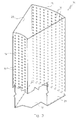
- Fig. 1 schematically shows in perspective and in partial section a heterogeneous catalytic reactor incorporating a catalytic cartridge according to the present invention;
- Fig. 2 shows in perspective, a catalytic cartridge according to the invention on an enlarged scale and on separated parts, which can be used for pseudoisothermal chemical reactors;
- Fig. 3 shows on an even larger scale a detail of figure 2;
- Fig. 4 shows an alternative embodiment of the detail of figure 3;
- Fig. 5 shows a heterogeneous catalytic reactor incorporating a catalytic cartridge according to an alternative embodiment of the present invention.
- With reference to figure 1, with 1 is indicated, as a whole and schematically, a heterogeneous catalytic reactor of the type comprising a cylindrical shell 2 (or pressure vessel), with a vertical axis, closed at the opposite ends by respective bottoms, upper 3 and lower 4, which form a single piece with
such shell 2 and that are equipped withpassages passages 7, 8 for possible operating fluids (like, for example, a heat exchange fluid), which are useful for controlling the chemical reaction which one intends to carry out, as described hereafter. More precisely, but not for limiting purposes, theaforementioned reactor 1 is of the type with a partial opening, in other words it is equipped, at the upper bottom plate 3, with amanhole 9 with a smaller diameter than the internal diameter of theshell 2, for accessing the inside of theshell 2. - Inside the
reactor 1, a reaction zone is defined in which a substantially cylindrical catalytic cartridge 10 (or catalytic bed) which is coaxial and concentric withsuch shell 2 is supported with per se known means which are not represented. Thecartridge 10 comprises abasket 11, with a structure and size to contain a predetermined amount of a predefined catalyst. - Depending on the chemical reaction to be carried out, on the method (adiabatic or pseudoisothermal) and technique preferred for carrying out said reaction, the
basket 11 must allow the reactant gases and the reaction products to pass through the catalytic mass loaded therein, in an axial direction, or in a radial or axial-radial direction, with reference to the axis of theshell 2. For such a purpose saidbasket 11 can be equipped with a perforated bottom wall and full side walls (in the case of axial crossing), or else a full bottom wall and perforated side walls (in the case of axial-radial crossing), or finally full upper and lower bottom walls and perforated side walls (in the case of radial crossing). - In the enclosed drawings, an application of the present invention to a
catalytic cartridge 10 that can be used in pseudoisothermal reactors of the so-called radial or axial-radial type, in other words a catalytic cartridge structured to allow the gases to pass through the catalytic mass in a radial or axial-radial direction, is illustrated for non-limiting purposes. In this case, saidcatalytic cartridge 10 can comprise, as will become clearer from the rest of the description, a possible heat exchange unit, fitted inside therespective basket 11, immersed in the catalyst, as well as possible devices used for controlling and regulating the operating parameters of the chemical reaction which one intends to carry out, like, for example, thermocouples, flow meters and pressure taps. In the case of the reactant gases and the gaseous reaction products passing radially through the catalyst, thebasket 11 has on the whole a cylindrical form with an annular cross section, suitable for defining a passage oraxial duct 11a, intended to receive the gaseous reaction products and to convey them outside of thereactor 1 or else to distribute the gaseous reactants in thebasket 11. - With reference to figures 2 and 3, in accordance with a feature of the present invention, said
basket 11 is made of a plurality ofcontainers 14 that are structurally independent from each other, which can be manipulated individually and are associated with each other in a reciprocally removable way. Eachcontainer 14 is of a size suitable for passing through saidmanhole 9. - According to another feature of this invention, each
container 14 is structured and configured as a cylinder sector, having anexternal wall 15 and aninternal wall 16, which are curvilinear (having the shape of the arc of a circle), coaxial and with convexity curving towards the outside of saidbasket 11, as well as a bottom 17. The aforementioned external and internal walls are equipped with respective pluralities ofholes side walls such basket 11, complete thecylinder sector container 14 under consideration. - Advantageously, each
cylinder sector container 14 has an axial length equal to that of saidbasket 11, but in particular cases it can be realised with an axial length which is a submultiple of or at least less than that of thebasket 11 which one intends to obtain. In this last case, two ormore containers 14 can be placed on top of each other so as to obtain a total axial length that is equal to that of thebasket 11. - The
baskets 14, filled with a predetermined catalyst outside of thereactor 1, are introduced one after the other in said reactor through themanhole 9 and are arranged in theshell 2, on an appropriate per se conventional support 22 (fig. 1). Saidcontainers 14 are fixed in a removable way onto thesupport 22 close to each other but preferably not in contact with each other laterally, in order to allow possible circumferential expansions of the containers themselves during the operation of thereactor 1. - When arranged for operation, the aforementioned
cylinder sector containers 14 define the plannedbasket 11, complete with outer and inner, cylindrical and perforated walls; moreover the internal wall ofsuch basket 11 is configured as an axialcylindrical pipe 11a. - In accordance with another feature of the present invention (fig. 4), inside each
container elements 25 are made of flattened plate-shaped exchangers with a rectangular configuration, substantially arranged in a radial way, with itslong sides 25a parallel to the axis of the respectivecylinder sector container 14 and itsshort side 25b extending radially. Preferably, theexchangers 25 of eachcylinder sector container 14 are mutually connected so as to constitute a unit that can be manipulated individually, the connection advantageously being made of collection and distribution ducts, 26 and 27, respectively, of a predetermined operating heat exchange fluid. The collection anddistribution ducts passages 7 and 8 of thereactor 1 for supplying and extracting operating fluids, respectively. To facilitate a centred and stable positioning of such a heat exchange unit in thebasket container 14, the lateral exchangers of such unit are equipped withspacers 28, of an appropriate size to rest against the side walls of saidcontainer 14. - Analogously,
possible devices 29 for the detection and control of the chemical-physical parameters of the chemical reaction that one intends to carry out can be fitted in thecontainers 14 in a removable way. - Still according to the example of figure 4, each
container 14 can advantageously be integrally equipped, at the internal wall, with asemi-cylindrical appendage 24, adapted to constitute aduct 23 for the supply into or else the extraction from therelative container 14 of the reactant gases or of the reaction products, respectively. - In figure 5, a
catalytic reactor 1 is shown incorporating acatalytic cartridge 10 according to an alternative embodiment of the present invention that comprises, in addition to thebasket 11, also a cylindricalannular basket 30 for containing a predetermined amount of catalyst. - In such a figure, the features of the
reactor 1 structurally and functionally equivalent to those illustrated in figure 1 are indicated with the same reference numbers and are not described any further. - In accordance with an advantageous feature of the present invention, the
basket 30 is of a suitable size to pass through themanhole 9 of thereactor 1. - Once filled with a predetermined catalyst outside of the
reactor 1, thebasket 30 is inserted into such reactor through themanhole 9 and is housed in the axialcylindrical duct 11a defined by the internal wall of thebasket 11. Such abasket 30 advantageously allows the reaction volume (catalytic mass) inside thereactor 1, and thus its capacity, to be increased. - Means per se known, and thus not represented, such as support beams, rings or shafts can be used to support the
basket 30 inside the axialcylindrical duct 11a. Preferably, the external diameter of thebasket 30 is less than the internal diameter of thebasket 11 so as to obtain a space between the baskets to allow possible circumferential expansions of the baskets themselves during the operation of thereactor 1. - In the same way as the
basket 11, thebasket 30 also allows - depending on the specific case - the reactant gases and the reaction products to pass through the catalytic mass loaded therein, in an axial direction or in a radial or axial-radial direction, with reference to the axis of theshell 2. For such a purpose, saidbasket 30 can be equipped with a perforated bottom wall and full side walls (in the case of axial crossing), or else a full bottom wall and perforated side walls (in the case of axial-radial crossing), or even full upper and bottom walls and perforated side walls (in the case of radial crossing). - Advantageously, the
basket 30 has an axial length equal to that ofsuch basket 11, but in particular cases it can be realised in a plurality of cylindrical annular containers placed one on the top of the another (not represented) having a submultiple axial length or which is anyhow inferior to that of thebasket 11. - The internal wall of the
basket 30 defines a cylindrical passage adapted to constitute aduct 23 for the supply into or else the extraction from the basket itself of the reactant gases or of the reaction products, respectively. It should be noted how in the case of a radial or axial-radial crossing of thecatalytic cartridge 10, thebaskets - The
cylinder sector containers 14 and thebasket 30 with the respective amount of catalyst loaded therein, theheat exchange elements 25 immersed in such catalyst and thepossible devices 29, fitted in such containers, constitute respective heat exchange units that can be manipulated individually, which are prepared outside the respective reactor with a partial opening and in which they are introduced, one after the other, through themanhole 9. Moreover, such units can favourably constitute "premanufactured" modular units. - The so conceived invention is subject to variations and changes, all falling within the scope of protection defined by the following claims.
Claims (14)
- Catalytic cartridge for heterogeneous chemical reactors of the type with a partial opening, comprising a substantially cylindrical basket (11), suitable for containing a predetermined amount of a predefined catalyst, characterized in that such basket (11) is modular and is made of a plurality of containers (14) that are structurally independent from each other, which can be manipulated individually and which are associated to form such basket (11) in a reciprocally removable way, each container (14) being of a suitable size to pass through said partial opening (9) of the corresponding reactor (1).
- Catalytic cartridge according to claim 1, characterized by the fact that each container (14) is substantially structured and configured as a cylinder sector.
- Catalytic cartridge according to claim 2, characterized by the fact that each cylinder sector container (14) has an axial length equal to or less than that of said basket (11).
- Catalytic cartridge according to claim 1, characterized by the fact that respective heat exchange elements (25) are fitted inside each container (14).
- Catalytic cartridge according to claim 4, characterized by the fact that at least part of such heat exchange elements (25) is made of exchangers of the so-called plate exchanger type.
- Catalytic cartridge according to claims 2 and 3, characterized by the fact that at least one respective plate exchanger having a flattened substantially rectangular configuration, arranged with the long side (25a) parallel to the axis of such container and with the short side (25b) extending radially with respect to it, is fitted inside each container (14).
- Catalytic cartridge according to claim 1, characterized by the fact that auxiliary devices (29) for controlling the chemical reaction that one intends to carry out in such reactor (1) are arranged in each container (14).
- Catalytic cartridge according to any one of the previous claims, characterized by the fact that it further comprises a cylindrical annular basket (30) for containing a predetermined amount of a predefined catalyst, being of a size suitable for passing through said partial opening (9) of the corresponding reactor (1) and to be housed in an axial duct (11a) defined by an internal wall of said substantially cylindrical basket (11).
- Modular unit to obtain catalytic beds (or cartridges) with a substantially cylindrical configuration, intended for chemical reactors (1) of the type with a partial opening (9), characterized by the fact that it comprises a container (14) for a portion of the predetermined amount of catalyst of a respective catalytic cartridge (10), substantially having a structure and configuration of a cylinder sector and being of a suitable size to pass through said partial opening (9) of the corresponding reactor (1).
- Modular unit to obtain catalytic cartridges (10) with a substantially cylindrical configuration and intended for pseudoisothermal chemical reactors (1) of the type with a partial opening (9), characterized by the fact that it comprises a container (14) for a portion of the predetermined amount of predefined catalyst for said catalytic cartridge (10), substantially having a cylinder sector configuration and being of a suitable size to pass through said partial opening (9) of the corresponding reactor (1), in said container (14) being defined a first external cylindrical wall (15), a second internal cylindrical wall (16) which is coaxial and concentric with said first wall (15), two side walls (20, 21) extending radially between said first and second wall (15, 16) and a bottom wall (17).
- Modular unit according to claim 10, characterized by the fact that said first and said second wall (15, 16) are equipped with respective pluralities of holes (18, 19), said side walls (20, 21) and said bottom wall (17) being full.
- Modular unit according to claim 11, characterized by the fact that at least one heat exchanger (25) is fitted in said container (14).
- Modular unit according to claim 12, characterized by the fact that said at least one heat exchanger (25) is plate-shaped, with a flattened substantially rectangular configuration.
- Modular unit according to claim 13, characterized by the fact that at least one auxiliary device 29 for controlling and regulating the parameters of the chemical reaction which one intends to carry out, is fitted in said container (14).
Priority Applications (14)
| Application Number | Priority Date | Filing Date | Title |
|---|---|---|---|
| EP01123804A EP1300190A1 (en) | 2001-10-04 | 2001-10-04 | Heterogeneous catalytic reactor with modular catalytic cartridge |
| MYPI20023522A MY138652A (en) | 2001-10-04 | 2002-09-23 | heterogeneous catalytic reactor with a modular catalytic cartridge |
| US10/450,348 US7314603B2 (en) | 2001-10-04 | 2002-10-02 | Heterogeneous catalytic reactor with a modular catalytic cartridge |
| BR0206058-2A BR0206058A (en) | 2001-10-04 | 2002-10-02 | Heterogeneous catalytic reactor with a modular catalytic support |
| EG2002101085A EG23245A (en) | 2001-10-04 | 2002-10-02 | Heterogeneous catalyst reactor with a modular catalytic cartridge. |
| CNB028032101A CN1263536C (en) | 2001-10-04 | 2002-10-02 | Heterogeneous Catalytic reactor with modular catalytic cartridge |
| CA002430618A CA2430618A1 (en) | 2001-10-04 | 2002-10-02 | Heterogeneous catalytic reactor with a modular catalytic cartridge |
| AU2002350479A AU2002350479A1 (en) | 2001-10-04 | 2002-10-02 | Heterogenous catalytic reactor with a modular catalytic cartridge |
| PCT/EP2002/011025 WO2003031048A1 (en) | 2001-10-04 | 2002-10-02 | Heterogeneous catalytic reactor with a modular catalytic cartridge |
| RU2003120450/12A RU2003120450A (en) | 2001-10-04 | 2002-10-02 | HETEROGENEOUS CATALYTIC SYNTHESIS REACTOR WITH THE CATALYST CONTAINER MODULAR TYPE CONTAINER |
| MXPA03004957A MXPA03004957A (en) | 2001-10-04 | 2002-10-02 | Heterogeneous catalytic reactor with a modular catalytic cartridge. |
| EP02785149A EP1432507B1 (en) | 2001-10-04 | 2002-10-02 | Heterogeneous catalytic reactor with a modular catalytic cartridge |
| DE60237215T DE60237215D1 (en) | 2001-10-04 | 2002-10-02 | HETEROGENIC CATALYTIC REACTOR WITH A MODULAR CATALYST CARTRIDGE |
| ARP020103742A AR036730A1 (en) | 2001-10-04 | 2002-10-03 | HETEROGENEO CATALYTIC REACTOR WITH A MODULAR CATALYTIC CARTRIDGE |
Applications Claiming Priority (1)
| Application Number | Priority Date | Filing Date | Title |
|---|---|---|---|
| EP01123804A EP1300190A1 (en) | 2001-10-04 | 2001-10-04 | Heterogeneous catalytic reactor with modular catalytic cartridge |
Publications (1)
| Publication Number | Publication Date |
|---|---|
| EP1300190A1 true EP1300190A1 (en) | 2003-04-09 |
Family
ID=8178851
Family Applications (2)
| Application Number | Title | Priority Date | Filing Date |
|---|---|---|---|
| EP01123804A Withdrawn EP1300190A1 (en) | 2001-10-04 | 2001-10-04 | Heterogeneous catalytic reactor with modular catalytic cartridge |
| EP02785149A Expired - Lifetime EP1432507B1 (en) | 2001-10-04 | 2002-10-02 | Heterogeneous catalytic reactor with a modular catalytic cartridge |
Family Applications After (1)
| Application Number | Title | Priority Date | Filing Date |
|---|---|---|---|
| EP02785149A Expired - Lifetime EP1432507B1 (en) | 2001-10-04 | 2002-10-02 | Heterogeneous catalytic reactor with a modular catalytic cartridge |
Country Status (13)
| Country | Link |
|---|---|
| US (1) | US7314603B2 (en) |
| EP (2) | EP1300190A1 (en) |
| CN (1) | CN1263536C (en) |
| AR (1) | AR036730A1 (en) |
| AU (1) | AU2002350479A1 (en) |
| BR (1) | BR0206058A (en) |
| CA (1) | CA2430618A1 (en) |
| DE (1) | DE60237215D1 (en) |
| EG (1) | EG23245A (en) |
| MX (1) | MXPA03004957A (en) |
| MY (1) | MY138652A (en) |
| RU (1) | RU2003120450A (en) |
| WO (1) | WO2003031048A1 (en) |
Cited By (19)
| Publication number | Priority date | Publication date | Assignee | Title |
|---|---|---|---|---|
| EP1681094A3 (en) * | 2005-01-17 | 2006-10-11 | Basf Aktiengesellschaft | Reactor with two or more separate reaction chambers |
| WO2006126702A1 (en) * | 2005-05-23 | 2006-11-30 | Honda Motor Co., Ltd. | Reformer |
| EP1892036A1 (en) * | 2006-08-21 | 2008-02-27 | Methanol Casale S.A. | Isothermal reactor |
| FR2924625A1 (en) * | 2007-12-06 | 2009-06-12 | Inst Francais Du Petrole | IMPROVING THE REACTOR AND THE PROCESS FOR ENDOTHERMIC REACTIONS IN THE GASEOUS PHASE |
| FR2924624A1 (en) * | 2007-12-06 | 2009-06-12 | Inst Francais Du Petrole | REACTOR AND METHOD FOR GASEOUS ENDOTHERMIC REACTIONS ON SOLID CATALYST |
| EP2070590A1 (en) * | 2007-12-11 | 2009-06-17 | Methanol Casale S.A. | Supporting system of heat-exchange plates in isothermal chemical reactors |
| WO2011048361A1 (en) * | 2009-10-19 | 2011-04-28 | Davy Process Technology Limited | Vessel for containing catalyst in a tubular reactor |
| WO2012146902A1 (en) * | 2011-04-27 | 2012-11-01 | Davy Process Technology Limited | Process for the production of anhydrides |
| WO2012146904A1 (en) * | 2011-04-27 | 2012-11-01 | Davy Process Technology Limited | Process for the synthesis of methanol |
| WO2012146903A1 (en) * | 2011-04-27 | 2012-11-01 | Davy Process Technology Limited | Fischer-tropsch process in a radial reactor |
| EP2686103A1 (en) * | 2011-03-16 | 2014-01-22 | ExxonMobil Research and Engineering Company | Modular catalyst bed support |
| WO2014122421A2 (en) * | 2013-02-08 | 2014-08-14 | Process Systems Enterprise Limited | Reactor and reaction method |
| EP2957339A1 (en) * | 2014-06-17 | 2015-12-23 | Casale SA | Radial flow horizontal catalytic reactor |
| WO2016186941A1 (en) * | 2015-05-18 | 2016-11-24 | Saudi Arabian Oil Company | Catalyst reactor basket |
| FR3036297A1 (en) * | 2015-05-20 | 2016-11-25 | Ifp Energies Now | THIN-CATALYTIC LAYER REACTOR WITH MOBILE BED-TYPE FLOW AND HEAT DELIVERY MADE USING BURNERS |
| FR3072305A1 (en) * | 2017-10-18 | 2019-04-19 | IFP Energies Nouvelles | REMOVABLE BASKET FOR CATALYTIC REACTOR |
| DE102018007737A1 (en) * | 2018-10-01 | 2020-04-02 | Hitachi Zosen Inova Etogas Gmbh | Fixed bed arrangement |
| EP3620231A4 (en) * | 2017-07-24 | 2020-05-06 | Athco Engineering (Shanghai) Co., Ltd. | Plate-type modular temperature control reactor |
| RU2771726C2 (en) * | 2017-10-18 | 2022-05-11 | Ифп Энержи Нувелль | Removable basket for catalytical reactor |
Families Citing this family (17)
| Publication number | Priority date | Publication date | Assignee | Title |
|---|---|---|---|---|
| EP1236505A1 (en) * | 2001-02-27 | 2002-09-04 | Methanol Casale S.A. | Method for carrying out chemical reactions in pseudo-isothermal conditions |
| US7146999B2 (en) * | 2005-03-08 | 2006-12-12 | Gregory C. Giese | Modular fluid handling device |
| CN100411768C (en) * | 2006-08-30 | 2008-08-20 | 无锡市东绛石油化工设备厂 | Continuous reforming reactor sector drum and its making method |
| US7726331B1 (en) | 2007-05-23 | 2010-06-01 | Giese Gregory C | Modular fluid handling device II |
| EP2354092A1 (en) * | 2010-01-29 | 2011-08-10 | Ammonia Casale S.A. | A method for modernizing the synthesis loop of an ammonia plant |
| DE202011050657U1 (en) * | 2011-07-07 | 2012-10-09 | Deg Engineering Gmbh | Reactor for the catalytic conversion of reaction media |
| CN102527298B (en) * | 2011-12-15 | 2014-09-03 | 昆明理工大学 | Circular ring type continuous feed fixed bed reactor |
| FR3017806B1 (en) * | 2014-02-27 | 2016-02-26 | Axens | MOBILE BED CATALYTIC REACTOR FOR FACILITATING CATALYST CIRCULATION INTERRUPTIONS AND METHOD USING THE SAME |
| USD768844S1 (en) | 2015-05-18 | 2016-10-11 | Saudi Arabian Oil Company | Catalyst basket |
| EP3124111A1 (en) * | 2015-07-29 | 2017-02-01 | Casale SA | Tube isothermal catalytic reactor |
| CN113368787B (en) * | 2015-11-09 | 2023-06-02 | 国际壳牌研究有限公司 | Easy-to-clean catalyst filter basket |
| EP3219384A1 (en) * | 2016-03-16 | 2017-09-20 | Casale SA | Walls for catalytic beds of radial- or axial-flow reactors |
| FR3063440B1 (en) * | 2017-03-01 | 2019-06-07 | IFP Energies Nouvelles | COMPARTIMIZED REACTOR WITH LOW CAPABILITY. |
| CN108854861A (en) * | 2017-05-09 | 2018-11-23 | 德艾柯工程技术(上海)有限公司 | A kind of modularization temperature control reactor |
| DE102017208319A1 (en) | 2017-05-17 | 2018-11-22 | Thyssenkrupp Ag | Radialstromeinsatzvorrichtung for predetermining at least one radial flow path in a bed reactor and assembly method and use |
| AR113649A1 (en) | 2017-12-20 | 2020-05-27 | Haldor Topsoe As | COOLED AXIAL FLOW CONVERTER |
| US11260356B2 (en) * | 2020-01-13 | 2022-03-01 | Saudi Arabian Oil Company | Catalyst testing process and apparatus |
Citations (5)
| Publication number | Priority date | Publication date | Assignee | Title |
|---|---|---|---|---|
| DE2016614A1 (en) * | 1970-04-08 | 1971-10-21 | Badische Anilin & Soda Fabrik AG, 6700 Ludwigshafen | Exothermic oxidation in catalytic reactor |
| US4102652A (en) * | 1975-10-01 | 1978-07-25 | Deggendorfer Werft Und Eisenbau Gmbh | Modular construction for a large catalytic reaction apparatus |
| US4225562A (en) * | 1979-05-14 | 1980-09-30 | Uop Inc. | Multi-bed catalytic reactor |
| EP0483975A1 (en) * | 1990-10-03 | 1992-05-06 | Nagaoka International Corporation | Device and method for holding catalyst in a radial flow reactor |
| EP0995491A1 (en) * | 1998-10-20 | 2000-04-26 | DEG Engineering GmbH | Reactor for the catalytic convertion of reaction media, in particular gaseous reaction media |
Family Cites Families (1)
| Publication number | Priority date | Publication date | Assignee | Title |
|---|---|---|---|---|
| EP1153653A1 (en) * | 2000-05-11 | 2001-11-14 | Methanol Casale S.A. | Reactor for exothermic or endothermic heterogeneous reactions |
-
2001
- 2001-10-04 EP EP01123804A patent/EP1300190A1/en not_active Withdrawn
-
2002
- 2002-09-23 MY MYPI20023522A patent/MY138652A/en unknown
- 2002-10-02 CN CNB028032101A patent/CN1263536C/en not_active Expired - Fee Related
- 2002-10-02 EG EG2002101085A patent/EG23245A/en active
- 2002-10-02 DE DE60237215T patent/DE60237215D1/en not_active Expired - Lifetime
- 2002-10-02 RU RU2003120450/12A patent/RU2003120450A/en not_active Application Discontinuation
- 2002-10-02 US US10/450,348 patent/US7314603B2/en not_active Expired - Fee Related
- 2002-10-02 AU AU2002350479A patent/AU2002350479A1/en not_active Abandoned
- 2002-10-02 CA CA002430618A patent/CA2430618A1/en not_active Abandoned
- 2002-10-02 WO PCT/EP2002/011025 patent/WO2003031048A1/en not_active Application Discontinuation
- 2002-10-02 BR BR0206058-2A patent/BR0206058A/en not_active Application Discontinuation
- 2002-10-02 EP EP02785149A patent/EP1432507B1/en not_active Expired - Lifetime
- 2002-10-02 MX MXPA03004957A patent/MXPA03004957A/en active IP Right Grant
- 2002-10-03 AR ARP020103742A patent/AR036730A1/en unknown
Patent Citations (5)
| Publication number | Priority date | Publication date | Assignee | Title |
|---|---|---|---|---|
| DE2016614A1 (en) * | 1970-04-08 | 1971-10-21 | Badische Anilin & Soda Fabrik AG, 6700 Ludwigshafen | Exothermic oxidation in catalytic reactor |
| US4102652A (en) * | 1975-10-01 | 1978-07-25 | Deggendorfer Werft Und Eisenbau Gmbh | Modular construction for a large catalytic reaction apparatus |
| US4225562A (en) * | 1979-05-14 | 1980-09-30 | Uop Inc. | Multi-bed catalytic reactor |
| EP0483975A1 (en) * | 1990-10-03 | 1992-05-06 | Nagaoka International Corporation | Device and method for holding catalyst in a radial flow reactor |
| EP0995491A1 (en) * | 1998-10-20 | 2000-04-26 | DEG Engineering GmbH | Reactor for the catalytic convertion of reaction media, in particular gaseous reaction media |
Cited By (56)
| Publication number | Priority date | Publication date | Assignee | Title |
|---|---|---|---|---|
| EP1681094A3 (en) * | 2005-01-17 | 2006-10-11 | Basf Aktiengesellschaft | Reactor with two or more separate reaction chambers |
| WO2006126702A1 (en) * | 2005-05-23 | 2006-11-30 | Honda Motor Co., Ltd. | Reformer |
| US8071045B2 (en) | 2005-05-23 | 2011-12-06 | Honda Motor Co., Ltd. | Reformer |
| EP1892036A1 (en) * | 2006-08-21 | 2008-02-27 | Methanol Casale S.A. | Isothermal reactor |
| WO2008022744A1 (en) * | 2006-08-21 | 2008-02-28 | Methanol Casale S.A. | Isothermal reactor |
| WO2009101278A1 (en) * | 2007-12-06 | 2009-08-20 | Ifp | Improvement to a reactor and to a method for gaseous phase endothermal reactions |
| WO2009101280A1 (en) * | 2007-12-06 | 2009-08-20 | Ifp | Reactor and method for gaseous phase endothermal reaction on a solid catalyst |
| FR2924624A1 (en) * | 2007-12-06 | 2009-06-12 | Inst Francais Du Petrole | REACTOR AND METHOD FOR GASEOUS ENDOTHERMIC REACTIONS ON SOLID CATALYST |
| FR2924625A1 (en) * | 2007-12-06 | 2009-06-12 | Inst Francais Du Petrole | IMPROVING THE REACTOR AND THE PROCESS FOR ENDOTHERMIC REACTIONS IN THE GASEOUS PHASE |
| EP2070590A1 (en) * | 2007-12-11 | 2009-06-17 | Methanol Casale S.A. | Supporting system of heat-exchange plates in isothermal chemical reactors |
| WO2009074212A1 (en) * | 2007-12-11 | 2009-06-18 | Methanol Casale S.A. | Supporting system of heat exchange plates in isothermal chemical reactors |
| CN101896260B (en) * | 2007-12-11 | 2013-03-27 | 卡萨尔甲醇公司 | Supporting system of heat exchange plates in isothermal chemical reactors |
| AU2008335963B2 (en) * | 2007-12-11 | 2013-03-28 | Methanol Casale S.A. | Supporting system of heat exchange plates in isothermal chemical reactors |
| WO2011048361A1 (en) * | 2009-10-19 | 2011-04-28 | Davy Process Technology Limited | Vessel for containing catalyst in a tubular reactor |
| EA021518B1 (en) * | 2009-10-19 | 2015-07-30 | Дэйви Проусесс Текнолоджи Лимитед | Catalyst carrier and use thereof in a tubular reactor |
| AU2010309565B2 (en) * | 2009-10-19 | 2015-03-19 | Johnson Matthey Davy Technologies Limited | Vessel for containing catalyst in a tubular reactor |
| AP3364A (en) * | 2009-10-19 | 2015-07-31 | Davy Process Techn Ltd | Vessel for containing catalyst in a tubular reactor |
| CN102574089A (en) * | 2009-10-19 | 2012-07-11 | 戴维加工技术有限公司 | Vessel for containing catalyst in a tubular reactor |
| CN102574089B (en) * | 2009-10-19 | 2014-07-23 | 戴维加工技术有限公司 | Vessel for containing catalyst in a tubular reactor |
| US8722747B2 (en) | 2009-10-19 | 2014-05-13 | Davy Process Technology Limited | Vessel for containing catalyst in a tubular reactor |
| EP2686103A1 (en) * | 2011-03-16 | 2014-01-22 | ExxonMobil Research and Engineering Company | Modular catalyst bed support |
| EP2686103A4 (en) * | 2011-03-16 | 2014-08-20 | Exxonmobil Res & Eng Co | Modular catalyst bed support |
| US8906970B2 (en) | 2011-04-27 | 2014-12-09 | Davy Process Technology Limited | Fischer-tropsch process in a radial reactor |
| WO2012146902A1 (en) * | 2011-04-27 | 2012-11-01 | Davy Process Technology Limited | Process for the production of anhydrides |
| US8785506B2 (en) | 2011-04-27 | 2014-07-22 | Davy Process Technology Limited | Process for the synthesis of methanol |
| AU2012205237B2 (en) * | 2011-04-27 | 2014-08-28 | Johnson Matthey Davy Technologies Limited | Fischer-Tropsch process in a radial reactor |
| AU2012211330B2 (en) * | 2011-04-27 | 2014-09-04 | Davy Process Technology Limited | Process for the synthesis of methanol |
| AU2012206976B2 (en) * | 2011-04-27 | 2014-11-06 | Davy Process Technology Limited | Process for the production of anhydrides |
| KR20140001732A (en) * | 2011-04-27 | 2014-01-07 | 데이비 프로세스 테크놀로지 리미티드 | Fischer-tropsch process in a radial reactor |
| US8937190B2 (en) | 2011-04-27 | 2015-01-20 | Davy Process Technology Limited | Process for the production of anhydrides |
| KR101872379B1 (en) | 2011-04-27 | 2018-06-28 | 존슨 매티 데이비 테크놀로지스 리미티드 | Fischer-tropsch process in a radial reactor |
| WO2012146903A1 (en) * | 2011-04-27 | 2012-11-01 | Davy Process Technology Limited | Fischer-tropsch process in a radial reactor |
| WO2012146904A1 (en) * | 2011-04-27 | 2012-11-01 | Davy Process Technology Limited | Process for the synthesis of methanol |
| EA024191B1 (en) * | 2011-04-27 | 2016-08-31 | Дэйви Проусесс Текнолоджи Лимитед | Process for the production of anhydrides |
| EA022045B1 (en) * | 2011-04-27 | 2015-10-30 | Дэйви Проусесс Текнолоджи Лимитед | Process for conversion of synthesis gas to higher hydrocarbons (variants) |
| AP3450A (en) * | 2011-04-27 | 2015-10-31 | Davy Process Techn Ltd | Process for the synthesis of methanol |
| WO2014122421A2 (en) * | 2013-02-08 | 2014-08-14 | Process Systems Enterprise Limited | Reactor and reaction method |
| EP4219662A1 (en) * | 2013-02-08 | 2023-08-02 | Siemens Process Systems Engineering Limited | Reactor and reaction method for reacting carbon monoxide and hydrogen in the presence of a carrier liquid to form a hydrocarbon product |
| US9816034B2 (en) | 2013-02-08 | 2017-11-14 | Process Systems Entreprise Limited | Reactor and reaction method |
| WO2014122421A3 (en) * | 2013-02-08 | 2015-02-19 | Process Systems Enterprise Limited | Reactor and reaction method for reacting carbon monoxide and hydrogen in the presence of a carrier liquid to form a hydrocarbon product |
| EP2957339A1 (en) * | 2014-06-17 | 2015-12-23 | Casale SA | Radial flow horizontal catalytic reactor |
| WO2015193106A1 (en) * | 2014-06-17 | 2015-12-23 | Casale Sa | Radial flow horizontal catalytic reactor |
| US10500556B2 (en) | 2014-06-17 | 2019-12-10 | Casale Sa | Radial flow horizontal catalytic reactor |
| WO2016186941A1 (en) * | 2015-05-18 | 2016-11-24 | Saudi Arabian Oil Company | Catalyst reactor basket |
| EP3501634A1 (en) * | 2015-05-18 | 2019-06-26 | Saudi Arabian Oil Company | Catalyst reactor basket |
| FR3036297A1 (en) * | 2015-05-20 | 2016-11-25 | Ifp Energies Now | THIN-CATALYTIC LAYER REACTOR WITH MOBILE BED-TYPE FLOW AND HEAT DELIVERY MADE USING BURNERS |
| EP3620231A4 (en) * | 2017-07-24 | 2020-05-06 | Athco Engineering (Shanghai) Co., Ltd. | Plate-type modular temperature control reactor |
| EP3473335A1 (en) * | 2017-10-18 | 2019-04-24 | IFP Energies nouvelles | Removable basket for catalytic reactor |
| FR3072305A1 (en) * | 2017-10-18 | 2019-04-19 | IFP Energies Nouvelles | REMOVABLE BASKET FOR CATALYTIC REACTOR |
| US10610844B2 (en) | 2017-10-18 | 2020-04-07 | IFP Energies Nouvelles | Removable basket for catalytic reactor |
| RU2771726C2 (en) * | 2017-10-18 | 2022-05-11 | Ифп Энержи Нувелль | Removable basket for catalytical reactor |
| DE102018007737A1 (en) * | 2018-10-01 | 2020-04-02 | Hitachi Zosen Inova Etogas Gmbh | Fixed bed arrangement |
| WO2020069974A1 (en) * | 2018-10-01 | 2020-04-09 | Hitachi Zosen Inova Etogas Gmbh | Fixed bed arrangement |
| CN113056326A (en) * | 2018-10-01 | 2021-06-29 | 日立造船爱诺瓦Eto气体有限公司 | Fixed bed device |
| US11673106B2 (en) | 2018-10-01 | 2023-06-13 | Hitachi Zosen Inova Ag | Fixed bed arrangement |
| CN113056326B (en) * | 2018-10-01 | 2023-10-27 | 日立造船爱诺瓦公司 | Fixed bed device |
Also Published As
| Publication number | Publication date |
|---|---|
| RU2003120450A (en) | 2005-03-10 |
| CA2430618A1 (en) | 2003-04-17 |
| DE60237215D1 (en) | 2010-09-16 |
| EP1432507A1 (en) | 2004-06-30 |
| MY138652A (en) | 2009-07-31 |
| AU2002350479A1 (en) | 2003-04-22 |
| US7314603B2 (en) | 2008-01-01 |
| MXPA03004957A (en) | 2004-12-06 |
| EG23245A (en) | 2004-09-29 |
| BR0206058A (en) | 2003-09-02 |
| CN1263536C (en) | 2006-07-12 |
| WO2003031048A1 (en) | 2003-04-17 |
| CN1477993A (en) | 2004-02-25 |
| EP1432507B1 (en) | 2010-08-04 |
| US20040018124A1 (en) | 2004-01-29 |
| AR036730A1 (en) | 2004-09-29 |
Similar Documents
| Publication | Publication Date | Title |
|---|---|---|
| EP1432507B1 (en) | Heterogeneous catalytic reactor with a modular catalytic cartridge | |
| US8071059B2 (en) | Chemical reactor | |
| AU2002233290B2 (en) | Catalytic reactor with heat exchanger for exothermic and endothermic heterogeneous chemical reactions | |
| CA2407907C (en) | Reactor for exothermic or endothermic heterogeneous reactions | |
| US7803331B2 (en) | Isothermal chemical reactor | |
| KR20200096929A (en) | Cooling axial flow transducer | |
| EP3328533B1 (en) | Tube isothermal catalytic reactor | |
| MX2007001173A (en) | Pseudo-isothermal radial reactor. | |
| US11040321B2 (en) | Adiabatic axial flow converter | |
| US7981271B2 (en) | Pseudo-isothermal radial reactor | |
| CN102755863A (en) | Axial and radial reactor of fixed bed with tube bank wall type internal and external barrels | |
| CN202700474U (en) | Static bed axial radical reactor with calandria wall type inner and outer barrels | |
| KR102660387B1 (en) | Adiabatic axial flow converter | |
| RU2371243C1 (en) | Catalytic reactor | |
| CN113613773A (en) | Method for retrofitting a catalytic converter |
Legal Events
| Date | Code | Title | Description |
|---|---|---|---|
| PUAI | Public reference made under article 153(3) epc to a published international application that has entered the european phase |
Free format text: ORIGINAL CODE: 0009012 |
|
| AK | Designated contracting states |
Kind code of ref document: A1 Designated state(s): AT BE CH CY DE DK ES FI FR GB GR IE IT LI LU MC NL PT SE TR Designated state(s): AT BE CH CY DE DK ES FI FR GB GR IE IT LI LU MC NL PT SE TR |
|
| AX | Request for extension of the european patent |
Extension state: AL LT LV MK RO SI |
|
| AKX | Designation fees paid | ||
| REG | Reference to a national code |
Ref country code: DE Ref legal event code: 8566 |
|
| STAA | Information on the status of an ep patent application or granted ep patent |
Free format text: STATUS: THE APPLICATION IS DEEMED TO BE WITHDRAWN |
|
| 18D | Application deemed to be withdrawn |
Effective date: 20031010 |