EP3501569A1 - Cannula insertion mechanism - Google Patents
Cannula insertion mechanism Download PDFInfo
- Publication number
- EP3501569A1 EP3501569A1 EP17209772.7A EP17209772A EP3501569A1 EP 3501569 A1 EP3501569 A1 EP 3501569A1 EP 17209772 A EP17209772 A EP 17209772A EP 3501569 A1 EP3501569 A1 EP 3501569A1
- Authority
- EP
- European Patent Office
- Prior art keywords
- cannula
- holder
- heating
- soft
- housing
- Prior art date
- Legal status (The legal status is an assumption and is not a legal conclusion. Google has not performed a legal analysis and makes no representation as to the accuracy of the status listed.)
- Withdrawn
Links
Images


Classifications
-
- A—HUMAN NECESSITIES
- A61—MEDICAL OR VETERINARY SCIENCE; HYGIENE
- A61M—DEVICES FOR INTRODUCING MEDIA INTO, OR ONTO, THE BODY; DEVICES FOR TRANSDUCING BODY MEDIA OR FOR TAKING MEDIA FROM THE BODY; DEVICES FOR PRODUCING OR ENDING SLEEP OR STUPOR
- A61M5/00—Devices for bringing media into the body in a subcutaneous, intra-vascular or intramuscular way; Accessories therefor, e.g. filling or cleaning devices, arm-rests
- A61M5/14—Infusion devices, e.g. infusing by gravity; Blood infusion; Accessories therefor
- A61M5/142—Pressure infusion, e.g. using pumps
- A61M5/14244—Pressure infusion, e.g. using pumps adapted to be carried by the patient, e.g. portable on the body
- A61M5/14248—Pressure infusion, e.g. using pumps adapted to be carried by the patient, e.g. portable on the body of the skin patch type
- A61M2005/14252—Pressure infusion, e.g. using pumps adapted to be carried by the patient, e.g. portable on the body of the skin patch type with needle insertion means
-
- A—HUMAN NECESSITIES
- A61—MEDICAL OR VETERINARY SCIENCE; HYGIENE
- A61M—DEVICES FOR INTRODUCING MEDIA INTO, OR ONTO, THE BODY; DEVICES FOR TRANSDUCING BODY MEDIA OR FOR TAKING MEDIA FROM THE BODY; DEVICES FOR PRODUCING OR ENDING SLEEP OR STUPOR
- A61M5/00—Devices for bringing media into the body in a subcutaneous, intra-vascular or intramuscular way; Accessories therefor, e.g. filling or cleaning devices, arm-rests
- A61M5/14—Infusion devices, e.g. infusing by gravity; Blood infusion; Accessories therefor
- A61M5/158—Needles for infusions; Accessories therefor, e.g. for inserting infusion needles, or for holding them on the body
- A61M2005/1585—Needle inserters
Landscapes
- Health & Medical Sciences (AREA)
- Dermatology (AREA)
- Vascular Medicine (AREA)
- Engineering & Computer Science (AREA)
- Anesthesiology (AREA)
- Biomedical Technology (AREA)
- Heart & Thoracic Surgery (AREA)
- Hematology (AREA)
- Life Sciences & Earth Sciences (AREA)
- Animal Behavior & Ethology (AREA)
- General Health & Medical Sciences (AREA)
- Public Health (AREA)
- Veterinary Medicine (AREA)
- Infusion, Injection, And Reservoir Apparatuses (AREA)
Abstract
Die Erfindung betrifft einen Insertionsmechanismus für eine Kanüle (7, 8) mit: einem Kanülengehäuse (1), relativ zu welchem die Kanüle (7, 8) verschoben werden kann; einem Kanülenhalter (2.2, 3.2), an welchem die Kanüle (7, 8) befestigbar ist und welcher relativ zum Kanülengehäuse (1) bewegbar ist; einem Insertions-Energiespeicher (4) zum Erzeugen einer Insertionskraft auf den einen Kanülenhalter (2.2, 3.2) und zum Erzeugen einer Freigabekraft auf ein Halteelement (1.1); einem Halteelement (1.1), welcher den Kanülenhalter (2.2, 3.2) gegen die vom Insertions-Energiespeicher (4) erzeugte Kraft relativ zum Kanülengehäuse (1) halten kann; und einer Sicherung (9), welche das Halteelement (1.1) im Sicherungszustand gegen eine Kraft des Insertions-Energiespeichers (4) in Sperrstellung hält und im ausgelösten Zustand das Halteelement (1.1) freigibt, sodass das Halteelement (1.1) durch die Kraft des Insertions-Energiespeichers (4) in Freigabestellung bewegt werden kann und sich der Kanülenhalter (2.2, 3.2) angetrieben durch den Insertions-Energiespeicher (4) relativ zum Kanülengehäuse (1) bewegen kann, um eine Insertionsbewegung auszulösen.

Description
Die vorliegende Erfindung betrifft eine Vorrichtung zur Verabreichung einer Substanz, zum Beispiel einer flüssigen medizinischen Substanz, welche mittels einer Kanüle, die in einen Körper eingebracht wird, abgegeben wird. Insbesondere betrifft die Erfindung einen Mechanismus zur automatischen Insertion einer Kanüle, mit welchem eine Kanüle automatisch in einen Körper eingestochen werden kann, indem diese zum Beispiel aus einer Verabreichungsvorrichtung oder einem Kanülengehäuse ausgestoßen wird. Nach dem Eindringen der Kanüle in einen Körper kann eine medizinische Substanz, wie zum Beispiel Insulin, durch die Kanüle dosiert an den Körper abgegeben werden.The present invention relates to a device for administering a substance, for example a liquid medicinal substance, which is delivered by means of a cannula which is introduced into a body. In particular, the invention relates to a mechanism for automatically inserting a cannula, with which a cannula can be automatically inserted into a body by, for example, ejecting it from an administering device or a cannula housing. After penetration of the cannula into a body, a medicinal substance, such as insulin, may be delivered to the body through the cannula.
Zur Verabreichung einer medizinischen Substanz oder Flüssigkeit wird häufig eine an sich bekannte Spritze, ein Injektionspen oder eine Infusionspumpe verwendet. Die Infusionspumpe kann an ein Infusionsset oder einen Katheter angeschlossen werden, um die Flüssigkeit dosiert abzugeben. Eine Möglichkeit der kontrollierten Substanzverabreichung ist die Abgabe durch eine externe Pumpe an einen Patienten, welche zum Beispiel an dem Patienten getragen oder auf dessen Haut aufgeklebt wird, wobei die abzugebende Substanz aus der Pumpe durch einen in den Körper des Patienten eingebrachten Katheter abgegeben wird.For administration of a medicinal substance or liquid, a per se known syringe, a Injektionspen or an infusion pump is often used. The infusion pump can be connected to an infusion set or catheter to dose the fluid. One possibility of controlled substance administration is delivery by an external pump to a patient, for example, worn on the patient or adhered to the skin, the substance to be dispensed being discharged from the pump through a catheter inserted into the body of the patient.
Das Einbringen eines Katheters oder Kanüle kann manuell, zum Beispiel mittels eines an sich bekannten Infusionssets, erfolgen. Alternativ zum manuellen Setzen einer Kanüle ist auch eine automatische Kanüleneinbringvorrichtung bekannt.The introduction of a catheter or cannula can be done manually, for example by means of a known infusion set. As an alternative to manually setting a cannula, an automatic cannula inserting device is also known.
Die
Ausführungsformen der erfindungsgemäßen Vorrichtung können einen oder mehrere der folgenden Vorteile bieten: Eine sichere Lagerung, insbesondere eine sichere Langzeitlagerung der Vorrichtung. Eine sichere Auslösung der Insertion, insbesondere bei durch langzeitigen Druck oder Zug beaufschlagten Komponenten. Immunität bezüglich Beschleunigungen, wie sie z.B. bei einem Fall oder Stoß auftreten können. Eine einfache automatische z.B. durch ein elektrisches Signal ausgelöste Ansteuerung, wie z.B. eine Auslösung einer Insertion. Erhöhung der Montageprozesssicherheit. Verringerung des für den Halte- oder Auslösemechanismus benötigten Platzbedarfs.Embodiments of the device according to the invention may offer one or more of the following advantages: Safe storage, in particular secure long-term storage of the device. Safe triggering of insertion, especially in the case of components subjected to long-term pressure or tension. Immunity to accelerations, e.g. can occur in a case or shock. A simple automatic e.g. triggered by an electrical signal, such as e.g. a triggering of an insertion. Increase assembly process security. Reduction of the space required for the holding or release mechanism.
Sofern nachfolgend auf eine Kanüle Bezug genommen wird, ist hierunter sowohl eine einzelne Kanüle, also beispielsweise eine Softkanüle, oder alternativ auch ein Mehr-Elemente-System zu verstehen, wie beispielsweise eine Hartkanüle, Stahlkanüle oder Nadel, welche von zum Beispiel einer Softkanüle (z.B. aus elastischem Kunststoff) umgeben wird. In letzterem Fall kann bei der Insertion beispielsweise die die Hartkanüle umgebende Softkanüle zusammen mit dieser in ein Gewebe eingestochen werden und nach der Insertion kann die relativ zur Softkanüle verschiebbare Hartkanüle innerhalb der Softkanüle zurück und beispielsweise aus dem Gewebe herausgezogen werden, wobei die Softkanüle in dem Gewebe bleibt. Ein Fluid, welches beispielsweise an dem Einstichort (= distales Ende) abgewandten Ende der Hartkanüle (proximal) in diese eintritt, kann durch die Hartkanüle hindurchtreten und tritt an der distalen Austrittsöffnung der Hartkanüle in den Innenraum der die Hartkanüle umgebenden Softkanüle ein und wird von der Softkanüle weitergeleitet, bis es am distalen Ende der Softkanüle abgegeben wird. Die Softkanüle liegt mit ihrem Innenumfang dichtend am Außenumfang der Hartkanüle an, sodass keine Flüssigkeit durch den Bereich hindurchtreten kann, an welchem sich Hartkanüle und Softkanüle berühren. Dabei ist die Hartkanüle vorzugsweise innerhalb der Softkanüle, welche beispielsweise aus einem Kunststoff oder verformbaren Material geformt ist, verschiebbar. Beide, Soft- und Hartkanüle, sind bevorzugt biegbar, also können z.B. in ihrer Längsrichtung gebogen oder gekrümmt werden. Alternativ kann, bei ansonsten gleicher und dichtender Ausgestaltung, die Hartkanüle außerhalb der Softkanüle angeordnet sein.If reference is made below to a cannula, this is to be understood as meaning both a single cannula, for example a soft cannula, or alternatively also a multi-element system, such as a hard cannula, steel cannula or needle, for example a soft cannula (eg made of elastic plastic) is surrounded. In the latter case, during insertion, for example, the soft cannula surrounding the hard cannula can be inserted into a tissue and after insertion, the hard cannula displaceable relative to the soft cannula can be withdrawn inside the soft cannula and, for example, out of the tissue, the soft cannula in the tissue remains. A fluid, which for example at the puncture site (= distal end) remote end of the hard cannula (proximal) enters this, can pass through the hard cannula and enters at the distal outlet opening of the hard cannula into the interior of the soft cannula surrounding the soft cannula and is of the Soft cannula forwarded until it is discharged at the distal end of the soft cannula. The soft cannula lies with its inner circumference sealingly on the outer circumference of the hard cannula, so that no liquid can pass through the area at which the hard cannula and soft cannula touch. In this case, the hard cannula is preferably displaceable within the soft cannula, which is formed, for example, from a plastic or deformable material. Both, soft and hard cannula, are preferably bendable, so for example, can be bent in their longitudinal direction or to be curved. Alternatively, with otherwise identical and sealing design, the hard cannula can be arranged outside the soft cannula.
Gemäß einem ersten Aspekt betrifft die Erfindung einen Insertionsmechanismus für eine Kanüle, die beispielsweise als Softkanüle oder wie oben erwähnt als Hartkanüle mit umgebender Softkanüle oder nur als Hartkanüle ausgebildet sein kann. Die Kanüle ist verschiebbar relativ zu einem Kanülengehäuse gelagert, sodass die Kanüle beispielsweise relativ zu dem Kanülengehäuse beschleunigt oder z.B. aus dem Kanülengehäuse automatisch ausgefahren oder ausgestoßen werden kann. Das Kanülengehäuse kann eine die Kanüle teilweise oder vollständig umgebende Struktur sein, welche eine oder eine Mehrzahl von Öffnungen aufweisen kann, wobei die Kanüle beispielsweise auch vollständig oder zum Teil außerhalb des Kanülengehäuses geführt werden kann. Die Kanüle ist an mindestens einem Kanülenhalter befestigt, welcher relativ zum Kanülengehäuse verschoben werden kann, um so einen Ausschub oder Einstich der Kanüle zu bewirken. Der oder jeder Kanülenhalter ist relativ zum Kanülengehäuse und beispielsweise im Kanülengehäuse beweglich und kann beispielsweise in eine Kanülenvorschubrichtung und eine Kanülenrückzugsrichtung verschoben werden, wobei die Einstichrichtung der Kanüle auf Grund einer Kanülenkrümmung auch von der Kanülenvorschubrichtung oder Kanülenrückzugsrichtung abweichen oder davon verschieden sein kann. Die mit dem mindestens einen Kanülenhalter verbundene mindestens eine Kanüle kann in distaler axialer Richtung relativ zum Haltepunkt an dem Kanülenhalter geradlinig weiterverlaufen oder geführt sein und kann auch eine oder mehrere Krümmungen oder Biegungen aufweisen, sodass die Kanüle beispielsweise entlang oder in Fortsetzung eines Verschiebeweges des Kanülenhalters z.B. entlang des Kanülengehäuses geradlinig geführt und im weiteren Verlauf gekrümmt und anschließend wieder geradlinig geführt ist. Mindestens ein Energiespeicherelement zum Erzeugen einer Insertionsbewegung des Kanülenhalters und damit zum Erzeugen einer Insertionsbewegung der Kanüle kann den Kanülenhalter mit einer Kraft in Richtung Vorschub- oder der Insertionsbewegung beaufschlagen, um nach Auslösung des Energiespeicherelements eine automatische Insertion durchführen zu können. Das Energiespeicherelement kann beispielsweise mindestens eine vorgespannte Druckfeder, z.B. auch mehrere parallel oder seriell angeordnete Federn, oder alternativ auch eine oder mehrere Zugfedern sein, welche beispielsweise funktional zwischen dem Kanülengehäuse und dem Kanülenhalter vorgesehen ist und optional mit einem oder beiden dieser Elemente auch verbunden sein kann. Das Energiespeicherelement kann auch ein anderes mechanisches oder hydraulisches oder pneumatisches Element oder ein magnetischer, elektromagnetischer oder elektromechanischer Antrieb sein, welcher den Kanülenhalter relativ zum Kanülengehäuse bewegen kann.According to a first aspect, the invention relates to an insertion mechanism for a cannula, which may be designed, for example, as a soft cannula or, as mentioned above, as a hard cannula with a surrounding soft cannula or only as a hard cannula. The cannula is slidably mounted relative to a cannula housing, so that the cannula, for example, accelerated relative to the cannula housing or, for example, automatically extended or ejected from the cannula housing. The cannula housing may be a structure partially or completely surrounding the cannula, which may have one or a plurality of openings, wherein the cannula may also be guided completely or partly outside the cannula housing, for example. The cannula is attached to at least one cannula holder, which can be displaced relative to the cannula housing, so as to cause an expulsion or puncture of the cannula. The or each cannula holder is movable relative to the cannula housing and, for example, in the cannula housing and can be displaced, for example, in a cannula advancing direction and a cannula retracting direction, wherein the piercing direction of the cannula due to a cannula curvature may be different or different from the cannula advancing direction or cannula retraction direction. The at least one cannula connected to the at least one cannula holder can continue to run rectilinearly in the distal axial direction relative to the holding point on the cannula holder and can also have one or more curves or bends, so that the cannula for example along or in continuation of a displacement path of the cannula holder guided in a straight line along the cannula housing and curved in the further course and then guided straight again. At least one energy storage element for generating an insertion movement of the cannula holder and thus for generating an insertion movement of the cannula can act on the cannula holder with a force in the direction of advancing or insertion movement to perform an automatic insertion after triggering of the energy storage element can. The energy storage element may be, for example, at least one prestressed compression spring, for example a plurality of parallel or serially arranged springs, or alternatively also one or more tension springs, which is provided, for example, functionally between the cannula housing and the cannula holder and may optionally also be connected to one or both of these elements , The energy storage element can also be another mechanical or hydraulic or be a pneumatic element or a magnetic, electromagnetic or electromechanical drive which can move the needle holder relative to the cannula housing.
Der Energiespeicher wird von einem Sperr- oder Rückhalteelement an seiner Entladung oder Entspannung oder an der Freisetzung der permanent wirkenden Kraft gehindert, wobei das Sperr- oder Rückhalteelement unmittelbar auf den Energiespeicher oder mittelbar auf den Energiespeicher, zum Beispiel auf den Kanülenhalter, wirken kann, um den Energiespeicher oder Kanülenhalter im gesperrten Zustand an einer Bewegung in Insertionsrichtung zu hindern. Das Sperr- oder Halteelement kann als einzelnes Element, z.B. als Federarm, oder zusammengesetzt aus zwei oder mehr Teilelementen, z.B. zwei oder mehr Federarmen, ausgebildet sein, welche gemeinsam und/oder jeweils einzeln den Insertions-Energiespeicher sichern oder sperren, also an einer Entladung und Energieübertragung hindern, können. Das Sperr- oder Halteelement kann auch eine mechanische Übersetzung oder Untersetzung aufweisen und z.B. als Reduktionsgetriebe zur Reduktion oder Verringerung der zu haltenden Kraft ausgebildet sein. Dabei kann das Reduktionsgetriebe einstufig, zweistufig oder mehrstufig ausgebildet sein und z.B. Zahnräder und/oder Gewindeelemente zur Realisierung der Untersetzung aufweisen. Ein z.B. schmelzbares, erweichbares oder schwächbares Sicherungselement zum Sichern des Sperr- oder Halteelements kann ebenfalls zwei oder mehrfach vorgesehen sein, um die entsprechende Anzahl an Sperrelementen zu sichern. Die Erweichung oder Schwächung kann z.B. durch Temperaturerhöhung herbeigeführt werden. Das Material muss nicht zwingend flüssig werden. Zum Beispiel geht beim Überschreiten der Glasübergangstemperatur Tg ein fester amorpher Stoff oder festes Glas oder Polymer in einen gummiartigen bis zähflüssigen Zustand über, wodurch die Sperr- oder Haltefunktion aufgehoben werden kann.The energy storage is prevented by a blocking or retaining element at its discharge or relaxation or the release of the permanently acting force, wherein the blocking or retaining element can act directly on the energy storage or indirectly on the energy storage, for example on the needle holder to to prevent the energy storage or cannula holder in the locked state from moving in the insertion direction. The blocking or retaining element can be designed as a single element, e.g. as a spring arm, or composed of two or more sub-elements, e.g. two or more spring arms, be formed, which together and / or individually secure the insertion energy storage or lock, so prevent a discharge and energy transfer, can. The blocking or retaining element may also have a mechanical translation or reduction and e.g. be designed as a reduction gear to reduce or reduce the force to be held. In this case, the reduction gear can be formed in one stage, two stages or multi-stage and e.g. Have gears and / or threaded elements for the realization of the reduction. An e.g. fusible, softenable or weakenable securing element for securing the blocking or holding element can also be provided two or more times to secure the appropriate number of locking elements. The softening or weakening may e.g. be brought about by raising the temperature. The material does not necessarily have to be liquid. For example, when the glass transition temperature Tg is exceeded, a solid amorphous substance or solid glass or polymer turns into a rubbery to viscous state, whereby the blocking or holding function can be canceled.
Dabei wird gemäß einer optionalen Ausführungsform beispielsweise das Sperr- oder Rückhalteelement von dem Insertions-Energiespeicher permanent mit einer Kraft beaufschlagt, die das Rückhalteelement in Freigabestellung drückt, sodass das Rückhalteelement beispielsweise von einer Sicherung in der Sperrstellung gehalten werden muss, um die Insertion nicht auszulösen. Beispielsweise kann das Rückhalteelement oder Halteelement ein Hebel oder allgemein eine Struktur sein, auf welche die Kraft des Insertions-Energiespeichers im gesicherten und nicht ausgelösten Zustand wirkt, wobei die Sicherung ohne einen weiteren Antrieb, also zum Beispiel ohne eine weitere Feder, allein durch die Kraft des Insertions-Energiespeichers, wie beispielsweise einer Insertionsfeder, aus der Sperrposition weggedrückt werden könnte, um so den Kanülen-Insertionsvorgang freizugeben oder auszulösen, wenn das Rückhalteelement oder Halteelement nicht durch die Sicherung gesichert wäre, welche das Halteelement in Sperrposition hält. Der Insertionsvorgang kann somit beispielsweise mit nur einem einzigen Energiespeicher, wie beispielsweise einer einzigen Insertionsfeder, durchgeführt werden, welche einerseits die Energie für die Insertion, also beispielsweise den Vorschub der mindestens einen Kanüle, zur Verfügung stellt und welche andererseits die Energie zur Verfügung stellt, um das Halteelement aus der Halteposition wegzudrücken, nachdem die Sicherung das Halteelement freigegeben hat, also beispielsweise eine Bewegung des Halteelementes aus der Sperrstellung in eine Freigabestellung durch den Druck der Insertionsfeder ermöglicht hat. Alternativ kann das Sperr- oder Halteelement auch nicht vom Insertions-Energiespeicher mit einer Kraft beaufschlagt werden. Optional kann hierzu z.B. ein weiterer Energiespeicher oder eine weitere Feder vorgesehen sein, wie z.B. in der
Das Sicherungselement, welches das Halteelement oder Auslöseelement des Insertions-Energiespeichers in Sperrstellung hält und zum Beispiel dessen Auslenkung zur Freigabe oder Durchführung der Insertion verhindert, kann gemäß einer Ausführungsform ein Element aus einem schmelzbaren, erweichbaren oder schwächbaren Material, wie zum Beispiel ein Kunststoffelement oder ein festes Glas oder Polymer sein, welches zum Beispiel elektrisch nicht leitfähig oder alternativ auch elektrisch leitfähig sein kann. Das feste Glas, der feste amorphe Stoff oder das Polymer kann in einen gummiartigen bis zähflüssigen Zustand übergehen, wenn die Glasübergangstemperatur Tg überschritten wird. Eine Schmelztemperatur muss nicht zwingend erreicht werden. Das schmelzbare, erweichbare oder schwächbare Element kann gemäß einer Ausführungsform auf Zug belastet sein, wobei die Zugkraft beispielsweise durch den Insertions-Energiespeicher verursacht wird, welcher direkt oder mittelbar auf das Halteelement drückt, welches mit der Sicherung oder dem schmelzbaren, erweichbaren oder schwächbaren Element gekoppelt oder verbunden ist.The securing element, which holds the holding element or triggering element of the insertion energy storage in blocking position and, for example, prevents its deflection to release or carry out the insertion, according to one embodiment, an element of a meltable, softenable or weakenable material, such as a plastic element or a solid glass or polymer, which may be, for example, electrically non-conductive or alternatively electrically conductive. The solid glass, solid amorphous substance or polymer may change to a rubbery to viscous state when the glass transition temperature Tg is exceeded. A melting temperature does not necessarily have to be achieved. According to one embodiment, the fusible, softenable or weakenable element can be subjected to tension, wherein the tensile force is caused, for example, by the insertion energy store, which presses directly or indirectly on the holding element, which is coupled to the fuse or the fusible, softenable or weakenable element or connected.
Das mindestens eine Sicherungselement kann stoffschlüssig und/oder formschlüssig mit dem oder den Halteelementen oder Auslöseelementen verbunden sein. Eine stoffschlüssige Verbindung ermöglicht einen einfachen und sicheren Aufbau sowie ein sicheres langfristiges Halten des Insertions-Energiespeichers.The at least one securing element can be materially and / or positively connected to the one or more holding elements or triggering elements. A cohesive connection allows a simple and safe construction as well as a secure long-term hold of the insertion energy storage.
Am aufweichbaren oder schmelzbaren Element oder in dessen Nähe ist mindestens ein Erwärmungs- oder Heizelement vorgesehen, wie zum Beispiel ein Heizdraht, Heizwendel oder eine Heizfläche, welches z.B. bei Stromdurchfluss Wärme erzeugt, um das schmelzbare Element durch Erwärmung zumindest teilweise oder vollständig aufweichen oder schmelzen zu können. Wenn das schmelzbare oder aufweichbare Element bedingt durch eine Erwärmung in seiner Haltefähigkeit, z.B. zum Halten einer Zugkraft oder einer Druckkraft oder einer Scherkraft, geschwächt oder durchgeschmolzen ist, also z.B. an einer Stelle zerteilt, gibt dieses das mit ihm gekoppelte Haltelement frei, sodass der Insertions-Energiespeicher den nicht mehr gesicherten mindestens einen Kanülenhalter relativ zum Kanülengehäuse bewegen und so die Insertionsbewegung beginnen kann. Zur Auslösung der Insertion ist es nicht erforderlich, dass das schmelzbare oder erweichbare Element vollständig durchgeschmolzen wird, da ein z.B. auf Zug beanspruchtes Element zum Beispiel in seiner Haltefähigkeit nur soweit geschwächt werden muss, dass eine anliegende Zugkraft nicht mehr gehalten werden kann und sich beispielsweise ein Halteende des schmelzbaren oder erweichbaren Elementes soweit bewegen oder verschieben kann, dass ein Halteelement aus einer Sperrstellung in die Freigabestellung gebracht wird. Dabei kann es möglich sein, dass das erweichbare oder schmelzbare Element zum Beispiel durch Erwärmung aufgeweicht wird und ein Verlängern oder sogar Durchtrennen oder Aufreißen des schmelzbaren Elementes erst durch die Kraft des auf das schmelzbare Element wirkenden Injektions-Energiespeichers bewirkt wird. Ein vollständiges Durchtrennen des aufweichbaren oder schmelzbaren Elementes, welches auch als Schmelzsicherung bezeichnet werden kann, ist jedoch nicht zwingend erforderlich.At or near the softenable or fusible element is provided at least one heating or heating element, such as a heating wire, heating coil or heating surface, e.g. generates heat when current flows in order to at least partially or completely soften or melt the fusible element by heating. When the fusible or softenable element, due to heating in its holding ability, e.g. for holding a tensile or compressive force or a shear force, weakened or fused, e.g. at one point, this releases the holding element coupled to it, so that the insertion energy store can move the no longer secured at least one cannula holder relative to the cannula housing and thus begin the insertion movement. To initiate the insertion, it is not necessary that the fusible or softenable element be completely melted through, as e.g. To train claimed element, for example in its holding ability only needs to be weakened so that an applied tensile force can not be maintained and, for example, a holding end of the fusible or softenable element move or move so far that a holding element from a blocking position brought into the release position becomes. It may be possible that the softenable or fusible element is softened, for example by heating and extending or even severing or tearing of the fusible element is effected only by the force of the force acting on the fusible element injection energy storage. However, a complete severing of the softenable or fusible element, which may also be referred to as a fuse, is not absolutely necessary.
Das schmelzbare oder aufweichbare Element oder Schmelzsicherungselement ist z.B. an einer Seite fest gelagert, z.B. fest am oder unbewegbar relativ zum Kanülengehäuse vorgesehen und zum Beispiel an einer Schmelzsicherungs-Halterung befestigt. An dem der Halterung gegenüberliegenden Ende des Schmelzsicherungselementes kann die Schmelzsicherung mit einem Sperr- oder Halteelement des Energiespeichers gekoppelt sein, welches optional selbst von dem Insertions-Energiespeicher mit einer Kraft beaufschlagt werden kann, welche diesen aus der Sperrstellung in eine Freigabestellung drücken kann, sodass diese Kraft z.B. als Zugkraft oder Druckkraft auf das Schmelzsicherungselement wirken kann. Das Sicherungselement kann auch in zwei gegenüberliegende Richtungen belastet werden, beispielsweise von zwei Federarmen.The fusible or softenable element or fuse element is for example fixedly mounted on one side, eg fixedly provided on or immovably relative to the cannula housing and fastened, for example, to a fuse holder. At the end of the fuse element opposite the holder, the fuse may be coupled to a blocking or holding element of the energy store, which may optionally be acted upon by the insertion energy storage with a force which can push it from the blocking position into a release position, so that they For example, force can act as a tensile force or compressive force on the fuse element. The securing element can also be loaded in two opposite directions, for example by two spring arms.
Gemäß einer weiteren Ausführungsform kann die Schmelzsicherung aus einem elektrisch leitenden (i.e. mit passendem elektrischen Widerstand) und aufweichbaren oder schmelzbaren Material bestehen, welches wie oben für die Schmelzsicherung beschrieben mit dem Sperr- oder Halteelement des Insertions-Energiespeichers gekoppelt und zum Beispiel auf Zug oder alternativ auf Druck belastet ist. Zur Auslösung der Insertion, also zur Freigabe des Sperr- oder Halteelements durch Bewegung der Schmelzsicherung oder eines Teils oder Endes davon, bedingt durch Aufweichung oder Schmelzung, kann eine elektrische Spannung angelegt werden, durch welche ein Strom durch das aufweichbare oder schmelzbare und elektrisch leitende Material, wie zum Beispiel elektrisch leitender Kunststoff oder ein leicht aufweichbares Metall, fließt und hierdurch eine Erwärmung verursacht.According to a further embodiment, the fuse may consist of an electrically conductive (ie with suitable electrical resistance) and softenable or fusible material which, as described above for the fuse, is coupled to the blocking or holding element of the insertion energy store and, for example, to train or alternatively loaded on pressure. To trigger the insertion, ie to release the blocking or holding element by movement of the fuse or a part or end thereof, due to softening or melting, an electrical voltage can be applied, through which a current through the softenable or meltable and electrically conductive material , such as electrically conductive plastic or an easily softenable metal, flows and thereby causes heating.
Sofern ein Sicherungselement, welches ein Sperr- oder Halteelement des Insertions-Energiespeichers in Sperrstellung hält, auf Zug beansprucht ist, kann es als flächiges oder stabförmiges Element ausgebildet sein und kann zum Beispiel eine Verjüngung oder Solltrennstelle aufweisen, welche bei Erwärmung einfach und z.B. mit möglichst geringem Energieaufwand aufzuweichen und zum Beispiel zu verlängern oder durchzutrennen ist.If a securing element, which holds a blocking or holding element of the insertion energy storage in the blocking position, is claimed to train, it may be formed as a flat or rod-shaped element and may for example have a taper or Solltrennstelle, which when heated easily and e.g. softened with the least possible expenditure of energy and, for example, to extend or durchzutrennen is.
Gemäß einem anderen Aspekt der Erfindung wird das Sperr- oder Halteelement des Insertions-Energiespeichers gesichert, indem ein aufweichbares oder schmelzbares Element verwendet wird, das auf Druck belastet wird. Das Halteelement, welches wie oben beschrieben bedingt durch den Druck (oder alternativ durch eine Zugkraft) des Insertions-Energiespeichers von der Sperrstellung in die Freigabestellung gelangen will, wird in der Sperrstellung durch ein aufweichbares oder schmelzbares Element gehalten oder in die Sperrstellung gedrückt. Das das Sperr- oder Halteelement sichernde Element besteht zumindest teilweise oder vollständig aus einem aufweichbaren oder schmelzbaren Material, wie zum Beispiel Kunststoff oder Metall, welches durch Erwärmung aufgeweicht oder zumindest zum Teil zum Schmelzen gebracht wird. Dabei ist dieses Material zwischen dem auf dieses Material drückenden Sperr- oder Halteelement und einem dem Anlagepunkt zum Halteelement gegenüberliegenden Gegendruckpunkt oder Abstützungspunkt so angeordnet, dass sich das Sicherungsmaterial an dem Abstützungspunkt, welcher beispielsweise fest am oder im oder unbewegbar relativ zum Kanülengehäuse vorgesehen ist, abstützt. Das sichernde Material wird vorzugsweise in einem Bereich zwischen dem Kontakt zum Sperr- oder Halteelement einerseits und zum Abstützungspunkt andererseits so geführt, dass das sichernde Material verschiebbar gelagert ist, also dass es sich zum Beispiel vom Halteelement wegbewegen könnte, wenn der Abstützpunkt nicht vorhanden wäre oder wenn die Länge des sichernden Materials verkürzt würde. Eine Verkürzung der Länge des sichernden Materials kann zum Beispiel dadurch erreicht werden, dass das sichernde Material zumindest teilweise oder vollständig erwärmt wird, zum Beispiel durch ein Erwärmungs- oder Heizelement am Bereich des Abstützpunktes und/oder im Bereich zwischen dem Abstützpunkt und dem Halteelement. Durch eine Erwärmung des sichernden Materials kann dieses an der Erwärmungsstelle, zum Beispiel im Bereich des Abstützpunktes, aufgeweicht werden, sodass es unter der von dem Sperr- oder Halteelement herrührenden Druckbelastung, verursacht z.B. durch die Insertionsfeder, aufweicht oder schmilzt und unter dem anliegenden Druck nachgibt. Bei ausreichender Erwärmung oder Schmelzung gibt das sichernde Material gegen den Druck des Sperr- oder Halteelements so weit nach, dass das Halteelement von einer Sperrstellung in eine Freigabestellung gelangen kann, was zum Beispiel durch den Druck des Insertions-Energiespeichers erfolgen kann. Dabei ist es nicht erforderlich, dass das vollständige sichernde Material erweicht oder geschmolzen wird. Prinzipiell ist es ausreichend, wenn bedingt durch einen Aufweichungs- oder Schmelzvorgang das sichernde Material in seiner Abstützfähigkeit so weit geschwächt wird oder dass dessen Länge so weit reduziert wird, dass das auf das sichernde Material drückende Sperr- oder Halteelement nicht mehr von dem sichernden Material in Sperrstellung gehalten werden kann.According to another aspect of the invention, the locking or retaining element of the insertion energy storage device is secured by using a softenable or fusible element which is subjected to pressure. The holding element, which as described above, due to the pressure (or alternatively by a tensile force) of the insertion energy storage device wants to move from the blocking position to the release position, is held in the blocking position by an softenable or fusible element or pressed into the blocking position. The locking or retaining element securing element consists at least partially or completely of an softenable or fusible material, such as plastic or metal, which is softened by heating or at least partially melted. In this case, this material between the pressing on this material blocking or holding element and the contact point to the holding element opposite counter-pressure point or support point is arranged so that the backup material at the support point, which is for example fixed on or in or immovable relative to the cannula housing, supported , The securing material is preferably guided in a region between the contact to the blocking or holding element on the one hand and the support point on the other hand so that the locking material is slidably mounted, so that it is, for example, the holding element could move away if the support point were not present or if the length of the securing material would be shortened. A shortening of the length of the securing material can be achieved, for example, by at least partially or completely heating the securing material, for example by a heating or heating element at the area of the supporting point and / or in the area between the supporting point and the retaining element. By heating the securing material, this can be softened at the heating point, for example in the region of the support point, so that it softens or melts under the pressure load resulting from the blocking or holding element, for example caused by the insertion spring, and gives way under the applied pressure , With sufficient heating or melting, the locking material against the pressure of the locking or retaining element so far that the retaining element can pass from a blocking position to a release position, which can be done for example by the pressure of the insertion energy storage. It is not necessary that the complete securing material is softened or melted. In principle, it is sufficient if, due to a softening or melting process, the securing material is weakened so far in its supporting ability or that its length is reduced so much that the locking material on the retaining material or retaining element is no longer dependent on the securing material Lock position can be kept.
Gemäß einem weiteren Aspekt kann ein sicherndes Material verwendet werden, welches von dem Sperr- oder Halteelement des Insertions-Energiespeichers auf Druck beaufschlagt wird und gegen einen Gegendruckpunkt oder Anlagepunkt drückt, der vorzugsweise gehäusefest ist oder relativ zum Insertionsgehäuse nicht bewegt werden kann. Das sichernde Material kann beispielsweise als Stößel angesehen werden, der an der dem Sperr- oder Halteelement gegenüberliegende Seite auf ein Freigabeelement drückt. Der Stößel kann zwischen den Kontaktpunkten zum Sperr- oder Halteelement und zum Freigabeelement verschiebbar gelagert sein, sodass der Stößel bei einem von dem Sperr- oder Halteelement herrührenden Druck auf das Freigabeelement gedrückt wird und seitlich nicht ausweichen kann. Das Freigabeelement kann als aufweichbares oder schmelzbares Element gebildet sein, zum Beispiel in Gestalt eines durch Wärme aufweichbaren oder schmelzbaren Kunststoffes oder Metalls, und/oder kann als elektrisches Widerstandselement ausgebildet sein, welches die Fähigkeit mechanischen Gegendruck auf den Stößel auszuüben allmählich verliert, wenn dieses erwärmt oder geschmolzen oder von einem Strom durchflossen wird. Wenn zum Beispiel ein flächiger elektrischer Widerstand als Freigabeelement verwendet wird, kann dieser beispielsweise zur Freigabe von einem Strom durchflossen werden und so zum Beispiel aufgeweicht oder ausgelötet oder weggelötet werden, da der hindurchfließende Strom zum Beispiel zur Erwärmung und Schmelzung des Materials oder eines verwendeten Lotes führt, sodass der Stößel keine durch eine Gegendruckstelle erzeugte haltende Kraft gegen die Druckkraft des Sperr- oder Halteelements entgegensetzen kann, wodurch das Sperr- oder Halteelement den Stößel verschiebt und so die Entladung des Insertions-Energiespeichers ermöglicht. Dabei kann der Stößel durch die Stelle hindurchtreten, an welcher sich vor der Auslösung, also z.B. vor dem Weglöten oder Auslöten, das Freigabeelement befunden hatte.According to a further aspect, a securing material can be used which is pressurized by the locking or holding element of the insertion energy store and presses against a counter-pressure point or contact point, which is preferably fixed to the housing or can not be moved relative to the insertion housing. The locking material may for example be considered as a plunger, which presses on the locking or holding element opposite side on a release element. The plunger can be mounted displaceably between the contact points to the blocking or holding element and the release element, so that the plunger is pressed at a stemming from the locking or retaining element pressure on the release element and can not escape laterally. The release member may be formed as an softenable or fusible element, for example in the form of a heat softenable or meltable plastic or metal, and / or may be formed as an electrical resistance element which gradually loses the ability to apply mechanical counterpressure to the plunger as it heats or is melted or flows through a stream. If, for example, a planar electrical resistance is used as the release element, can For example, this can be traversed by a current for release and thus be softened or soldered or weggelötet, since the current flowing through, for example, leads to heating and melting of the material or a solder used, so that the plunger no generated by a counter-pressure holding force against the Compressive force of the locking or holding element can oppose, whereby the locking or holding member moves the plunger and thus allows the discharge of the insertion energy storage. In this case, the plunger can pass through the point at which the release element had been located before triggering, that is, for example, before the soldering or desoldering.
Gemäß einem weiteren Aspekt wird die Sicherung des Sperr- oder Halteelementes des Insertions-Energiespeichers gegen eine Auslenkung mittels eines flächigen Elements oder Folienelements realisiert. Dabei kann das Flächenelement oder die Folie so über dem Sperr- oder Halteelement angebracht werden, dass die Folie die in Freigaberichtung wirkende Kraft des Halteelements halten kann. Beispielsweise kann die Folie so über dem Halteelement und mindestens zwei angrenzenden Bereichen, z.B. auf einer Oberfläche des Kanülengehäuses, aufgebracht oder aufgeklebt oder eingespannt werden, dass das Halteelement nicht in Freigabeposition gelangen kann, solange die Folie vorhanden oder gespannt ist, da die Folie an der Position liegt, an welcher sich das Haltelement in Freigabeposition befinden würde. Die Folie nimmt somit den Druck des Sperr- oder Halteelements auf und hält dieses in Sperrstellung. Beispielsweise kann die Folie an dem Kanülengehäuse oder an dem Kanülenhalter befestigt sein, um das Halteelement in Sperrstellung zu halten. Gemäß einer Variante kann die Folie auch in Form separater einzelner Folienelemente vorgesehen sein, welche zum Beispiel zwei oder mehr Halteelemente halten, indem die Folie oder Folienelemente über den Halteelementen so angebracht oder verklebt oder verspannt sind, dass die Halteelemente nicht in die Freigabeposition gelangen können.According to a further aspect, the securing of the blocking or retaining element of the insertion energy store is realized against a deflection by means of a flat element or film element. In this case, the surface element or the film can be mounted over the locking or holding element, that the film can hold the force acting in the release direction of the support member. For example, the film may thus overlie the support member and at least two adjacent regions, e.g. be applied or glued or clamped on a surface of the cannula housing, that the holding element can not get into the release position, as long as the film is present or stretched, since the film is located at the position at which the holding element would be in the release position. The film thus absorbs the pressure of the locking or retaining element and holds this in the blocking position. For example, the film may be attached to the cannula housing or to the cannula holder to hold the retaining element in the locked position. According to a variant, the film can also be provided in the form of separate individual film elements which hold, for example, two or more holding elements by the film or film elements are mounted or glued or braced over the holding elements so that the holding elements can not get into the release position.
Die nachfolgende Beschreibung erfolgt zur Vereinfachung anhand von Beispielen für ein Halteelement und ein Sicherungselement, wobei in einer konkreten Ausführungsform der Erfindung auch zwei, drei oder mehr Halteelemente vorgesehen sein können, die von einem, zwei, drei oder mehr Sicherungselementen gehalten werden, ohne dass dies nachfolgend nochmals ausdrücklich wiederholt wird.The following description is made for simplicity by way of examples of a holding element and a securing element, wherein in a specific embodiment of the invention, two, three or more holding elements may be provided, which are held by one, two, three or more securing elements, without this is again explicitly repeated below.
Zur Freigabe des Sperr- oder Halteelements kann die Folie erwärmt werden, um so zum Beispiel die Haltefähigkeit der Folie soweit zu schwächen, dass diese die z.B. von einer Insertionsfeder verursachte Freigabekraft des Halteelements nicht mehr zurückhalten kann, sodass das Sperrelement beispielsweise durch die Folie hindurchtreten kann oder zu einem Dehnen oder Reißen der Folie führen kann, wodurch das Sperr- oder Halteelement in Freigabeposition gelangen kann. Hierzu können ein oder mehrere Heizelemente an der Folie oder in der Nähe der Folie vorgesehen sein, um die Folie durch Erwärmung mechanisch entsprechend zu schwächen oder aufzuweichen oder zum Reißen zu bringen. Beispielsweise kann die Folie einen Verjüngungsbereich aufweisen, welcher von einem Heizelement erwärmt werden kann, um so zum Beispiel ein Aufweiten oder Reißen der Folie zu erreichen.To release the blocking or holding element, the film can be heated so as to weaken, for example, the holding ability of the film to the extent that this example of a Insertion spring caused release force of the retaining element can not hold back, so that the blocking element can pass through the film, for example, or can lead to stretching or tearing of the film, whereby the locking or retaining element can get into the release position. For this purpose, one or more heating elements may be provided on the film or in the vicinity of the film in order to weaken or soften the film mechanically by heating or to cause it to crack. For example, the film may have a tapered region which may be heated by a heating element so as to achieve, for example, widening or tearing of the film.
Gemäß einem weiteren Aspekt weist ein Insertionsmechanismus für eine Kanüle ein Kanülengehäuse sowie einen relativ dazu bewegbaren Kanülenhalter auf, welcher durch einen Insertions-Energiespeicher mit einer Kraft beaufschlagt ist, welche in eine Richtung wirkt, in der sich der Kanülenhalter relativ zum Kanülengehäuse bewegen kann. Allgemein wird auf obige Ausführungen zur Ausgestaltung eines Insertionsmechanismus und dessen Komponenten verwiesen, wobei bei der vorliegenden Ausftihrungsform kein Sperr- oder Halteelement zum Halten des Kanülenhalters relativ zum Kanülengehäuse wie oben beschrieben vorgesehen ist. Stattdessen wird der Kanülenhalter mittels eines Klebers oder einer Klebefläche in einer festen Position relativ zum oder am Kanülengehäuse gehalten. Die Freigabe oder Auslösung zur Insertion kann durch ein Heizelement erfolgen, welches am oder bei der Klebestelle oder dem Klebemittel vorgesehen ist, wobei zum Beispiel das Klebemittel durch Erwärmen seine Haltefähigkeit verliert, wodurch der Kanülenhalter freigegeben wird, sodass sich dieser durch die Kraft des Injektions-Energiespeichers relativ zum Kanülengehäuse verschieben kann. Alternativ oder zusätzlich kann ein Klebemittel verwendet werden, welches leitfähig ist, sodass das leitfähige Klebemittel zur Freigabe mit einem elektrischen Strom beaufschlagt werden kann, welcher durch das Klebemittel fließt und aufgrund des dem Klebemittel innewohnenden Innenwiderstandes zu einer Erwärmung des Klebemittels und somit zur Reduktion der Klebekraft und folglich zur Freigabe des Kanülenhalters im Kanülengehäuse führt.According to a further aspect, an insertion mechanism for a cannula comprises a cannula housing and a relative thereto movable cannula holder, which is acted upon by an insertion energy storage with a force which acts in a direction in which the cannula holder can move relative to the cannula housing. In general, reference is made to the above statements on the design of an insertion mechanism and its components, wherein in the present Ausftihrungsform no locking or holding element for holding the needle holder is provided relative to the cannula housing as described above. Instead, the cannula holder is held in a fixed position relative to or on the cannula housing by means of an adhesive or adhesive surface. The release or initiation of insertion may be by a heating element provided on or at the splice or adhesive, for example, the adhesive loses its holding ability by heating, thereby releasing the cannula holder so that it is released by the force of the injection. Can shift energy storage relative to the cannula housing. Alternatively or additionally, an adhesive may be used which is conductive, so that the conductive adhesive for release can be acted upon by an electric current flowing through the adhesive and due to the inherent internal resistance of the adhesive to a heating of the adhesive and thus to reduce the adhesive force and consequently leads to the release of the cannula holder in the cannula housing.
Gemäß einem weiteren Aspekt betrifft die Erfindung eine Verabreichungsvorrichtung zur Verabreichung einer Substanz mit einem Insertionsmechanismus wie vorhergehend beschriebenen und mit einem Reservoir für die Substanz und/oder einer Pumpe, welche mit dem proximalen Ende einer Kanüle verbunden ist. Die Kanüle kann an dieser Verbindungsstelle, wie z.B. oben beschrieben, eine Hartkanüle und/oder Softkanüle sein und kann auch mittels eines vergleichsweise weichen Schlauches mit dem Reservoir verbunden sein. Hierdurch können z.B. Verlustkräfte, welche beim Verbiegen der Stahlkanüle entstehen können, reduziert werden.In another aspect, the invention features an administration device for administering a substance having an insertion mechanism as previously described and having a reservoir for the substance and / or a pump connected to the proximal end of a cannula. The cannula can be a hard cannula and / or soft cannula at this connection point, as described above, for example can also be connected by means of a comparatively soft tube to the reservoir. As a result, for example, loss of power, which can arise when bending the steel cannula, can be reduced.
Gemäß einem weiteren Aspekt betrifft die Erfindung ein Verfahren zum automatischen Ausstoßen oder Vorschieben einer Kanüle unter Verwendung eines wie oben beschriebenen Insertionsmechanismus. Das Verfahren kann durchgeführt werden ohne dass die vorgeschobene oder zum Beispiel aus dem Kanülengehäuse herausgeschobene Kanüle in ein Gewebe einsticht und bezieht sich allgemein nur auf den Auslösevorgang oder Freigabevorgang der Kanüle vor einer optionalen späteren Insertion oder Nicht-Insertion. Das Verfahren umfasst die Schritte des Erwärmens einer Sicherungsstruktur, wodurch diese zum Beispiel geschwächt wird oder zum Schmelzen oder Verformen oder allgemein zum Freigeben einer Sicherungsposition gebracht wird, wodurch ein Halteelement zum Halten eines Kanülenhalters gegen die Kraft eines Insertions-Energiespeichers freigegeben werden kann.In another aspect, the invention relates to a method of automatically ejecting or advancing a cannula using an insertion mechanism as described above. The method may be performed without the cannula advanced or, for example, pushed out of the cannula housing puncturing a tissue, and generally relates only to the deployment or release operation of the cannula prior to optional later insertion or non-insertion. The method includes the steps of heating a fuse structure thereby weakening it or causing it to melt or deform or generally release a fuse position, thereby releasing a retaining member for holding a cannula holder against the force of an insertion energy store.
Allgemein betrachtet betrifft die Erfindung die Freigabe oder Auslösung eines Insertionsmechanismus gemäß einem Ausführungsbeispiel durch Erweichung, welche z.B. durch Erwärmung eines Materials erfolgen kann. Hierzu kann z.B. eine Sicherung oder ein Sicherungselement verwendet werden, welches auf Druck belastet ist oder bei welchem eine Scherkraft anliegt oder welches auf Zug belastet ist, wobei Kombinationen dieser Belastungen anliegen können, wie z.B. Druck und Scherung.Generally speaking, the invention relates to the release or initiation of an insertion mechanism according to an embodiment by softening, which e.g. can be done by heating a material. For this, e.g. a fuse or a securing element is used, which is subjected to pressure or in which a shear force is applied or which is loaded to train, wherein combinations of these loads may be applied, such. Pressure and shear.
Gemäß einer Ausftihrungsform kann ein mit Druck belastetes Medium, wie beispielsweise in den nachfolgenden Ausführungsbeispielen gemäß
Ausführungsformen, bei welchen z.B. ein Sicherungselement auf Druck belastet wird, weisen den Vorteil auf, dass ein Querschnitt während einer längeren z.B. mehrjährigen Lagerung nicht kritisch belastet wird.Embodiments in which, for example, a securing element is subjected to pressure have the advantage that a cross section is not critically stressed during a prolonged, for example, several years of storage.
Bei einem auf Zug belasteten Sicherungselement muss weniger Material oder weniger Volumen erhitzt werden, da die Belastung im Material immer größer wird, je kleiner der Querschnitt wird, was ein sicheres Lösen oder Öffnen des Sicherungselements vereinfacht.In a tension-loaded securing element less material or less volume must be heated, since the load in the material becomes larger, the smaller the cross-section, which facilitates a secure release or opening of the securing element.
Die Erfindung wird nachfolgend anhand von Ausführungsbeispielen beschrieben. Es zeigen:
- Figur 1A
- eine Schnittbildansicht eines Zwei-Feder-Insertionsmechanismus im Ausgangszustand;
- Figur 1B
- den in
Figur 1A gezeigten Insertionsmechanismus von oben betrachtet; Figur 2- eine Schnittbildansicht des Insertionsmechanismus mit ausgefahrener Soft- und Stahlkanüle;
Figur 3- den Insertionsmechanismus mit ausgefahrener Softkanüle und zurückgezogener Stahlkanüle;
Figur 4- eine Explosionsansicht der Komponenten des Insertionsmechanismus;
Figur 5- eine Perspektivansicht des Insertionsmechanismus mit Sperr- bzw. Auslöseelement;
Figur 6- eine Draufsicht auf den Insertionsmechanismus zur Illustration des Sperrelements;
- Figur 7A und 7B
- Schnittansichten der Insertionsvorrichtung beim Lösen der Kopplung von Soft-Kanülenhalter und Hart-Kanülenhalter vor dem Rückzug der Stahlkanüle;
Figur 8- eine erste Ausführungsform einer automatisch lösbaren Sicherung;
Figur 9- eine zweite Ausführungsform einer automatisch lösbaren Sicherung;
Figur 10- eine dritte Ausführungsform einer automatisch lösbaren Sicherung;
Figur 11- eine vierte Ausführungsform einer automatisch lösbaren Sicherung;
Figur 12- eine fünfte Ausführungsform einer automatisch lösbaren Sicherung;
Figur 13- eine sechste Ausführungsform einer automatisch lösbaren Sicherung;
Figuren 14bis 18- zeigen Ausführungsformen mit auf Druck belastetem Sicherungselement;
Figuren 19 und 20- zeigen Ausführungsformen mit einer kombinierten Druck- und Scherbelastung;
- Figuren 21 und 22
- zeigen Ausführungsformen mit kombinierten Sperr- und Heizelementen;
Figuren 23 bis 25 zeigen Ausführungsformen mit auf Zug belasteten Sicherungselementen;
Figuren 26 und 27 zeigen Ausführungsformen, bei welchen ein Sicherungselement ausgelötet wird.
- Figure 1A
- a sectional view of a two-spring insertion mechanism in the initial state;
- FIG. 1B
- the in
Figure 1A shown insertion mechanism viewed from above; - FIG. 2
- a sectional view of the insertion mechanism with extended soft and steel cannula;
- FIG. 3
- the insertion mechanism with extended soft cannula and retracted steel cannula;
- FIG. 4
- an exploded view of the components of the insertion mechanism;
- FIG. 5
- a perspective view of the insertion mechanism with locking or triggering element;
- FIG. 6
- a plan view of the insertion mechanism for illustrating the locking element;
- FIGS. 7A and 7B
- Sectional views of the insertion device in releasing the coupling of soft-cannula holder and hard-cannula holder before retraction of the steel cannula;
- FIG. 8
- a first embodiment of an automatically releasable fuse;
- FIG. 9
- a second embodiment of an automatically releasable fuse;
- FIG. 10
- a third embodiment of an automatically releasable fuse;
- FIG. 11
- a fourth embodiment of an automatically releasable fuse;
- FIG. 12
- a fifth embodiment of an automatically releasable fuse;
- FIG. 13
- a sixth embodiment of an automatically releasable fuse;
- FIGS. 14 to 18
- show embodiments with loaded on pressure fuse element;
- FIGS. 19 and 20
- show embodiments with a combined compressive and shear stress;
- FIGS. 21 and 22
- show embodiments with combined barrier and heating elements;
Figures 23 to 25 show embodiments with loaded on train securing elements;
Figures 26 and 27 show embodiments in which a fuse element is soldered.
In den
Der So$-Kanülenhalter 2 ist innerhalb des Kanülengehäuses 1 in Längsrichtung entlang des ebenfalls im Inneren des Kanülengehäuses 1 vorgesehenen Kanülengehäusefingers 1.2, der auch als Führung und Ablaufsteuerung dient, bewegbar. Der So$-Kanülenhalter 2 weist an seiner in den
Die Soft-Kanülenhalterung 2 weist ein Koppel- oder Auslöseelement 2.1 auf, welches im Ausgangszustand eine Kopplung zwischen dem Soft-Kanülenhalter 2 und dem Hart-Kanülenhalter 3 bewirkt, sodass Soft-Kanülenhalter 2 und Hart-Kanülenhalter 3 relativ zueinander nicht oder nur geringfügig verschoben werden können. Eine Bewegung, welche der Soft-Kanülenhalter 2 ausführt, wie zum Beispiel eine Insertionsbewegung, wird von dem Soft-Kanülenhalter 2 mittels des Auslöseelementes 2.1, das zunächst als Koppelelement dient, auf den Hart-Kanülenhalter 3 übertragen. Wird der Soft-Kanülenhalter 2 in Insertionsrichtung (in den Figuren nach links) bewegt, so wird diese Bewegung durch das Koppelelement 2.1 auf den Hart-Kanülenhalter 3 übertragen, wo das Auslöse- oder Koppelelement 2.1 in ein Gegenkoppelelement 3.1 oder einen Hintergriff eingreift. Das Koppelelement 2.1 ist in der Einzelansicht des Soft-Kanülenhalters 2 in
Der Hart-Kanülenhalter 3 weist eine Halterung oder Führung 3.2 für die Hartkanüle 8 auf, welche im in
Im in
Im gezeigten Ausführungsbeispiel greift das Auslöseelement 1.1 des Kanülengehäuses 1 in einen Eingriff oder vor eine Stirnseite des Soft-Kanülenhalters 2 ein und hält den Soft-Kanülenhalter 2 gegen die Spannung der Insertionsfeder 4 in der hinteren proximalen Position, wie beispielsweise in den
Nach dem Freigeben des Soft-Kanülenhalters 2 drückt die Insertionsfeder 4 den Soft-Kanülenhalter 2 in distale Richtung des Kanülengehäuses 1, wie in
Die Rückzugsfeder 5 stützt sich einerseits gegen eine Anlage- oder Anschlagsfläche 2.5 des Soft-Kanülenhalters 2 ab und ist im Ausführungsbeispiel als gespannte Druckfeder ausgebildet, welche am gegenüberliegenden Abstützpunkt auf eine Anlage- oder Anschlagsfläche des Hart-Kanülenhalters 3 drückt oder an dieser anliegt.The
Im in
Hierdurch kann sich die Rückzugsfeder 5 entspannen und drückt, wie in
Das Auskoppeln zwischen Soft-Kanülenhalter 2 und Hart-Kanülenhalter 3 findet dann statt, wenn im Laufe der nach distal gerichteten Insertionsbewegung des Soft-Kanülenhalters 2 das Auslöseelement 2.1 in den Bereich der Umschaltgeometrie oder Verjüngung der Ablaufsteuerung 1.2, also den Übergang von 1.2b nach 1.2a, gelangt, wodurch das Auslöseelement 2.1 zum Beispiel bedingt durch die Kraft der Rückzugsfeder 5 aus der Halteposition in dem Gegenkoppelelement 3.1 des Hart-Kanülenhalters 3 in eine Freigabestellung gedrückt oder gezogen wird.The decoupling between soft-
Die Softkanüle 7 ist koaxial und dichtend über der Hart- oder Stahlkanüle 8 angeordnet. Die zum Beispiel geschliffene Spitze der Stahlkanüle oder Hartkanüle 8 ragt zum Beispiel um wenige Millimeter aus der Softkanüle 7 heraus, um ein möglichst reibungsloses oder schmerzfreies Einstechen in die Haut zu ermöglichen. Zum Einstechen werden Hart- oder Stahlkanüle 8 und Softkanüle 7 gleichzeitig zur Injektionsstelle hin bewegt. Nach dem Erreichen der Injektionstiefe, was zum Beispiel im in
Die Softkanüle 7 wird durch eine Kanülenführung 6, welche zum Beispiel gehäusefest am Kanülengehäuse 1 unverschiebbar zum Kanülengehäuse 1 angebracht ist, geführt, wobei die Softkanüle 7 relativ zur Kanülenführung 6 durch diese geschoben werden kann. Die Kanülenführung 6 kann so angeordnet sein, dass sich der Abstand zum Auslöseelement 2.1 des Soft-Kanülenhalters 2 bei Betätigung verkleinert.The
Optional können ergänzend zum oben beschriebenen Aulöseelement 2.1 noch ein oder mehrere Auslöseelemente 2.1 vorgesehen sein, welche ebenfalls die oben beschriebene Funktionalität aufweisen, um das Sichern oder Sperren des Soft-Kanülenhalters 2 gegen die Kraft der Feder 4 in Ausgangsposition sicherer oder zuverlässiger auszugestalten.Optionally, in addition to the above-described release element 2.1, one or more release elements 2.1 can also be provided, which likewise have the above-described functionality in order to design the securing or locking of the soft-
Die verbleibende Spannung der Insertionsfeder 4 und der Rückzugsfeder 5 bewirken, dass der So$-Kanülenhalter 2 und der Hart-Kanülenhalter 3 in ihren jeweiligen Endpositionen (siehe
Obwohl die Erfindung anhand des obigen Ausführungsbeispiels unter Verwendung eines Zwei-Feder-Mechanismus beschrieben wird, kann diese prinzipiell auch mit einem Ein-Federmechanismus verwendet werden. Ein Ein-Feder-Injektionsmechanismus ist beispielsweise in den Schweizer Patentanmeldungen
Anstelle des Zwei-Feder-Mechanismus können auch beispielsweise vier Federn vorgesehen sein, indem z.B. pro Bewegungs-Richtung zwei Federn seriell oder parallel angeordnet sind. Hierdurch kann eine flachere Kennlinie bei serieller Anordnung oder eine flachere Kennlinie und höhere Endkraft bei paralleler Anordnung realisiert werden.For example, four springs may be provided instead of the two-spring mechanism, e.g. two springs are arranged serially or in parallel per movement direction. As a result, a flatter characteristic in the case of a serial arrangement or a flatter characteristic and a higher end force in a parallel arrangement can be realized.
In der Perspektivansicht gemäß
Wie aus
Verbindungselement 9.1, Halterungen 9.2a und 9.2b sowie Schmelzelement 9.3 bilden eine Schmelzsicherung 9.Connecting element 9.1, brackets 9.2a and 9.2b and melting element 9.3 form a fuse. 9
In der Nähe des Schmelzelementes 9.3 ist zwischen elektrischen Kontakten, welche z.B. im Bereich von Ausfräsungen (10a und 10b) auf der Grundplatte sind, ein Erwärmungs- oder Heizelement 10 vorgesehen, welches zum Beispiel auf einem Steg zwischen den Ausfräsungen vorgesehen ist und z.B. in Gestalt eines Heizdrahtes oder einer Heizfläche ausgebildet sein kann und bei elektrischem Stromdurchfluss Wärme erzeugen kann. Hierzu kann beispielsweise die von der gezeigten Batterie 13 zur Verfügung gestellte elektrische Energie verwendet werden.In the vicinity of the fusible element 9.3, between electrical contacts, which are e.g. are provided in the region of cutouts (10a and 10b) on the base plate, a heating or
Soll eine automatische Insertion ausgelöst werden, so wird zum Beispiel Strom durch das Heizelement 10 geleitet, welches sich hierdurch erwärmt und welches durch diese Erwärmung das in der Nähe oder an dem Heizelement 10 vorgesehene Schmelzelement 9.3 aufweicht oder optional durchschmilzt, sodass zum Beispiel im Falle des Aufweichens oder im Falle der Schwächung des Materials des Schmelzelementes 9.3 oder auch im Falle des Durchschmelzens, also beispielsweise des Herbeiführens einer Unterbrechung oder einer Risses im Schmelzelement 9.3, wie beispielhaft in den
Außer der Insertionsfeder 4 ist für die erfindungsgemäße Aufweich- oder Schmelzsicherung kein weiterer Kraftspeicher oder kein weiteres Federelement erforderlich, um eine elektrisch ansteuerbare automatische Insertionsauslösung zu realisieren. Auf weitere Federelemente kann somit erfindungsgemäß verzichtet werden, was einen einfachen und störungsunanfälligen Aufbau eines automatischen Insertionsmechanismus ermöglicht.Apart from the
Nach erfolgter Insertion der Softkanüle 7 kann, wie oben beschrieben, die Hartkanüle 8 innerhalb der Softkanüle 7 wieder zurückgezogen werden, sodass die ausgeschobene Softkanüle 7 im ausgeschobenen Zustand verbleibt, wie in den
Anschließend kann der Abgabe einer Substanz aus dem Reservoir oder der Pumpe 11 begonnen werden, welche die Substanz dosiert an die Hartkanüle 8 abgibt, von welcher diese an die Softkanüle 7 abgegeben und an dem distalen Ende der Softkanüle 7 abgegeben und zum Beispiel injiziert wird.Subsequently, the delivery of a substance from the reservoir or the
Das Schmelzelement 9.3 ist wiederum zwischen Halterungen 9.2a und 9.2b angeordnet, abweichend vom Ausführungsbeispiel der
Zur Auslösung oder Freigabe des Insertionsmechanismus wird ein Stromfluss durch den leitenden Kunststoff 9.3 verursacht, wodurch dieser erwärmt wird und entweder soweit geschwächt wird, dass die von der Insertionsfeder 4 herrührende Zugkraft das Schmelzelement 9.3 durchtrennt, wie in den
Der leitende Kunststoff kann von elektrischen Kontakten mit einer Spannungsdifferenz beaufschlagt werden, sodass hierdurch gemäß Ohm'schem Gesetz ein Stromfluss durch das Schmelzelement 9.3 verursacht wird.The conductive plastic can be acted upon by electrical contacts with a voltage difference, so that in accordance with Ohm's law, a current flow is caused by the fuse element 9.3.
Alternativ kann das Schmelzelement 9.3 auch mit zwei seitlichen Elektroden versehen sein, welche jeweils entlang der Längsrichtung des Schmelzelementes 9.3 verlaufen, sodass bei Anlegen einer Potentialdifferenz zwischen diesen Elektroden die durch das Schmelzelement 9.3 beabstandeten Elektroden einen Strom und somit eine Erwärmung des Schmelzelementes 9.3 in Form eines leitenden Kunststoffes verursachen, wodurch dieses geschwächt oder durchtrennt wird, um die Sicherung freizugeben.Alternatively, the melting element 9.3 can also be provided with two lateral electrodes, which run in each case along the longitudinal direction of the melting element 9.3, so that at Applying a potential difference between these electrodes caused by the fuse element 9.3 spaced electrodes cause a current and thus heating of the fuse element 9.3 in the form of a conductive plastic, whereby this is weakened or severed to release the fuse.
In den in den
Das Auslöseelement 1.1 des Kanülengehäuses 1 wird durch die Insertionsfeder 4 aufgrund der Abschrägung 1.1a in seitliche Richtung gedrückt, also zum Beispiel orthogonal zur Längsrichtung der Insertionsfeder 4. Ein Aufweichelement oder Schmelzelement 9.4 verhindert, dass das Auslöseelement 1.1 aus der Sperrstellung in die Freigabestellung gelangen kann. Das Schmelzelement 9.4 kann zum Beispiel stabförmig oder als länglicher Körper ausgebildet sein. Beispielsweise kann das Schmelzelement 9.4 aus einem aufweichbaren oder schmelzbaren Material bestehen.The triggering element 1.1 of the
In der Nähe des Schmelzelementes 9.4 ist ein Erwärmungselement oder Heizelement 10 vorgesehen, welches das Schmelzelement 9.4 zumindest zum Teil erwärmen oder schmelzen kann, um dessen Haltekraft gegen die Kraft des in Freigabestellung drückenden Auslöseelementes 1.1 zu schwächen oder aufzuheben. Im in
Wird das Heizelement 10 erwärmt, zum Beispiel indem es als elektrisches Heizelement ausgebildet ist und mit Strom durchflossen wird, so weicht das Schmelzelement 9.4 auf oder schmilzt und kann dem von dem Auslöseelement 1.1 ausgeübten Druck nicht länger standhalten, sodass zum Beispiel das Schmelzelement 9.4 aufgrund eines teilweisen Schmelzvorganges verkürzt wird, wodurch das Halteelement 1.1 aus der Sperrstellung in eine Freigabestellung gedrückt wird, beispielsweise in
Ein Schmelzelement kann in allen Ausführungsformen zum Beispiel aus einem thermoplastischen Material, wie zum Beispiel einem Thermopolymer bestehen und bei Erwärmung teilweise oder vollständig geschmolzen werden, wobei die flüssige Phase des Materials als auch Gleit- oder Schmiermittel dienen kann, sodass sich ein optional verbleibender fester Teil des Schmelzelementes beispielsweise leichter innerhalb einer optional vorgesehenen Führung bewegen kann.For example, in all embodiments, a fuser may be made of a thermoplastic material, such as a thermopolymer, and partially or completely melted upon heating, wherein the liquid phase of the material may serve as a lubricant or lubricant, leaving an optional remaining solid portion For example, the melting element can move more easily within an optionally provided guide.
Anstelle des Schmelzelementes 9.4 des dritten Ausführungsbeispiels ist ein Stößel 15 vorgesehen, welcher aufweichbar oder schmelzbar ausgestaltet sein kann oder alternativ als nicht schmelzbares oder nicht aufweichbares Element ausgestaltet ist. Der Stößel 15 ist wiederum in Führungselementen 14 axial verschiebbar geführt und hält das auf den Stößel 15 drückende Sperrelement 1.1 in Sperrstellung. An der dem Sperr- oder Auslöseelement 1.1 gegenüberliegenden Stelle des Stößels 15 stützt sich der Stößel 15 an einem aufweichbaren oder schmelzbaren Halteelement oder Plättchen 9.5 ab, welches beispielsweise aus einem schmelzbaren oder aufweichbaren Kunststoff oder einem leitfähigen Kunststoff oder einem Metall gebildet wird. Wird das Halteelement 9.5 z.B. von einem Heizelement erwärmt oder beispielsweise von einem Strom durchflossen, sofern es leitfähig ausgebildet ist, erwärmt sich das Halteelement 9.5, welches in Ausgangsstellung zum Beispiel fest und unbeweglich relativ zum Kanülengehäuse 1 vorgesehen ist und verliert so die Fähigkeit den Stößel 15 gegen die von dem Auslöseelement 1.1 wirkende Druckkraft abzustützen.
Gemäß einer Ausführungsform kann das Halteelement 9.5 ein festes Element sein, welches durch eine Löt- oder Klebeverbindung an einem Gehäuse, z.B. des Infusionsgerätes, befestigt ist. Diese Befestigung kann durch Erwärmung gelöst werden.According to one embodiment, the retaining element 9.5 may be a solid element which is secured by a solder or adhesive connection to a housing, e.g. of the infusion device is attached. This attachment can be solved by heating.
Im in
Ein Heizelement 10 kann an oder in der Nähe der Folie 16 vorgesehen sein, beispielweise am oder im Bereich des schmäleren Folienbereiches 16c und zur Erwärmung der Folie 16 dienen. Die Folie 16 kann beispielsweise aus einem Kunststoff oder einem anderen Material bestehen, welcher durch Erwärmung in seiner mechanischen Halte- oder Tragfähigkeit geschwächt werden kann, sodass nach der Erwärmung der Folie 16 durch das Heizelement 10 die Folie 16 entweder aufweicht oder aufweitet oder optional auch reißt, wodurch die Haltekraft der Folie 16 zum Halten der aus der Sperrstellung in Freigabestellung drückenden Auslöseelemente 1.1 geschwächt wird, sodass, wie in
Die Klebefläche 17 wird mittels eines Klebematerials realisiert, welches seine Klebekraft oder Haltekraft bei der Erwärmung verringert, sodass zur Auslösung der Insertion das Klebematerial mittels eines Erwärmungs- oder Heizelementes 10, beispielsweise eines elektrischen Heizelementes 10, welches zum Beispiel am oder in der Nähe der Haft- oder Klebefläche 17 vorgesehen ist, aufgeweicht werden kann. Hierdurch kann das ortsfeste Halten des Soft-Kanülenhalters 2 geschwächt oder aufgelöst werden, bis die durch die Insertionsfeder 4 wirkende Druckkraft auf den Soft-Kanülenhalter 2 größer ist als die Haltekraft der Haft- oder Klebefläche 17, sodass sich der Soft-Kanülenhalter 2 relativ zum Gehäuse angetrieben durch die Insertionsfeder 4 bewegen kann, wodurch eine Insertion ausgelöst wird, wie in
Nachfolgend werden Sicherungs- und Auslösemechanismen beschrieben, welche für einen Insertionsmechanismus verwendet werden können, wie beispielsweise in der Ausführungsform gemäß den
In dieser Ausführungsform könnte das schmelzbare Material oder Medium 9.6 beispielsweise ein Heissleim sein. Ein Toleranzausgleich findet automatisch statt.For example, in this embodiment, the fusible material or medium 9.6 could be a hot glue. A tolerance compensation takes place automatically.
Wird das Heizelement 10 erwärmt, so wird das schmelzbare Medium 9.6, wie beispielsweise ein Heissleim, erwärmt oder aufgeweicht, wodurch das durch die Dauerbelastung (angedeutet durch den Pfeil in
Die Auslösung erfolgt wie oben beschrieben durch Erwärmung des Heizelements 10 und Aufweichen oder Schmelzen des schmelzbaren oder aufweichbaren Mediums 9.6, wodurch das Auslöseelement 1.1 durch die z.B. von der Insertionsfeder 4 oder einem anderen Mechanismus herrührende Dauerbelastung aus der in
Wird das Heizelement 10 erwärmt, so kann das schmelzbare Medium 9.6 schmelzen und durch die Abflussöffnung 14a austreten, wenn es bedingt durch die auf das Auslöseelement 1.1 wirkende Dauerbelastung mit Druck beaufschlagt wird, wodurch das Auslöseelement 1.1 in Richtung auf das Heizelement 10 von einer Sperrstellung in eine Freigabestellung bewegt wird.If the
Die bei dieser Ausführungsform benötigte Heizenergie ist im Vergleich zu den vorangehend beschriebenen beiden Varianten höher, da mehr Material erwärmt werden muss. Für das schmelzbare Medium 9.6 können weichere Materialien verwendet werden, da dieses durch die Führung oder den Hohlzylinder 14 eingeschlossen ist. Das schmelzbare Material 9.6 ist z.B. ein nicht klebendes Material und ist beispielsweise ein langsam erkaltendes Material, damit dieses Material nicht erstarrt, bevor es durch die Abflussöffnung 14a abfließen kann.The heating energy required in this embodiment is higher in comparison to the two variants described above, since more material has to be heated. For the meltable medium 9.6 softer materials can be used, since this is enclosed by the guide or the
Ein Auslöseelement 1.1, wie z.B. das zuvor beschriebene Sperr- oder Rückhalteelement oder Auslöseelement-Inserter, wird dauerbelastet wie durch den Pfeil angedeutet und drückt seinerseits auf ein schmelzbares oder erweichbares elektrisch leitendes Medium 9.6, welches zwischen zwei elektrischen Kontakten 10c vorgesehen ist. Wird zwischen den elektrischen Kontakten 10c eine Spannung angelegt, so fließ durch das schmelzbare und elektrisch leitende Medium 9.6 ein Strom, welcher zur Erwärmung des Mediums 9.6 führt und eine Erweichung oder ein Schmelzen oder eine Schwächung des Mediums 9.6 herbeiführt, sodass das Auslöseelement 1.1 in Richtung des Mediums 9.6 oder in Richtung auf den elektrischen Kontakt 10c von einer Sperrstellung in eine Freigabestellung gedrückt werden kann.A triggering element 1.1, such as the above-described locking or retaining element or triggering element inserter is permanently loaded as indicated by the arrow and in turn presses on a fusible or softenable electrically conductive medium 9.6, which is provided between two
Wird das schmelzbare Element 9.6 durch Erwärmung des Heizelements 10 geschwächt oder aufgeweicht oder geschmolzen, so kann dieses der Belastung durch den Stößel 15 nicht mehr standhalten, wodurch der Stößel 15 verschoben wird und eine Insertion freigeben kann, wie in
Allgemein kann es vorteilhaft sein, wenn zwischen einem Erwärmungs- oder Heizelement 10 und einem Sicherungselement oder Schmelzelement 9.6 ein direkter Kontakt vorliegt, wie z.B. bei den oben beschriebenen Varianten, bei welcher die Sicherung 9.6 auf Druck oder Scherung belastet wird. Als Material 9.6 wird beispielsweise ein Material verwendet, welches sich durch Zuführung von Wärme erweichen und/oder aufschmelzen lässt. Wie oben mehrfach erwähnt, kann auch ein Material verwendet werden, welches selbst als elektrischer Leiter dient oder elektrisch leitende Eigenschaften aufweist und somit selbst mittels Stromdurchfluss erwärmt und geschwächt oder geschmolzen werden kann.In general, it may be advantageous to have direct contact between a heating or
Eine Schmelzauslösung aus Kunststoff sollte z.B. folgende Anforderungen erfüllen: Die Schmelzsicherung dient als Halteelement für den Auslösemechanismus während mehrerer Jahre. Deshalb ist auf einen kriechresistenen Kunststoff zu achten, der auch nicht spannungrissanfällig ist. Da sich das Kunststoffmaterial während der Lagerdauer nicht dehnen oder gar reissen sollte, ist darauf zu achten, dass die Streckspannung grösser als 45 MPa und die Streckdehung kleiner als 5% beträgt.For example, a melt release made of plastic should fulfill the following requirements: The fuse serves as a holding element for the release mechanism for several years. Therefore, pay attention to a creep-resistant plastic, which is not susceptible to stress cracking. Since the plastic material should not stretch or tear during the storage period, care should be taken that the yield stress is greater than 45 MPa and the elongation at elongation is less than 5%.
Die Erweichungstemperaturen z.B. Vicat und HDT Temperaturen sollten im Bereich von 85°C bis 115°C liegen. Weiter sollten die verschiedenen Erweichungstemperaturen nahe beieinander liegen und der Kunststoff sollte amorph sein und eine niedrige Wärmekapazität besitzen, z.B. unter 2400 J/kgKThe softening temperatures e.g. Vicat and HDT temperatures should be in the range of 85 ° C to 115 ° C. Further, the various softening temperatures should be close to each other and the plastic should be amorphous and have a low heat capacity, e.g. below 2400 J / kgK
Die Charakteristik des Temperaturverlaufs beim Schmelzen von teilkristallinen und amorphen Kunststoffen unterscheidet sich wie folgt:
- Beim Schmelzen eines kristallinen Festkörpers muss am Schmelzpunkt Wärme zugeführt werden (latente Schmelzwärme), um die Kristallstruktur aufzulösen, die Temperatur kann währenddessen nicht erhöht werden. Beim amorphen Festkörper hingegen wird sämtliche zugeführte Energie verwendet, um die Temperatur des Stoffes zu erhöhen.
- When a crystalline solid melts, heat must be applied at the melting point (latent heat of fusion) in order to dissolve the crystal structure, while the temperature can not be increased during this time. In the amorphous solid, however, all the energy supplied is used to increase the temperature of the substance.
Zunächst muss der Festkörper auf die Schmelztemperatur erwärmt werden, danach muss die Schmelzwärme hinzugefügt werden, um in die Schmelze überzugehen. Bei konstanten Druck und ohne Berücksichtigung von Verlusten (wie bspw. durch Konduktion, Stahlung oder Konvektion) gilt: ![]()
![]()
Bei amorphen Kunststoffen wird nur die Wärmekapazität bis zum Erreichen der Glasübergangstemperatur berücksichtigt. Bei konstanten Druck und ohne Berücksichtigung von Verlusten (wie bspw. durch Konduktion, Strahlung oder Konvektion) gilt: ![]()
- Q
- Wärmemenge
- m
- Masse des aufzuschmelzenden Kunststoffes [kg]
- c
- Spezifische Wärmekapazität [J/(kg·K)]
- Hfus
- Schmelzwärme [J]
- Tm
- Schmelztemperatur [C°]
- Tg
- Glasübergangstemperatur [C°]
- Ta
- Umgebungstemperatur [C°]
- Hfus [J]:
- Schmelzwärme bezeichnet die Energiemenge, die benötigt wird, um eine Stoffprobe an ihrem Schmelzpunkt bei konstantem Druck (isobar) zu schmelzen, also vom festen in den flüssigen Aggregatzustand zu überführen.
- c [J/(kg·K)]
- Die spezifische Wärmekapazität ist eine thermodynamische Stoffeigenschaft. Sie bemisst die Fähigkeit eines Stoffes, thermische Energie zu speichern.
- Q
- heat
- m
- Mass of the plastic to be melted [kg]
- c
- Specific heat capacity [J / (kg · K)]
- H fus
- Heat of fusion [J]
- T m
- Melting temperature [C °]
- T g
- Glass transition temperature [C °]
- T a
- Ambient temperature [C °]
- H fus [J]:
- Heat of fusion means the amount of energy required to melt a substance sample at its melting point at constant pressure (isobaric), ie to transfer it from the solid to the liquid state of matter.
- c [J / (kg · K)]
- The specific heat capacity is a thermodynamic substance property. It measures the ability of a substance to store thermal energy.
In Abhängigkeit der Zeit, die eingesetzt wird, um die Wärmemenge zum Schmelzen aufzubringen, kann die Leistung ermittelt werden. ![]()
![]()
Die folgende Tabelle zeigt bespielhaft eine Auswahl an Kunststoffen und die entsprechende Dauer, um mit einer bestimmten Leistung (ohne Berücksichtigung von Verlusten) ein bestimmtes Volumen an Kunststoff aufzuschmelzen respektive zu erweichen.The following table shows an example of a selection of plastics and the corresponding duration in order to melt or soften a specific volume of plastic with a certain output (without taking account of losses).
In der letzten Zeile ist die Dauer der Energiezufuhr bis der Kunststoff erweicht ist aufgeführt. Die Ergebnisse zeigen, dass teilkristalline Kunststoffe deutlich mehr Zeit und v.a. auch eine höhere Temperatur zum Aufschmelzen beanspruchen.

Auf Kunststoff-Datenblättern sind unterschiedliche Angaben zu thermischen Eigenschaften zu finden. Meist sind entweder die HDT - heat deflection temperature oder die Vicat softening Temperatur angegeben. Die HDT-Temperaturen werden nach der Norm DIN EN ISO 75-1,-2,-3 (Vorläufer: DIN 53461) ermittelt. In der Norm wird zwischen den Varianten A und B und C unterschieden. Die Vicat softening Temperatur wird nach der Norm DIN EN ISO 306 (Vorläufer: DIN 53460) ermittelt.On plastic data sheets you can find different information about thermal properties. Most are either the HDT - heat deflection temperature or the Vicat softening temperature indicated. The HDT temperatures are determined according to the standard DIN EN ISO 75-1, -2, -3 (precursor: DIN 53461). The standard distinguishes between variants A and B and C. The Vicat softening temperature is determined according to the standard DIN EN ISO 306 (precursor: DIN 53460).
Die folgende Tabelle zeigt eine Auswahl an Kunststoffen. Die Auswahl ist nicht abschließend. Für die Auswahl wurden die oben erwähnten Punkte beachtet.The following table shows a selection of plastics. The selection is not exhaustive. For the selection the above mentioned points were considered.
Zum Schmelzen eignen sich unter der Voraussetzung, dass das gegebene Heizelement eine Temperatur im Bereich von bspw. 120+/-5°C erreicht Kunststoffe mit einer Vicat Temperatur 85-115°C.For melting, provided that the given heating element reaches a temperature in the range of, for example, 120 +/- 5 ° C, plastics having a Vicat temperature of 85-115 ° C are suitable.
Sofern das Heizelement eine höhere Heizleistung erbringen kann, kommen weitere Kunststoffe in Frage.
Besonders gut eignen sich verstärkte Kunststoffe. Sowie solche, bei denen der Unterschied zwischen HDT A und HDT B klein ist.Particularly well suited reinforced plastics. As well as those where the difference between HDT A and HDT B is small.
Die Dimensionierung von Bauteilen aus Kunststoff erfolgt gem. folgender Literatur:
- Gottfried W. Ehrenstein; Mit Kunststoffen konstruieren (ISBN 978-3-446-41322-1)
- Gunter Erhard; Konstruieren mit Kunststoffen (ISBN 3-446-22589-7)
- Gottfried W. Ehrenstein; Using plastics to construct (ISBN 978-3-446-41322-1)
- Gunter Erhard; Constructing with plastics (ISBN 3-446-22589-7)
Die zulässige Spannung der zu belastenden Struktur wird wie folgt ermittelt: ![]()
- σrul = zulössige Spannung
- K = Kurzzeit - Festigkeitskennwert
- S = Stcherheltsfaktor
- A = Werkstoffahminderungsfaktor (Produkt aus dert muten genannten Werkstoffahminderungs - Einzelfaktoren)
- Wertstoffabminderungs-EinzelfaktorenAT Festigkeitsabfall d. Temperatureinfluss geg. 20°
- Ast Festigkeitsabfall durch Zeitstandbelastung
- Adyn Festigkeitsabfall aufgrund dyn. Belastung
- AA Alterungseinfluss
- AW Wassereinfluss (PA erheblich)
- AK Kerbeinfluss
- ABN Bindenaht
- AF Fertigungseinfluss (1.05-1.25)
- Aex Unsicherheit Ermittlung Kennwerte (Extrapolation oder ungenauer Kenntnis der Belastung)
- σ rul = permissible voltage
- K = short-term strength index
- S = stork helper factor
- A = material reduction factor ( product of the named material reduction factors - individual factors )
- Waste reduction factors A T Strength loss d. Temperature influence against 20 °
- A st Strength loss due to creep load
- A dyn strength decrease due to dyn. burden
- A A Aging influence
- A W Water influence (PA considerably)
- A K Cork influence
- A BN tie line
- A F Manufacturing influence (1.05-1.25)
- A ex uncertainty determination characteristic values (extrapolation or inaccurate knowledge of the load)
-
Die folgende Tabelle weist die Werkstoffabminderungs- Einzelfaktoren am Beispiel eines ABS (Acrylnitril-Butadien-Styrol-Copolymer) aus:
The following table shows the material reduction individual factors using the example of an ABS (acrylonitrile-butadiene-styrene copolymer) :
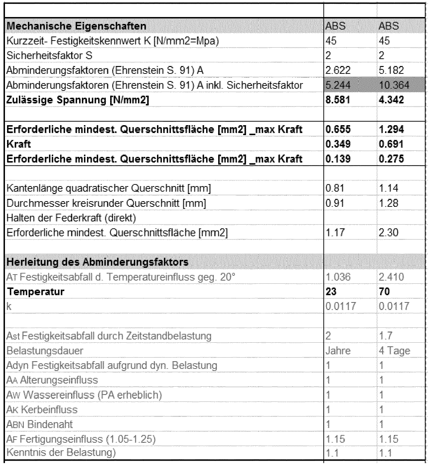
Eine Belastung von ABS während 96h bei 70°C bspw. resultiert in einem höheren Abminderungsfaktor inkl. Sicherheitsfaktoren von 10.4 als die Belastung bei 23°C während mehreren Jahren (Abminderungsfaktor inkl. Sicherheitsfaktoren von 5.2).A load of ABS during 96h at 70 ° C, for example, results in a higher reduction factor including safety factors of 10.4 than the load at 23 ° C for several years (reduction factor including safety factors of 5.2).
Berücksichtig man folglich eine Reduktion der zulässigen Spannung um den Abminderungsinkl. Sicherheitsfaktor von 10.4, resultiert ein Wert für die zulässige Spannung zur mechanischen Belastung eines ABS- Bauteils von 4.3MPa.Consider, therefore, a reduction of the allowable stress by the reduction index. Safety factor of 10.4, results in a value for the permissible stress for the mechanical load of an ABS component of 4.3MPa.
Um die Gesamtverformung resp. Dehnung abzuschätzen, welche eine gewisse Last, bei gegebener Belastungsdauer und Umgebungstemperatur, auf eine Struktur eines Kunststfoffbauteils bewirken kann, können isochrone Spannungsdehnungs- Diagramme od. Wertetabellen verwendet werden. Die Werte basieren auf Zugversuchen.To the total deformation resp. To estimate elongation, which can cause a certain load, for a given load duration and ambient temperature, on a structure of a Kunststfoffbauteils, isochronous stress-strain diagrams od. Tables can be used. The values are based on tensile tests.
Die folgende Tabelle weist Spannungsdehnungskennwerte eines ABS Kunststoffes bei 23°C für unterschiedliche Belastungszeiträume auf:
Die folgende Tabelle weist Spannungsdehnungskennwerte eines ABS Kunststoffes bei 60°C für unterschiedliche Belastungszeiträume auf:
Das Beispiel der ABS Dimensionierung hat für die Belastung während 96h bei 70° eine zulässige Spannung von 4.3 MPa ergeben.The example of ABS dimensioning has given a permissible stress of 4.3 MPa for the load during 96h at 70 °.
Aus den isochronen Spannungsdehnungs- Wertetabellen lässt sich nun abschätzen wie hoch die Gesamtverformung der Bauteil- Struktur beträgt sofern die Last für eine bestimmte Zeit bei einer bestimmten Temperatur beaufschlagt wird:It can now be estimated from the isochronous stress-strain value tables how high the total deformation of the component structure is, as long as the load is applied for a certain time at a certain temperature:
Elektrisch leitfähiger Kunststoff ist elektrisch leitfähig und vorzugsweise ein Thermoplast. Wird häufig für ESD-Kritische Bereiche (z.B. Verpackungen) eingesetzt.Electrically conductive plastic is electrically conductive and preferably a thermoplastic. Often used for ESD critical areas (e.g., packaging).
Bei elektrisch leitfähigen Polymeren wird zwischen intrinsisch leitendenden und solchen, die aufgrund der Füllstoffe leitfähig werden, unterschieden.In the case of electrically conductive polymers, a distinction is made between intrinsically conductive and those which become conductive on account of the fillers.
Das Material kann zum Beispiel sehr feinen Ruß oder Aluminiumflocken enthalten. Durch die Größe der Partikel des Füllmaterials, Leitrusspartikel sind im Nanobereich anzusiedeln, ist es homogen im ganzen Bauteil verteilt. Die Leifähigkeit des Kunststoffes ist somit nicht davon abhängig, ob ein Stück am Rand oder in der Mitte kontaktiert wird. Das ermöglicht es auch sehr kleine Teile oder Geometrien auszubilden, die als Schmelzstelle wirken können, ohne Randeinflüsse zu erhalten.The material may, for example, contain very fine soot or aluminum flakes. Due to the size of the particles of the filling material, Leitrusspartikel are to settle in the nano range, it is homogeneously distributed throughout the component. The Leifähigkeit of the plastic is thus not dependent on whether a piece is contacted at the edge or in the middle. This also makes it possible to form very small parts or geometries, which can act as a melting point, without obtaining edge influences.
Der Übergangswiderstand zwischen Kunststoffbauteil und Elektroden ist umso geringer, je inniger die Verbindung ist. Optimal ist eine möglichst große Kontaktfläche. Einen kleinen Übergangswiderstand erreicht man durch die Verbindung der Elektroden mit dem Kunststoff durch Verkleben, Verschweissen oder Verschrauben. Für den Übergangswiderstand spielt auch das Material und Oberflächenbeschaffenheit der Elektroden eine wichtige Rolle.The contact resistance between the plastic component and the electrodes is the lower, the more intimate the connection is. Optimal is the largest possible contact surface. A small contact resistance is achieved by connecting the electrodes to the plastic by gluing, welding or screwing. For the contact resistance also the material and surface condition of the electrodes plays an important role.
Ein Element aus elektrisch leitendem Kunststoff kann auf einen gewünschten elektrischen Wert dimensioniert werden: ![]()
- R: Widerstandswert des Elements[Ohm]
- R □: Spezifischer Widerstand[Ohm □]
- L: Abstand zwischen den Elektroden[m]
- B: Breite des Elements[m]
- R : resistance of the element [ ohm ]
- R □ : resistivity [ ohm □]
- L : distance between the electrodes [ m ]
- B : width of the element [ m ]
Das elektrisch leitfähige Material Pre-Elec PP1830 weist einen spezifischen Widerstand von 5 Ohm cm bei 25 °C auf. Unter Temperatureinwirkung verändert sich dieser Wert. Bei einer Temperatur von 80 °C beträgt er das Dreifache als bei 25 °C. Bei einer Temperatur von 140 °C weist er wieder denselben Wert wie bei 25 °C auf.The electrically conductive material Pre-Elec PP1830 has a resistivity of 5 ohm cm at 25 ° C. Under the influence of temperature, this value changes. At a temperature of 80 ° C it is three times that at 25 ° C. At a temperature of 140 ° C it has the same value as at 25 ° C again.
Der Widerstandswert verändert sich, die Temperatur ausgeblendet, nur wenig. Selbst wenn mit einem Gegenstand eingestochen wird, bleibt die Leitfähigkeit weitgehend erhalten. Eine verschweisste Kontaktierung bleibt stabil und ist auch nach dem Erkalten noch intakt.The resistance changes, the temperature disappears, but little. Even when an object is pierced, the conductivity is largely retained. A welded contact remains stable and is still intact even after cooling down.
Einer der Vorteile des elektrisch leitenden Kunststoffs ist, dass ein Bauteil gleichzeitig als Heizung und zu schmelzendes Element wirkt. Dies ermöglicht einen kompakteren Aufbau, zudem werden dadurch die Verluste durch Wärmestrahlung und Wärmeübergang reduziert. Weiter bietet der elektrisch leitende Kunststoff eine hohe Gestaltungsfreiheit bei der Geometrie und kann effizient durch Spritzguss hergestellt werden.One of the advantages of the electrically conductive plastic is that a component simultaneously acts as a heater and element to be melted. This allows a more compact construction, and in addition the losses due to heat radiation and heat transfer are thereby reduced. Furthermore, the electrically conductive plastic offers a high degree of freedom in geometry and can be produced efficiently by injection molding.
Idee: Das zu schmelzende Element wird mit einer metallischen Spule umgeben. Aufgrund der hohen Leitfähigkeit des Metalls wird ein Draht lang, wenn er einen gewünschten elektrischen Widerstandswert erreichen soll. Unteranderem sind folgende metallische Materialien grundsätzlich geeignet für eine solche Anwendung: Aluminium, Zink, Zinn, Kupfer und Wolfram.Idea: The element to be melted is surrounded by a metallic coil. Due to the high conductivity of the metal, a wire becomes long if it has a desired electrical To reach resistance value. Among others, the following metallic materials are basically suitable for such an application: aluminum, zinc, tin, copper and tungsten.
Die Vorteile dieser Variante ist, dass das Drahtmaterial gut verfügbar und vergleichsweise preiswert ist. Weiter kann die zu erweichende Stelle direkt mit dem Draht umwickelt werden, oder der Draht kann beim Kunststoffspritzgiessen direkt eingelegt werden. Dadurch ist der Abstand zwischen Wärmequelle und zu erwärmenden Querschnitt sehr klein und Toleranzen können aufgehoben werden.The advantages of this variant is that the wire material is readily available and comparatively inexpensive. Next, the point to be softened can be wrapped directly with the wire, or the wire can be inserted directly in plastic injection molding. As a result, the distance between the heat source and the cross section to be heated is very small and tolerances can be eliminated.
Der spezifische Widerstand des Materials sollte so gross sein, dass sich eine passende Länge des Drahts ergibt. Die Länge des Drahts sollte in der Grössenordnung von 10 mm sein. Für den Betrieb mit einem Akku sollte der Widerstandswert zwischen 10 bis 20 Ohm liegen. Mit diesen Werten kann eine praktikable Heizleistung erzeugt werden, um den Draht auf die gewünschte Temperatur zu erhitzen.
![]()
![]()
- R: Widerstandswert des Drahts [Ohm]
- ρ: Spezifischer Widerstand

- l: Länge des Drahts [m]
- A: Querschnitt des Drahts[mm2]
- R : resistance value of the wire [ ohm ]
- ρ : resistivity
- l : length of the wire [ m ]
- A : Cross section of the wire [ mm 2]
Die Energiequelle in der Patchpumpe kann idealerweise 0.5 Watt während mehreren Sekunden liefern. Dies hat Einfluss auf die Gestaltung und Auslegung der Wärmequelle. Das Heizelement resp. die Wärmequelle muss mit der zur Verfügung stehenden elektrischen Leistung das Medium erwärmen und zum wegweichen/wegfließen bringen.The energy source in the patch pump can ideally deliver 0.5 watts for several seconds. This affects the design and layout of the heat source. The heating element resp. The heat source must heat the medium with the available electrical power and make it move away.
Als Wärmequelle kommen verschiedene Medien infrage.As a source of heat, various media come into question.
In der Elektronik eingesetzte Widerstände für die Oberflächenmontage sind in unterschiedlich grossen Bauformen erhältlich. Sie sind sehr widerstandsfähig und der gleiche Widerstand kann während vielen Schmelzvorgängen verwendet werden. Bedingt durch ihre Bauart und Kontaktierung ist die Wärmeableitung auf die anschließenden Leiter relativ hoch. Ihr Vorteil ist, dass sie sehr temperaturresistent sind. Die Temperaturresistenz ist durch den Herstellprozess gegeben - die resistive Paste wird bei 850°C eingebrannt. Dadurch ist der Widerstand auch sehr robust gegenüber mechanischer Beschädigung. Zudem sind solche Widerstände Massenware, wodurch sie sehr preiswert sind.Resistors used in electronics for surface mounting are available in different sizes. They are very resistant and the same resistance can be used during many melting processes. Due to their design and contacting the heat dissipation is relatively high on the subsequent conductor. Their advantage is that they are very temperature resistant. The temperature resistance is given by the manufacturing process - the resistive paste is baked at 850 ° C. As a result, the resistance is also very robust against mechanical damage. In addition, such resistors are mass-produced, which makes them very inexpensive.
Nach dem Prinzip des SMD-Widerstand könnte eine spezifische Bauform des Substrat hergestellt werden. Diese wird an der gewünschten Stelle mit einer Widerstandsschicht ausgestattet. Der Vorteil dieser Variante liegt, neben der Hitzeresistenz, der Robustheit gegenüber mechanischer Beschädigung, vor allem in der geringeren Wärmekapazität und der Möglichkeit die Geometrie individuell zu gestalten, womit die Effizienz deutlich erhöht werden kann.According to the principle of SMD resistance, a specific design of the substrate could be produced. This is equipped at the desired location with a resistive layer. The advantage of this variant is, in addition to the heat resistance, the robustness to mechanical damage, especially in the lower heat capacity and the ability to design the geometry individually, so the efficiency can be significantly increased.
Die Technologie des Widerstandsdrucks auf Leiterplatten wird häufig in Bedienelementen wie Taster und Drehpotentiometer in Bedienelementen eingesetzt.The technology of resistance pressure on PCBs is often used in controls such as buttons and rotary potentiometer in controls.
Carbonlack kann für direkt auf Leiterplatten gedruckte Widerstände verwendet werden. Hierzu wird die Lücke zwischen zwei Leiterbahnen durch eine Fläche aus Carbon-Leitlack überdeckt. In diesem Bereich ist die Leiterplatte frei von Lötstopplack. Der Widerstand ist gleich dem spezifischen Flächenwiderstand [W (je square)], multipliziert mit dem Verhältnis von Abstand zu Breite des Carbon-Lacks:
- Es stehen Carbonpasten mit
einem Flächenwiderstand von 10 Ohm bis 1000 kOhm zur Verfügung. Unter Ausnutzung verschiedener Lack-Geometrien (z. B. Meander) können Widerstände von wenigen Ohm bis zu mehreren 10 kOhm erzeugt werden. Die Toleranz des Widerstands in der Endanwendung liegt ohne Laserabgleich bei ca. 30% undmit Laserabgleich bei 5 %. Die Schichtdicke der Paste beträgt 20 µm. Die minimale Breite der Strukturen z.B. der Meander beträgt 0.2 mm
- Carbon pastes with a surface resistance of 10 ohms to 1000 kOhms are available. Taking advantage of different paint geometries (eg Meander), resistors of a few ohms up to several 10 kOhm can be generated. The tolerance of the resistance in the final application is approx. 30% without laser adjustment and 5% with laser adjustment. The layer thickness of the paste is 20 μm. The minimum width of the structures, for example, the meander is 0.2 mm
Die Vorteile dieser Variante liegen in der sehr geringen Wärmekapazität, was zu einer sehr schnellen Erwärmung führt. Weiter kann die Form des Widerstandes sehr frei gewählt werden und die Herstellung ist sehr kostengünstig.The advantages of this variant are the very low heat capacity, which leads to a very rapid heating. Further, the shape of the resistor can be chosen very freely and the production is very cost-effective.
Bedruckung von fast beliebigen Substratmaterialien und Formen mit Widerstandspasten.
Es stehen verschiedene Widerstandspasten zur Auswahl.Printing almost any substrate materials and molds with resistor pastes.
There are different resistance pastes to choose from.
Die Vorteile liegen darin, dass ein Substrat gewählt werden kann, welches eine hohe Wärmeisolation und geringe Wärmekapazität aufweist. Ein weiterer Vorteil ist die Möglichkeit, die Heizfläche drei dimensional gestalten zu können und dadurch die Wärmekopplung zum schmelzbaren Element zu erhöhen. Die Technologie ermöglicht das Herstellen von sehr kleinen Strukturen, was die eine geringe Wärmekapazität ermöglicht.The advantages are that a substrate can be selected which has a high heat insulation and low heat capacity. Another advantage is the ability to make the heating surface three-dimensional and thereby increase the heat coupling to the fusible element. The technology makes it possible to produce very small structures, allowing for low heat capacity.
- 11
- Kanülengehäusecannula housing
- 1.11.1
- Sperr- oder (Rück-)Halteelement oder Auslöseelement InserterLocking or (re-) retaining element or triggering element inserter
- 1.1a1.1a
- Antriebsfläche oder SchrägeDrive surface or slope
- 1.21.2
- Reverser-Führung, Ablaufsteuerung, KanülengehäusefingerReverser guide, flow control, cannula housing finger
- 1.2a1.2a
- schmaler Entkoppelbereichnarrow decoupling area
- 1.2b1.2b
- breiter Koppelbereichwide coupling area
- 22
- Soft-Kanülen-HalterSoft cannula holder
- 2.12.1
- Hintergriff oder Auslöseelement Reverser, KoppelelementRear handle or release element Reverser, coupling element
- 2.22.2
- Halterung SoftkanüleHolder soft cannula
- 2.32.3
- Öffnung für Ablaufsteuerung und FührungOpening for flow control and guidance
- 2.42.4
- Anlagefläche, InsertionsfederanschlagContact surface, insertion spring stop
- 2.52.5
- Anlagefläche, Hart-Kanülen-Halter-AnschlagContact surface, hard cannula holder stop
- 33
- Hart-Kanülen-HalterRigid cannula holder
- 3.13.1
- Hintergriff Reverser oder GegenkoppelelementRear grip reverser or counter coupling element
- 3.23.2
- Halterung HartkanüleHolder hard cannula
- 44
- InsertionsfederInsertionsfeder
- 55
- Rückzugsfederreturn spring
- 66
- Kanülenführungcannula guide
- 6.16.1
- Kanülenführungcannula guide
- 77
- Softkanülesoft cannula
- 88th
- Hartkanüle, StahlkanüleHard cannula, steel cannula
- 8.18.1
- Kanülenschleifecannula loop
- 99
- Sicherung(selement) oder SchmelzsicherungFuse (selement) or fuse
- 9.19.1
- Verbindungselementconnecting element
- 9.2a, b9.2a, b
- Halterungholder
- 9.39.3
- Aufweichelement, SchmelzelementSoftening element, melting element
- 9.49.4
- Aufweichelement, SchmelzelementSoftening element, melting element
- 9.59.5
- Halteelement, Aufweichelement, SchmelzelementHolding element, softening element, melting element
- 9.69.6
- Aufweichelement, Schmelzelement, schmelzbares MediumSoftening element, melting element, meltable medium
- 1010
- Erwärmungs- oder HeizelementHeating or heating element
- 10a, b10a, b
- Ausfräsungcountersink
- 10c10c
- elektrischer Kontaktelectric contact
- 1111
- Pumpe, ReservoirPump, reservoir
- 1212
- Haftfläche (Patch Pumpe)Adhesive surface (patch pump)
- 1313
- Batteriebattery
- 1414
- Führung, HohlzylinderGuide, hollow cylinder
- 14a, b14a, b
- Abflussöffnungdrain opening
- 1515
- Stößeltappet
- 1616
- Foliefoil
- 1717
- Haftfläche oder Klebefläche; HalteelementAdhesive surface or adhesive surface; retaining element
- 1818
- Basiselementbase element
- 1919
- aufgeklebte Strukturglued structure
Claims (16)
Priority Applications (2)
| Application Number | Priority Date | Filing Date | Title |
|---|---|---|---|
| EP17209772.7A EP3501569A1 (en) | 2017-12-21 | 2017-12-21 | Cannula insertion mechanism |
| PCT/IB2018/059690 WO2019123075A1 (en) | 2017-12-21 | 2018-12-06 | Cannula insertion mechanism |
Applications Claiming Priority (1)
| Application Number | Priority Date | Filing Date | Title |
|---|---|---|---|
| EP17209772.7A EP3501569A1 (en) | 2017-12-21 | 2017-12-21 | Cannula insertion mechanism |
Publications (1)
| Publication Number | Publication Date |
|---|---|
| EP3501569A1 true EP3501569A1 (en) | 2019-06-26 |
Family
ID=60781959
Family Applications (1)
| Application Number | Title | Priority Date | Filing Date |
|---|---|---|---|
| EP17209772.7A Withdrawn EP3501569A1 (en) | 2017-12-21 | 2017-12-21 | Cannula insertion mechanism |
Country Status (2)
| Country | Link |
|---|---|
| EP (1) | EP3501569A1 (en) |
| WO (1) | WO2019123075A1 (en) |
Families Citing this family (1)
| Publication number | Priority date | Publication date | Assignee | Title |
|---|---|---|---|---|
| CN114618053A (en) * | 2020-12-10 | 2022-06-14 | 苏州恒瑞宏远医疗科技有限公司 | Automatic medicine feeding device |
Citations (3)
| Publication number | Priority date | Publication date | Assignee | Title |
|---|---|---|---|---|
| WO2013016376A2 (en) * | 2011-07-25 | 2013-01-31 | Preciflex Sa | Fluid dispenser |
| DE102011084593A1 (en) * | 2011-10-17 | 2013-04-18 | Robert Bosch Gmbh | Current separation device |
| US9220838B2 (en) | 2011-09-26 | 2015-12-29 | Terumo Kabushiki Kaisha | Puncture device |
-
2017
- 2017-12-21 EP EP17209772.7A patent/EP3501569A1/en not_active Withdrawn
-
2018
- 2018-12-06 WO PCT/IB2018/059690 patent/WO2019123075A1/en active Application Filing
Patent Citations (3)
| Publication number | Priority date | Publication date | Assignee | Title |
|---|---|---|---|---|
| WO2013016376A2 (en) * | 2011-07-25 | 2013-01-31 | Preciflex Sa | Fluid dispenser |
| US9220838B2 (en) | 2011-09-26 | 2015-12-29 | Terumo Kabushiki Kaisha | Puncture device |
| DE102011084593A1 (en) * | 2011-10-17 | 2013-04-18 | Robert Bosch Gmbh | Current separation device |
Also Published As
| Publication number | Publication date |
|---|---|
| WO2019123075A1 (en) | 2019-06-27 |
Similar Documents
| Publication | Publication Date | Title |
|---|---|---|
| EP3727526B1 (en) | Cannula insertion mechanism | |
| EP3863698A1 (en) | Piercing device for an administration device | |
| DE10342059B4 (en) | Delivery device with piercing and Ausschutinrichtung | |
| DE10342058B4 (en) | Administration device for an injectable product with a trigger safety device | |
| DE102010049876B4 (en) | Interconnected different materials | |
| EP1745855B1 (en) | Dispenser for dispensing, in particular spraying, a fluid from a container | |
| EP1866945B1 (en) | Passive triggering of a circuit breaker for electrical feeders of motor vehicles | |
| DE8390057U1 (en) | Connector with fusible material and its own temperature control | |
| EP2323717A1 (en) | Automatic injection device for administering a fixed dose | |
| WO2000017051A9 (en) | Holding and releasing mechanism with a shape memory actuator | |
| DE10116189A1 (en) | Exploding bridge | |
| EP3501569A1 (en) | Cannula insertion mechanism | |
| DE102018215879A1 (en) | Plug connection with redundancy and vehicle with such | |
| DE102011080314B4 (en) | Electric heater | |
| EP3501573A1 (en) | Cannula insertion mechanism | |
| DE102010040933A1 (en) | Method for thermal joining of two components and thermal bonding tape | |
| EP2731653B1 (en) | Injection device and method for producing same | |
| DE4103562A1 (en) | Injection needle destroying cabinet - melts inserted needle by electric current flowing between guiding contact and metal plate | |
| DE10340584B4 (en) | System for administering an injectable product | |
| US20240131276A1 (en) | Cannula insertion mechanism | |
| EP4119080A1 (en) | Plasma probe and method of mounting the electrode | |
| EP1254759B1 (en) | Nozzle for welding plastic webs or films | |
| EP1369890A1 (en) | Indicator striker device for high voltage fuse | |
| DE10108634C2 (en) | Electromechanical component | |
| WO2017071937A1 (en) | Data page, especially for a book-like document, and method for producing the same |
Legal Events
| Date | Code | Title | Description |
|---|---|---|---|
| PUAI | Public reference made under article 153(3) epc to a published international application that has entered the european phase |
Free format text: ORIGINAL CODE: 0009012 |
|
| AK | Designated contracting states |
Kind code of ref document: A1 Designated state(s): AL AT BE BG CH CY CZ DE DK EE ES FI FR GB GR HR HU IE IS IT LI LT LU LV MC MK MT NL NO PL PT RO RS SE SI SK SM TR |
|
| AX | Request for extension of the european patent |
Extension state: BA ME |
|
| 17P | Request for examination filed |
Effective date: 20200102 |
|
| RBV | Designated contracting states (corrected) |
Designated state(s): AL AT BE BG CH CY CZ DE DK EE ES FI FR GB GR HR HU IE IS IT LI LT LU LV MC MK MT NL NO PL PT RO RS SE SI SK SM TR |
|
| STAA | Information on the status of an ep patent application or granted ep patent |
Free format text: STATUS: THE APPLICATION IS DEEMED TO BE WITHDRAWN |
|
| 18D | Application deemed to be withdrawn |
Effective date: 20200103 |