EP4119080A1 - Plasma probe and method of mounting the electrode - Google Patents
Plasma probe and method of mounting the electrode Download PDFInfo
- Publication number
- EP4119080A1 EP4119080A1 EP21184980.7A EP21184980A EP4119080A1 EP 4119080 A1 EP4119080 A1 EP 4119080A1 EP 21184980 A EP21184980 A EP 21184980A EP 4119080 A1 EP4119080 A1 EP 4119080A1
- Authority
- EP
- European Patent Office
- Prior art keywords
- electrode
- conductor
- plasma probe
- distal end
- plastic
- Prior art date
- Legal status (The legal status is an assumption and is not a legal conclusion. Google has not performed a legal analysis and makes no representation as to the accuracy of the status listed.)
- Pending
Links
Images


Classifications
-
- A—HUMAN NECESSITIES
- A61—MEDICAL OR VETERINARY SCIENCE; HYGIENE
- A61B—DIAGNOSIS; SURGERY; IDENTIFICATION
- A61B18/00—Surgical instruments, devices or methods for transferring non-mechanical forms of energy to or from the body
- A61B18/04—Surgical instruments, devices or methods for transferring non-mechanical forms of energy to or from the body by heating
- A61B18/042—Surgical instruments, devices or methods for transferring non-mechanical forms of energy to or from the body by heating using additional gas becoming plasma
-
- A—HUMAN NECESSITIES
- A61—MEDICAL OR VETERINARY SCIENCE; HYGIENE
- A61B—DIAGNOSIS; SURGERY; IDENTIFICATION
- A61B18/00—Surgical instruments, devices or methods for transferring non-mechanical forms of energy to or from the body
- A61B18/04—Surgical instruments, devices or methods for transferring non-mechanical forms of energy to or from the body by heating
- A61B18/12—Surgical instruments, devices or methods for transferring non-mechanical forms of energy to or from the body by heating by passing a current through the tissue to be heated, e.g. high-frequency current
- A61B18/14—Probes or electrodes therefor
- A61B18/1477—Needle-like probes
-
- A—HUMAN NECESSITIES
- A61—MEDICAL OR VETERINARY SCIENCE; HYGIENE
- A61B—DIAGNOSIS; SURGERY; IDENTIFICATION
- A61B18/00—Surgical instruments, devices or methods for transferring non-mechanical forms of energy to or from the body
- A61B18/04—Surgical instruments, devices or methods for transferring non-mechanical forms of energy to or from the body by heating
- A61B18/12—Surgical instruments, devices or methods for transferring non-mechanical forms of energy to or from the body by heating by passing a current through the tissue to be heated, e.g. high-frequency current
- A61B18/14—Probes or electrodes therefor
- A61B18/1492—Probes or electrodes therefor having a flexible, catheter-like structure, e.g. for heart ablation
-
- A—HUMAN NECESSITIES
- A61—MEDICAL OR VETERINARY SCIENCE; HYGIENE
- A61B—DIAGNOSIS; SURGERY; IDENTIFICATION
- A61B17/00—Surgical instruments, devices or methods, e.g. tourniquets
- A61B2017/00526—Methods of manufacturing
-
- A—HUMAN NECESSITIES
- A61—MEDICAL OR VETERINARY SCIENCE; HYGIENE
- A61B—DIAGNOSIS; SURGERY; IDENTIFICATION
- A61B18/00—Surgical instruments, devices or methods for transferring non-mechanical forms of energy to or from the body
- A61B2018/00053—Mechanical features of the instrument of device
- A61B2018/00059—Material properties
- A61B2018/00071—Electrical conductivity
- A61B2018/00077—Electrical conductivity high, i.e. electrically conducting
-
- A—HUMAN NECESSITIES
- A61—MEDICAL OR VETERINARY SCIENCE; HYGIENE
- A61B—DIAGNOSIS; SURGERY; IDENTIFICATION
- A61B18/00—Surgical instruments, devices or methods for transferring non-mechanical forms of energy to or from the body
- A61B2018/00053—Mechanical features of the instrument of device
- A61B2018/00059—Material properties
- A61B2018/00071—Electrical conductivity
- A61B2018/00083—Electrical conductivity low, i.e. electrically insulating
-
- A—HUMAN NECESSITIES
- A61—MEDICAL OR VETERINARY SCIENCE; HYGIENE
- A61B—DIAGNOSIS; SURGERY; IDENTIFICATION
- A61B18/00—Surgical instruments, devices or methods for transferring non-mechanical forms of energy to or from the body
- A61B2018/00053—Mechanical features of the instrument of device
- A61B2018/00059—Material properties
- A61B2018/00089—Thermal conductivity
- A61B2018/00101—Thermal conductivity low, i.e. thermally insulating
-
- A—HUMAN NECESSITIES
- A61—MEDICAL OR VETERINARY SCIENCE; HYGIENE
- A61B—DIAGNOSIS; SURGERY; IDENTIFICATION
- A61B18/00—Surgical instruments, devices or methods for transferring non-mechanical forms of energy to or from the body
- A61B2018/00053—Mechanical features of the instrument of device
- A61B2018/00107—Coatings on the energy applicator
- A61B2018/00148—Coatings on the energy applicator with metal
-
- A—HUMAN NECESSITIES
- A61—MEDICAL OR VETERINARY SCIENCE; HYGIENE
- A61B—DIAGNOSIS; SURGERY; IDENTIFICATION
- A61B18/00—Surgical instruments, devices or methods for transferring non-mechanical forms of energy to or from the body
- A61B2018/00053—Mechanical features of the instrument of device
- A61B2018/00166—Multiple lumina
-
- A—HUMAN NECESSITIES
- A61—MEDICAL OR VETERINARY SCIENCE; HYGIENE
- A61B—DIAGNOSIS; SURGERY; IDENTIFICATION
- A61B18/00—Surgical instruments, devices or methods for transferring non-mechanical forms of energy to or from the body
- A61B2018/00053—Mechanical features of the instrument of device
- A61B2018/00184—Moving parts
- A61B2018/00196—Moving parts reciprocating lengthwise
-
- A—HUMAN NECESSITIES
- A61—MEDICAL OR VETERINARY SCIENCE; HYGIENE
- A61B—DIAGNOSIS; SURGERY; IDENTIFICATION
- A61B18/00—Surgical instruments, devices or methods for transferring non-mechanical forms of energy to or from the body
- A61B18/04—Surgical instruments, devices or methods for transferring non-mechanical forms of energy to or from the body by heating
- A61B18/12—Surgical instruments, devices or methods for transferring non-mechanical forms of energy to or from the body by heating by passing a current through the tissue to be heated, e.g. high-frequency current
- A61B18/14—Probes or electrodes therefor
- A61B2018/1405—Electrodes having a specific shape
- A61B2018/1425—Needle
-
- A—HUMAN NECESSITIES
- A61—MEDICAL OR VETERINARY SCIENCE; HYGIENE
- A61B—DIAGNOSIS; SURGERY; IDENTIFICATION
- A61B18/00—Surgical instruments, devices or methods for transferring non-mechanical forms of energy to or from the body
- A61B18/04—Surgical instruments, devices or methods for transferring non-mechanical forms of energy to or from the body by heating
- A61B18/12—Surgical instruments, devices or methods for transferring non-mechanical forms of energy to or from the body by heating by passing a current through the tissue to be heated, e.g. high-frequency current
- A61B18/14—Probes or electrodes therefor
- A61B2018/147—Electrodes transferring energy by capacitive coupling, i.e. with a dielectricum between electrode and target tissue
Definitions
- the subject matter of the invention is a plasma probe, in particular an argon plasma probe, and a method for mounting an electrode of this plasma probe.
- Electrosurgical instruments with electrodes that act directly on tissue are known.
- the WO 2017/076721 A1 a high-frequency tool with an electrode designed as a resection loop.
- the U-shaped electrode is inserted with its two ends in corresponding receptacles, to each of which an electrical lead wire leads.
- the electrode is crimped or welded to this lead wire, but in any case is mechanically firmly connected.
- a line insulation of the electrical supply line extends over the end of the electrode and insulates it from an outer sheath.
- an instrument for fallopian tube coagulation which has an attachment provided with a plurality of electrodes at its distal end. These are connected to a coaxial cable via a coaxial connector.
- This arrangement consisting of a supply line and a plug, can be freely moved axially in the working channel of an endoscope.
- plasma probes which essentially consist of a gas source that can be connected Tube exist, the distal end is open and is used to deliver a plasma jet.
- An electrode is arranged in the distal end of the tube and is typically held by means of an electrode holder, for example a metal plate extending diametrically through the lumen of the tube. The electrode continues as a lead wire proximally through the lumen of the tubing and is connectable to an electrical source to produce an electrical discharge at the distal end.
- Plasma probes constructed according to this principle are also available from DE 10 2017 127 976 A1 , the DE 100 30 111 B4 or the EP 3 769 707 A1 known.
- a plasma stream emanates from the electrode of the plasma probe, which is intended to hit the tissue to be treated.
- the electrode is located in the distal end of the tube, at least a portion of the heat energy generated also reaches the surrounding wall of the distal end of the tube.
- a ceramic sleeve can be arranged here, as is the case, for example, from the above-mentioned WO 2005/046495 A1 is known.
- the centric storage of the electrodes is taken over by the metal plate, which transfers heat to the hose and can lead to its destruction if it is used for a longer period of time. This in particular because the electrode must be firmly connected to the metal plate, so that there is a significant heat transfer from the electrode to the plate. This problem arises even more when the metal plate itself serves as an electrode, as for example in DE 100 30 111 B4 suggested.
- the plasma probe of the present invention includes a flexible tube made, for example, of a plastic material, which may have one or more lumens, each extending from its proximal end to its distal end.
- the lumen serves to conduct a suitable gas, preferably an inert gas such as argon, from the proximal end to the distal end.
- the lumen of the tube is open at the distal end so that the gas can flow out here.
- An electrical conductor is arranged in the tube, which preferably extends over the entire length of the tube from the proximal end to the distal end thereof and is connected to an electrode there.
- the electrical conductor is provided with a plastic sheathing at least at its distal end.
- the plastic sheathing can consist of the same plastic as the hose. But it is also possible to provide different plastics.
- the electrode is preferably a straight needle or rod-like electrode having a proximal end and a distal end.
- the electrode is hollow in whole or at least over part of its length, ie it has an inner channel which is open at both ends or closed at the distal end and which forms a cavity.
- the conductor extends with its distal end into this cavity with play.
- the electrode is thereby separated from the conductor and, at least at some embodiments of the invention, also carried by the plastic coating of the conductor. It is possible to arrange the electrode so that its proximal end extends into and is axially fixed by the plastic sheath of the conductor. When not in use, it can be fixed by friction between the plastic coating and the electrode. After the first use, the plastic sheathing can be melted onto the electrode and thus glued to it, so that there is a material connection between the proximal end of the electrode and the plastic sheathing.
- the conductor extends into the electrode with a loose fit.
- the conductor and the electrode Due to the slight ripple or bend in the conductor that is always present, or even simply because the conductor and the electrode are not completely aligned.
- the HF voltage applied to the conductor is so high that any gap between the conductor and the electrode is easily overcome by the current.
- there may be a slight flow of material at the contact points between the conductor and the electrode so that a bonded connection similar to a soldered or welded connection is formed.
- the electrode can be deformed somewhat radially inwards for fixation on the conductor, for example by squeezing or crimping. Such a deformation can be formed at the distal end of the electrode, at the proximal end of the electrode, or in between. The conductor then extends in distal direction at least beyond the deformed area.
- a plasma probe constructed according to this concept can be easily manufactured.
- the production comprises the following steps: - Provision of a tube having a proximal end and a distal end, between which at least one lumen is formed, wherein an electrical conductor is arranged in the tube, extending from the proximal end of the tube to whose distal end has a plastic coating, - optionally removing the plastic coating from a distal section of the conductor so that it is exposed, - providing an electrode which has at least one hollow end, - sliding the hollow end of the electrode onto the preferably freed from the plastic sheathing end of the conductor and, pushing the hollow end of the electrode into the plastic sheathing of the conductor.
- the electrode can thus be inserted into the plasma probe and fixed therein in a single assembly step by simply being pushed onto the preferably exposed end of the conductor and, if necessary, pushed into the intermediate space opening between the conductor and the plastic sheath. As a result of the expansion of the plastic sheathing that takes place in the process, it lies firmly against the electrode under pretension.
- the electrode is preferably made of a metal.
- it can be provided with a coating on its outside, in particular a coating made of a metal or a metal alloy.
- the metal of the coating preferably has a melting temperature which is lower than the melting temperature of the material from which the electrode is made.
- Silver or silver alloys are suitable as the coating metal.
- other metals in particular metals with a low tendency to oxidize and/or high electrical and/or thermal conductivity, can also be used.
- a particular advantage of the structure according to the invention lies in the thermal decoupling of the electrode from the hose. Even if the electrode becomes hot after long-term use, it cannot melt the outer tube due to heat conduction.
- the plasma probe according to the invention thus has a colder distal end than conventional probes, which enables the probe to have a longer service life. The influence of tissue from the heat emitted by the probe is also reduced.
- the plastic sheathing melts slightly during use and thus creates a firm material connection between the electrode and the conductor or its plastic sheathing.
- the concept according to the invention permits an exact, both axial and radial, alignment of the electrode. Even if the tube is deformed externally for a short time, it will not affect the positioning of the electrode.
- the lumen enclosed by the hose can be divided into two or more partial lumina running parallel to one another.
- the subdivision can extend over the entire length of the hose or only over a partial length.
- the division of the lumen into sub-lumina can be done by radially oriented walls or walls oriented obliquely to the radial direction, which connect the hose to the plastic sheathing.
- the walls can help to centrally store and hold the conductor in the hose.
- the hose can thus be produced in one operation, for example by plastic extrusion, together with the plastic sheathing of the conductor and the at least one connecting wall between the hose and the plastic sheathing. Only one plastic material is preferably used in this case.
- the plastic sheathing and the hose can be movably arranged in the hose, for example in the axial direction and/or in the radial direction.
- the distal end of the hose can be provided with a temperature-resistant sleeve, which is preferably electrically insulating and consists, for example, of ceramic to avoid direct contact between the plasma stream being formed and the hose made of plastic.
- the electrode which is only held at its proximal end, preferably extends in a cantilevered manner away from the conductor in the distal direction without protruding from the lumen of the tube. This prevents direct contact between the electrode and biological tissue.
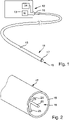
- a plasma probe 11 connected to a feeding device 12 is illustrated.
- the device 12 provides the operating media and electrical power required to operate the plasma probe 11 .
- the device 12 contains a high-frequency generator 13 and a gas source 14. This includes, for example, pressure regulators and valves via which a gas flow taken from a gas cylinder, for example an argon flow, can be directed to the plasma probe 11 in a controlled manner.
- the plasma probe 11 has a tube 15 which extends from a proximal end 16 to a distal end 17 .
- the end face 18 of the distal end 17 of the hose 15 surrounds a plasma orifice 19 which, in use, emits a plasma jet.
- the terms end, distal end and proximal end always refer to end regions.
- Electrode 20 which is electrically connected to the HF generator 13 is also arranged in the plasma outflow opening 19 .
- An example is used for this purpose Figure 3 and 4 conductor 21 can be seen which extends through the entire length of tube 15 from its proximal end 16 to its distal end 17.
- the electrode 20 can be made of a temperature-resistant material, for example stainless steel.
- it can be provided with a coating, in particular a coating, whose melting point is preferably lower than the melting point of the electrode 20.
- the coating can consist of silver or a silver alloy.
- the conductor 21 can, for example, consist of a monofilament wire, for example a stainless steel wire or also be formed by a wire made of a different material.
- the conductor 21 is provided with a plastic sheathing 22 at least over part of its length, which preferably surrounds the conductor 21 over its entire circumference (360°).
- the plastic sheathing 22 can extend over the entire length of the conductor up to its distal end 23 .
- the distal end 23 of the conductor 21 may itself be exposed, ie free of plastic coating.
- the exposed portion can be one or more millimeters long.
- the plastic casing 22 extends, starting from the distal end 23, at least a few centimeters in the proximal direction. However, it can also take up the entire length of the conductor 21 .
- the plastic casing 22 is connected to the hose 15 via at least one, preferably a plurality of walls 24, 25, 26, as shown in FIG figure 3 emerges. These subdivide a lumen 27 enclosed by the hose 15 into two or more, here three, partial lumina 28, 29, 30.
- the walls 24, 25, 26 can, as in figure 3 apparent, run inclined against the radial direction, for example in the spiral direction, or be arranged in some other way. In addition, the walls can be either flat or curved, as shown.
- the electrode 20 can, as in figure 4 illustrated, be formed by a metal tube. This has a central channel or cavity into which the distal end 23 of the conductor 21 extends. The inner diameter of this channel or cavity is preferably slightly larger than the outer diameter of the conductor 21, so that there is a loose fit between the two.
- the electrode 20 hollow-cylindrical and open at its distal end 31 .
- the proximal end 32 of the electrode 20 has been slid onto the conductor 21 to such an extent that it has been slid between the plastic sheathing 22 and the conductor 21 .
- figure 4 shows that the plastic sheathing 22 is locally detached from the conductor 21 and widened, whereby it initially secures the electrode 20 at least by friction.
- the distal end 23 of the conductor 21 rests loosely in the channel or cavity of the electrode 20 and initially rests on the electrode 20 at certain points.
- the connection between the conductor 21 and the electrode 20 is preferably loose in the axial direction, ie it does not transmit tensile forces.
- this can have an end surface at its distal end that is oriented obliquely to its longitudinal direction.
- the tube-shaped electrode 20 can be cut obliquely to its axis at its distal end, like the distal end of the cannula of a syringe.
- the lead can extend through the electrode 20 and protrude beyond the distal end of the electrode 20. This can contribute to improving the ignitability.
- the plasma probe 11 described so far can be manufactured by first providing the hose 15 with the conductor 21 arranged therein.
- the tube 15 with the conductor 21 can be produced like a cable by plastic extrusion.
- the length desired for the plasma probe 11 is cut from the material thus provided and the conductor 21 at its end distal end 23 initially exposed.
- the corresponding material of the plastic casing 22 and the walls 24 to 26 is removed.
- the distal end 23 of the conductor 21 is exposed.
- the electrode 20 is pushed onto the exposed distal end 23 of the conductor 21 and pushed into the plastic sheathing 22 . How out figure 4 can be seen, the electrode 20 pushes the plastic sheathing 22 radially outwards and is thereby itself pinched. The electrode 20 is now held by friction. The distal end 23 of the conductor 21 rests loosely on the inner wall of the electrode 20 at certain points. The electrode 20 is preferably pushed in so far that, seen from the outside, it stands behind the distal end face 18 of the hose 15, ie is offset proximally from this end face 18. The plasma probe 11 can now be used.
- the proximal end of the conductor 21 is electrically connected to the HF generator 13 .
- the proximal end of lumen 27 is connected to gas source 14 .
- the lumen 27 is supplied with gas, for example argon, or another inert gas, so that a gas flow flowing in the distal direction is created in the lumen 27 .
- the HF generator 13 now supplies the electrodes 20 with HF voltage of typically several 100 volts in relation to a neutral potential which is applied to the patient to be treated via a neutral electrode (not shown).
- a so-called spark is now produced at the electrode 20, with which the outflowing gas is ionized, so that a plasma jet forms.
- the current flows from the conductor 21 via the contact points between the distal end 23 and the electrode 20 to the electrode 20 and from there via the ionized gas to the patient.
- the flow of current can cause the conductor 21 to be soldered or welded to the electrode 20 at certain points, and thus a mechanical connection.
- the electrode 20 heats up considerably, as a result of which the plastic casing 22 can melt or melt in the area covering the electrode 20 . This creates a material connection between the casing 22 and the electrode 20 and/or between the conductor 21 and the electrode 20.
- each of the walls 24, 25, 26 can be dispensed with.
- the conductor 21 lies loosely with its sheathing 22 in the lumen 27 and can be moved axially and/or radially therein.
- the electrode 20 with a closed end 33 which forms the distal end of the electrode 20 .
- the above statements apply accordingly.
- connection between the electrode 20 and the conductor 21 may be solid wire as in the above embodiments. However, it can be substituted in this embodiment and also in the above-described embodiments Figure 3 and 4 a stranded wire can be used instead of a solid wire.
- the plasma probe after figure 6 can be dispensed with in the manufacture of an exposure of the distal end 22 of the conductor 21, ie the removal of the plastic sheathing 22 in this area. While the head 21 or its distal end 23 in the embodiments Figure 1 to 4 that guides the electrode 20 into the plastic sheath 22 upon insertion, such a guide is in the embodiment of FIG figure 6 not mandatory.
- the electrode 20 ′ which is preferably sharpened at its proximal end, is simply pierced into the plastic sheath 22 in the vicinity of the conductor 21 .
- the distal end 17 of the hose 15 can be formed by a temperature-resistant sleeve 34 made of ceramic, for example. this is in figure 6 illustrated by way of example for all other embodiments.
- the sleeve 34 can be connected to the hose 15 via a conical seat 35 .
- figure 7 Illustrates an embodiment of the plasma probe 11 in which the electrode 20 is only connected to the distal end 23 of the conductor 21 freed from the plastic sheathing 22 .
- the electrode 20 can be deformed by radial deformation, for example crimping or the like, be held captively on the end 23 of the conductor 21 .
- a plasma probe 11 is described purely by way of example, in which the conductor 21 and its plastic sheathing 22 and the electrode 20 are not firmly connected to the hose 15 .
- the construction principle with the electrode 20 secured only on the conductor 21 can also be implemented on any of the other plasma probes 11 described above.
- electrode 20 can also be used in probes in which there is no connection between the hose 15 and the plastic sheath 22.
- the conductor 21 with the plastic sheathing 22 can be inserted into the tube 15 as a single-core cable.
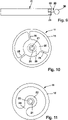
- the sleeve 34 located at the distal end 17 may have three or more inwardly pointing lugs 36, 37 or other structure permitting radial mobility of the electrode 20 or the conductor 21 is limited.
- the lugs 36, 37 are therefore suitable for bringing about a sufficient centering of the electrode 20. If the electrode 20 is mechanically connected to the conductor 21, for example by radial pinching as in figure 7 shown, the plastic casing 22 can also be dispensed with entirely. This applies to all embodiments.
- FIG 12 illustrates a further modification of the invention applicable to all of the plasma probes 11 described herein.
- the electrode 20 consists of a first sleeve 20a, which sits on the distal end 23 of the conductor 21 and is inserted into the plastic sheath 22 is.
- a second sleeve 20b sits on this sleeve 20a, which is welded or crimped to the sleeve 20a, for example, or simply sits on it with a friction fit.
- the two sleeves 20a, 20b are preferably made of different materials or material combinations.
- the hollow-cylindrical sleeve 20b can be silver-plated on its outer surface, as a result of which the plasma discharge is concentrated on the distal end thereof and the heat input into this sleeve 20b is minimized.
- the sleeve 20a on the other hand, can be made of uncoated stainless steel with poor thermal conductivity, so that the heat input into the plastic casing 22 is minimized. Regardless of the choice of material, a distance between the sleeve 20b and the plastic casing 22 can reduce the heat input into the plastic.
- the sleeve 20a and the joint between the sleeves 20a and 20b represents a thermal barrier between the part of the electrode 20 exposed to the discharge and the rest of the plasma probe 11. This increases the stability of the electrode 20 and the entire plasma probe 11 on the one hand due to the increase in the Electrode surface and on the other hand due to the reduction of the emanating from the electrode 20 heat flow.
- the electrode 20, 20' does not protrude beyond the distal end face 18 of the tube 15.
- the electrode 20, which can be connected to the conductor 21 in any of the ways described above, then protrudes beyond the end face 18 in distal direction and can carry an insulator body 38, for example made of ceramic or a temperature-resistant plastic.
- the insulator body 38 can have a spherical, mushroom-shaped or other shape and is carried by the electrode 20 .
- the walls 24, 25, 26 like it figure 10 shows, are arranged radially.
- the conductor 21 can also initially be surrounded by an insulation 39 which is embedded in the plastic sheathing 22 .
- the number of walls or other connections between the plastic casing 22 and the tube 15 can be defined differently from the previously described embodiments, such as figure 11 indicates. Only a single connecting wall 24 is provided there between the hose 15 and the plastic sheathing 22 .
- a plasma probe 11 according to the invention has a tube with a conductor arranged therein, which carries an electrode 20 at least at its distal end.
- the electrode 20 is either secured directly onto the conductor 21 or the conductor 21 is provided at least at its distal end with a plastic sheath 22 by which the electrode 20 is held.
- the electrode 20 can be inserted between the conductor 21 and the plastic sheath 22 and thereby clamped. After the initial start-up, the plastic casing 22 can be fused to the electrode 20 .
- the head 21 is but with play in a channel or a cavity of the electrode 20, whereby even with punctiform contact between the conductor 21 and the electrode 20 due to the otherwise existing gap between the two, the heat transfer from of the electrode 20 to the conductor 21 is impeded and thus the heat input into the plasma probe 11 is limited.
- This benefits the service life of the plasma probe 11 and at the same time reduces its outside temperature and thus its tendency to stick to the tissue. This reduces the risk of unwanted perforation of sensitive or thin tissue layers.
- the concept according to the invention enables the roundness of the probe to be maintained over the long term.
Abstract
Eine erfindungsgemäße Plasmasonde (11) weist einen Schlauch mit einem darin angeordneten Leiter auf, der zumindest an seinem distalen Ende eine Elektrode (20) trägt. Die Elektrode (20) ist entweder direkt auf den Leiter (21) gesichert oder der Leiter (21) ist zumindest an seinem distalen Ende mit einer Kunststoffummantelung versehen, von der die Elektrode (20) gehalten ist. Die Elektrode (20) kann zwischen dem Leiter (21) und die Kunststoffummantelung (22) eingeschoben und dadurch eingeklemmt sein. Nach Erstinbetriebnahme kann die Kunststoffummantelung (22) mit der Elektrode (20) verschmolzen sein. In jedem Fall liegt der Leiter (21) jedoch mit Spiel in einem Kanal oder einem Hohlraum der Elektrode (20), wodurch auch bei punktueller Berührung zwischen dem Leiter (21) und der Elektrode (20) infolge des sonst zwischen beiden vorhandenen Spalts die Wärmeübertragung von der Elektrode (20) auf den Leiter (21) behindert und somit der Wärmeeintrag in die Plasmasonde (11) begrenzt wird. Dies kommt der Lebensdauer der Plasmasonde (11) zugute und senkt zugleich deren Außentemperatur und damit deren Klebeneigung am Gewebe.A plasma probe (11) according to the invention has a tube with a conductor arranged in it, which carries an electrode (20) at least at its distal end. The electrode (20) is either secured directly onto the conductor (21) or the conductor (21) is provided with a plastic sheath at least at its distal end, by which the electrode (20) is held. The electrode (20) can be inserted between the conductor (21) and the plastic sheathing (22) and thereby clamped. After initial start-up, the plastic casing (22) can be fused to the electrode (20). In any case, however, the conductor (21) lies with play in a channel or a cavity in the electrode (20), which means that heat can be transferred even if there is contact between the conductor (21) and the electrode (20) due to the gap that otherwise exists between the two from the electrode (20) to the conductor (21) and thus the heat input into the plasma probe (11) is limited. This benefits the service life of the plasma probe (11) and at the same time reduces its outside temperature and thus its tendency to stick to the tissue.
Description
Gegenstand der Erfindung ist eine Plasmasonde, insbesondere eine Argon-Plasmasonde, sowie ein Verfahren zur Montage einer Elektrode dieser Plasmasonde.The subject matter of the invention is a plasma probe, in particular an argon plasma probe, and a method for mounting an electrode of this plasma probe.
Elektrochirurgische Instrumente mit Elektroden, die direkt auf ein Gewebe einwirken, sind bekannt. Beispielsweise offenbart die
Aus der
Des Weiteren existieren Plasmasonden, die im Wesentlichen aus einem an eine Gasquelle anschließbaren Schlauch bestehen, dessen distales Ende offen ist und zur Abgabe eines Plasmastrahls dient. In dem distalen Ende des Schlauchs ist eine Elektrode angeordnet, die typischerweise mittels eines Elektrodenhalters, beispielsweise eines sich diametral durch das Lumen des Schlauchs erstreckendes Metallplättchens, gehalten ist. Die Elektrode setzt sich als Leitungsdraht in proximaler Richtung durch das Lumen des Schlauchs fort und ist an eine elektrische Quelle anschließbar, um am distalen Ende eine elektrische Entladung hervorzurufen. Nach diesem Prinzip aufgebaute Plasmasonden sind außerdem aus der
Von der Elektrode der Plasmasonde geht ein Plasmastrom aus, der das zu behandelnde Gewebe treffen soll. Weil die Elektrode in dem distalen Ende des Schlauchs angeordnet ist, gelangt aber mindestens ein Teil der erzeugten Wärmeenergie auch auf die umgebende Wandung des distalen Endes des Schlauchs. Zum Schutz desselben kann hier eine Keramikhülse angeordnet werden, wie es beispielsweise aus der oben genannten
Hiervon ausgehend, ist es Aufgabe der Erfindung, ein Konzept anzugeben, mit dem sich eine langzeitstabile Plasmasonde auf einfache Weise bereitstellen lässt. Dabei soll besonderes Augenmerk auf die Montage der Elektrode gelegt werden.Proceeding from this, it is the object of the invention to specify a concept with which a long-term stable plasma probe can be provided in a simple manner. Included special attention should be paid to the assembly of the electrode.
Diese Aufgabe wird mit der Plasmasonde nach Anspruch 1 sowie mit dem Verfahren nach Anspruch 15 gelöst:This object is achieved with the plasma probe according to claim 1 and with the method according to claim 15:
Die erfindungsgemäße Plasmasonde weist einen zum Beispiel aus einem Kunststoffmaterial bestehenden flexiblen Schlauch auf, der ein Lumen oder mehrere Lumina aufweisen kann, die sich jeweils von seinem proximalen Ende bis zu seinem distalen Ende erstrecken. Das Lumen dient dazu, ein geeignetes Gas, vorzugsweise ein Inertgas, beispielsweise Argon, von dem proximalen Ende zu dem distalen Ende zu leiten. Das Lumen des Schlauchs ist an dem distalen Ende offen, sodass das Gas hier ausströmen kann.The plasma probe of the present invention includes a flexible tube made, for example, of a plastic material, which may have one or more lumens, each extending from its proximal end to its distal end. The lumen serves to conduct a suitable gas, preferably an inert gas such as argon, from the proximal end to the distal end. The lumen of the tube is open at the distal end so that the gas can flow out here.
In dem Schlauch ist ein elektrischer Leiter angeordnet, der sich vorzugsweise über die gesamte Länge des Schlauchs von dem proximalen Ende bis zu dem distalen Ende desselben erstreckt und dort an eine Elektrode angeschlossen ist. Der elektrische Leiter ist zumindest an seinem distalen Ende mit einer Kunststoffummantelung versehen. Die Kunststoffummantelung kann aus dem gleichen Kunststoff bestehen wie der Schlauch. Es ist aber auch möglich, unterschiedliche Kunststoffe vorzusehen.An electrical conductor is arranged in the tube, which preferably extends over the entire length of the tube from the proximal end to the distal end thereof and is connected to an electrode there. The electrical conductor is provided with a plastic sheathing at least at its distal end. The plastic sheathing can consist of the same plastic as the hose. But it is also possible to provide different plastics.
Die Elektrode ist vorzugsweise eine gerade ausgebildete nadel- oder stabartige Elektrode, die ein proximales und ein distales Ende aufweist. Die Elektrode ist insgesamt oder wenigstens über einen Teil ihrer Länge hohl ausgebildet, d.h. sie weist einen inneren, an beiden Enden offenen oder am distalen Ende geschlossenen Kanal auf, der einen Hohlraum bildet. Der Leiter erstreckt sich mit seinem distalen Ende mit Spiel in diesen Hohlraum hinein. Die Elektrode wird dadurch von dem Leiter und, zumindest bei einigen Ausführungsformen der Erfindung, auch von der Kunststoffummantelung des Leiters getragen. Es ist möglich, die Elektrode so anzuordnen, dass sich ihr proximales Ende in die Kunststoffummantelung des Leiters erstreckt und von dieser axial fixiert ist. In ungebrauchtem Zustand kann die Fixierung durch Reibschluss zwischen der Kunststoffummantelung und der Elektrode erfolgen. Nach erstem Einsatz kann die Kunststoffummantelung an die Elektrode angeschmolzen und dadurch mit dieser verklebt sein, sodass eine stoffschlüssige Verbindung zwischen dem proximalen Ende der Elektrode und der Kunststoffummantelung gegeben ist.The electrode is preferably a straight needle or rod-like electrode having a proximal end and a distal end. The electrode is hollow in whole or at least over part of its length, ie it has an inner channel which is open at both ends or closed at the distal end and which forms a cavity. The conductor extends with its distal end into this cavity with play. The electrode is thereby separated from the conductor and, at least at some embodiments of the invention, also carried by the plastic coating of the conductor. It is possible to arrange the electrode so that its proximal end extends into and is axially fixed by the plastic sheath of the conductor. When not in use, it can be fixed by friction between the plastic coating and the electrode. After the first use, the plastic sheathing can be melted onto the electrode and thus glued to it, so that there is a material connection between the proximal end of the electrode and the plastic sheathing.
Vorzugsweise erstreckt sich der Leiter mit Spielpassung in die Elektrode. Durch die immer gegebene leichte Welligkeit oder Biegung des Leiters oder auch nur aufgrund der nicht vollständigen Fluchtung zwischen dem Leiter und der Elektrode ist immer ein elektrischer Kontakt zwischen dem Leiter und der Elektrode gegeben. Außerdem ist die an dem Leiter anliegende HF-Spannung so hoch, dass ein etwaiger Spalt zwischen dem Leiter und der Elektrode vom Strom ohne weiteres überwunden wird. Nach erstem Einsatz kann es an Kontaktstellen zwischen dem Leiter und der Elektrode zu einem geringfügigem Materialfluss kommen, sodass sich eine stoffschlüssige Verbindung ähnlich einer Löt- oder Schweißverbindung ausbildet.Preferably, the conductor extends into the electrode with a loose fit. There is always electrical contact between the conductor and the electrode due to the slight ripple or bend in the conductor that is always present, or even simply because the conductor and the electrode are not completely aligned. In addition, the HF voltage applied to the conductor is so high that any gap between the conductor and the electrode is easily overcome by the current. After the first use, there may be a slight flow of material at the contact points between the conductor and the electrode, so that a bonded connection similar to a soldered or welded connection is formed.
Unabhängig davon, ob sich die Elektrode in die Kunststoffummantelung hinein erstreckt oder nicht, kann die Elektrode zur Fixierung auf den Leiter etwas radial nach innen zu verformt sein, beispielsweise durch Quetschen oder zu Crimpen. Eine solche Verformung kann am distalen Ende der Elektrode, am proximalen Ende der Elektrode oder dazwischen ausgebildet sein. Der Leiter erstreckt sich dann in distaler Richtung wenigstens bis über den verformten Bereich hinaus.Irrespective of whether the electrode extends into the plastic sheath or not, the electrode can be deformed somewhat radially inwards for fixation on the conductor, for example by squeezing or crimping. Such a deformation can be formed at the distal end of the electrode, at the proximal end of the electrode, or in between. The conductor then extends in distal direction at least beyond the deformed area.
Eine nach diesem Konzept aufgebaute Plasmasonde lässt sich einfach herstellen. Die Herstellung umfasst folgende Schritte: - Bereitstellung eines Schlauchs, der ein proximales Ende und ein distales Ende aufweist, zwischen denen wenigstens ein Lumen ausgebildet ist, wobei einem in dem Schlauch ein elektrischer Leiter angeordnet ist, der sich von dem proximalen Ende des Schlauchs bis zu dessen distalen Ende erstreckt, der eine Kunststoffummantelung aufweist, - optional Entfernen der Kunststoffummantelung von einem distalen Abschnitt des Leiter, so dass dieser frei liegt, - Bereitstellen einer Elektrode, die wenigstens ein hohl ausgebildetes Ende aufweist, - Aufschieben des hohlen Endes der Elektrode auf das vorzugsweise von der Kunststoffummantelung befreite Ende des Leiters und, Einschieben des hohlen Endes der Elektrode in die Kunststoffummantelung des Leiters. Die Elektrode kann somit in einem einzigen Montageschritt in die Plasmasonde eingesetzt und darin fixiert werden, indem sie lediglich auf das vorzugsweise freiliegende Ende des Leiters aufgesteckt und gegebenenfalls in den zwischen dem Leiter und der Kunststoffummantelung sich öffnenden Zwischenraum eingeschoben wird. Durch das dabei erfolgende Aufweiten der Kunststoffummantelung liegt diese unter Vorspannung fest an der Elektrode an.A plasma probe constructed according to this concept can be easily manufactured. The production comprises the following steps: - Provision of a tube having a proximal end and a distal end, between which at least one lumen is formed, wherein an electrical conductor is arranged in the tube, extending from the proximal end of the tube to whose distal end has a plastic coating, - optionally removing the plastic coating from a distal section of the conductor so that it is exposed, - providing an electrode which has at least one hollow end, - sliding the hollow end of the electrode onto the preferably freed from the plastic sheathing end of the conductor and, pushing the hollow end of the electrode into the plastic sheathing of the conductor. The electrode can thus be inserted into the plasma probe and fixed therein in a single assembly step by simply being pushed onto the preferably exposed end of the conductor and, if necessary, pushed into the intermediate space opening between the conductor and the plastic sheath. As a result of the expansion of the plastic sheathing that takes place in the process, it lies firmly against the electrode under pretension.
Die Elektrode besteht vorzugsweise aus einem Metall. Sie kann insbesondere an ihrer Außenseite mit einer Beschichtung versehen sein, insbesondere einer Beschichtung aus einem Metall oder einer Metall-Legierung. Vorzugsweise weist das Metall der Beschichtung eine Schmelztemperatur auf, die niedriger ist, als die Schmelztemperatur des Materials, aus dem die Elektrode besteht. Als Beschichtungsmetall eignen sich Silber oder Silberlegierungen. Es können aber auch andere Metalle, insbesondere Metalle mit niedriger Oxdidationsneigung und/oder hoher elektrischer und/oder thermischer Leitfähigkeit zur Anwendung kommen.The electrode is preferably made of a metal. In particular, it can be provided with a coating on its outside, in particular a coating made of a metal or a metal alloy. The metal of the coating preferably has a melting temperature which is lower than the melting temperature of the material from which the electrode is made. Silver or silver alloys are suitable as the coating metal. However, other metals, in particular metals with a low tendency to oxidize and/or high electrical and/or thermal conductivity, can also be used.
Ein besonderer Vorzug der erfindungsgemäßen Struktur liegt in der thermischen Entkopplung der Elektrode von dem Schlauch. Auch wenn die Elektrode nach längerem Einsatz heiß wird, kann sie den äußeren Schlauch nicht infolge von Wärmeleitung aufschmelzen. Die erfindungsgemäße Plasmasonde weist somit ein gegenüber herkömmlichen Sonden kälteres distales Ende auf, eine höhere Standzeit der Sonde ermöglicht. Auch wird die Beeinflussung von Gewebe durch von der seonde ausgehende Wärme gemindert. Zudem wird an der flächigen Verbindungsstelle zwischen dem proximalen Ende der Elektrode und der Kunststoffummantelung des Leiters beim Einsatz eine geringfügige Aufschmelzung der Kunststoffummantelung und dadurch eine feste stoffschlüssige Verbindung zwischen der Elektrode und dem Leiter bzw. seiner Kunststoffummantelung hergestellt.A particular advantage of the structure according to the invention lies in the thermal decoupling of the electrode from the hose. Even if the electrode becomes hot after long-term use, it cannot melt the outer tube due to heat conduction. The plasma probe according to the invention thus has a colder distal end than conventional probes, which enables the probe to have a longer service life. The influence of tissue from the heat emitted by the probe is also reduced. In addition, at the flat connection point between the proximal end of the electrode and the plastic sheathing of the conductor, the plastic sheathing melts slightly during use and thus creates a firm material connection between the electrode and the conductor or its plastic sheathing.
Weiter gestattet das erfindungsgemäße Konzept eine exakte sowohl axiale als auch radiale Ausrichtung der Elektrode. Selbst wenn der Schlauch kurzzeitig äußerlich verformt wird, wird dadurch die Positionierung der Elektrode nicht beeinträchtigt.Furthermore, the concept according to the invention permits an exact, both axial and radial, alignment of the electrode. Even if the tube is deformed externally for a short time, it will not affect the positioning of the electrode.
Das von dem Schlauch umschlossene Lumen kann in zwei oder mehrere zueinander parallel verlaufende Teillumina unterteilt sein. Die Unterteilung kann sich über die gesamte Länge des Schlauchs oder lediglich über eine Teillänge erstrecken. Die Unterteilung des Lumens in Teillumina kann durch radial ausgerichtete oder schräg zur Radialrichtung ausgerichtete Wände erfolgen, die den Schlauch mit der Kunststoffummantelung verbinden. Die Wände können dazu beitragen, den Leiter in dem Schlauch zentral zu lagern und zu halten. Der Schlauch kann somit mitsamt der Kunststoffummantelung des Leiters und der mindestens einen Verbindungswand zwischen dem Schlauch und der Kunststoffummantelung in einem Arbeitsgang, zum Beispiel durch Kunststoffextrusion, hergestellt werden. Vorzugsweise wird dabei nur ein Kunststoffmaterial verwendet. Es ist aber auch möglich, für den Schlauch und die Kunststoffummantelung unterschiedliche Kunststoffe zu verwenden und die Sonde durch Koextrusion zu erzeugen. Es ist zudem auch möglich, die Kunststoffummantelung und den Schlauch als voneinander unabhängige Elemente aus gleichen oder unterschiedlichen Kunststoffmaterialien bereitzustellen. Der Leiter mit seiner Kunststoffummantelung kann in dem Schlauch beweglich, beispielsweise in Axialrichtung und/oder in Radialrichtung beweglich angeordnet sein.The lumen enclosed by the hose can be divided into two or more partial lumina running parallel to one another. The subdivision can extend over the entire length of the hose or only over a partial length. The division of the lumen into sub-lumina can be done by radially oriented walls or walls oriented obliquely to the radial direction, which connect the hose to the plastic sheathing. The walls can help to centrally store and hold the conductor in the hose. The hose can thus be produced in one operation, for example by plastic extrusion, together with the plastic sheathing of the conductor and the at least one connecting wall between the hose and the plastic sheathing. Only one plastic material is preferably used in this case. However, it is also possible to use different plastics for the hose and the plastic sheathing and to produce the probe by coextrusion. In addition, it is also possible to provide the plastic sheathing and the hose as mutually independent elements made of the same or different plastic materials. The conductor with its plastic sheathing can be movably arranged in the hose, for example in the axial direction and/or in the radial direction.
Bei allen diesen Ausführungsformen existiert keine metallische Verbindung zwischen dem Leiter oder der Elektrode einerseits und dem Schlauch andererseits. Falls eine stoffliche Verbindung zwischen der Kunststoffummantelung und dem Schlauch existiert, ist diese Verbindung vorzugsweise frei von Metallelementen oder anderen gut wärmeleitenden Elementen. Auf diese Weise wird die Wärmeleitung zwischen dem der Elektrode und dem Schlauch minimiert. Ergänzend kann das distale Ende des Schlauchs mit einer vorzugsweise elektrisch isolierenden, beispielsweise aus Keramik bestehenden temperaturfesten Hülse versehen sein, um einen direkten Kontakt zwischen dem sich ausbildenden Plasmastrom und dem aus Kunststoff bestehend Schlauch zu vermeiden.In all of these embodiments there is no metallic connection between the conductor or the electrode on the one hand and the hose on the other hand. If there is a material connection between the plastic sheathing and the hose, this connection is preferably free of metal elements or other elements with good thermal conductivity. This minimizes heat conduction between the electrode and the tubing. In addition, the distal end of the hose can be provided with a temperature-resistant sleeve, which is preferably electrically insulating and consists, for example, of ceramic to avoid direct contact between the plasma stream being formed and the hose made of plastic.
Die lediglich an ihrem proximalen Ende gehaltene Elektrode erstreckt sich vorzugsweise freitragend von dem Leiter in distaler Richtung weg, ohne aus dem Lumen des Schlauchs heraus zu ragen. So kann ein direkter Kontakt zwischen der Elektrode und biologischem Gewebe verhindert werden. Es ist jedoch auch möglich, die Elektrode aus dem Schlauch heraus ragend anzuordnen, wobei dann vorzugsweise auf dem distalen Ende der Elektrode ein Isolatorkörper platziert ist.The electrode, which is only held at its proximal end, preferably extends in a cantilevered manner away from the conductor in the distal direction without protruding from the lumen of the tube. This prevents direct contact between the electrode and biological tissue. However, it is also possible to arrange the electrode so that it projects out of the hose, an insulator body then preferably being placed on the distal end of the electrode.
Weitere Eigenschaften und Merkmale der erfindungsgemäßen Plasmasonde lassen sich der Zeichnung oder der nachfolgenden Beschreibung entnehmen. Es zeigen.
-
Figur 1 eine erfindungsgemäße Plasmasonde angeschlossen an ein speisendes Gerät, in schematischer Darstellung, -
Figur 2 das distale Ende der Plasmasonde, in schematisierter perspektivischer Darstellung, -
Figur 3 eine Stirnansicht der Plasmasonde nachFigur 2 -
Figur 4 die Plasmasonde nachFigur 3 , geschnitten entlang der inFigur 3 eingetragenen strichpunktierten Linie IV-IV, -
Figur 5 eine abgewandelte Ausführungsform der erfindungsgemäßen Plasmasonde, in längsgeschnittener Darstellung, -
Figur 6 bis 8 weiter abgewandelte Ausführungsformen der erfindungsgemäßen Plasmasonde, jeweils in längsgeschnittener Darstellung, -
Figur 9 eine Plasmasonde mit Isolatorkörper in teilweise aufgeschnittener Seitenansicht, -
Figur 10 eine Stirnansicht einer abgewandelten Ausführungsform der erfindungsgemäßen Plasmasonde und -
Figur 11
-
figure 1 a plasma probe according to the invention connected to a feeding device, in a schematic representation, -
figure 2 the distal end of the plasma probe, in a schematic perspective view, -
figure 3 an end view of the plasma probefigure 2 -
figure 4 the plasma probefigure 3 , cut along the infigure 3 entered dash-dotted line IV-IV, -
figure 5 a modified embodiment of the plasma probe according to the invention, in a longitudinal section, -
Figure 6 to 8 further modified embodiments of the plasma probe according to the invention, each in a longitudinal section, -
figure 9 a partially sectioned side view of a plasma probe with an insulator body, -
figure 10 an end view of a modified embodiment of the plasma probe according to the invention and -
figure 11 an end view of a further modified embodiment of the plasma probe according to the invention.
In
Die Plasmasonde 11 weist einen Schlauch 15 auf, der sich von einem proximalen Ende 16 bis zu einem distalen Ende 17 erstreckt. Die Stirnfläche 18 des distalen Endes 17 de Schlauchs 15 umgibt eine Plasma-Ausströmöffnung 19, die in Betrieb einen Plasmastrahl abgibt. Mit den Begriffen Ende, distales Ende und proximales Ende werden immer Endbereiche in Bezug genommen.The
In der Plasma-Ausströmöffnung 19 ist außerdem eine Elektrode 20 angeordnet, die elektrisch mit dem HF-Generator 13 verbunden ist. Dazu dient ein beispielsweise aus
Der Leiter 21 kann beispielsweise durch einen monofilen Draht beispielsweise einen Edelstahldraht oder auch durch einen aus einem anderen Material bestehenden Draht gebildet sein. Der Leiter 21 ist dabei zumindest über einen Teil seiner Länge mit einer Kunststoffummantelung 22 versehen, die den Leiter 21 vorzugsweise an seinem gesamten Umfang (360°) umgibt. Die Kunststoffummantelung 22 kann sich dabei über die gesamte Länge des Leiters bis zu seinem distalen Ende hin 23 hin erstrecken. Das distale Ende 23 des Leiters 21 kann selbst freiliegen, d.h. frei von Kunststoffummantelung sein. Der freiliegende Abschnitt kann ein oder mehrere Millimeter lang sein. Die Kunststoffummantelung 22 erstreckt sich, ausgehend von dem distalen Ende 23, wenigstens einige Zentimeter in proximaler Richtung. Sie kann aber auch die gesamte Länge des Leiters 21 einnehmen.The
Bei dem in
Die Elektrode 20 kann, wie in
Bei allen vor- und nachstehend beschriebenen Ausführungsformen mit hülsenförmiger Elektrode 20 kann diese an ihrem distalen Ende eine schräg zu ihrer Längsrichtung orientierte Endfläche aufweise. Die röhrchen-förmige Elektrode 20 kann dazu wie das distale Ende der Kanüle einer Spritze an ihrem distalen Ende schräg zu ihrer Achse gekappt sein.In all of the embodiments described above and below with a sleeve-shaped
Unabhängig von der Schrägstellung der Endfläche der Elektrode 20 kann sich die Zuleitung durch die Elektrode 20 hindurch erstrecken und über das distale Ende der Elektrode 20 hinaus stehen. Dies kann zur Verbesserung der Zündwilligkeit beitragen.Regardless of the inclination of the end face of the
Die insoweit beschriebene Plasmasonde 11 kann hergestellt werden, indem zunächst der Schlauch 15 mit dem darin angeordneten Leiter 21 bereitgestellt wird. Beispielsweise kann der Schlauch 15 mit dem Leiter 21 wie ein Kabel durch Kunststoffextrusion erzeugt werden. Von dem so bereitgestellten Material wird die für die Plasmasonde 11 gewünschte Länge abgeschnitten und der Leiter 21 an seinem distalen Ende 23 zunächst freigelegt. Dabei wird das entsprechende Material der Kunststoffummantelung 22 und der Wände 24 bis 26 entfernt. Damit liegt das distale Ende 23 des Leiters 21 frei.The
In einem nachfolgenden Arbeitsschritt wird nun die Elektrode 20 auf das freiliegende distale Ende 23 des Leiters 21 aufgeschoben und in die Kunststoffummantelung 22 eingeschoben. Wie sich aus
Zum Betrieb der Plasmasonde 11 wird diese an das Gerät 12 angeschlossen. Dabei wird das proximale Ende des Leiters 21 elektrisch mit dem HF-Generator 13 verbunden. Das proximale Ende des Lumens 27 wird mit der Gasquelle 14 verbunden. Zum Einsatz wird das Lumen 27 mit Gas, beispielsweise Argon, oder einem anderen Inertgas versorgt, sodass in dem Lumen 27 ein in distaler Richtung fließender Gasstrom entsteht. Der HF-Generator 13 versorgt nun die Elektroden 20 mit HF-Spannung von typischerweise mehreren 100 Volt gegenüber einem Neutralpotential, das über eine nicht weiter dargestellte Neutralelektrode an den zu behandelnden Patienten angelegt ist.To operate the
An der Elektrode 20 entsteht nun ein sogenannter Funken, mit dem das ausströmende Gas ionisiert wird, sodass sich ein Plasmastrahl bildet. Der Strom fließt dabei von dem Leiter 21 über die Berührungspunkte zwischen den distalen Ende 23 und der Elektrode 20 auf die Elektrode 20 und von dieser über das ionisierte Gas zu dem Patienten. Der Stromfluss kann dabei ein punktuelles Verlöten oder Verschweißen des Leiters 21 mit der Elektrode 20 und somit eine mechanische Verbindung bewirken. Außerdem heizt sich die Elektrode 20 erheblich auf, wodurch die Kunststoffummantelung 22 in dem die Elektrode 20 überdeckenden Bereich schmelzen oder anschmelzen kann. Damit bildet sich eine stoffschlüssige Verbindung zwischen der Ummantelung 22 und der Elektrode 20 und/oder zwischen dem Leiter 21 und der Elektrode 20.A so-called spark is now produced at the
An der Plasmasonde 11 können Abwandlungen vorgenommen werden, ohne den Bereich der Erfindung zu verlassen. Beispielsweise kann gemäß
Unabhängig davon ist es möglich, die Elektrode 20 mit einem geschlossenen Ende 33 zu versehen, das den distalen Abschluss der Elektrode 20 bildet. Insbesondere hinsichtlich der Verbindung zwischen dem Leiter 21 und der Elektrode 20 gelten die obigen Ausführungen entsprechend.Irrespective of this, it is possible to provide the
Auch hinsichtlich der Verbindung zwischen der Elektrode 20 und dem Leiter 21 sind zahlreiche Abwandlungen möglich. Zum Beispiel kann anstelle einer hülsenförmigen Elektrode 20 gemäß
Bei der Plasmasonde nach
Bei allen Sonden nach
Es ist nicht zwingend erforderlich, die Elektrode 20 zwischen den Leiter 21 und dessen Kunststoffummantelung 22 zu schieben und durch Einklemmung zu fixieren.
Bei jeder Sonde, bei der der Leiter 21 und dessen Ummantelung 22 nicht mit dem Schlauch 15 verbunden sind, kann die am distalen Ende 17 angeordnete Hülse 34 drei oder mehrere nach innen weisende Nasen 36, 37 oder eine sonstige Struktur aufweisen, die die radiale Beweglichkeit der Elektrode 20 oder des Leiters 21 begrenzt. Die Nasen 36, 37 sind deswegen geeignet, eine ausreichende Zentrierung der Elektrode 20 zu bewirken. Sofern die Elektrode 20 mit dem Leiter 21 mechanisch verbunden ist, beispielsweise durch radiale Quetschungen wie in
Die Hülse 20a und die Fuge zwischen den Hülsen 20a und 20b stellt eine thermische Barriere zwischen dem der Entladung ausgesetzten Teil der Elektrode 20 und der übrigen Plasmasonde 11 dar. Dies erhöht die Standfestigkeit der Elektrode 20 und der gesamten Plasmasonde 11 zum einen aufgrund der Vergrößerung der Elektrodenoberfläche und zum anderen aufgrund der Reduktion des von der Elektrode 20 ausgehenden Wärmeflusses.The
Bei allen vorbeschriebenen Ausführungsformen der Plasmasonde 11 wurde vorausgesetzt, dass die Elektrode 20, 20' die distale Stirnfläche 18 des Schlauchs 15 nicht überragt. Jedoch können auf jeder der vorbeschriebenen Ausführungsformen aufbauend auch Plasmasonden 11 nach dem Vorbild der
Hinsichtlich der Gestaltung des Schlauchs 15 und der Kunststoffumhüllung 22 bestehen zahlreiche Freiheiten. Zum Beispiel können die Wände 24, 25, 26, wie es
Eine erfindungsgemäße Plasmasonde 11 weist einen Schlauch mit einem darin angeordneten Leiter auf, der zumindest an seinem distalen Ende eine Elektrode 20 trägt. Die Elektrode 20 ist entweder direkt auf den Leiter 21 gesichert oder der Leiter 21 ist zumindest an seinem distalen Ende mit einer Kunststoffummantelung 22 versehen, von der die Elektrode 20 gehalten ist. Die Elektrode 20 kann zwischen dem Leiter 21 und die Kunststoffummantelung 22 eingeschoben und dadurch eingeklemmt sein. Nach Erstinbetriebnahme kann die Kunststoffummantelung 22 mit der Elektrode 20 verschmolzen sein. In jedem Fall liegt der Leiter 21 jedoch mit Spiel in einem Kanal oder einem Hohlraum der Elektrode 20, wodurch auch bei punktueller Berührung zwischen dem Leiter 21 und der Elektrode 20 infolge des sonst zwischen beiden vorhandenen Spalts die Wärmeübertragung von der Elektrode 20 auf den Leiter 21 behindert und somit der Wärmeeintrag in die Plasmasonde 11 begrenzt wird. Dies kommt der Lebensdauer der Plasmasonde 11 zugute und senkt zugleich deren Außentemperatur und damit deren Klebeneigung am Gewebe. So sinkt die Gefahr der ungewollten Perforation von empfindlichen oder dünnen Gewebeschichten. Außerdem ermöglicht das erfindungsgemäße Konzept den langfristigen Erhalt der Rundheit der Sonde.A
- 1111
- Plasmasondeplasma probe
- 1212
- Gerätdevice
- 1313
- HF-GeneratorHF generator
- 1414
- Gasquellegas source
- 1515
- SchlauchHose
- 1616
-
proximales Ende des Schlauchs 15proximal end of
tubing 15 - 1717
-
distales Ende des Schlauchs 15distal end of
tubing 15 - 1818
-
distale Stirnfläche des Schlauchs 15distal end face of
tube 15 - 1919
- Plasma-AusströmöffnungPlasma exhaust port
- 20, 20'20, 20'
- Elektrodeelectrode
- 20a, 20b20a, 20b
- HülsenPods
- 2121
- Leiterdirector
- 2222
- Kunststoffummantelungplastic sheathing
- 2323
- distales Ende des Leitersdistal end of the conductor
- 24 - 2624 - 26
- Wändewalls
- 2727
- Lumenlumens
- 28 - 3028 - 30
- Teilluminapartial lumina
- 3131
-
distales Ende der Elektrode 20distal end of
electrode 20 - 3232
-
proximales Ende der Elektrode 20proximal end of the
electrode 20 - 3333
-
geschlossenes distales Ende der Elektrode 20closed distal end of the
electrode 20 - 3434
- Hülsesleeve
- 3535
- konischer Sitzconical seat
- 36, 3736, 37
- Nasennoses
- 3838
- Isolatorkörperinsulator body
Claims (15)
mit einem Schlauch (15), der ein proximales Ende (16) und ein distales Ende (17) aufweist, zwischen denen wenigstens ein Lumen (27) ausgebildet ist,
mit einem in dem Schlauch (15) angeordneten elektrischen Leiter (21), der sich von dem proximalen Ende (16) des Schlauchs (15) bis zu dessen distalen Ende (17) erstreckt und der eine Kunststoffummantelung (22) aufweist,
mit einer Elektrode (20), die ein mit dem Leiter (21) elektrisch verbundenes Ende (32) und ein sich in distaler Richtung erstreckendes Ende (33) aufweist,
wobei die Elektrode (20) von dem Leiter (21) und/oder der Kunststoffummantelung (22) des Leiters (21) gehalten ist.plasma probe (11)
with a hose (15) having a proximal end (16) and a distal end (17), between which at least one lumen (27) is formed,
with an electrical conductor (21) arranged in the tube (15) which extends from the proximal end (16) of the tube (15) to its distal end (17) and which has a plastic sheathing (22),
with an electrode (20) having an end (32) electrically connected to the conductor (21) and an end (33) extending in the distal direction,
wherein the electrode (20) is held by the conductor (21) and/or the plastic coating (22) of the conductor (21).
Priority Applications (6)
| Application Number | Priority Date | Filing Date | Title |
|---|---|---|---|
| EP21184980.7A EP4119080A1 (en) | 2021-07-12 | 2021-07-12 | Plasma probe and method of mounting the electrode |
| KR1020220078630A KR20230010580A (en) | 2021-07-12 | 2022-06-28 | Plasma probe and method for assembly of its electrode |
| BR102022012847-2A BR102022012847A2 (en) | 2021-07-12 | 2022-06-28 | PLASMA PROBE AND METHOD FOR ASSEMBLING ITS ELECTRODE |
| JP2022111194A JP2023011532A (en) | 2021-07-12 | 2022-07-11 | Plasma probe and method for assembly of electrode of the same |
| US17/861,895 US20230010005A1 (en) | 2021-07-12 | 2022-07-11 | Plasma Probe And Method For Assembly Of Its Electrode |
| CN202210816122.2A CN115590600A (en) | 2021-07-12 | 2022-07-12 | Plasma probe and electrode assembling method thereof |
Applications Claiming Priority (1)
| Application Number | Priority Date | Filing Date | Title |
|---|---|---|---|
| EP21184980.7A EP4119080A1 (en) | 2021-07-12 | 2021-07-12 | Plasma probe and method of mounting the electrode |
Publications (1)
| Publication Number | Publication Date |
|---|---|
| EP4119080A1 true EP4119080A1 (en) | 2023-01-18 |
Family
ID=76890840
Family Applications (1)
| Application Number | Title | Priority Date | Filing Date |
|---|---|---|---|
| EP21184980.7A Pending EP4119080A1 (en) | 2021-07-12 | 2021-07-12 | Plasma probe and method of mounting the electrode |
Country Status (6)
| Country | Link |
|---|---|
| US (1) | US20230010005A1 (en) |
| EP (1) | EP4119080A1 (en) |
| JP (1) | JP2023011532A (en) |
| KR (1) | KR20230010580A (en) |
| CN (1) | CN115590600A (en) |
| BR (1) | BR102022012847A2 (en) |
Families Citing this family (1)
| Publication number | Priority date | Publication date | Assignee | Title |
|---|---|---|---|---|
| CN116430390B (en) * | 2023-06-13 | 2023-08-22 | 南京信息工程大学 | S-band dual-polarization radar quality control method for data assimilation |
Citations (13)
| Publication number | Priority date | Publication date | Assignee | Title |
|---|---|---|---|---|
| US3911928A (en) * | 1973-04-14 | 1975-10-14 | Hans Lagergren | Endocardial electrode |
| US4156429A (en) * | 1977-10-11 | 1979-05-29 | Cardiac Pacemakers, Inc. | Implantable electrode |
| JP2002301088A (en) * | 2001-04-05 | 2002-10-15 | Olympus Optical Co Ltd | Endoscopic treatment device |
| WO2005046495A1 (en) | 2003-11-04 | 2005-05-26 | Erbe Elektromedizin Gmbh | Instrument for plasma coagulation |
| EP1568325A1 (en) | 1997-06-05 | 2005-08-31 | Adiana, Inc. | A device for sterilization of a female |
| US20070034211A1 (en) * | 2003-06-17 | 2007-02-15 | Bernhard Hug | Electrosurgical instrument for an endoscopre or a catheter |
| DE10030111B4 (en) | 2000-06-19 | 2008-07-10 | Erbe Elektromedizin Gmbh | probe electrode |
| US20090024122A1 (en) * | 2005-05-09 | 2009-01-22 | Klaus Fischer | Endoscopic-surgery apparatus for argon-plasma coagulation (apc) |
| US20120172874A1 (en) * | 2009-09-11 | 2012-07-05 | Klaus Fischer | Multifunctional element and method to prevent the carbonisation of tissue by means of a multifunctional element |
| WO2017076721A1 (en) | 2015-11-03 | 2017-05-11 | Olympus Winter & Ibe Gmbh | High-frequency tool for medical resectoscopes |
| DE102017127976A1 (en) | 2016-12-20 | 2018-06-21 | Gyrus Medical Limited | Electrosurgical device |
| US20190167335A1 (en) * | 2017-03-10 | 2019-06-06 | Erbe Elektromedizin Gmbh | Instrument and System for Ablation |
| EP3769707A1 (en) | 2019-07-23 | 2021-01-27 | Erbe Elektromedizin GmbH | Electrode assembly |
-
2021
- 2021-07-12 EP EP21184980.7A patent/EP4119080A1/en active Pending
-
2022
- 2022-06-28 BR BR102022012847-2A patent/BR102022012847A2/en unknown
- 2022-06-28 KR KR1020220078630A patent/KR20230010580A/en unknown
- 2022-07-11 JP JP2022111194A patent/JP2023011532A/en active Pending
- 2022-07-11 US US17/861,895 patent/US20230010005A1/en active Pending
- 2022-07-12 CN CN202210816122.2A patent/CN115590600A/en active Pending
Patent Citations (14)
| Publication number | Priority date | Publication date | Assignee | Title |
|---|---|---|---|---|
| US3911928A (en) * | 1973-04-14 | 1975-10-14 | Hans Lagergren | Endocardial electrode |
| US3911928B1 (en) * | 1973-04-14 | 1988-11-08 | ||
| US4156429A (en) * | 1977-10-11 | 1979-05-29 | Cardiac Pacemakers, Inc. | Implantable electrode |
| EP1568325A1 (en) | 1997-06-05 | 2005-08-31 | Adiana, Inc. | A device for sterilization of a female |
| DE10030111B4 (en) | 2000-06-19 | 2008-07-10 | Erbe Elektromedizin Gmbh | probe electrode |
| JP2002301088A (en) * | 2001-04-05 | 2002-10-15 | Olympus Optical Co Ltd | Endoscopic treatment device |
| US20070034211A1 (en) * | 2003-06-17 | 2007-02-15 | Bernhard Hug | Electrosurgical instrument for an endoscopre or a catheter |
| WO2005046495A1 (en) | 2003-11-04 | 2005-05-26 | Erbe Elektromedizin Gmbh | Instrument for plasma coagulation |
| US20090024122A1 (en) * | 2005-05-09 | 2009-01-22 | Klaus Fischer | Endoscopic-surgery apparatus for argon-plasma coagulation (apc) |
| US20120172874A1 (en) * | 2009-09-11 | 2012-07-05 | Klaus Fischer | Multifunctional element and method to prevent the carbonisation of tissue by means of a multifunctional element |
| WO2017076721A1 (en) | 2015-11-03 | 2017-05-11 | Olympus Winter & Ibe Gmbh | High-frequency tool for medical resectoscopes |
| DE102017127976A1 (en) | 2016-12-20 | 2018-06-21 | Gyrus Medical Limited | Electrosurgical device |
| US20190167335A1 (en) * | 2017-03-10 | 2019-06-06 | Erbe Elektromedizin Gmbh | Instrument and System for Ablation |
| EP3769707A1 (en) | 2019-07-23 | 2021-01-27 | Erbe Elektromedizin GmbH | Electrode assembly |
Also Published As
| Publication number | Publication date |
|---|---|
| BR102022012847A2 (en) | 2023-01-17 |
| JP2023011532A (en) | 2023-01-24 |
| US20230010005A1 (en) | 2023-01-12 |
| CN115590600A (en) | 2023-01-13 |
| KR20230010580A (en) | 2023-01-19 |
Similar Documents
| Publication | Publication Date | Title |
|---|---|---|
| EP1153578B1 (en) | Forceps- or scissor-like surgical instrument | |
| DE102006006052B4 (en) | High frequency treatment device for an endoscope | |
| EP1221903B1 (en) | Urological resectoscope with a monopolar or bipolar electrode | |
| DE102007009725B4 (en) | High frequency treatment instrument for an endoscope | |
| DE19847852B4 (en) | Treatment instrument for an endoscope | |
| DE19729461C1 (en) | Bipolar endoscope with high frequency power supply | |
| EP1221902B1 (en) | Urological electrosurgical resectoscope | |
| DE20321829U1 (en) | Diathermy knife | |
| EP0793946A2 (en) | Bipolar surgical forceps | |
| DE19849974C2 (en) | Endoscopic introducer | |
| DE2404764A1 (en) | PROBE UNIT FOR ELECTRO-MEDICAL EQUIPMENT | |
| DE10128701A1 (en) | probe assembly | |
| DE19849964B4 (en) | Endoscopic insertion instrument | |
| DE102006001077A1 (en) | High frequency treatment instrument for an endoscope | |
| EP3788974A1 (en) | Ablation probe | |
| DE3642077C2 (en) | Device with a generator and an associated application probe | |
| EP4119080A1 (en) | Plasma probe and method of mounting the electrode | |
| DE19630601A1 (en) | Radio frequency treatment device for endoscopes | |
| EP1311200A1 (en) | Urological resectoscope comprising a contacting device | |
| EP3649974B1 (en) | Electrode arrangement for a bipolar resectoscope and resectoscope | |
| EP2641554B1 (en) | Endoscopic surgical instrument | |
| EP1646323B1 (en) | Surgical probe | |
| EP4039213B1 (en) | Resectoscope and electrode instrument for a resectoscope | |
| DE102007005559B4 (en) | Guidewire with electrical functional element | |
| DE102008015376B4 (en) | Electrical connection |
Legal Events
| Date | Code | Title | Description |
|---|---|---|---|
| PUAI | Public reference made under article 153(3) epc to a published international application that has entered the european phase |
Free format text: ORIGINAL CODE: 0009012 |
|
| STAA | Information on the status of an ep patent application or granted ep patent |
Free format text: STATUS: THE APPLICATION HAS BEEN PUBLISHED |
|
| AK | Designated contracting states |
Kind code of ref document: A1 Designated state(s): AL AT BE BG CH CY CZ DE DK EE ES FI FR GB GR HR HU IE IS IT LI LT LU LV MC MK MT NL NO PL PT RO RS SE SI SK SM TR |
|
| STAA | Information on the status of an ep patent application or granted ep patent |
Free format text: STATUS: REQUEST FOR EXAMINATION WAS MADE |
|
| 17P | Request for examination filed |
Effective date: 20230615 |
|
| RBV | Designated contracting states (corrected) |
Designated state(s): AL AT BE BG CH CY CZ DE DK EE ES FI FR GB GR HR HU IE IS IT LI LT LU LV MC MK MT NL NO PL PT RO RS SE SI SK SM TR |