EP3501397A1 - Verfahren zum kalibrieren einer medizinischen bildgebungsvorrichtung, verfahren zur durchführung einer 2d-3d-registrierung und system mit einer medizinischen bildgebungsvorrichtung - Google Patents
Verfahren zum kalibrieren einer medizinischen bildgebungsvorrichtung, verfahren zur durchführung einer 2d-3d-registrierung und system mit einer medizinischen bildgebungsvorrichtung Download PDFInfo
- Publication number
- EP3501397A1 EP3501397A1 EP17210234.5A EP17210234A EP3501397A1 EP 3501397 A1 EP3501397 A1 EP 3501397A1 EP 17210234 A EP17210234 A EP 17210234A EP 3501397 A1 EP3501397 A1 EP 3501397A1
- Authority
- EP
- European Patent Office
- Prior art keywords
- phantom
- imaging device
- motion
- tracking
- acquired
- Prior art date
- Legal status (The legal status is an assumption and is not a legal conclusion. Google has not performed a legal analysis and makes no representation as to the accuracy of the status listed.)
- Granted
Links
Images

Classifications
-
- A—HUMAN NECESSITIES
- A61—MEDICAL OR VETERINARY SCIENCE; HYGIENE
- A61B—DIAGNOSIS; SURGERY; IDENTIFICATION
- A61B6/00—Apparatus or devices for radiation diagnosis; Apparatus or devices for radiation diagnosis combined with radiation therapy equipment
- A61B6/58—Testing, adjusting or calibrating thereof
- A61B6/582—Calibration
- A61B6/583—Calibration using calibration phantoms
- A61B6/584—Calibration using calibration phantoms determining position of components of the apparatus or device using images of the phantom
-
- A—HUMAN NECESSITIES
- A61—MEDICAL OR VETERINARY SCIENCE; HYGIENE
- A61B—DIAGNOSIS; SURGERY; IDENTIFICATION
- A61B6/00—Apparatus or devices for radiation diagnosis; Apparatus or devices for radiation diagnosis combined with radiation therapy equipment
- A61B6/02—Arrangements for diagnosis sequentially in different planes; Stereoscopic radiation diagnosis
- A61B6/03—Computed tomography [CT]
- A61B6/032—Transmission computed tomography [CT]
-
- A—HUMAN NECESSITIES
- A61—MEDICAL OR VETERINARY SCIENCE; HYGIENE
- A61B—DIAGNOSIS; SURGERY; IDENTIFICATION
- A61B6/00—Apparatus or devices for radiation diagnosis; Apparatus or devices for radiation diagnosis combined with radiation therapy equipment
- A61B6/44—Constructional features of apparatus for radiation diagnosis
- A61B6/4429—Constructional features of apparatus for radiation diagnosis related to the mounting of source units and detector units
- A61B6/4435—Constructional features of apparatus for radiation diagnosis related to the mounting of source units and detector units the source unit and the detector unit being coupled by a rigid structure
- A61B6/4441—Constructional features of apparatus for radiation diagnosis related to the mounting of source units and detector units the source unit and the detector unit being coupled by a rigid structure the rigid structure being a C-arm or U-arm
-
- A—HUMAN NECESSITIES
- A61—MEDICAL OR VETERINARY SCIENCE; HYGIENE
- A61B—DIAGNOSIS; SURGERY; IDENTIFICATION
- A61B6/00—Apparatus or devices for radiation diagnosis; Apparatus or devices for radiation diagnosis combined with radiation therapy equipment
- A61B6/48—Diagnostic techniques
- A61B6/488—Diagnostic techniques involving pre-scan acquisition
-
- A—HUMAN NECESSITIES
- A61—MEDICAL OR VETERINARY SCIENCE; HYGIENE
- A61B—DIAGNOSIS; SURGERY; IDENTIFICATION
- A61B6/00—Apparatus or devices for radiation diagnosis; Apparatus or devices for radiation diagnosis combined with radiation therapy equipment
- A61B6/50—Apparatus or devices for radiation diagnosis; Apparatus or devices for radiation diagnosis combined with radiation therapy equipment specially adapted for specific body parts; specially adapted for specific clinical applications
- A61B6/504—Apparatus or devices for radiation diagnosis; Apparatus or devices for radiation diagnosis combined with radiation therapy equipment specially adapted for specific body parts; specially adapted for specific clinical applications for diagnosis of blood vessels, e.g. by angiography
-
- A—HUMAN NECESSITIES
- A61—MEDICAL OR VETERINARY SCIENCE; HYGIENE
- A61B—DIAGNOSIS; SURGERY; IDENTIFICATION
- A61B6/00—Apparatus or devices for radiation diagnosis; Apparatus or devices for radiation diagnosis combined with radiation therapy equipment
- A61B6/54—Control of apparatus or devices for radiation diagnosis
- A61B6/542—Control of apparatus or devices for radiation diagnosis involving control of exposure
-
- A—HUMAN NECESSITIES
- A61—MEDICAL OR VETERINARY SCIENCE; HYGIENE
- A61B—DIAGNOSIS; SURGERY; IDENTIFICATION
- A61B6/00—Apparatus or devices for radiation diagnosis; Apparatus or devices for radiation diagnosis combined with radiation therapy equipment
- A61B6/54—Control of apparatus or devices for radiation diagnosis
- A61B6/547—Control of apparatus or devices for radiation diagnosis involving tracking of position of the device or parts of the device
-
- A—HUMAN NECESSITIES
- A61—MEDICAL OR VETERINARY SCIENCE; HYGIENE
- A61B—DIAGNOSIS; SURGERY; IDENTIFICATION
- A61B6/00—Apparatus or devices for radiation diagnosis; Apparatus or devices for radiation diagnosis combined with radiation therapy equipment
- A61B6/58—Testing, adjusting or calibrating thereof
- A61B6/582—Calibration
- A61B6/583—Calibration using calibration phantoms
-
- A—HUMAN NECESSITIES
- A61—MEDICAL OR VETERINARY SCIENCE; HYGIENE
- A61B—DIAGNOSIS; SURGERY; IDENTIFICATION
- A61B90/00—Instruments, implements or accessories specially adapted for surgery or diagnosis and not covered by any of the groups A61B1/00 - A61B50/00, e.g. for luxation treatment or for protecting wound edges
- A61B90/36—Image-producing devices or illumination devices not otherwise provided for
- A61B90/37—Surgical systems with images on a monitor during operation
-
- A—HUMAN NECESSITIES
- A61—MEDICAL OR VETERINARY SCIENCE; HYGIENE
- A61B—DIAGNOSIS; SURGERY; IDENTIFICATION
- A61B90/00—Instruments, implements or accessories specially adapted for surgery or diagnosis and not covered by any of the groups A61B1/00 - A61B50/00, e.g. for luxation treatment or for protecting wound edges
- A61B90/36—Image-producing devices or illumination devices not otherwise provided for
- A61B2090/364—Correlation of different images or relation of image positions in respect to the body
- A61B2090/367—Correlation of different images or relation of image positions in respect to the body creating a 3D dataset from 2D images using position information
-
- A—HUMAN NECESSITIES
- A61—MEDICAL OR VETERINARY SCIENCE; HYGIENE
- A61B—DIAGNOSIS; SURGERY; IDENTIFICATION
- A61B90/00—Instruments, implements or accessories specially adapted for surgery or diagnosis and not covered by any of the groups A61B1/00 - A61B50/00, e.g. for luxation treatment or for protecting wound edges
- A61B90/36—Image-producing devices or illumination devices not otherwise provided for
- A61B90/37—Surgical systems with images on a monitor during operation
- A61B2090/376—Surgical systems with images on a monitor during operation using X-rays, e.g. fluoroscopy
- A61B2090/3762—Surgical systems with images on a monitor during operation using X-rays, e.g. fluoroscopy using computed tomography systems [CT]
-
- A—HUMAN NECESSITIES
- A61—MEDICAL OR VETERINARY SCIENCE; HYGIENE
- A61B—DIAGNOSIS; SURGERY; IDENTIFICATION
- A61B6/00—Apparatus or devices for radiation diagnosis; Apparatus or devices for radiation diagnosis combined with radiation therapy equipment
- A61B6/04—Positioning of patients; Tiltable beds or the like
- A61B6/0487—Motor-assisted positioning
-
- A—HUMAN NECESSITIES
- A61—MEDICAL OR VETERINARY SCIENCE; HYGIENE
- A61B—DIAGNOSIS; SURGERY; IDENTIFICATION
- A61B6/00—Apparatus or devices for radiation diagnosis; Apparatus or devices for radiation diagnosis combined with radiation therapy equipment
- A61B6/46—Arrangements for interfacing with the operator or the patient
- A61B6/467—Arrangements for interfacing with the operator or the patient characterised by special input means
- A61B6/469—Arrangements for interfacing with the operator or the patient characterised by special input means for selecting a region of interest [ROI]
-
- A—HUMAN NECESSITIES
- A61—MEDICAL OR VETERINARY SCIENCE; HYGIENE
- A61B—DIAGNOSIS; SURGERY; IDENTIFICATION
- A61B6/00—Apparatus or devices for radiation diagnosis; Apparatus or devices for radiation diagnosis combined with radiation therapy equipment
- A61B6/48—Diagnostic techniques
- A61B6/486—Diagnostic techniques involving generating temporal series of image data
- A61B6/487—Diagnostic techniques involving generating temporal series of image data involving fluoroscopy
-
- A—HUMAN NECESSITIES
- A61—MEDICAL OR VETERINARY SCIENCE; HYGIENE
- A61B—DIAGNOSIS; SURGERY; IDENTIFICATION
- A61B6/00—Apparatus or devices for radiation diagnosis; Apparatus or devices for radiation diagnosis combined with radiation therapy equipment
- A61B6/52—Devices using data or image processing specially adapted for radiation diagnosis
- A61B6/5211—Devices using data or image processing specially adapted for radiation diagnosis involving processing of medical diagnostic data
- A61B6/5229—Devices using data or image processing specially adapted for radiation diagnosis involving processing of medical diagnostic data combining image data of a patient, e.g. combining a functional image with an anatomical image
- A61B6/5235—Devices using data or image processing specially adapted for radiation diagnosis involving processing of medical diagnostic data combining image data of a patient, e.g. combining a functional image with an anatomical image combining images from the same or different ionising radiation imaging techniques, e.g. PET and CT
Definitions
- the present invention relates to a method for calibrating a medical imaging device, a method for performing a 2D3D-registration, and a system comprising a corresponding medical imaging device.
- CT computer tomography
- x-ray imaging x-ray imaging
- angiography angiography
- 2D3D-registration Today, medical imaging techniques such as computer tomography (CT), x-ray imaging, angiography, and others can advantageously provide detailed image data of a patient and can thereby contribute to a successful diagnosis and treatment of a patient. These same imaging techniques can, however, also expose the patient to significant radiation. It is therefore common practice to acquire a full 3D-dataset of the patient or a region of interest (ROI) only once, typically before actual intervention or operation. During the intervention or operation only 2D-images of the patient or ROI are then acquired instead of multiple full 3D-datasets to reduce exposure or stress of the patient. This approach does, however, bring with it the need for registering the 2D-images with the previously taken 3D-dataset or a common coordinate system or reference frame. This process is known as a 2D3D-registration.
- CT computer tomography
- x-ray imaging x
- a precise registration with reasonable effort is typically only possible for imaging positions for which the imaging device has previously been calibrated.
- For a calibrated imaging position a precise relation between a respective current position or positioning state of the imaging device and the position or orientation in space of a 2D-image acquired from that position or positioning state is known or predetermined through the corresponding preceding calibration.
- a method according to the present invention is concerned with calibrating a medical imaging device in terms of its image acquisition geometry.
- the method comprises positioning an imaging phantom with predetermined geometrical features in a first position inside a maximum detection range of the imaging device.
- the maximum detection range in this sense is the complete volume of space which can be reached or imaged by the medical imaging device using its full range of motion or adjustability.
- the imaging phantom can for example be an artificial object comprising an arrangement or a pattern of markers that can be imaged by the imaging device. Through these markers and/or for example a shape of the imaging phantom its position and orientation, i.e. its pose, can be unambiguously determined from image data or images of the imaging phantom taken or acquired with the imaging device.
- These markers can, for example, be metallic dots or spheres which can be arranged on a surface of the imaging phantom and/or integrated within it. The markers can be clearly detectable and distinguishable in x-ray images acquired with the medical imaging device.
- At least one image of the phantom in the first position is acquired using the imaging device.
- a corresponding pose of the imaging device in which the at least one image is acquired is recorded or noted.
- the pose can be recorded or characterised absolutely or relatively, for example in terms of a corresponding control signal used to position the imaging device in that pose and/or in terms of a corresponding motion or movement of the imaging device.
- the latter can, for example, be detected or sensed using one or more positional or motion sensors. These sensors can, for example, be integrated into the imaging device, for example in or at respective joints of an articulated robotic arm of the imaging device.
- the method further comprises moving the phantom out of the first position and into at least one other position inside the maximum detection range, that is, inside an imageable volume or a coverage range of the imaging device. At least one image of the phantom in the at least one other position is then acquired using the imaging device and a corresponding pose of the imaging device is recorded or noted analogous to acquiring the at least one image of the phantom in the first position. Moving the phantom into at least one other position means that the phantom may be continuously or discreetly moved into multiple positions. For each of these multiple positions at least one respective image is then acquired or taken and the corresponding pose of the imaging device is recorded.
- the corresponding motion or movement of the phantom relative to the first position is tracked by means of a tracking device.
- a continuous track of a spatial relation between the phantom and the imaging device is obtained or kept.
- the medical imaging device is then calibrated based on the acquired images, the corresponding recorded poses of the imaging device, and the tracked motion of the phantom.
- the imaging device is, in other words, calibrated by establishing a relation between the images of the phantom, its tracked motion, and the recorded corresponding poses of the imaging device.
- the phantom In known calibration methods the phantom is not moved, since doing so would invalidate or corrupt respective calibration data acquired before and after moving the phantom. This is the case, because by moving the phantom a spatial relation between the phantom or its position and the medical imaging device would be lost or become unknown. This means that for a vast majority of the maximum detection range of the imaging device no explicit and precise calibration data is typically available. Therefore, interpolation or extrapolation techniques had to be used when actually using the imaging device in practical applications.
- the present invention enables acquisition of precise calibration data for a significantly larger portion of the maximum detection range of the imaging device.
- the present invention can, in other words, advantageously increase a size of a calibration space or calibrated space of or for the imaging device. This in turn enables an improved precision or 2D3D-registrations and can thereby contribute to reducing exposure of the patient.
- a typical imaging phantom can, for example, be of a cylindrical shape with a length of about 20 cm and a diameter of about 15 cm. While it is obviously possible to use a differently sized and/or shaped phantom, its size cannot be arbitrarily increased. Firstly, a larger phantom can also mean increased bending or deformation as well as thermal extension or contraction. This can again lead to a reduced precision. Secondly, regardless of a geometric precision or reliability of a larger phantom, it is typically not possible to cover or fill the whole maximum detection range of a medical imaging device with a single stationary phantom.
- the maximum detection range can be as large as multiple cubic metres and a distance between the source and detector mounted on the c-arm can be smaller than an extension of the maximum detection range in any direction.
- Calibrating the medical imaging device can be done automatically using a control unit or a data processing device, which can for example be part of the medical imaging device or a corresponding system, such as the system according to the present invention, which will be discussed in more detail below.
- the motion of the phantom is tracked using the imaging device itself as at least part of the tracking device.
- the imaging device is, in other words, used to acquire multiple images of the phantom while the phantom is being moved into the at least one other position or a respective next position.
- the imaging device is kept stationary while the multiple images are acquired, i.e. while the phantom is being moved.
- This approach or method can also be called "Fluorotracking".
- the motion of the phantom and therefore its relative position or positions can be extracted or reconstructed from the multiple images acquired during the motion.
- the imaging device can be used analogous to a camera of a conventional external optical tracking system to track the phantom or its movement.
- the proposed method does, however, have the advantage of not requiring any additional setup or equipment, thereby enabling improved calibration of the medical imaging device with significantly reduced cost and complexity.
- the phantom is at least partly permanently kept inside a respective current field of view of the imaging device while being moved.
- the imaging device is then moved corresponding to the respective last motion of the phantom before the phantom is again moved to a respective next one of the other positions.
- the phantom and the imaging device are, in other words, moved alternatingly so that at each point in time at least one or the other is stationary, for example with respect to a rom coordinate system, i.e. the fixed coordinate system of the room in which the imaging device is installed.
- the part or portion of the phantom that is inside the field of view of the imaging device is large enough or contains enough markers or identifying features to unambiguously derive the respective current pose of the phantom.
- which exact part of the phantom is kept in the field of view can change over time. Meaning that a part of the phantom in the field of view at a beginning of the motion of the phantom may be different from a part of the phantom that is in the field of view at an end of the motion.
- the phantom can, for example, be moved only so far or so much that, depending on a respective pattern of markers, at least five or eight markers of the phantom are always visible in the respective current field of view of the imaging device. While the phantom is then being kept stationary in its respective current or new position, the imaging device is then moved to catch up with the moved phantom so that, for example, a larger part the phantom or the whole phantom is again inside the field of view of the imaging device or the phantom partly extends out of an opposite side of the field of view as compared to the beginning of the motion.
- This approach advantageously enables precise calibration for at least substantially the whole maximum detection range by alternatingly and sequentially moving the phantom and the imaging device through the maximum detection range, while never losing knowledge or certainty about the spatial relation between the phantom and the imaging device.
- the motion of the phantom is tracked by means of a camera attached to the phantom in a predetermined, fixed spatial relation to the phantom as at least part of the tracking device.
- the motion of the phantom is, in other words, tracked by means of a SLAM-technique (SLAM: "simultaneous localisation and mapping"). Since the camera is rigidly attached to the phantom it is also moved when the phantom is moved.
- the camera or a corresponding data processing device connected thereto via a data link can, for example, identify and track spatially fixed features of an external object, such as features of a wall, a ceiling, and/or a floor of a room in which the medical imaging device is installed.
- the camera can be a stereoscopic or 3D-camera to allow for unambiguously determining and tracking the position of the phantom in three-dimensional space. This approach enables the proposed improved calibration with minimal cost and effort.
- optical markers can be arranged around the medical imaging device in a field of view of the camera. This can advantageously assist in the localisation and mapping, in particular, if the surroundings lack readily identifiable geometric features and/or if lighting conditions are sub-optimal.
- optical markers it is, however, generally not necessary to place these optical markers in any particular or unique pattern, which again advantageously reduces complexity and required effort.
- a mechanical ruler device is rigidly attached to a patient support on which the phantom is placed.
- the patient support can, for example, be part of the medical imaging device.
- the phantom is then moved along the ruler device into the at least one other position and, if applicable, into each respective next other position.
- the respective position and/or movement of the phantom is then recorded or measured with respect to the ruler device.
- the ruler device can, in other words, provide or act as a fixed yardstick to track and measure the motion and/or the respective position of the phantom with respect to the fixed room coordinate system in which the patient support can be stationary.
- the ruler device can, for example, comprise multiple regularly spaced notches while the phantom can comprise at least one corresponding protrusion.
- Arranging or placing the phantom so that the at least one protrusion fits into one of the multiple notches of the ruler device provides a simple and reliable way of advancing the position of the phantom in an easily trackable and reliably reproducible manner.
- This embodiment advantageously also avoids any negative optical parallax effects typically connected with manually taking a reading of a mechanical scale.
- the protrusion of the phantom may be a spring-loaded ball which can be pushed completely inside of an outer perimeter of the phantom. This enables the phantom to be moved along the ruler device while maintaining permanent mechanical contact. It can also be advantageous for the ball or protrusion and, optionally, the corresponding recesses or notches of the ruler device to at least partly consist of a material, such as a metal or alloy that is visible in images taken with the imaging device. This can advantageously provide an additional avenue for tracking the position and/or motion of the phantom by using the imaging device as part of the tracking device as described above.
- the ruler device can comprise one or more sensors for detecting when and where the protrusion of the phantom enters one of the notches or recesses of the ruler device.
- the ruler device can then provide corresponding data, for example to a control unit configured to calibrate the imaging device. This can advantageously remove any human error in reading the current position of the phantom.
- this approach can enable determining the respective current position of the phantom with a precision on the order of 0.1 mm or less.
- a linear stage enables precisely controlled motion along one axis and is also known as a translation stage or linear slide.
- Typical applications for a linear stage can for example be found in optics lab stages.
- the linear stage may for example be placed upon or mounted to a patient support.
- the phantom can be placed on top of the linear stage and thus can be moved as a payload of the linear stage.
- Non-moving parts of the linear stage may remain stationary with respect to the room coordinate system and/or with respect to the patient support on which it can be placed. Operating the linear stage to move the phantom can be done manually.
- the linear stage may be motorised and, in particular, electronically controlled, for example by the control unit.
- a linear stage advantageously provides a simple to implement or apply, precise, and relatively inexpensive means for moving the phantom in a precise, trackable and controllable manner to extend the size of the calibration space, that is, a number of and volume a volume covered by calibrated imaging positions.
- linear stages are available with travels of, for example, about 400 mm, which can be enough to significantly increase the calibration space as compared to conventional methods where the phantom remains stationary.
- a laser distance meter or laser rangefinder is rigidly attached to the phantom and/or a patient support on which the phantom is placed.
- a distance to any positionally fixed or stable external reference object is measured using the laser distance meter, in particular while the phantom is being moved.
- the distance may, for example, be measured from the laser distance meter to a wall, ceiling, and/or floor of a surrounding room in which the imaging device is installed.
- the distance between the laser distance meter and a non-moving or stationary part of the imaging device, such as a foot or base can be measured to track the motion of the phantom.
- the laser distance meter can comprise multiple laser beams, which extend or radiate in different directions. This can advantageously allow for tracking the motion of the phantom in two or three dimensions.
- the laser distance meter and/or its attachment to the phantom can be adjustable to orient the laser distance meter or a direction of its laser beam or beams. This can advantageously allow for improved flexibility, so that the described setup can be used to track the motion of the phantom in different settings or surroundings.
- at least one laser beam of the laser distance meter may be pointed in or parallel to a direction in which the phantom is being moved. Additional laser beams and/or laser distance meters can, for example, be pointed at least approximately perpendicular to this direction.
- a change in distance between the laser distance meter - and therefore the phantom - on the one hand and the reference object, which remains stationary in the coordinate system in which the phantom is moving, on the other hand, relates to the movement of the phantom and can thus be used or processed to describe or characterise the movement or motion of the phantom.
- Using the laser distance meter in this manner can advantageously allow for tracking the motion and relative position of the phantom with, for example, sub-millimetre accuracy, while at the same time being easy and simple to transport and to implement, and also being relatively inexpensive.
- the phantom is placed - directly or indirectly - on the patient support.
- the patient support itself is then moved.
- An indirect placement of the phantom on the patient support can, for example, mean that the phantom is placed upon another device or implement, such as the linear stage, which is placed upon the patient support.
- the patient support can be part of the medical imaging device and can be designed to be moved or adjusted.
- Using the patient support to move the phantom can advantageously allow for covering a majority of a space or volume in which any patient would be positioned for any practical application of the imaging device.
- Using the patient support to move the phantom also offers the advantage that no additional motor or movement device has to be provided, which can advantageously reduce complexity, cost, and effort required for performing the calibration of the imaging device.
- Typical movable or adjustable patient supports available today do, however, not offer the required precision in terms of distance, direction, and repeatability or reproducibility of the motion.
- Another aspect of the present invention is a method for performing a 2D3D-registration between at least one 2D-image acquired using a medical imaging device and at least one 3D-dataset previously acquired using the same medical imaging device.
- the medical imaging device can, in particular, be the same imaging device mentioned above with respect to the method for calibrating the medical imaging device.
- the 3D-dataset of an object, in particular of a patient is acquired.
- a 2D-image of the object or a patient is acquired.
- the 2D-image is then registered with a coordinate system of the 3D-dataset in dependence on calibration data for the medical imaging device obtained by means of a method for calibrating the medical imaging device in accordance with the present invention.
- At least one development of the method for calibrating the medical imaging device described herein can be implemented as part of a larger or more elaborate procedure which also comprises performing the 2D3D-registration, for example, as part of a medical diagnostic and/or interventional procedure.
- This is particularly advantageous, since it is one of the main advantages of the described calibration method to enable a more precise and reliable 2D3D-registration.
- Another aspect of the present invention is a system comprising at least a medical imaging device and a control unit.
- the system further comprises a tracking device for tracking a motion of an imaging phantom with predetermined geometrical features inside a maximum detection range of the imaging device.
- the system is configured for calibrating the imaging device in terms of its image acquisition geometry by means of a method for calibrating the medical imaging device in accordance with the present invention.
- the system is alternatively or additionally configured to automatically perform a 2D3D-registration by means of a corresponding method in accordance with the present invention.
- the control unit may comprise a processing unit as well as a data storage device.
- the data storage device may contain program code, which implements any or all steps of the above-mentioned methods and is designed to be executed by the processing unit of the control unit.
- the embodiments and developments of the present invention described herein for at least one aspect of the present invention may be applied to any and all aspects of the present invention.
- multiple of the different methods or implementations for tracking the motion of the phantom can be used or applied for implemented simultaneously.
- the system according to the present invention may comprise the necessary means for executing one or more of these methods simultaneously.
- FIG 1 schematically shows a system 1 comprising a medical imaging device 2, which in the present example is a c-arm x-ray device.
- the system 1 or the imaging device 2, respectively, further comprises an adjustable patient support 3.
- Placed on the patient support 2 is an imaging phantom 4 in the form of a cylindrical object comprising multiple x-ray-visible markers 5 arranged in a pattern to uniquely or unambiguously identify a pose of the phantom 4 in or from x-ray images or corresponding image data obtained using the imaging device 2.
- the phantom 4 can be used to calibrate the imaging device 2.
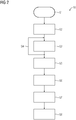
- a corresponding method for calibrating the imaging device 2 will be described with reference to FIG 2 , which schematically shows an exemplary flow chart 10, illustrating multiple process steps.
- the method starts with a process step S1, wherein the phantom 4 is positioned in a first position inside a maximum detection range of the imaging device 2 - in this case on the patient support 3. While the phantom 4 is arranged in this first position, at least one image of the phantom 4 is taken or acquired using the imaging device 4. Also, a corresponding pose of the imaging device 2 is recorded. In practicality, multiple images of the phantom 4 or parts thereof may be acquired from different angles or perspectives. This means that while the phantom 4 remains in the first position, the imaging device 2 can be moved to different imaging positions around the phantom 4. In this case, the corresponding pose of the imaging device 2 is recorded for each of the multiple acquired images.
- a process step S3 the phantom 4 is moved out of the first position and into another position inside the maximum detection range of the imaging device 2. While the phantom 4 is being moved, the imaging device 2 can remain stationary. Analogous to the first position, at least one image of the phantom 4 or a part thereof is then taken in the new other position of the phantom 4 using the imaging device 2., Corresponding poses of the imaging device 2 are recorded for each image.
- This process of moving the phantom 4 into a new position and then taking at least one respective image can be repeated multiple times in a process step S4, which is correspondingly indicated in FIG 2 as a loop.
- the motion or movement of the phantom 4 is tracked relative to the first and/or its respective previous position. Moving the phantom 4 and tracking its movement or motion including its respective current position can be achieved in one or more of multiple different ways.
- the patient support 3 can be adjusted in terms of its position and orientation to move the phantom 4 placed thereon through at least part of the maximum detection range of the imaging device 2.
- the phantom 4 is placed upon a linear stage 6, which itself is attached to or placed upon the patient support 3.
- the phantom 4 can be moved by means of the linear stage 6. It can also be possible, to use multiple linear stages 6 in combination to move the phantom 4 in different directions or along different axes independently.
- a ruler device 7 is provided as part of the linear stage 6 or as a separate device.
- the ruler device 7 can mechanically track the motion and/or a respective current position of the phantom 4 when the phantom 4 is moved along the ruler device 7.
- the ruler device 7 can comprise multiple notches or recesses.
- the phantom 4 can correspondingly comprise a protrusion which can fit or snap into each one of the notches or recesses of the ruler device 7, thereby giving a precise location for the phantom 4, at least with respect to the ruler device 7.
- these can track the motion and position of the phantom 4 as part of their function.
- these can track the motion and position of the phantom 4 as part of their function.
- one or more different ways of tracking the motion and position of the phantom 4 can be employed.
- the imaging device 2 itself can be used to track the motion of the phantom 4.
- the imaging device 2 can be kept stationary while the phantom 4 is being moved from one position to the next. Then, while the phantom 4 is kept stationary in its respective new or current position, the imaging device 2 is moved correspondingly, typically in the same direction as the respective foregoing motion of the phantom 4. This stepwise alternating movement of the phantom 4 and the imaging device 2 can be repeated multiple times. During this process the phantom 4 is at least partly kept inside a respective current field of view of the imaging device 2.
- a portion of the phantom 4 comprising at least a part of the pattern of markers 5 is kept inside the field of view, wherein the part of the pattern of markers 5 is sufficient to uniquely and unambiguously derive the respective pose of the phantom 4 from corresponding images or image data acquired using the imaging device 2.
- a camera 8 and/or a laser distance meter 9 is or are attached to the phantom 4.
- the camera 8 can be used to image and track features of a surrounding room in which the imaging device 2 is presently installed and/or stationary features of the imaging device 2 itself and/or the patient support 3.
- a SLAM-technique can then be used for building a map of the surroundings and to determine and track the position of the phantom 4 with respect to these surroundings.
- the laser distance meter 9 can be used to continuously measure a distance between it and, for example, a wall of the surrounding room. By assuming that the wall remains stationary and analysing any changes in the measured distance, the relative motion of the phantom 4 can be determined.
- Results from different methods can also be used to provide redundancy as a safety measure against failure of a method or component.
- the results of multiple different methods can also be used to verify or plausibilize the results of one or more respective other methods.
- a process step S5 the imaging device 2 is then calibrated based on the acquired results or calibration data, i.e. based on the acquired images, the corresponding recorded poses of the imaging device 2, and the tracked motion of the phantom 4 and/or results derived therefrom.
- a 3D-dataset of a patient is then acquired using the medical imaging device 2 in a process step S6.
- a process step S7 which might take place for example several hours or days after process step S6, at least one, typically multiple 2D-images of the same patient are acquired using the imaging device 2, for example, as part of a medical procedure.
- the imaging device 2 is moved during this procedure, a 2D3D-registration between the respective currently acquired 2D-images and the 3D-dataset previously acquired in process step S6 is necessary to retain data consistency and provide the medical personnel with needed information or insight about the state of the patient and/or the procedure without subjecting the patient to unnecessary high doses of radiation, which would result from acquiring another full 3D-dataset during the medical procedure.
- the 2D3D-registration using the previously acquired calibration data for the imaging device 2 is then performed in a process step S8.
- the presently described examples illustrate how a calibration of a medical imaging device, such as the imaging device 2, can be improved by extending a calibration space through relatively simple and inexpensive means by tracking a motion of the phantom 2 during the calibration process to accurately map a larger portion the maximum detection range of the respective medical imaging device.
- the improved calibration can then be used to perform a 2D3D-registration with improved accuracy and reliability, since because of the increased calibration space no or less interpolation and/or extrapolation is required.
Landscapes
- Health & Medical Sciences (AREA)
- Life Sciences & Earth Sciences (AREA)
- Engineering & Computer Science (AREA)
- Medical Informatics (AREA)
- Surgery (AREA)
- Nuclear Medicine, Radiotherapy & Molecular Imaging (AREA)
- Heart & Thoracic Surgery (AREA)
- Animal Behavior & Ethology (AREA)
- Veterinary Medicine (AREA)
- Pathology (AREA)
- Radiology & Medical Imaging (AREA)
- Biomedical Technology (AREA)
- Public Health (AREA)
- Molecular Biology (AREA)
- General Health & Medical Sciences (AREA)
- Physics & Mathematics (AREA)
- Biophysics (AREA)
- High Energy & Nuclear Physics (AREA)
- Optics & Photonics (AREA)
- Pulmonology (AREA)
- Theoretical Computer Science (AREA)
- Oral & Maxillofacial Surgery (AREA)
- Gynecology & Obstetrics (AREA)
- Vascular Medicine (AREA)
- Dentistry (AREA)
- Apparatus For Radiation Diagnosis (AREA)
- Measurement Of The Respiration, Hearing Ability, Form, And Blood Characteristics Of Living Organisms (AREA)
Priority Applications (3)
| Application Number | Priority Date | Filing Date | Title |
|---|---|---|---|
| EP17210234.5A EP3501397B8 (de) | 2017-12-22 | 2017-12-22 | Verfahren zum kalibrieren einer medizinischen bildgebungsvorrichtung, verfahren zur durchführung einer 2d-3d-registrierung und system mit einer medizinischen bildgebungsvorrichtung |
| CN201811559630.7A CN109953767B (zh) | 2017-12-22 | 2018-12-19 | 用于校准医学成像设备、用于执行配准的方法以及系统 |
| US16/231,509 US10828006B2 (en) | 2017-12-22 | 2018-12-22 | Method for calibrating a medical imaging device, method for performing a 2D-3D registration, and system including a medical imaging device |
Applications Claiming Priority (1)
| Application Number | Priority Date | Filing Date | Title |
|---|---|---|---|
| EP17210234.5A EP3501397B8 (de) | 2017-12-22 | 2017-12-22 | Verfahren zum kalibrieren einer medizinischen bildgebungsvorrichtung, verfahren zur durchführung einer 2d-3d-registrierung und system mit einer medizinischen bildgebungsvorrichtung |
Publications (3)
| Publication Number | Publication Date |
|---|---|
| EP3501397A1 true EP3501397A1 (de) | 2019-06-26 |
| EP3501397B1 EP3501397B1 (de) | 2024-01-24 |
| EP3501397B8 EP3501397B8 (de) | 2024-02-28 |
Family
ID=60782104
Family Applications (1)
| Application Number | Title | Priority Date | Filing Date |
|---|---|---|---|
| EP17210234.5A Active EP3501397B8 (de) | 2017-12-22 | 2017-12-22 | Verfahren zum kalibrieren einer medizinischen bildgebungsvorrichtung, verfahren zur durchführung einer 2d-3d-registrierung und system mit einer medizinischen bildgebungsvorrichtung |
Country Status (3)
| Country | Link |
|---|---|
| US (1) | US10828006B2 (de) |
| EP (1) | EP3501397B8 (de) |
| CN (1) | CN109953767B (de) |
Cited By (1)
| Publication number | Priority date | Publication date | Assignee | Title |
|---|---|---|---|---|
| EP4201333A1 (de) * | 2021-12-22 | 2023-06-28 | Siemens Healthineers International AG | Universelles phantom zur kalibrierung und verifizierung optischer und strahlungssysteme |
Families Citing this family (4)
| Publication number | Priority date | Publication date | Assignee | Title |
|---|---|---|---|---|
| WO2019228530A1 (en) * | 2018-05-31 | 2019-12-05 | Shanghai United Imaging Healthcare Co., Ltd. | Systems and methods for controllinig an x-ray imaging device |
| CN112085797B (zh) * | 2019-06-12 | 2024-07-19 | 通用电气精准医疗有限责任公司 | 3d相机-医疗成像设备坐标系校准系统和方法及其应用 |
| CN110812718B (zh) * | 2019-12-13 | 2022-02-15 | 安徽省立医院 | 放疗用摆位装置和放疗摆位方法 |
| JP1705623S (de) * | 2021-04-15 | 2022-01-21 |
Citations (8)
| Publication number | Priority date | Publication date | Assignee | Title |
|---|---|---|---|---|
| US20070172033A1 (en) * | 2004-12-17 | 2007-07-26 | Sebastien Gorges | Method and apparatus for acquisition geometry of an imaging system |
| US20100204562A1 (en) * | 2009-02-12 | 2010-08-12 | Sebastien Gorges | Calibration procedure for the relative position of a table and c-arm on a medical imaging system |
| US20100246778A1 (en) * | 2009-03-24 | 2010-09-30 | Benno Heigl | Method for Calibrating the Position of a Laser Fan Beam Relative to the Projection Geometry of an X-Ray Device and X-Ray Device |
| US20110257508A1 (en) * | 2010-04-15 | 2011-10-20 | Siemens Aktiengesellschaft | Device For Supporting, Scanning, Tomographically Displaying A Patient And Carrying Out An Intervention And Method For Determining The Spatial Relation Between Optical Recordings And Tomographic Displays |
| DE102011005993A1 (de) * | 2011-03-23 | 2012-09-27 | Siemens Aktiengesellschaft | Testvorrichtung und Verfahren zum Testen einer Röntgenvorrichtung |
| DE102011114333A1 (de) * | 2011-09-24 | 2013-03-28 | Ziehm Imaging Gmbh | Verfahren zur Registrierung eines Röntgenvolumens mit einem Lageerfassungssystem unter Verwendung eines Registrierphantoms |
| US20140350387A1 (en) * | 2011-05-12 | 2014-11-27 | The Johns Hopkins University | Electromagnetic tracking system and methods of using same |
| JP2015123317A (ja) * | 2013-12-27 | 2015-07-06 | 株式会社島津製作所 | 放射線撮影装置 |
Family Cites Families (4)
| Publication number | Priority date | Publication date | Assignee | Title |
|---|---|---|---|---|
| US20090306497A1 (en) * | 2006-05-26 | 2009-12-10 | Koninklijke Philips Electronics N.V. | Calibration method for catheter tracking system using medical imaging data |
| JP5663245B2 (ja) | 2010-09-07 | 2015-02-04 | 株式会社日立メディコ | X線ct装置 |
| WO2015051468A1 (en) * | 2013-10-10 | 2015-04-16 | Shahram Amiri | Tracking system for imaging machines and related apparatus |
| EP3082612A2 (de) * | 2013-12-18 | 2016-10-26 | Koninklijke Philips N.V. | Auf elektromagnetischem tracker basierende ultraschallsondenkalibrierung |
-
2017
- 2017-12-22 EP EP17210234.5A patent/EP3501397B8/de active Active
-
2018
- 2018-12-19 CN CN201811559630.7A patent/CN109953767B/zh active Active
- 2018-12-22 US US16/231,509 patent/US10828006B2/en active Active
Patent Citations (8)
| Publication number | Priority date | Publication date | Assignee | Title |
|---|---|---|---|---|
| US20070172033A1 (en) * | 2004-12-17 | 2007-07-26 | Sebastien Gorges | Method and apparatus for acquisition geometry of an imaging system |
| US20100204562A1 (en) * | 2009-02-12 | 2010-08-12 | Sebastien Gorges | Calibration procedure for the relative position of a table and c-arm on a medical imaging system |
| US20100246778A1 (en) * | 2009-03-24 | 2010-09-30 | Benno Heigl | Method for Calibrating the Position of a Laser Fan Beam Relative to the Projection Geometry of an X-Ray Device and X-Ray Device |
| US20110257508A1 (en) * | 2010-04-15 | 2011-10-20 | Siemens Aktiengesellschaft | Device For Supporting, Scanning, Tomographically Displaying A Patient And Carrying Out An Intervention And Method For Determining The Spatial Relation Between Optical Recordings And Tomographic Displays |
| DE102011005993A1 (de) * | 2011-03-23 | 2012-09-27 | Siemens Aktiengesellschaft | Testvorrichtung und Verfahren zum Testen einer Röntgenvorrichtung |
| US20140350387A1 (en) * | 2011-05-12 | 2014-11-27 | The Johns Hopkins University | Electromagnetic tracking system and methods of using same |
| DE102011114333A1 (de) * | 2011-09-24 | 2013-03-28 | Ziehm Imaging Gmbh | Verfahren zur Registrierung eines Röntgenvolumens mit einem Lageerfassungssystem unter Verwendung eines Registrierphantoms |
| JP2015123317A (ja) * | 2013-12-27 | 2015-07-06 | 株式会社島津製作所 | 放射線撮影装置 |
Non-Patent Citations (1)
| Title |
|---|
| GORGES S ET AL: "Model of a Vascular C-Arm for 3D Augmented Fluoroscopy in Interventional Radiology", 26 October 2005, MEDICAL IMAGE COMPUTING AND COMPUTER-ASSISTED INTERVENTION - MICCAI 2015 : 18TH INTERNATIONAL CONFERENCE, MUNICH, GERMANY, OCTOBER 5-9, 2015; PROCEEDINGS; [LECTURE NOTES IN COMPUTER SCIENCE; LECT.NOTES COMPUTER], SPRINGER INTERNATIONAL PUBLISHING, CH, ISBN: 978-3-642-38287-1, ISSN: 0302-9743, XP047461361 * |
Cited By (2)
| Publication number | Priority date | Publication date | Assignee | Title |
|---|---|---|---|---|
| EP4201333A1 (de) * | 2021-12-22 | 2023-06-28 | Siemens Healthineers International AG | Universelles phantom zur kalibrierung und verifizierung optischer und strahlungssysteme |
| US12144671B2 (en) | 2021-12-22 | 2024-11-19 | Siemens Healthineers International Ag | Universal phantom for calibration and verification of optical and radiation systems |
Also Published As
| Publication number | Publication date |
|---|---|
| US20190192105A1 (en) | 2019-06-27 |
| EP3501397B1 (de) | 2024-01-24 |
| CN109953767B (zh) | 2023-07-07 |
| EP3501397B8 (de) | 2024-02-28 |
| CN109953767A (zh) | 2019-07-02 |
| US10828006B2 (en) | 2020-11-10 |
Similar Documents
| Publication | Publication Date | Title |
|---|---|---|
| US10828006B2 (en) | Method for calibrating a medical imaging device, method for performing a 2D-3D registration, and system including a medical imaging device | |
| US12220180B2 (en) | Robotic surgery systems and surgical guidance methods thereof | |
| EP0919203B1 (de) | Rahmenlose stereotaktische chirurgische Vorrichtung | |
| JP6789953B2 (ja) | 動的基準点アレイ及び使用方法 | |
| CN107753105B (zh) | 定位手术用手术机器人系统及其控制方法 | |
| CN107753106B (zh) | 定位手术用手术机器人及其控制方法 | |
| US7097357B2 (en) | Method and system for improved correction of registration error in a fluoroscopic image | |
| EP2030169B1 (de) | Koordinatensystem-registration | |
| US6167292A (en) | Registering method and apparatus for robotic surgery, and a registering device constituting an application thereof | |
| US7672709B2 (en) | Determination of the position of a radiographic or radioscopic unit | |
| JP4524172B2 (ja) | 収集システムのアイソセンタに関して被検体を位置決めする方法及び装置 | |
| US20170296136A1 (en) | System and method for automatically determining calibration parameters of a fluoroscope | |
| CN105792748A (zh) | 光学运动跟踪系统与磁共振成像扫描仪之间的坐标变换的确定 | |
| US8022990B2 (en) | Systems and methods for on-line marker-less camera calibration using a position tracking system | |
| JP7089521B2 (ja) | 高速且つ自動化された超音波プローブ校正のためのシステム及び方法 | |
| JP2006175236A (ja) | 医用画像化装置の作動方法 | |
| CN115721415A (zh) | 一种软组织穿刺导航定位方法和系统 | |
| CN109464156A (zh) | 使用对接在空间对齐隔室内的检测器的移动x射线成像 | |
| US8182150B2 (en) | Calibration procedure for the relative position of a table and C-Arm on a medical imaging system | |
| US7621169B2 (en) | Systems and methods for integrating a navigation field replaceable unit into a fluoroscopy system | |
| JP7463625B2 (ja) | ナビゲーションサポート | |
| JP4330181B2 (ja) | 画像案内手術のための画像化モダリティー | |
| FI3653125T3 (fi) | Kefalometriseen kuvantamiseen tarkoitetun lääketieteellisen röntgensädekuvantamislaitteen kalibrointi | |
| CN110946600A (zh) | 用于记录图像数据的方法和医学成像系统 | |
| JP7076965B2 (ja) | X線診断装置、画像処理装置及び角度計測治具 |
Legal Events
| Date | Code | Title | Description |
|---|---|---|---|
| PUAI | Public reference made under article 153(3) epc to a published international application that has entered the european phase |
Free format text: ORIGINAL CODE: 0009012 |
|
| STAA | Information on the status of an ep patent application or granted ep patent |
Free format text: STATUS: THE APPLICATION HAS BEEN PUBLISHED |
|
| AK | Designated contracting states |
Kind code of ref document: A1 Designated state(s): AL AT BE BG CH CY CZ DE DK EE ES FI FR GB GR HR HU IE IS IT LI LT LU LV MC MK MT NL NO PL PT RO RS SE SI SK SM TR |
|
| AX | Request for extension of the european patent |
Extension state: BA ME |
|
| STAA | Information on the status of an ep patent application or granted ep patent |
Free format text: STATUS: REQUEST FOR EXAMINATION WAS MADE |
|
| 17P | Request for examination filed |
Effective date: 20190704 |
|
| RBV | Designated contracting states (corrected) |
Designated state(s): AL AT BE BG CH CY CZ DE DK EE ES FI FR GB GR HR HU IE IS IT LI LT LU LV MC MK MT NL NO PL PT RO RS SE SI SK SM TR |
|
| STAA | Information on the status of an ep patent application or granted ep patent |
Free format text: STATUS: EXAMINATION IS IN PROGRESS |
|
| 17Q | First examination report despatched |
Effective date: 20220502 |
|
| GRAP | Despatch of communication of intention to grant a patent |
Free format text: ORIGINAL CODE: EPIDOSNIGR1 |
|
| STAA | Information on the status of an ep patent application or granted ep patent |
Free format text: STATUS: GRANT OF PATENT IS INTENDED |
|
| INTG | Intention to grant announced |
Effective date: 20230811 |
|
| GRAS | Grant fee paid |
Free format text: ORIGINAL CODE: EPIDOSNIGR3 |
|
| GRAA | (expected) grant |
Free format text: ORIGINAL CODE: 0009210 |
|
| STAA | Information on the status of an ep patent application or granted ep patent |
Free format text: STATUS: THE PATENT HAS BEEN GRANTED |
|
| GRAT | Correction requested after decision to grant or after decision to maintain patent in amended form |
Free format text: ORIGINAL CODE: EPIDOSNCDEC |
|
| REG | Reference to a national code |
Ref country code: DE Ref legal event code: R081 Ref document number: 602017078659 Country of ref document: DE Owner name: SIEMENS HEALTHCARE GMBH, DE Free format text: FORMER OWNER: SIEMENS HEALTHCARE GMBH, MUENCHEN, DE Ref country code: DE Ref legal event code: R081 Ref document number: 602017078659 Country of ref document: DE Owner name: SIEMENS HEALTHINEERS AG, DE Free format text: FORMER OWNER: SIEMENS HEALTHCARE GMBH, MUENCHEN, DE |
|
| AK | Designated contracting states |
Kind code of ref document: B1 Designated state(s): AL AT BE BG CH CY CZ DE DK EE ES FI FR GB GR HR HU IE IS IT LI LT LU LV MC MK MT NL NO PL PT RO RS SE SI SK SM TR |
|
| REG | Reference to a national code |
Ref country code: GB Ref legal event code: FG4D |
|
| REG | Reference to a national code |
Ref country code: CH Ref legal event code: PK Free format text: BERICHTIGUNG B8 Ref country code: CH Ref legal event code: EP |
|
| REG | Reference to a national code |
Ref country code: DE Ref legal event code: R096 Ref document number: 602017078659 Country of ref document: DE |
|
| RAP2 | Party data changed (patent owner data changed or rights of a patent transferred) |
Owner name: SIEMENS HEALTHINEERS AG |
|
| REG | Reference to a national code |
Ref country code: DE Ref legal event code: R081 Ref document number: 602017078659 Country of ref document: DE Owner name: SIEMENS HEALTHINEERS AG, DE Free format text: FORMER OWNER: SIEMENS HEALTHINEERS AG, 91301 FORCHHEIM, DE Ref country code: IE Ref legal event code: FG4D Ref country code: DE Ref legal event code: R081 Ref document number: 602017078659 Country of ref document: DE Owner name: SIEMENS HEALTHCARE GMBH, DE Free format text: FORMER OWNER: SIEMENS HEALTHINEERS AG, 91301 FORCHHEIM, DE |
|
| REG | Reference to a national code |
Ref country code: DE Ref legal event code: R081 Ref document number: 602017078659 Country of ref document: DE Owner name: SIEMENS HEALTHINEERS AG, DE Free format text: FORMER OWNER: SIEMENS HEALTHCARE GMBH, MUENCHEN, DE |
|
| REG | Reference to a national code |
Ref country code: LT Ref legal event code: MG9D |
|
| REG | Reference to a national code |
Ref country code: NL Ref legal event code: MP Effective date: 20240124 |
|
| PG25 | Lapsed in a contracting state [announced via postgrant information from national office to epo] |
Ref country code: NL Free format text: LAPSE BECAUSE OF FAILURE TO SUBMIT A TRANSLATION OF THE DESCRIPTION OR TO PAY THE FEE WITHIN THE PRESCRIBED TIME-LIMIT Effective date: 20240124 |
|
| PG25 | Lapsed in a contracting state [announced via postgrant information from national office to epo] |
Ref country code: NL Free format text: LAPSE BECAUSE OF FAILURE TO SUBMIT A TRANSLATION OF THE DESCRIPTION OR TO PAY THE FEE WITHIN THE PRESCRIBED TIME-LIMIT Effective date: 20240124 |
|
| PG25 | Lapsed in a contracting state [announced via postgrant information from national office to epo] |
Ref country code: IS Free format text: LAPSE BECAUSE OF FAILURE TO SUBMIT A TRANSLATION OF THE DESCRIPTION OR TO PAY THE FEE WITHIN THE PRESCRIBED TIME-LIMIT Effective date: 20240524 |
|
| PG25 | Lapsed in a contracting state [announced via postgrant information from national office to epo] |
Ref country code: LT Free format text: LAPSE BECAUSE OF FAILURE TO SUBMIT A TRANSLATION OF THE DESCRIPTION OR TO PAY THE FEE WITHIN THE PRESCRIBED TIME-LIMIT Effective date: 20240124 |
|
| PG25 | Lapsed in a contracting state [announced via postgrant information from national office to epo] |
Ref country code: GR Free format text: LAPSE BECAUSE OF FAILURE TO SUBMIT A TRANSLATION OF THE DESCRIPTION OR TO PAY THE FEE WITHIN THE PRESCRIBED TIME-LIMIT Effective date: 20240425 |
|
| REG | Reference to a national code |
Ref country code: AT Ref legal event code: MK05 Ref document number: 1651532 Country of ref document: AT Kind code of ref document: T Effective date: 20240124 |
|
| PG25 | Lapsed in a contracting state [announced via postgrant information from national office to epo] |
Ref country code: RS Free format text: LAPSE BECAUSE OF FAILURE TO SUBMIT A TRANSLATION OF THE DESCRIPTION OR TO PAY THE FEE WITHIN THE PRESCRIBED TIME-LIMIT Effective date: 20240424 Ref country code: HR Free format text: LAPSE BECAUSE OF FAILURE TO SUBMIT A TRANSLATION OF THE DESCRIPTION OR TO PAY THE FEE WITHIN THE PRESCRIBED TIME-LIMIT Effective date: 20240124 |
|
| PG25 | Lapsed in a contracting state [announced via postgrant information from national office to epo] |
Ref country code: ES Free format text: LAPSE BECAUSE OF FAILURE TO SUBMIT A TRANSLATION OF THE DESCRIPTION OR TO PAY THE FEE WITHIN THE PRESCRIBED TIME-LIMIT Effective date: 20240124 |
|
| PG25 | Lapsed in a contracting state [announced via postgrant information from national office to epo] |
Ref country code: AT Free format text: LAPSE BECAUSE OF FAILURE TO SUBMIT A TRANSLATION OF THE DESCRIPTION OR TO PAY THE FEE WITHIN THE PRESCRIBED TIME-LIMIT Effective date: 20240124 |
|
| PG25 | Lapsed in a contracting state [announced via postgrant information from national office to epo] |
Ref country code: RS Free format text: LAPSE BECAUSE OF FAILURE TO SUBMIT A TRANSLATION OF THE DESCRIPTION OR TO PAY THE FEE WITHIN THE PRESCRIBED TIME-LIMIT Effective date: 20240424 Ref country code: NO Free format text: LAPSE BECAUSE OF FAILURE TO SUBMIT A TRANSLATION OF THE DESCRIPTION OR TO PAY THE FEE WITHIN THE PRESCRIBED TIME-LIMIT Effective date: 20240424 Ref country code: LT Free format text: LAPSE BECAUSE OF FAILURE TO SUBMIT A TRANSLATION OF THE DESCRIPTION OR TO PAY THE FEE WITHIN THE PRESCRIBED TIME-LIMIT Effective date: 20240124 Ref country code: IS Free format text: LAPSE BECAUSE OF FAILURE TO SUBMIT A TRANSLATION OF THE DESCRIPTION OR TO PAY THE FEE WITHIN THE PRESCRIBED TIME-LIMIT Effective date: 20240524 Ref country code: HR Free format text: LAPSE BECAUSE OF FAILURE TO SUBMIT A TRANSLATION OF THE DESCRIPTION OR TO PAY THE FEE WITHIN THE PRESCRIBED TIME-LIMIT Effective date: 20240124 Ref country code: GR Free format text: LAPSE BECAUSE OF FAILURE TO SUBMIT A TRANSLATION OF THE DESCRIPTION OR TO PAY THE FEE WITHIN THE PRESCRIBED TIME-LIMIT Effective date: 20240425 Ref country code: FI Free format text: LAPSE BECAUSE OF FAILURE TO SUBMIT A TRANSLATION OF THE DESCRIPTION OR TO PAY THE FEE WITHIN THE PRESCRIBED TIME-LIMIT Effective date: 20240124 Ref country code: ES Free format text: LAPSE BECAUSE OF FAILURE TO SUBMIT A TRANSLATION OF THE DESCRIPTION OR TO PAY THE FEE WITHIN THE PRESCRIBED TIME-LIMIT Effective date: 20240124 Ref country code: BG Free format text: LAPSE BECAUSE OF FAILURE TO SUBMIT A TRANSLATION OF THE DESCRIPTION OR TO PAY THE FEE WITHIN THE PRESCRIBED TIME-LIMIT Effective date: 20240124 Ref country code: AT Free format text: LAPSE BECAUSE OF FAILURE TO SUBMIT A TRANSLATION OF THE DESCRIPTION OR TO PAY THE FEE WITHIN THE PRESCRIBED TIME-LIMIT Effective date: 20240124 |
|
| PG25 | Lapsed in a contracting state [announced via postgrant information from national office to epo] |
Ref country code: PT Free format text: LAPSE BECAUSE OF FAILURE TO SUBMIT A TRANSLATION OF THE DESCRIPTION OR TO PAY THE FEE WITHIN THE PRESCRIBED TIME-LIMIT Effective date: 20240524 Ref country code: PL Free format text: LAPSE BECAUSE OF FAILURE TO SUBMIT A TRANSLATION OF THE DESCRIPTION OR TO PAY THE FEE WITHIN THE PRESCRIBED TIME-LIMIT Effective date: 20240124 |
|
| PG25 | Lapsed in a contracting state [announced via postgrant information from national office to epo] |
Ref country code: SE Free format text: LAPSE BECAUSE OF FAILURE TO SUBMIT A TRANSLATION OF THE DESCRIPTION OR TO PAY THE FEE WITHIN THE PRESCRIBED TIME-LIMIT Effective date: 20240124 Ref country code: PT Free format text: LAPSE BECAUSE OF FAILURE TO SUBMIT A TRANSLATION OF THE DESCRIPTION OR TO PAY THE FEE WITHIN THE PRESCRIBED TIME-LIMIT Effective date: 20240524 Ref country code: PL Free format text: LAPSE BECAUSE OF FAILURE TO SUBMIT A TRANSLATION OF THE DESCRIPTION OR TO PAY THE FEE WITHIN THE PRESCRIBED TIME-LIMIT Effective date: 20240124 Ref country code: LV Free format text: LAPSE BECAUSE OF FAILURE TO SUBMIT A TRANSLATION OF THE DESCRIPTION OR TO PAY THE FEE WITHIN THE PRESCRIBED TIME-LIMIT Effective date: 20240124 |
|
| PG25 | Lapsed in a contracting state [announced via postgrant information from national office to epo] |
Ref country code: DK Free format text: LAPSE BECAUSE OF FAILURE TO SUBMIT A TRANSLATION OF THE DESCRIPTION OR TO PAY THE FEE WITHIN THE PRESCRIBED TIME-LIMIT Effective date: 20240124 |
|
| PG25 | Lapsed in a contracting state [announced via postgrant information from national office to epo] |
Ref country code: SM Free format text: LAPSE BECAUSE OF FAILURE TO SUBMIT A TRANSLATION OF THE DESCRIPTION OR TO PAY THE FEE WITHIN THE PRESCRIBED TIME-LIMIT Effective date: 20240124 |
|
| PG25 | Lapsed in a contracting state [announced via postgrant information from national office to epo] |
Ref country code: CZ Free format text: LAPSE BECAUSE OF FAILURE TO SUBMIT A TRANSLATION OF THE DESCRIPTION OR TO PAY THE FEE WITHIN THE PRESCRIBED TIME-LIMIT Effective date: 20240124 Ref country code: EE Free format text: LAPSE BECAUSE OF FAILURE TO SUBMIT A TRANSLATION OF THE DESCRIPTION OR TO PAY THE FEE WITHIN THE PRESCRIBED TIME-LIMIT Effective date: 20240124 |
|
| REG | Reference to a national code |
Ref country code: DE Ref legal event code: R097 Ref document number: 602017078659 Country of ref document: DE |
|
| PG25 | Lapsed in a contracting state [announced via postgrant information from national office to epo] |
Ref country code: SK Free format text: LAPSE BECAUSE OF FAILURE TO SUBMIT A TRANSLATION OF THE DESCRIPTION OR TO PAY THE FEE WITHIN THE PRESCRIBED TIME-LIMIT Effective date: 20240124 |
|
| PG25 | Lapsed in a contracting state [announced via postgrant information from national office to epo] |
Ref country code: SM Free format text: LAPSE BECAUSE OF FAILURE TO SUBMIT A TRANSLATION OF THE DESCRIPTION OR TO PAY THE FEE WITHIN THE PRESCRIBED TIME-LIMIT Effective date: 20240124 Ref country code: SK Free format text: LAPSE BECAUSE OF FAILURE TO SUBMIT A TRANSLATION OF THE DESCRIPTION OR TO PAY THE FEE WITHIN THE PRESCRIBED TIME-LIMIT Effective date: 20240124 Ref country code: RO Free format text: LAPSE BECAUSE OF FAILURE TO SUBMIT A TRANSLATION OF THE DESCRIPTION OR TO PAY THE FEE WITHIN THE PRESCRIBED TIME-LIMIT Effective date: 20240124 Ref country code: EE Free format text: LAPSE BECAUSE OF FAILURE TO SUBMIT A TRANSLATION OF THE DESCRIPTION OR TO PAY THE FEE WITHIN THE PRESCRIBED TIME-LIMIT Effective date: 20240124 Ref country code: DK Free format text: LAPSE BECAUSE OF FAILURE TO SUBMIT A TRANSLATION OF THE DESCRIPTION OR TO PAY THE FEE WITHIN THE PRESCRIBED TIME-LIMIT Effective date: 20240124 Ref country code: CZ Free format text: LAPSE BECAUSE OF FAILURE TO SUBMIT A TRANSLATION OF THE DESCRIPTION OR TO PAY THE FEE WITHIN THE PRESCRIBED TIME-LIMIT Effective date: 20240124 |
|
| PLBE | No opposition filed within time limit |
Free format text: ORIGINAL CODE: 0009261 |
|
| STAA | Information on the status of an ep patent application or granted ep patent |
Free format text: STATUS: NO OPPOSITION FILED WITHIN TIME LIMIT |
|
| PG25 | Lapsed in a contracting state [announced via postgrant information from national office to epo] |
Ref country code: IT Free format text: LAPSE BECAUSE OF FAILURE TO SUBMIT A TRANSLATION OF THE DESCRIPTION OR TO PAY THE FEE WITHIN THE PRESCRIBED TIME-LIMIT Effective date: 20240124 |
|
| PG25 | Lapsed in a contracting state [announced via postgrant information from national office to epo] |
Ref country code: IT Free format text: LAPSE BECAUSE OF FAILURE TO SUBMIT A TRANSLATION OF THE DESCRIPTION OR TO PAY THE FEE WITHIN THE PRESCRIBED TIME-LIMIT Effective date: 20240124 |
|
| 26N | No opposition filed |
Effective date: 20241025 |
|
| PGFP | Annual fee paid to national office [announced via postgrant information from national office to epo] |
Ref country code: FR Payment date: 20241213 Year of fee payment: 8 |
|
| PGFP | Annual fee paid to national office [announced via postgrant information from national office to epo] |
Ref country code: DE Payment date: 20250220 Year of fee payment: 8 |
|
| PG25 | Lapsed in a contracting state [announced via postgrant information from national office to epo] |
Ref country code: SI Free format text: LAPSE BECAUSE OF FAILURE TO SUBMIT A TRANSLATION OF THE DESCRIPTION OR TO PAY THE FEE WITHIN THE PRESCRIBED TIME-LIMIT Effective date: 20240124 |
|
| PGFP | Annual fee paid to national office [announced via postgrant information from national office to epo] |
Ref country code: GB Payment date: 20250115 Year of fee payment: 8 |
|
| PG25 | Lapsed in a contracting state [announced via postgrant information from national office to epo] |
Ref country code: MC Free format text: LAPSE BECAUSE OF FAILURE TO SUBMIT A TRANSLATION OF THE DESCRIPTION OR TO PAY THE FEE WITHIN THE PRESCRIBED TIME-LIMIT Effective date: 20240124 |
|
| REG | Reference to a national code |
Ref country code: CH Ref legal event code: PL |
|
| PG25 | Lapsed in a contracting state [announced via postgrant information from national office to epo] |
Ref country code: LU Free format text: LAPSE BECAUSE OF NON-PAYMENT OF DUE FEES Effective date: 20241222 |
|
| REG | Reference to a national code |
Ref country code: BE Ref legal event code: MM Effective date: 20241231 |
|
| PG25 | Lapsed in a contracting state [announced via postgrant information from national office to epo] |
Ref country code: BE Free format text: LAPSE BECAUSE OF NON-PAYMENT OF DUE FEES Effective date: 20241231 |
|
| PG25 | Lapsed in a contracting state [announced via postgrant information from national office to epo] |
Ref country code: CH Free format text: LAPSE BECAUSE OF NON-PAYMENT OF DUE FEES Effective date: 20241231 |
|
| PG25 | Lapsed in a contracting state [announced via postgrant information from national office to epo] |
Ref country code: IE Free format text: LAPSE BECAUSE OF NON-PAYMENT OF DUE FEES Effective date: 20241222 |