EP3501338B1 - Längenverstellbare säule und herstellungsverfahren dafür, möbelstück - Google Patents
Längenverstellbare säule und herstellungsverfahren dafür, möbelstück Download PDFInfo
- Publication number
- EP3501338B1 EP3501338B1 EP18212875.1A EP18212875A EP3501338B1 EP 3501338 B1 EP3501338 B1 EP 3501338B1 EP 18212875 A EP18212875 A EP 18212875A EP 3501338 B1 EP3501338 B1 EP 3501338B1
- Authority
- EP
- European Patent Office
- Prior art keywords
- section
- base body
- column
- standpipe
- longitudinal axis
- Prior art date
- Legal status (The legal status is an assumption and is not a legal conclusion. Google has not performed a legal analysis and makes no representation as to the accuracy of the status listed.)
- Active
Links
Images


Classifications
-
- F—MECHANICAL ENGINEERING; LIGHTING; HEATING; WEAPONS; BLASTING
- F16—ENGINEERING ELEMENTS AND UNITS; GENERAL MEASURES FOR PRODUCING AND MAINTAINING EFFECTIVE FUNCTIONING OF MACHINES OR INSTALLATIONS; THERMAL INSULATION IN GENERAL
- F16M—FRAMES, CASINGS OR BEDS OF ENGINES, MACHINES OR APPARATUS, NOT SPECIFIC TO ENGINES, MACHINES OR APPARATUS PROVIDED FOR ELSEWHERE; STANDS; SUPPORTS
- F16M11/00—Stands or trestles as supports for apparatus or articles placed thereon ; Stands for scientific apparatus such as gravitational force meters
- F16M11/20—Undercarriages with or without wheels
- F16M11/24—Undercarriages with or without wheels changeable in height or length of legs, also for transport only, e.g. by means of tubes screwed into each other
- F16M11/26—Undercarriages with or without wheels changeable in height or length of legs, also for transport only, e.g. by means of tubes screwed into each other by telescoping, with or without folding
- F16M11/28—Undercarriages for supports with one single telescoping pillar
-
- A—HUMAN NECESSITIES
- A47—FURNITURE; DOMESTIC ARTICLES OR APPLIANCES; COFFEE MILLS; SPICE MILLS; SUCTION CLEANERS IN GENERAL
- A47C—CHAIRS; SOFAS; BEDS
- A47C3/00—Chairs characterised by structural features; Chairs or stools with rotatable or vertically-adjustable seats
- A47C3/20—Chairs or stools with vertically-adjustable seats
- A47C3/30—Chairs or stools with vertically-adjustable seats with vertically-acting fluid cylinder
-
- A—HUMAN NECESSITIES
- A47—FURNITURE; DOMESTIC ARTICLES OR APPLIANCES; COFFEE MILLS; SPICE MILLS; SUCTION CLEANERS IN GENERAL
- A47B—TABLES; DESKS; OFFICE FURNITURE; CABINETS; DRAWERS; GENERAL DETAILS OF FURNITURE
- A47B9/00—Tables with tops of variable height
- A47B9/10—Tables with tops of variable height with vertically-acting fluid cylinder
-
- A—HUMAN NECESSITIES
- A47—FURNITURE; DOMESTIC ARTICLES OR APPLIANCES; COFFEE MILLS; SPICE MILLS; SUCTION CLEANERS IN GENERAL
- A47B—TABLES; DESKS; OFFICE FURNITURE; CABINETS; DRAWERS; GENERAL DETAILS OF FURNITURE
- A47B9/00—Tables with tops of variable height
- A47B9/20—Telescopic guides
-
- A—HUMAN NECESSITIES
- A47—FURNITURE; DOMESTIC ARTICLES OR APPLIANCES; COFFEE MILLS; SPICE MILLS; SUCTION CLEANERS IN GENERAL
- A47B—TABLES; DESKS; OFFICE FURNITURE; CABINETS; DRAWERS; GENERAL DETAILS OF FURNITURE
- A47B2200/00—General construction of tables or desks
- A47B2200/0035—Tables or desks with features relating to adjustability or folding
- A47B2200/005—Leg adjustment
- A47B2200/0051—Telescopic
-
- F—MECHANICAL ENGINEERING; LIGHTING; HEATING; WEAPONS; BLASTING
- F16—ENGINEERING ELEMENTS AND UNITS; GENERAL MEASURES FOR PRODUCING AND MAINTAINING EFFECTIVE FUNCTIONING OF MACHINES OR INSTALLATIONS; THERMAL INSULATION IN GENERAL
- F16C—SHAFTS; FLEXIBLE SHAFTS; ELEMENTS OR CRANKSHAFT MECHANISMS; ROTARY BODIES OTHER THAN GEARING ELEMENTS; BEARINGS
- F16C29/00—Bearings for parts moving only linearly
- F16C29/02—Sliding-contact bearings
-
- F—MECHANICAL ENGINEERING; LIGHTING; HEATING; WEAPONS; BLASTING
- F16—ENGINEERING ELEMENTS AND UNITS; GENERAL MEASURES FOR PRODUCING AND MAINTAINING EFFECTIVE FUNCTIONING OF MACHINES OR INSTALLATIONS; THERMAL INSULATION IN GENERAL
- F16D—COUPLINGS FOR TRANSMITTING ROTATION; CLUTCHES; BRAKES
- F16D3/00—Yielding couplings, i.e. with means permitting movement between the connected parts during the drive
- F16D3/02—Yielding couplings, i.e. with means permitting movement between the connected parts during the drive adapted to specific functions
- F16D3/06—Yielding couplings, i.e. with means permitting movement between the connected parts during the drive adapted to specific functions specially adapted to allow axial displacement
-
- F—MECHANICAL ENGINEERING; LIGHTING; HEATING; WEAPONS; BLASTING
- F16—ENGINEERING ELEMENTS AND UNITS; GENERAL MEASURES FOR PRODUCING AND MAINTAINING EFFECTIVE FUNCTIONING OF MACHINES OR INSTALLATIONS; THERMAL INSULATION IN GENERAL
- F16F—SPRINGS; SHOCK-ABSORBERS; MEANS FOR DAMPING VIBRATION
- F16F9/00—Springs, vibration-dampers, shock-absorbers, or similarly-constructed movement-dampers using a fluid or the equivalent as damping medium
- F16F9/32—Details
- F16F9/56—Means for adjusting the length of, or for locking, the spring or damper, e.g. at the end of the stroke
Definitions
- the invention relates to a length-adjustable column with a standpipe with a longitudinal axis and a length adjustment device arranged in the standpipe with a section that is mounted displaceably with respect to the standpipe along the longitudinal axis.
- the invention also relates to a manufacturing method for a length-adjustable column and a piece of furniture with a length-adjustable column.
- Length-adjustable columns for example for adjusting the height of chairs or tables, are known from the prior art.
- a rotation about this axis is also possible with these columns.
- the rotation should be prevented, for example in the case of seating in an event hall that should always be aligned with a stage.
- an adjustable-length column for chairs, tables or the like in which a housing of a length-adjusting element is guided displaceably along an axis in a standpipe. A rotation of the housing relative to the standpipe about the axis is prevented by the interaction of a guide of the standpipe with an anti-rotation element fastened to the housing.
- the anti-rotation element may be deformed and / or the anti-rotation element may become detached from the housing. As a result, anti-rotation protection is no longer guaranteed and the length adjustment can be blocked by jamming the anti-rotation element with the guide.
- the object of the invention is therefore to create a column which is adjustable in length and is non-rotatable and which is easy and inexpensive to manufacture and which offers greater reliability and longevity than columns of the generic type without requiring additional installation space.
- Another object of the invention is to create a simple and inexpensive manufacturing method for such a column.
- One object of the invention is a length-adjustable column with a standpipe with a longitudinal axis. Also included is a length adjustment device which is arranged in the standpipe and has a section that is mounted displaceably along the longitudinal axis with respect to the standpipe. At least in part of a stroke of the length adjustment device, the section can be guided or supported so as to be rotatable about the longitudinal axis with respect to the standpipe.
- the length-adjustable column comprises an anti-rotation device for securing the section against rotation about the longitudinal axis relative to the standpipe. The invention can be used particularly advantageously when the anti-rotation device acts over the entire stroke.
- the standpipe and / or the section is round in cross section with respect to the longitudinal axis.
- the standpipe is particularly preferably cylindrical, at least in sections, so that it is particularly easy to manufacture and due to the round cross-section and the associated isotropic force absorption capacity around the longitudinal axis is mechanically stable. If the standpipe and section are cylindrical, there is the additional advantage that they cannot jam with one another, for example through a slight rotation relative to one another about the longitudinal axis.
- the length adjustment device is preferably arranged coaxially in the standpipe in order to ensure a particularly high mechanical stability with simultaneous reliable and smooth guidance of the length adjustment device in the standpipe along the longitudinal axis.
- the length adjustment device can for example comprise a pneumatic or hydropneumatic piston-cylinder unit, in particular a gas pressure spring, wherein the section can in particular be part of a cylinder of the piston-cylinder unit.
- the anti-rotation device advantageously ensures that the section does not rotate about the longitudinal axis with respect to the standpipe. If the standpipe is, for example, fixedly arranged on a surface, the column can be used to adjust an element rigidly connected to the section, for example a seat surface of a chair, for example along a vertical axis without being rotatable about this axis.
- the anti-rotation device includes an inner member attached to an outer surface of the section and an outer member attached to an inner surface of the standpipe.
- the inner element advantageously interacts with the outer element in a form-fitting manner with respect to a rotation about the longitudinal axis and is, for example, guided displaceably along the longitudinal axis by the outer element.
- the inner element is connected to the section by an integral connecting layer.
- the connecting layer for example a weld seam, a soldering layer and / or an adhesive layer, produces a mechanically particularly stable connection between the inner element and the section.
- the connection is in particular much more stable than one, for example in DE 43 13 766 A1 described connection of an anti-rotation profile with a housing by thermal pressing.
- the particularly stable connection ensures that the anti-rotation device can withstand higher torques without the inner element becoming detached from the section. This increases reliability and longevity the pillar.
- the inner element consists of a material with at least as high strength as the section.
- High strength means that the material can withstand high stress or pressure without deforming or failing.
- a material of high strength ensures that the anti-rotation device can withstand high torques without the inner element being deformed, which could lead to jamming with the outer element and / or a loss of the anti-rotation function.
- structures, for example projections, of the inner element, which interact positively with the outer element to prevent rotation can be made smaller when using a material of high strength, so that the inner element and thus also the column as a whole can be more compact.
- an anti-rotation profile made of a less rigid material than the housing to which it is applied is used in order not to damage the housing when the anti-rotation profile is applied, in particular with a forming process such as thermal pressing. Damage to the housing is to be avoided in particular for safety reasons if it is part of a pressure cylinder, for example a gas pressure spring. Only through the connection according to the invention of the inner element to the section is it possible to use a stronger material for the inner element without running the risk of damaging the section.
- the inner element and the section are preferably made of the same material.
- the inner element consists of a steel, in particular with a hardened surface
- the section consists for example of a steel, in particular with a hardened surface.
- a hardened surface can be provided, for example, by nitriding the steel. It can reduce wear, in particular of the inner element when it is displaced along the outer element.
- the outer element can consist of a plastic, in particular a self-lubricating plastic, for example polyoxymethylene.
- the outer element can be made of a plastic, in particular also with one according to the invention by grooves structured inner surface, can be produced quickly and inexpensively.
- an outer element made of plastic generally has a lower mass than made of a metal or ceramic material.
- a, in particular self-lubricating, plastic has a low friction compared to an inner element, for example made of metal, so that the outer element and the inner element can be easily displaced relative to one another and thus a length of the column can be easily adjusted.
- the outer element Since the outer element is arranged on the outside of the inner element with respect to the longitudinal axis, it has a larger circumference, and structures that interact positively against rotation can be designed with a greater material thickness on the outer element than on the inner element. Therefore, even with a material of the outer element, for example a plastic that is less rigid than a material of the inner element, which according to the invention is a steel, a sufficiently high stability of the structures of the outer element and thus an anti-twist protection against high torques can be ensured.
- the inner element and the outer element are shaped complementary to one another.
- “complementarily shaped” is understood to mean that a radial distance to the longitudinal axis between the inner element and the outer element is the same in all radial directions. The distance is advantageously as small as possible.
- the complementary shape allows a particularly stable and precise guidance of the inner element through the outer element, in particular when the distance is small, that is to say there is only little mechanical play.
- the outer element comprises a cylindrical outer base body with a number of, for example one, two, three, four or five grooves in an inner surface of the outer base body.
- the inner element comprises a cylindrical base body with a number of, for example one, two, three, four or five projections engaging in the grooves on an outer surface of the base body.
- the grooves and / or projections are evenly distributed around the longitudinal axis, that is to say at the same angular distance from one another, so that a uniform force distribution is ensured.
- the outer element and / or the inner element can in particular be shaped like the guide bushing or the anti-rotation profile from column 2, line 56 to column 3, line 62 of the publication DE 4313766 A1 which is incorporated herein by reference.
- the outer element can be designed in one piece with the standpipe, for example made of plastic, in order to reduce the number of components of the column and thus the production costs.
- a transition area from projections of the inner element to an inner base body of the inner element and / or an end of the projections facing away from the inner base body can be rounded.
- the roundings prevent the inner element from canting with the outer element and prevent stress concentrations from occurring in the transition area or at the end of the projections, which could lead to material failure.
- a disadvantage of the roundings can be that they reduce an effective contact area between the inner element and the outer element for absorbing a torque between the elements. This could reduce the maximum torque that the anti-rotation device withstands. However, such an effect can be compensated according to the invention, for example by selecting a sufficiently strong material for the inner element.
- an inner element length parallel to the longitudinal axis corresponds to at least the sum of an outer element length parallel to the longitudinal axis and a stroke of the length adjustment device. This ensures that the outer element can guide the inner element over the entire stroke path with the entire outer element length, so that a particularly stable and precise guidance results.
- an outer diameter of the section in particular at an, advantageously uncontrolled, ambient temperature of 10 ° C. to 30 ° C., preferably 15 ° C. to 25 ° C., is less than or equal to an inner diameter of the inner base body is, the section can be arranged particularly easily in the inner base body, for example pushed into it. In particular, it is not necessary to reshape the section or the inner base body for the arrangement, for example mechanically or by heating or cooling. This eliminates additional process steps and the risk of damage to the section or the inner base body is reduced.
- a very firm connection of the inner base body to the section can be achieved.
- a large-area, uniform connection can be achieved, which leads to a uniform stress distribution and thus a reduced mechanical point loading of the section and the inner base body.
- the method can include application, for example brushing or spraying, of an adhesive, preferably a metal adhesive, on an outer surface of the section and / or an inner surface of the inner base body, in particular before the arrangement.
- an adhesive for example a two-component adhesive
- a materially bonded connection can take place without incurring the risk of corrosion, as is the case with a welded connection, for example.
- the application can take place on the entire outer surface of the section. As a result, a large-area and even gluing with a high level of strength and even stress distribution is achieved.
- the application can be carried out in an amount sufficient to fill an intermediate space that forms between the section and the inner base body when it is arranged.
- the adhesive can thus advantageously compensate for slight deviations of the section and / or the inner element from their target dimensions, so that these can be manufactured with further tolerances and thus faster and / or more cost-effectively.
- slight deviations in the outer diameter of the section or the inner diameter of the inner base body from their target values can be compensated for without impairing the strength of the connection between the section and the inner element.
- the section and / or the inner element can be manufactured with wider tolerances than if they were made by pressing as in the prior art (e.g. DE 4313766 A1 ) should be connected.
- Providing can include cold drawing of the section and / or of the inner base body.
- the section and the inner base body can be manufactured quickly and inexpensively by cold drawing, in particular without thermal stress.
- the provision can include hardening of a surface of the section and / or of the inner base body, for example by nitriding a steel surface. Hardening a surface, in particular the inner base body, increases its wear resistance and thus the reliability and longevity of the column.
- a piece of furniture according to the invention in particular a chair or table, comprises a column according to the invention, in particular as part of a chair leg or table leg.
- a height of the chair or table can advantageously be adjusted by adjusting the length of the column without the chair or table being able to rotate about the longitudinal axis of the upright tube of the column.
- a “chair” is understood to mean any form of seating furniture, that is to say in particular a chair, a stool, a seat or an armchair.
- a "table” in the sense of the invention can in particular be a desk, conference table, dining table, high table, laboratory table, a work surface or a workbench.
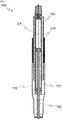
- Figure 1 shows a schematic longitudinal section along a longitudinal axis LA of a standpipe 110 of a column 100 according to the invention.
- the standpipe 110 can, for example, be designed to be rigidly connected with its lower end in the illustration to a foot of a chair.
- a length adjustment device 120 is arranged in the standpipe 110, which device comprises, for example, a piston-cylinder unit.
- the length adjustment device 120 is, for example, rigidly connected to the standpipe 110 at its lower end in the illustration.
- the upper end of the length adjustment device 120 in the illustration can, for example, be designed for rigid connection to a seat surface of a chair.
- the standpipe 110 and the length adjustment device 120 are arranged, for example, essentially cylindrical and coaxially to the longitudinal axis LA.
- the length adjustment device 120 comprises a section 121, for example part of a cylinder housing of a piston-cylinder unit, on the outer surface of which an inner element 140 of a rotation locking device is fastened.
- the inner element 140 is connected to the section 121 by a materially bonded connecting layer (not shown), for example an adhesive layer.
- the inner element 140 In relation to a rotation about the longitudinal axis LA, the inner element 140 interacts in a form-fitting manner with an outer element 130, which is fastened to an inner surface of the standpipe 110, and is guided by the outer element 130 in a displaceable manner along the longitudinal axis LA.
- the inner element 140 and the outer element 130 thus form an anti-rotation device 150 for securing the section 121 against rotation about the longitudinal axis LA relative to the standpipe 110.
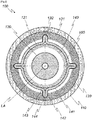
- FIG. 11 shows a schematic cross section orthogonal to the longitudinal axis LA of FIG Figure 1 column 100 shown.
- the cohesive connecting layer 160 between the inner element 140 and the section 121 can be seen.
- the outer element 130 consists of a cylindrical outer base body 131 with a number of, in the illustrated example four, grooves 132 on an inner side. The grooves are in particular spaced apart from one another by 90 ° about the longitudinal axis LA.
- the inner element 140 consists of a cylindrical inner base body 141 with a number of, in the illustrated example four, projections 142 on an outer side consists. The projections 142 engage positively in the grooves 132 with respect to a rotation about the longitudinal axis LA.
- a transition region 143 of the projections 142 to the inner base body 141 and an end 144 of the projections 142 facing away from the inner base body 141 can each, in particular as in FIG Figure 2 shown, be rounded.
- FIG. 11 shows a schematic perspective illustration of the FIG Figure 1 and Figure 2 column 100 shown.
- Figure 4 shows a schematic representation of a method 200 according to the invention.
- the illustrated method 200 comprises providing 210 a length adjustment device 120 with an, in particular cylindrical, section 121 and an, in particular cylindrical, inner element 140 of an anti-rotation device with an inner base body, with an outer diameter of section 121 being smaller or smaller is equal to an inner diameter of the inner base body 141.
- the section 121 and the inner base body 141 are provided, for example, by cold drawing from a steel.
- application 220 for example brushing, of a metal adhesive takes place on an outer surface of section 121.
- the section 121 is arranged 230, in particular coaxially, in the inner main body 141, for example by the section 121 being pushed into the inner main body 141.
- an integral connection 240 of the inner base body 141 to the section 121 for example by curing an adhesive.
Landscapes
- Engineering & Computer Science (AREA)
- General Engineering & Computer Science (AREA)
- Mechanical Engineering (AREA)
- Mutual Connection Of Rods And Tubes (AREA)
Priority Applications (1)
| Application Number | Priority Date | Filing Date | Title |
|---|---|---|---|
| PL18212875T PL3501338T3 (pl) | 2017-12-19 | 2018-12-17 | Kolumna z regulacją długości i sposób jej wytwarzania, mebel |
Applications Claiming Priority (1)
| Application Number | Priority Date | Filing Date | Title |
|---|---|---|---|
| DE102017130473.8A DE102017130473A1 (de) | 2017-12-19 | 2017-12-19 | Längenverstellbare Säule und Herstellungsverfahren dafür, Möbelstück |
Publications (2)
| Publication Number | Publication Date |
|---|---|
| EP3501338A1 EP3501338A1 (de) | 2019-06-26 |
| EP3501338B1 true EP3501338B1 (de) | 2021-06-30 |
Family
ID=64665770
Family Applications (1)
| Application Number | Title | Priority Date | Filing Date |
|---|---|---|---|
| EP18212875.1A Active EP3501338B1 (de) | 2017-12-19 | 2018-12-17 | Längenverstellbare säule und herstellungsverfahren dafür, möbelstück |
Country Status (4)
| Country | Link |
|---|---|
| US (1) | US11009183B2 (pl) |
| EP (1) | EP3501338B1 (pl) |
| DE (1) | DE102017130473A1 (pl) |
| PL (1) | PL3501338T3 (pl) |
Families Citing this family (1)
| Publication number | Priority date | Publication date | Assignee | Title |
|---|---|---|---|---|
| DE102023104261A1 (de) | 2023-02-21 | 2024-08-22 | Accuride International Gmbh | Teleskopschiene mit verbesserter Biegefestigkeit |
Family Cites Families (9)
| Publication number | Priority date | Publication date | Assignee | Title |
|---|---|---|---|---|
| US4613106A (en) * | 1985-04-25 | 1986-09-23 | Tornero Lino E | Mechanical adjustable column |
| DE4313766A1 (de) * | 1993-04-27 | 1994-11-03 | Suspa Compart Ag | Längenverstellbare Säule für Stühle, Tische od. dgl. |
| DE19628721C2 (de) | 1996-07-17 | 1999-01-21 | Stabilus Gmbh | Höhenverstellbare Säule |
| US7134634B2 (en) * | 2001-02-15 | 2006-11-14 | Samhongsa Co., Ltd. | Column unit |
| KR100436415B1 (ko) * | 2001-07-24 | 2004-06-16 | 주식회사 삼홍사 | 칼럼 유니트 및 칼럼 유니트의 튜브 가이드 |
| KR100477072B1 (ko) * | 2002-10-16 | 2005-03-17 | 주식회사 삼홍사 | 칼럼 유니트 |
| CN2785457Y (zh) * | 2005-01-28 | 2006-06-07 | 品赋实业股份有限公司 | 气压伸缩管装置 |
| TR200910119A2 (tr) * | 2009-12-31 | 2011-02-21 | Destek Otomoti̇v Yan Sanayi̇ Ve Ti̇caret Anoni̇m Şi̇rketi̇ | Gazlı yaylarda mil ve borunun dönmesini engelleyen kavrama tertibatı. |
| DE102014108564A1 (de) * | 2014-05-16 | 2014-08-28 | Möbelwerk Ilse GmbH & Co. KG | Tisch |
-
2017
- 2017-12-19 DE DE102017130473.8A patent/DE102017130473A1/de not_active Withdrawn
-
2018
- 2018-12-14 US US16/220,045 patent/US11009183B2/en active Active
- 2018-12-17 EP EP18212875.1A patent/EP3501338B1/de active Active
- 2018-12-17 PL PL18212875T patent/PL3501338T3/pl unknown
Also Published As
| Publication number | Publication date |
|---|---|
| DE102017130473A1 (de) | 2019-06-19 |
| EP3501338A1 (de) | 2019-06-26 |
| US20190186681A1 (en) | 2019-06-20 |
| PL3501338T3 (pl) | 2021-12-27 |
| US11009183B2 (en) | 2021-05-18 |
Similar Documents
| Publication | Publication Date | Title |
|---|---|---|
| DE102013107728B4 (de) | Klemmvorrichtung für eine längsverstellbare und/oder höhenverstellbare Lenksäule eines Fahrzeugs | |
| DE4003245C2 (de) | Führung für teleskopartig ineinander verschiebbare zylindrische Teile | |
| EP3586018B1 (de) | Befestigungsvorrichtung und befestigungsbaugruppe | |
| EP0258656B1 (de) | Teleskopgerät | |
| EP0910318A1 (de) | Federeinrichtung für eine beinprothese | |
| EP0641532B1 (de) | Längenverstellbare Säule für Stühle, Tische o.dgl. | |
| EP2505424A1 (de) | Spindelantrieb für eine Sitzlängsverstellung eines Kraftfahrzeugsitzes | |
| DE102015117049B4 (de) | Armlehne für einen Fahrzeugsitz | |
| DE20207554U1 (de) | Längenverstellbares Rohr, insbesondere für Stöcke | |
| DE10323773A1 (de) | Teleskopauszug | |
| EP0707160B1 (de) | Längenverstellbare Gasfeder für Stühle, Tische o.dgl. | |
| DE102006011491B3 (de) | Höhenverstellbare Stuhlsäule | |
| DE102007017991B4 (de) | Blattfeder aus einem Faser-Kunststoff-Verbundwerkstoff und Krafteinleitungselement für dieselbe | |
| WO2015124466A1 (de) | Zahnstangenlenkung sowie endanschlag-dämpfungsbaugruppe für eine solche zahnstangenlenkung | |
| DE102019103573B4 (de) | Stabilisatoranordnung für ein fahrwerk eines kraftfahrzeugs | |
| DE102009049920A1 (de) | Spannvorrichtung | |
| EP3501338A1 (de) | Längenverstellbare säule und herstellungsverfahren dafür, möbelstück | |
| DE4242475A1 (de) | Führungsbuchse, insbesondere für längenverstellbare Stuhl-Säule und Stuhl-Säule mit derartiger Führungsbuchse | |
| WO2002053933A1 (de) | Kolbenbefestigung | |
| DE10245501A1 (de) | Schaftaufbau mit einer Oberfläche zur Ausbildung von Anschlüssen | |
| EP1650467B1 (de) | Schwingungsdämpfer | |
| EP1846633B1 (de) | Längenverstellbares zwischenstück mit einem unidirektional wirkenden verschiebesperrmechanismus | |
| DE202006001878U1 (de) | Krafteinleitungselement für Faserverbundstreben in Flugzeugen | |
| DE102016210220A1 (de) | Aktuator für eine Hinterachslenkung | |
| DE102024107852B3 (de) | Federstütze für eine Fahrzeugklappe |
Legal Events
| Date | Code | Title | Description |
|---|---|---|---|
| PUAI | Public reference made under article 153(3) epc to a published international application that has entered the european phase |
Free format text: ORIGINAL CODE: 0009012 |
|
| STAA | Information on the status of an ep patent application or granted ep patent |
Free format text: STATUS: THE APPLICATION HAS BEEN PUBLISHED |
|
| AK | Designated contracting states |
Kind code of ref document: A1 Designated state(s): AL AT BE BG CH CY CZ DE DK EE ES FI FR GB GR HR HU IE IS IT LI LT LU LV MC MK MT NL NO PL PT RO RS SE SI SK SM TR |
|
| AX | Request for extension of the european patent |
Extension state: BA ME |
|
| STAA | Information on the status of an ep patent application or granted ep patent |
Free format text: STATUS: REQUEST FOR EXAMINATION WAS MADE |
|
| 17P | Request for examination filed |
Effective date: 20191217 |
|
| RBV | Designated contracting states (corrected) |
Designated state(s): AL AT BE BG CH CY CZ DE DK EE ES FI FR GB GR HR HU IE IS IT LI LT LU LV MC MK MT NL NO PL PT RO RS SE SI SK SM TR |
|
| GRAP | Despatch of communication of intention to grant a patent |
Free format text: ORIGINAL CODE: EPIDOSNIGR1 |
|
| STAA | Information on the status of an ep patent application or granted ep patent |
Free format text: STATUS: GRANT OF PATENT IS INTENDED |
|
| INTG | Intention to grant announced |
Effective date: 20210211 |
|
| GRAJ | Information related to disapproval of communication of intention to grant by the applicant or resumption of examination proceedings by the epo deleted |
Free format text: ORIGINAL CODE: EPIDOSDIGR1 |
|
| GRAL | Information related to payment of fee for publishing/printing deleted |
Free format text: ORIGINAL CODE: EPIDOSDIGR3 |
|
| GRAS | Grant fee paid |
Free format text: ORIGINAL CODE: EPIDOSNIGR3 |
|
| STAA | Information on the status of an ep patent application or granted ep patent |
Free format text: STATUS: REQUEST FOR EXAMINATION WAS MADE |
|
| GRAP | Despatch of communication of intention to grant a patent |
Free format text: ORIGINAL CODE: EPIDOSNIGR1 |
|
| STAA | Information on the status of an ep patent application or granted ep patent |
Free format text: STATUS: GRANT OF PATENT IS INTENDED |
|
| GRAA | (expected) grant |
Free format text: ORIGINAL CODE: 0009210 |
|
| STAA | Information on the status of an ep patent application or granted ep patent |
Free format text: STATUS: THE PATENT HAS BEEN GRANTED |
|
| INTC | Intention to grant announced (deleted) | ||
| INTG | Intention to grant announced |
Effective date: 20210519 |
|
| AK | Designated contracting states |
Kind code of ref document: B1 Designated state(s): AL AT BE BG CH CY CZ DE DK EE ES FI FR GB GR HR HU IE IS IT LI LT LU LV MC MK MT NL NO PL PT RO RS SE SI SK SM TR |
|
| REG | Reference to a national code |
Ref country code: CH Ref legal event code: EP |
|
| REG | Reference to a national code |
Ref country code: AT Ref legal event code: REF Ref document number: 1405526 Country of ref document: AT Kind code of ref document: T Effective date: 20210715 |
|
| REG | Reference to a national code |
Ref country code: DE Ref legal event code: R096 Ref document number: 502018005904 Country of ref document: DE |
|
| REG | Reference to a national code |
Ref country code: IE Ref legal event code: FG4D Free format text: LANGUAGE OF EP DOCUMENT: GERMAN |
|
| REG | Reference to a national code |
Ref country code: NO Ref legal event code: T2 Effective date: 20210630 |
|
| REG | Reference to a national code |
Ref country code: SE Ref legal event code: TRGR |
|
| REG | Reference to a national code |
Ref country code: LT Ref legal event code: MG9D |
|
| PG25 | Lapsed in a contracting state [announced via postgrant information from national office to epo] |
Ref country code: BG Free format text: LAPSE BECAUSE OF FAILURE TO SUBMIT A TRANSLATION OF THE DESCRIPTION OR TO PAY THE FEE WITHIN THE PRESCRIBED TIME-LIMIT Effective date: 20210930 Ref country code: FI Free format text: LAPSE BECAUSE OF FAILURE TO SUBMIT A TRANSLATION OF THE DESCRIPTION OR TO PAY THE FEE WITHIN THE PRESCRIBED TIME-LIMIT Effective date: 20210630 Ref country code: HR Free format text: LAPSE BECAUSE OF FAILURE TO SUBMIT A TRANSLATION OF THE DESCRIPTION OR TO PAY THE FEE WITHIN THE PRESCRIBED TIME-LIMIT Effective date: 20210630 |
|
| PG25 | Lapsed in a contracting state [announced via postgrant information from national office to epo] |
Ref country code: RS Free format text: LAPSE BECAUSE OF FAILURE TO SUBMIT A TRANSLATION OF THE DESCRIPTION OR TO PAY THE FEE WITHIN THE PRESCRIBED TIME-LIMIT Effective date: 20210630 Ref country code: LV Free format text: LAPSE BECAUSE OF FAILURE TO SUBMIT A TRANSLATION OF THE DESCRIPTION OR TO PAY THE FEE WITHIN THE PRESCRIBED TIME-LIMIT Effective date: 20210630 Ref country code: GR Free format text: LAPSE BECAUSE OF FAILURE TO SUBMIT A TRANSLATION OF THE DESCRIPTION OR TO PAY THE FEE WITHIN THE PRESCRIBED TIME-LIMIT Effective date: 20211001 |
|
| REG | Reference to a national code |
Ref country code: NL Ref legal event code: FP |
|
| PG25 | Lapsed in a contracting state [announced via postgrant information from national office to epo] |
Ref country code: SM Free format text: LAPSE BECAUSE OF FAILURE TO SUBMIT A TRANSLATION OF THE DESCRIPTION OR TO PAY THE FEE WITHIN THE PRESCRIBED TIME-LIMIT Effective date: 20210630 Ref country code: SK Free format text: LAPSE BECAUSE OF FAILURE TO SUBMIT A TRANSLATION OF THE DESCRIPTION OR TO PAY THE FEE WITHIN THE PRESCRIBED TIME-LIMIT Effective date: 20210630 Ref country code: EE Free format text: LAPSE BECAUSE OF FAILURE TO SUBMIT A TRANSLATION OF THE DESCRIPTION OR TO PAY THE FEE WITHIN THE PRESCRIBED TIME-LIMIT Effective date: 20210630 Ref country code: ES Free format text: LAPSE BECAUSE OF FAILURE TO SUBMIT A TRANSLATION OF THE DESCRIPTION OR TO PAY THE FEE WITHIN THE PRESCRIBED TIME-LIMIT Effective date: 20210630 Ref country code: CZ Free format text: LAPSE BECAUSE OF FAILURE TO SUBMIT A TRANSLATION OF THE DESCRIPTION OR TO PAY THE FEE WITHIN THE PRESCRIBED TIME-LIMIT Effective date: 20210630 Ref country code: PT Free format text: LAPSE BECAUSE OF FAILURE TO SUBMIT A TRANSLATION OF THE DESCRIPTION OR TO PAY THE FEE WITHIN THE PRESCRIBED TIME-LIMIT Effective date: 20211102 Ref country code: RO Free format text: LAPSE BECAUSE OF FAILURE TO SUBMIT A TRANSLATION OF THE DESCRIPTION OR TO PAY THE FEE WITHIN THE PRESCRIBED TIME-LIMIT Effective date: 20210630 |
|
| REG | Reference to a national code |
Ref country code: DE Ref legal event code: R097 Ref document number: 502018005904 Country of ref document: DE |
|
| PG25 | Lapsed in a contracting state [announced via postgrant information from national office to epo] |
Ref country code: DK Free format text: LAPSE BECAUSE OF FAILURE TO SUBMIT A TRANSLATION OF THE DESCRIPTION OR TO PAY THE FEE WITHIN THE PRESCRIBED TIME-LIMIT Effective date: 20210630 |
|
| PLBE | No opposition filed within time limit |
Free format text: ORIGINAL CODE: 0009261 |
|
| STAA | Information on the status of an ep patent application or granted ep patent |
Free format text: STATUS: NO OPPOSITION FILED WITHIN TIME LIMIT |
|
| PG25 | Lapsed in a contracting state [announced via postgrant information from national office to epo] |
Ref country code: AL Free format text: LAPSE BECAUSE OF FAILURE TO SUBMIT A TRANSLATION OF THE DESCRIPTION OR TO PAY THE FEE WITHIN THE PRESCRIBED TIME-LIMIT Effective date: 20210630 |
|
| 26N | No opposition filed |
Effective date: 20220331 |
|
| PG25 | Lapsed in a contracting state [announced via postgrant information from national office to epo] |
Ref country code: MC Free format text: LAPSE BECAUSE OF FAILURE TO SUBMIT A TRANSLATION OF THE DESCRIPTION OR TO PAY THE FEE WITHIN THE PRESCRIBED TIME-LIMIT Effective date: 20210630 |
|
| REG | Reference to a national code |
Ref country code: BE Ref legal event code: MM Effective date: 20211231 |
|
| PG25 | Lapsed in a contracting state [announced via postgrant information from national office to epo] |
Ref country code: LU Free format text: LAPSE BECAUSE OF NON-PAYMENT OF DUE FEES Effective date: 20211217 Ref country code: IE Free format text: LAPSE BECAUSE OF NON-PAYMENT OF DUE FEES Effective date: 20211217 |
|
| PG25 | Lapsed in a contracting state [announced via postgrant information from national office to epo] |
Ref country code: BE Free format text: LAPSE BECAUSE OF NON-PAYMENT OF DUE FEES Effective date: 20211231 |
|
| PG25 | Lapsed in a contracting state [announced via postgrant information from national office to epo] |
Ref country code: LT Free format text: LAPSE BECAUSE OF FAILURE TO SUBMIT A TRANSLATION OF THE DESCRIPTION OR TO PAY THE FEE WITHIN THE PRESCRIBED TIME-LIMIT Effective date: 20210630 |
|
| P01 | Opt-out of the competence of the unified patent court (upc) registered |
Effective date: 20230510 |
|
| PG25 | Lapsed in a contracting state [announced via postgrant information from national office to epo] |
Ref country code: CY Free format text: LAPSE BECAUSE OF FAILURE TO SUBMIT A TRANSLATION OF THE DESCRIPTION OR TO PAY THE FEE WITHIN THE PRESCRIBED TIME-LIMIT Effective date: 20210630 |
|
| PG25 | Lapsed in a contracting state [announced via postgrant information from national office to epo] |
Ref country code: HU Free format text: LAPSE BECAUSE OF FAILURE TO SUBMIT A TRANSLATION OF THE DESCRIPTION OR TO PAY THE FEE WITHIN THE PRESCRIBED TIME-LIMIT; INVALID AB INITIO Effective date: 20181217 |
|
| PG25 | Lapsed in a contracting state [announced via postgrant information from national office to epo] |
Ref country code: MK Free format text: LAPSE BECAUSE OF FAILURE TO SUBMIT A TRANSLATION OF THE DESCRIPTION OR TO PAY THE FEE WITHIN THE PRESCRIBED TIME-LIMIT Effective date: 20210630 |
|
| PG25 | Lapsed in a contracting state [announced via postgrant information from national office to epo] |
Ref country code: MT Free format text: LAPSE BECAUSE OF FAILURE TO SUBMIT A TRANSLATION OF THE DESCRIPTION OR TO PAY THE FEE WITHIN THE PRESCRIBED TIME-LIMIT Effective date: 20210630 |
|
| REG | Reference to a national code |
Ref country code: AT Ref legal event code: MM01 Ref document number: 1405526 Country of ref document: AT Kind code of ref document: T Effective date: 20231217 |
|
| PG25 | Lapsed in a contracting state [announced via postgrant information from national office to epo] |
Ref country code: AT Free format text: LAPSE BECAUSE OF NON-PAYMENT OF DUE FEES Effective date: 20231217 |
|
| PG25 | Lapsed in a contracting state [announced via postgrant information from national office to epo] |
Ref country code: TR Free format text: LAPSE BECAUSE OF FAILURE TO SUBMIT A TRANSLATION OF THE DESCRIPTION OR TO PAY THE FEE WITHIN THE PRESCRIBED TIME-LIMIT Effective date: 20210630 |
|
| REG | Reference to a national code |
Ref country code: CH Ref legal event code: U11 Free format text: ST27 STATUS EVENT CODE: U-0-0-U10-U11 (AS PROVIDED BY THE NATIONAL OFFICE) Effective date: 20260101 |
|
| PGFP | Annual fee paid to national office [announced via postgrant information from national office to epo] |
Ref country code: DE Payment date: 20251211 Year of fee payment: 8 |
|
| PGFP | Annual fee paid to national office [announced via postgrant information from national office to epo] |
Ref country code: GB Payment date: 20251219 Year of fee payment: 8 |
|
| PGFP | Annual fee paid to national office [announced via postgrant information from national office to epo] |
Ref country code: IT Payment date: 20251223 Year of fee payment: 8 |
|
| PGFP | Annual fee paid to national office [announced via postgrant information from national office to epo] |
Ref country code: NL Payment date: 20251219 Year of fee payment: 8 Ref country code: FR Payment date: 20251229 Year of fee payment: 8 |
|
| PGFP | Annual fee paid to national office [announced via postgrant information from national office to epo] |
Ref country code: SE Payment date: 20251219 Year of fee payment: 8 |
|
| PGFP | Annual fee paid to national office [announced via postgrant information from national office to epo] |
Ref country code: PL Payment date: 20251205 Year of fee payment: 8 |
|
| PGFP | Annual fee paid to national office [announced via postgrant information from national office to epo] |
Ref country code: NO Payment date: 20251230 Year of fee payment: 8 |
|
| PGFP | Annual fee paid to national office [announced via postgrant information from national office to epo] |
Ref country code: AT Payment date: 20260410 Year of fee payment: 5 |
|
| PGFP | Annual fee paid to national office [announced via postgrant information from national office to epo] |
Ref country code: CH Payment date: 20260101 Year of fee payment: 8 |