EP3501310A2 - Heizvorrichtung, zerstäuber und elektronische zigarette damit - Google Patents
Heizvorrichtung, zerstäuber und elektronische zigarette damit Download PDFInfo
- Publication number
- EP3501310A2 EP3501310A2 EP19163441.9A EP19163441A EP3501310A2 EP 3501310 A2 EP3501310 A2 EP 3501310A2 EP 19163441 A EP19163441 A EP 19163441A EP 3501310 A2 EP3501310 A2 EP 3501310A2
- Authority
- EP
- European Patent Office
- Prior art keywords
- liquid conductive
- liquid
- heating device
- conductive body
- annular
- Prior art date
- Legal status (The legal status is an assumption and is not a legal conclusion. Google has not performed a legal analysis and makes no representation as to the accuracy of the status listed.)
- Granted
Links
Images



Classifications
-
- A—HUMAN NECESSITIES
- A24—TOBACCO; CIGARS; CIGARETTES; SIMULATED SMOKING DEVICES; SMOKERS' REQUISITES
- A24F—SMOKERS' REQUISITES; MATCH BOXES; SIMULATED SMOKING DEVICES
- A24F40/00—Electrically operated smoking devices; Component parts thereof; Manufacture thereof; Maintenance or testing thereof; Charging means specially adapted therefor
- A24F40/40—Constructional details, e.g. connection of cartridges and battery parts
- A24F40/46—Shape or structure of electric heating means
-
- A—HUMAN NECESSITIES
- A24—TOBACCO; CIGARS; CIGARETTES; SIMULATED SMOKING DEVICES; SMOKERS' REQUISITES
- A24F—SMOKERS' REQUISITES; MATCH BOXES; SIMULATED SMOKING DEVICES
- A24F40/00—Electrically operated smoking devices; Component parts thereof; Manufacture thereof; Maintenance or testing thereof; Charging means specially adapted therefor
- A24F40/40—Constructional details, e.g. connection of cartridges and battery parts
- A24F40/44—Wicks
-
- A—HUMAN NECESSITIES
- A24—TOBACCO; CIGARS; CIGARETTES; SIMULATED SMOKING DEVICES; SMOKERS' REQUISITES
- A24F—SMOKERS' REQUISITES; MATCH BOXES; SIMULATED SMOKING DEVICES
- A24F40/00—Electrically operated smoking devices; Component parts thereof; Manufacture thereof; Maintenance or testing thereof; Charging means specially adapted therefor
- A24F40/10—Devices using liquid inhalable precursors
Definitions
- the present disclosure relates to the field of electronic cigarettes, and particularly to a heating device, an atomizer and an electronic cigarette having same.
- the electronic cigarettes containing tobacco liquid generates an aerosol mainly by a heating device heating the tobacco liquid, of which, the heating device mainly includes a liquid conductive body and a heating element; the tobacco liquid is transmitted via the liquid conductive body into the heating element for heated.
- the liquid conductive body is generally formed by winding multiple layers of non-woven fabrics.
- inventors are difficult to control a thickness of the liquid conductive body.
- the more thick the liquid conductive body the more hardship it has for being installed into a shell with a fixed size. If the liquid conductive body itself is too thin, after it has been installed into the shell, a seam is emerged between the liquid conductive body and the shell, resulting in leakage of the tobacco liquid, therefore deteriorating the yield of electronic cigarettes over time, exerting a detrimental influence such as low efficiency on automatic production over time.
- the present disclosure relates to a heating device, an atomizer and an electronic cigarette having the same, which are capable of improving the yield of electronic cigarettes over time, and exerting a beneficial influence such high efficiency on automatic production over time.
- a heating device includes: a shell, with a receiving chamber formed therein; a heating element, received in the receiving chamber to contact with a liquid conductive body; the liquid conductive body, configured for absorbing tobacco liquid and supplying the tobacco liquid to the heating element; the liquid conductive body includes multiple annular liquid conductive layers stacked inside the shell, along an axial direction of the shell; outer diameters of the multiple annular liquid conductive layers are equal to an inner diameter of the receiving chamber such that the multiple annular liquid conductive layers are capable of being received in the receiving chamber and abutting against an inner surface of the shell.
- the annular liquid conductive layers are annular non-woven fabrics, and each annular non-woven fabric includes an air hole, multiple air holes of multiple non-woven fabrics intercommunicate to emerge as a first air passage extending an axial direction of the shell.
- the heating element is a heating coil.
- the heating coil is disposed inside the first air passage.
- the heating element is a disk-shaped heating piece with a third air hole thereon.
- the annular non-woven fabrics at least include a first annular non-woven fabric and a second annular non-woven fabric.
- the disk-shaped heating piece is clamped between the first annular non-woven fabric and the second annular non-woven fabric, and the third air hole is communicated with the first air passage.
- a liquid conductive hole is bored on a sidewall of the shell.
- the liquid conductive hole contacts with the liquid conductive body and is configured for supplying tobacco liquid to the liquid conductive body.
- the heating device further includes: a compression member; the compression member is mounted in the mounting hole and abuts against one end of the liquid conductive body, configured for compressing the liquid conductive body to adjust a volume of the liquid conductive body.
- the shell further includes: an annular stopper;
- the annular stopper is disposed inside the receiving chamber, one end of the liquid conductive body abuts against the annular stopper, and an opposite end thereof abuts against the compression member; the first air hole is corresponding with a central hole of the annular stopper.
- the heating device further includes: a filtering net; the filtering net is disposed between the liquid conductive body and the annular stopper, corresponding with the annular non-woven fabrics, the filtering net is configured for preventing the tobacco liquid from flowing into the first through hole.
- the heating device further includes: an anode ring; the anode ring is connected with the compression member.
- an atomizer includes a case and the aforementioned heating device; the case has a liquid storage chamber formed therein; the heating device is received in the case, such that the heating device is capable of receiving tobacco liquid from the liquid storage chamber and heating the tobacco liquid.
- an electronic cigarette including: a power supply module and the aforementioned atomizer; the atomizer is coupled with the power supply module via the heating element.
- the present disclosure relates to a heating device, an atomizer and an electronic cigarette having same.
- the heating device includes: a shell, a heating element and a liquid conductive body.
- the shell has a receiving chamber formed therein.
- the heating element is received in the receiving chamber and contacts with the liquid conductive body.
- the liquid conductive body is configured for absorbing tobacco liquid and supplying the tobacco liquid to the heating element.
- the liquid conductive body includes multiple annular liquid conductive layer stacked inside the shell along an axial direction of the shell, by making the outer diameter of multiple annular liquid conductive layers equal to the inner diameter of the receiving chamber, the annular liquid conductive layers are capable to be received in the receiving chamber and abut against the inner wall of the shell, which reduces the phenomenon that the liquid conductive body is too thick or too thin, resulting in improving the yield of the electronic cigarettes over time and improving production efficiency.
- 1 represents the heating device
- 10 represents the shell
- 11 represents the receiving chamber
- 12 represents the liquid conductive hole
- 13 represents the first air hole
- 14 represents the mounting hole
- 15 represents the clamping part
- 16 represents the annular stopper
- 161 represents the central hole
- 20 represents the liquid conductive body
- 21 represents the annular non-woven fabrics
- 21a represents the first annular non-woven fabrics
- 21b represents the second annular non-woven fabrics
- 211 represents the air hole
- 22 represents the first air pipe
- 30 represents the heating element
- 31 represents the anode terminal
- 32 represents the cathode terminal
- 33 represents the second air hole
- 34 represents the third air hole
- 40 represents the compression member
- 41 represents the compression main body
- 42 represents the connecting part
- 43 represents the compression part
- 44 represents the receiving hole
- 50 represents the filtering net
- 60 represents the cathode ring
- 61 represents the cathode main ring
- 611 represents the airflow hole
- 62 represents the
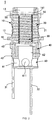
- the heating device 1 applied to the atomizer, including: a shell 10, a liquid conductive body 20, a heating element 30, a compression part 40, a filtering net 50 and a cathode ring 60.
- the shell 10 is a tube-shaped structure in rotational symmetry.
- a cross-section of the receiving chamber 11 is round to be coaxial with the shell 10.
- the cross-section of the receiving chamber 11 is rectangular or other polygonal.
- first air hole 13 Two ends of the shell 10 are respectively bored with a first air hole 13 and a mounting hole 14, both intercommunicate with the receiving chamber 11, and the first air hole 13, the mounting hole 14 and the receiving chamber 11 are coaxial with each other, in which, a diameter of the first air hole 13 is less than that of the receiving chamber 11, the diameter of the mounting hole 14 is equal to that of the receiving chamber 11.
- the diameter of the first air hole 13 is also equal to that of the receiving chamber 11.
- the sidewall of the shell 10 is also bored with multiple of the liquid conductive holes 12.
- the liquid conductive holes 12 are posited around the shell 10 symmetrically. Exterior tobacco liquid of the heating device 1 through the liquid conductive holes 12 flow into the heating device 1 for being heated to generate an aerosol.
- the number of the liquid conductive holes 12 is four which allows the tobacco liquid to evenly flow into the heating device 1.
- the sidewall of the shell 10 protrudes to form a clamping part 15, the clamping part 15 is located below the liquid conductive holes 12, emerging as a continuous protrusion.
- the clamping part 15 may be made of multiple of protrusions, posited around the shell 10 symmetrically.
- the shell 10 includes an annular stopper 16, the annular stopper 16 is posited closer to an end of the first air hole 13.
- the central hole 161 of the annular stopper 16 is corresponding with the first air hole 13.
- the liquid conductive body 20, the heating element 30 and the filtering net 50 are all received in the receiving chamber 11, in which, an end of the liquid conductive body 20 is passing through the filtering net 50 to abut against the annular stopper 16. Moreover, when the liquid conductive body 20 is received in the receiving chamber 11, the liquid conductive body 20 contacts the liquid conductive holes 12, enabling exterior tobacco liquid of the heating device 1 to pass through the liquid conductive holes12, flowing into the liquid conductive body 20 and temporally stored in the liquid conductive body 20, eventually transmitted to the heating element 30 for heating to generate an aerosol.
- the compression member 40 is mounted in the mounting hole 14 of the shell 10, abutting against an opposite end of the liquid conductive body 20 to compress the liquid conductive body 20 so as to adjust the volume of the liquid conductive body 20.
- the liquid conductive body 20 is in a comparatively loose state.
- just mounting the compression member 40 into the mounting hole 14 can finish the compression of the liquid conductive body 20, which can simplify the assembling process of the liquid conductive body 20 to realize rapid assembly.
- the assembling of the liquid conductive body 20 can be finished in automation equipment, which is beneficial for automation production and improving the efficiency thereof.
- the cathode ring 60 is connected with the compression member 40.
- the liquid conductive body 20 is configured for absorbing tobacco liquid and supplying the tobacco liquid to the heating element 30, made of multiple annular liquid conductive layers stacked along an axial direction of the shell 10.
- the annular liquid conductive layers may be made by organic cottons, man-made fiber cottons, non-woven fabrics or micro polymer foam materials etc. More specifically, in the embodiment, the annular liquid conductive layer is formed by compressing annular non-woven fabrics 21 to a blocky-shape, in which, the middle of the annular non-woven fabrics 21 is bored with the air hole 211.
- the air hole 211 of each non-woven fabric 21 intercommunicates with each other to emerge as the first air pipe 22 along an axial direction of the shell 10.
- the first air pipe 22 intercommunicate with the first air hole 13 and the mounting hole 14.
- the outer diameter of the non-woven fabrics 21 is equal to the inner diameter of the receiving chamber 11, making the liquid conductive body 20 available of being received in the receiving chamber 11, and making the liquid conductive body 20 available of abutting against the liquid conductive holes 12 so the tobacco liquid may flow into the liquid conductive body 20 better, as well as reducing the phenomenon of tobacco liquid leakage and improve yield of the electronic cigarette production. Meanwhile, by stacking the non-woven fabrics 21 in fixed dimension, a liquid conductive body 20 is formed which is beneficial for automation production and improving the production efficiency.
- the tightness of the compressed liquid conductive body 20 is related to the number of the non-woven fabrics 21. Under the circumstance that a space between the compression member 40 and the receiving chamber 11 is fixed, the more the number of the non-woven fabrics 21, the tighter the liquid conductive body 20 becomes after compressed by the compression member 40. Due to the compression effect of the compression member 40, close contact among adjacent layers of non-woven fabrics 21 may prevent the tobacco liquid leaking through adjacent layers of non-woven fabrics 21.
- each circular non-woven fabric 21 is successively loaded into the receiving chamber 11 of the shell 10, then the compression member 40 is loaded into the mounting hole 14, and the circular non-woven fabrics 21 are compressed into the receiving chamber 11, to fulfill the assembly of the liquid conductive body 20.
- the heating element 30 is a spiral heating coil that is made by winding a set of one or two or even more metal heating wire.
- the heating coil is made by winding two heating wires to a spiral shape, and adjacent heating wire sets have an equipollent distance.
- the metal heating wire is made by Nickel, Iron-Nickel alloy or Iron-Chromium-Aluminum alloys.
- the heating coil is other singular heating wire with comparatively high electric resistivity and may be made by loosely winding, making the heating power comparatively small.
- the heating coil is disposed in the first air pipe 22 of the liquid conductive body 20, surrounded by the liquid conductive body 20.
- the liquid conductive body 20 conducts the tobacco liquid to the heating coil for heating to generate an aerosol.
- the outer diameter of the heating coil is equal to the diameter of the first air pipe 22, making the heating coil to contact with the liquid conductive body 20, which is beneficial for the heating coil to heat the tobacco liquid in the liquid conductive body 20.
- a second air hole 33 is bored at a middle of the heating coil, the second air hole 33 and the first air hole 13 intercommunicate with the mounting hole 14.
- the aerosol generated by the heating coil flows from the second air hole 33 to the first air hole 13, drawn by the user through the first air hole 13.
- the heating coil further includes an anode terminal 31 and a cathode terminal 32, the anode terminal 31 and the cathode terminal 32 are coupled with the power supply to make the heating coil working.
- the compression member 40 includes a compression main body 41 having a tube-shaped structure, with a receiving hole 44 formed at a central part thereof.
- An end of an outer wall of the compression main body 41 protrudes to form a connecting part 42, an outer diameter of the connecting part 42 is equal to an outer diameter of the shell 10.
- An opposite end of the outer wall of the compression main body 41 protrudes to form a compression part 43, an outer diameter of the compression part 43 is equal to an inner diameter of the shell 10.
- the compression member 40 is entirely loaded into the mounting hole 14, at that time, the connecting part 42 abuts against a bottom of the shell 10.
- the connecting part 42 abuts against a bottom of the shell 10.
- the compression member 40 is made by insulation materials, which may be a rubber ring configured for separating the anode terminal 31 from the cathode terminal 32.
- the axis of the receiving hole 44 is coaxial with the receiving chamber 11. Moreover, the anode terminal 31 of the heating coil is disposed outside the compression member 40, and the cathode terminal 32 is disposed inside the receiving hole 44.
- a plug may be added between the compression member 40 and the liquid conductive body 20 to compress the volume of the liquid conductive body 20.
- the shape of the filtering net 50 is the same as the shape of the non-woven fabric 21, the filtering net 50 is disposed between the liquid conductive body 20 and the circular stopper 16.
- the diameter of the central hole of the circular stopper 16 is larger than the diameter of the first air pipe 22, it can prevent tobacco liquid from flowing to the first air hole 13 via the central hole 161, which effectively avoids the user to draw the tobacco liquid from the first air hole 13.
- the cathode ring 60 includes a cathode main ring 61, the cathode main ring 61 is a tube-shaped structure, a diameter thereof is larger than a diameter of the receiving hole 44 and less than an outer diameter of the connecting part 42 of the compression member 40.
- a cavity (not shown) is formed inside the cathode main ring 61.
- a side wall of the cathode main ring 61 has an airflow hole 611, the airflow holes 611 are bored around the cathode main ring 61 symmetrically, intercommunicating with the cavity, allowing exterior air to flow into the cavity.
- the number of the airflow holes 611 is four, which may allow exterior air to flow into the cavity.
- An upper surface of the cathode main ring 61 extends upwards emerging as an extending part (not shown), a diameter of the extending part is less than a diameter of the cathode main ring 61, in this case, a first connecting part is formed on the cathode main ring 61, the cathode ring 60 is fixed with the compression member 40 via the first connecting part.
- the diameter of the extending part is less than that of the receiving hole 44, so when the cathode ring 60 is connected with the compression member 40, the extending part is properly received in the receiving hole 44.
- a central of the extending part is provided with a second air pipe 62, the second air pipe 62 intercommunicates with the cavity.
- the cathode terminal 32 of the heating coil is connected with the cathode ring 60.
- the cathode terminal 32 of the heating coil is electrically connected with the cathode terminal of the power supply.
- the second air pipe 62 is corresponding with the first air pipe 22, the airflow holes 611, the cavity, the second air pipe 62, the second air hole 33 and the first air hole 13 come to be an air passage.
- the diameter of the extending part is equal to the diameter of the receiving hole 44, when the cathode ring 60 is connected with the compression member 40, the extending part is rivet connected with the receiving hole 44.
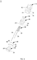
- the heating device 1 when the heating device 1 is assembled, firstly assembling the heating coil into the receiving chamber 11 of the shell 10, the second air hole 33 of the heating coil is coaxial with the first air hole 13; secondly, assembling the filtering net 50 in the receiving chamber 11 via the mounting hole 14 then the filtering net 50 is sleeved on the heating coil, meanwhile, the filtering net 50 abuts against the annular stopper 16; next, assembling each non-woven fabric 21 into the receiving chamber 11 through the mounting hole 14 that the non-woven fabrics 21 are sleeved on the heating coil; then assembling the compression member 40 into the mounting hole 14, the compression part 43 of the compression member 40 is assembled into the liquid conductive body 20 that is made by annular non-woven fabrics 21 in the receiving chamber 11, the connecting part 42 of the compression member 40 abuts against the bottom of the shell 10;meanwhile, one end of the liquid conductive body 20 abuts against the filtering net 50, an opposite end of the liquid conductive body 20 abuts against the compression member 40, and
- the heating device includes: a shell, a heating element and a liquid conductive body.
- the shell has a receiving chamber formed therein.
- the heating element is received in the receiving chamber and contacts with the liquid conductive body.
- the liquid conductive body is configured for absorbing tobacco liquid and supplying the tobacco liquid to the heating element.
- the liquid conductive body includes multiple annular liquid conductive layers stacked inside the shell along an axial direction of the shell, by making the outer diameter of multiple annular liquid conductive layers equal to the inner diameter of the receiving chamber, the annular liquid conductive layers are capable to be received in the receiving chamber and abut against the inner wall of the shell, which reduces the phenomenon that the liquid conductive body is too thick or too thin, resulting in improving the yield of the electronic cigarettes over time. And the method of manufacturing the liquid conductive body by stacking non-woven fabrics in fixed size is beneficial for automatic production, thus improving production efficiency.
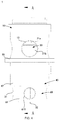
- FIG. 4 to FIG. 6 which are structural views of the heating device in accordance with embodiments of the present disclosure.
- the heating device 1 is basically the same as Embodiment 1, the same technical schemes refer to Embodiment 1, no description hereinafter.
- the differential points are that the heating element 30 is a disk-shaped heating piece, the circular non-woven fabrics 21 at least includes a first circular non-woven fabric 21a and a second circular non-woven fabric 21b, the disk-shaped heating piece is clamped between the first circular non-woven fabric 21a and the second circular non-woven fabric 21b.
- the first circular non-woven fabric 21a is a non-woven fabric with comparatively good tobacco liquid conductivity, which is received in an end of the receiving chamber 11 closer to the first air hole 13.
- the second circular non-woven fabric 21b is a non-woven fabric with comparatively good tobacco liquid conductivity, which is received in an end of the receiving chamber 11 closer to the mounting hole 14, thus effectively avoiding the leakage of tobacco liquid.
- the number of the first circular non-woven fabrics 21a is the same as the number of the second circular non-woven fabrics 21b, thus when the disk-shaped heating piece is clamped between the first circular non-woven fabrics 21a and the second circular non-woven fabrics 21b, the disk-shaped heating piece is at the middle of the liquid conductive body 20.
- the number of the first circular non-woven fabrics 21a may be different from the number of the second circular non-woven fabrics 21b.
- the disk-shaped heating piece is disk-shaped ceramic heating piece, an outer diameter thereof is less than an outer diameter of the non-woven fabric 20.
- a third air hole 34 is bored at a central of the disk-shaped heating piece.
- each annular heating slot includes two heating slots (not shown), both are disposed symmetrically.
- Multiple sets of annular heating slots are concentric along the third air hole 34. The diameters thereof are gradually increasing away from the third air hole 34, and adjacent sets of circular heating slots are staggered with each other to 90 degree, which may enlarge the heating area of the disk-shaped heating piece, meanwhile, making the disk-shaped heating piece heat even.
- the disk-shaped heating piece further includes an anode terminal 31 and a cathode terminal 32, the cathode terminal 32 is disposed on inside wall of the third air hole 34.
- the anode terminal 31 is disposed on outside wall of the disk-shaped heating piece, enabling the anode terminal 31 and the cathode terminal 32 to be separated by the compression member 40.
- the third air hole 34 has the same diameter with the first air pipe 22.
- the disk-shaped heating piece When the disk-shaped heating piece is clamped between the first annular non-woven fabric 21a and the second annular non-woven fabric 21b, the third air hole 34 is corresponding with the first air pipe 22.
- the disk-shaped heating piece heats the tobacco liquid to generate an aerosol passing through the third air hole 34 and entering into the first air pipe 22, then flowing into the first air hole 13 via the first air pipe 22, eventually drawn by the user from the first air pipe 22.
- the heating device 1 when the heating device 1 is assembled, firstly assembling the filtering net 50 into the receiving chamber 11 from the mounting hole 14, at this time the filtering net 50 abuts against the annular stopper 16; then assembling each first annular non-woven fabrics 21a to the receiving chamber 11 from the mounting hole 14; afterwards assembling the disk-shaped heating piece into the receiving chamber 11 from the mounting hole 14 such that the third air hole 34 is corresponding with the first air pipe 22; then assembling the second circular non-woven fabrics 21b successively to the receiving chamber 11 from the mounting hole 14; and then assembling the compression member 40 into the mounting hole 14, the compression part 43 of the compression member 40 compresses the second annular non-woven fabrics 21b in the receiving chamber 11 to form a desired volume of the liquid conductive body 20, the connecting part 42 of the compression member 40 abuts against the bottom of the shell 10, at this time, an end of the liquid conductive body 20, that is the first annular non-woven fabric 21a, abuts against the filtering net 50; and an opposite end of the liquid
- the cathode terminal 32 of the disk-shaped heating piece is connected with a cathode main ring 61 via the first air pipe 22, the second air pipe 62 and the cathode main ring 61 to finish the assembling of the heating device 1.
- the heating device includes: a shell, a heating element and a liquid conductive body.
- the shell has a receiving chamber formed therein.
- the heating element is received in the receiving chamber and contacts with the liquid conductive body.
- the liquid conductive body is configured for absorbing tobacco liquid and supplying the tobacco liquid to the heating element.
- the liquid conductive body includes multiple annular liquid conductive layers stacked inside the shell along an axial direction of the shell, by making the outer diameter of multiple annular liquid conductive layers equal to the inner diameter of the receiving chamber, the annular liquid conductive layers are capable to be stacked in the receiving chamber and abut against the inner wall of the shell, which reduces the phenomenon that the liquid conductive body is too thick or too thin, resulting in improving the yield of the electronic cigarettes over time. And the method of manufacturing the liquid conductive body by stacking non-woven fabrics in fixed size is beneficial for automatic production, thus improving production efficiency.
- an atomizer in accordance with embodiments of the present disclosure, is disclosed, the atomizer (not shown) includes a case (not shown) and the aforementioned heating device 1, the heating device 1 is received in the case and fixedly connected with the case.
- the case and the clamping part 15 of the shell 10 of the heating device 1 are sealed with a sealing ring.
- the case has a liquid storage chamber formed therein, the heating device 1 is received in the case and is capable to obtain tobacco liquid for heating.
- the liquid storage chamber may also be disposed around a periphery of the heating device 1, in some embodiments, the liquid storage chamber is at the upper or lower of the heating device.
- an electronic cigarette in accordance with embodiments of the present disclosure, includes a power supply module (not shown) and the aforementioned atomizer (not shown).
- a cathode terminal of the power supply module contacts the cathode ring 60 of the atomizer.
- An anode terminal of the power supply module is electrically connected with the anode terminal 31 of the heating element 30.
Landscapes
- Resistance Heating (AREA)
Applications Claiming Priority (1)
| Application Number | Priority Date | Filing Date | Title |
|---|---|---|---|
| CN201820365263.6U CN208192137U (zh) | 2018-03-16 | 2018-03-16 | 一种加热装置、雾化器及电子烟 |
Publications (3)
| Publication Number | Publication Date |
|---|---|
| EP3501310A2 true EP3501310A2 (de) | 2019-06-26 |
| EP3501310A3 EP3501310A3 (de) | 2019-08-28 |
| EP3501310B1 EP3501310B1 (de) | 2021-08-25 |
Family
ID=64527078
Family Applications (1)
| Application Number | Title | Priority Date | Filing Date |
|---|---|---|---|
| EP19163441.9A Active EP3501310B1 (de) | 2018-03-16 | 2019-03-18 | Heizvorrichtung, zerstäuber und elektronische zigarette damit |
Country Status (3)
| Country | Link |
|---|---|
| US (1) | US11096425B2 (de) |
| EP (1) | EP3501310B1 (de) |
| CN (1) | CN208192137U (de) |
Cited By (1)
| Publication number | Priority date | Publication date | Assignee | Title |
|---|---|---|---|---|
| CN113633024A (zh) * | 2021-08-20 | 2021-11-12 | 深圳市美深瑞科技有限公司 | 雾化器及电子雾化装置 |
Families Citing this family (3)
| Publication number | Priority date | Publication date | Assignee | Title |
|---|---|---|---|---|
| CN110558632B (zh) * | 2019-10-23 | 2024-06-14 | 深圳市你我网络科技有限公司 | 一种雾化器及电子烟 |
| USD927058S1 (en) * | 2019-11-29 | 2021-08-03 | Tuanfang Liu | Atomizing core for electronic cigarette |
| US11988377B2 (en) * | 2020-11-26 | 2024-05-21 | Aspire North America Llc | Heating element |
Family Cites Families (29)
| Publication number | Priority date | Publication date | Assignee | Title |
|---|---|---|---|---|
| CN202618275U (zh) | 2012-04-01 | 2012-12-26 | 惠州市吉瑞科技有限公司 | 电子烟及其吸嘴 |
| RU2674714C2 (ru) | 2014-04-30 | 2018-12-12 | Филип Моррис Продактс С.А. | Контейнер, имеющий нагреватель, для образующего аэрозоль устройства, и образующее аэрозоль устройство |
| CN104068476B (zh) | 2014-07-01 | 2017-05-10 | 深圳市康尔科技有限公司 | 一种电子烟发热组件 |
| CN204317492U (zh) * | 2014-11-14 | 2015-05-13 | 深圳市合元科技有限公司 | 适用于液体基质的雾化装置及电子烟 |
| CN204519374U (zh) * | 2015-04-20 | 2015-08-05 | 朱晓春 | 顶部注液底部换发热组件的雾化器及电子烟 |
| US20160157522A1 (en) * | 2014-12-09 | 2016-06-09 | Xiaochun Zhu | Vaporizer and electronic cigarettes having the vaporizer |
| CN104886783B (zh) | 2015-05-29 | 2018-03-02 | 深圳市艾维普思科技有限公司 | 雾化器及电子烟 |
| CN205052884U (zh) * | 2015-09-30 | 2016-03-02 | 深圳市合元科技有限公司 | 雾化器及电子烟 |
| CN205196999U (zh) * | 2015-11-23 | 2016-05-04 | 深圳市合元科技有限公司 | 雾化器及电子烟 |
| CN105476072B (zh) * | 2016-01-14 | 2020-06-12 | 卓尔悦欧洲控股有限公司 | 雾化头、雾化器及其电子烟 |
| US9993028B2 (en) * | 2016-01-16 | 2018-06-12 | Shenzhen First Union Technology Co., Ltd. | Atomizer having replaceable atomizing core and electronic cigarette having same |
| EP3162230B1 (de) * | 2016-02-03 | 2020-04-22 | Shenzhen First Union Technology Co., Ltd. | Zerstäubungskopf, zerstäuber und elektronische zigarette damit |
| CN205456070U (zh) * | 2016-02-26 | 2016-08-17 | 深圳市合元科技有限公司 | 可注液雾化器以及使用该雾化器的电子烟 |
| CN205456077U (zh) * | 2016-03-31 | 2016-08-17 | 深圳市合元科技有限公司 | 雾化器及电子烟 |
| CN205728069U (zh) * | 2016-05-27 | 2016-11-30 | 深圳市合元科技有限公司 | 雾化器和应用该雾化器的电子烟 |
| CN206808661U (zh) * | 2016-06-22 | 2017-12-29 | 深圳市合元科技有限公司 | 用于雾化器的储油杯及雾化器 |
| CN205962842U (zh) * | 2016-07-29 | 2017-02-22 | 深圳市合元科技有限公司 | 用于电子烟的加热装置及电子烟雾化器 |
| US9795170B1 (en) * | 2016-08-07 | 2017-10-24 | Xiaochun Zhu | E-liquid separation mechanism and electronic cigarette having the same |
| CN106136331A (zh) * | 2016-08-09 | 2016-11-23 | 卓尔悦欧洲控股有限公司 | 一种雾化器及其电子烟 |
| CN206182357U (zh) * | 2016-09-12 | 2017-05-24 | 深圳市合元科技有限公司 | 电子烟的雾化器及电子烟 |
| CN206565292U (zh) * | 2016-10-31 | 2017-10-20 | 深圳市合元科技有限公司 | 可更换雾化芯的雾化器及电子烟 |
| CN206443209U (zh) * | 2016-11-02 | 2017-08-29 | 深圳市合元科技有限公司 | 雾化器及具有该雾化器的电子烟 |
| CN206603241U (zh) * | 2017-01-20 | 2017-11-03 | 深圳市合元科技有限公司 | 电子烟及雾化器 |
| CN206542922U (zh) * | 2017-03-14 | 2017-10-10 | 常州市派腾电子技术服务有限公司 | 雾化头、雾化器及电子烟 |
| EP3398462B1 (de) * | 2017-08-15 | 2021-05-26 | Shenzhen First Union Technology Co., Ltd. | Zerstäuber und elektronische zigarette damit |
| CN107752133A (zh) | 2017-12-06 | 2018-03-06 | 刘团芳 | 一种发热片雾化芯 |
| CN208096025U (zh) * | 2018-04-04 | 2018-11-16 | 深圳市合元科技有限公司 | 一种雾化器及电子烟 |
| CN109105958B (zh) * | 2018-08-17 | 2024-07-12 | 深圳市合元科技有限公司 | 发热组件、雾化芯、雾化器及电子烟 |
| CN209235000U (zh) * | 2018-10-26 | 2019-08-13 | 深圳市合元科技有限公司 | 雾化芯和包括该雾化芯的雾化器 |
-
2018
- 2018-03-16 CN CN201820365263.6U patent/CN208192137U/zh active Active
-
2019
- 2019-03-16 US US16/355,741 patent/US11096425B2/en active Active
- 2019-03-18 EP EP19163441.9A patent/EP3501310B1/de active Active
Non-Patent Citations (1)
| Title |
|---|
| None |
Cited By (1)
| Publication number | Priority date | Publication date | Assignee | Title |
|---|---|---|---|---|
| CN113633024A (zh) * | 2021-08-20 | 2021-11-12 | 深圳市美深瑞科技有限公司 | 雾化器及电子雾化装置 |
Also Published As
| Publication number | Publication date |
|---|---|
| EP3501310B1 (de) | 2021-08-25 |
| EP3501310A3 (de) | 2019-08-28 |
| CN208192137U (zh) | 2018-12-07 |
| US20190281895A1 (en) | 2019-09-19 |
| US11096425B2 (en) | 2021-08-24 |
Similar Documents
| Publication | Publication Date | Title |
|---|---|---|
| US11096425B2 (en) | Heating device, atomizer and electronic cigarette having same | |
| CN106159350B (zh) | 一种纽扣型锂离子二次电池及其制备方法 | |
| US7695859B2 (en) | Insulative feed through assembly for electrochemical devices | |
| KR100751310B1 (ko) | 캡 조립체 및, 그것을 구비한 각형 2 차 전지 | |
| US6952339B1 (en) | Tantalum capacitor case with increased volumetric efficiency | |
| JP2012530337A (ja) | 巻き電極を持つボタン電池及びその製造方法 | |
| WO2021232250A1 (zh) | 加热装置及其制造方法、加热不燃烧烟具 | |
| CN217364690U (zh) | 雾化芯、雾化器及电子雾化装置 | |
| CN111354910B (zh) | 纽扣电池极壳与电极极耳无痕焊接方法及焊接结构和产品 | |
| JP7740805B2 (ja) | ナトリウム金属ハロゲン化物電気化学電池及びその製造方法 | |
| CN111354911B (zh) | 纽扣电池极壳与电极极耳无痕焊接方法及焊接结构和产品 | |
| CN111354909B (zh) | 纽扣电池极壳与电极极耳无痕焊接方法及焊接结构和产品 | |
| CN208674180U (zh) | 一种电池 | |
| CN106772160B (zh) | 具有降温结构的高温射频线圈 | |
| CN111354916B (zh) | 纽扣电池极壳与电极极耳电连接方法及电连接结构和产品 | |
| US6150056A (en) | Alkaline storage battery and method for producing an electrode used therefor | |
| CN109004261B (zh) | 一种电池 | |
| CN112890301B (zh) | 雾化稳定的发热体、发热组件和雾化装置 | |
| CN110931817A (zh) | 一种锂-亚硫酰氯电池及其制备方法 | |
| CN212587696U (zh) | 一种微波谐振腔耦合环强耦合装置 | |
| CN111354913B (zh) | 纽扣电池极壳与电极极耳无痕焊接方法及焊接结构和产品 | |
| JP2015069897A (ja) | 電池 | |
| US10629969B2 (en) | Batteries and battery manufacturing methods | |
| JP2017224401A (ja) | 円筒形積層電池 | |
| CN101185182A (zh) | 电池及其制造方法 |
Legal Events
| Date | Code | Title | Description |
|---|---|---|---|
| PUAI | Public reference made under article 153(3) epc to a published international application that has entered the european phase |
Free format text: ORIGINAL CODE: 0009012 |
|
| STAA | Information on the status of an ep patent application or granted ep patent |
Free format text: STATUS: REQUEST FOR EXAMINATION WAS MADE |
|
| 17P | Request for examination filed |
Effective date: 20190417 |
|
| AK | Designated contracting states |
Kind code of ref document: A2 Designated state(s): AL AT BE BG CH CY CZ DE DK EE ES FI FR GB GR HR HU IE IS IT LI LT LU LV MC MK MT NL NO PL PT RO RS SE SI SK SM TR |
|
| AX | Request for extension of the european patent |
Extension state: BA ME |
|
| PUAL | Search report despatched |
Free format text: ORIGINAL CODE: 0009013 |
|
| AK | Designated contracting states |
Kind code of ref document: A3 Designated state(s): AL AT BE BG CH CY CZ DE DK EE ES FI FR GB GR HR HU IE IS IT LI LT LU LV MC MK MT NL NO PL PT RO RS SE SI SK SM TR |
|
| AX | Request for extension of the european patent |
Extension state: BA ME |
|
| RIC1 | Information provided on ipc code assigned before grant |
Ipc: A24F 47/00 20060101AFI20190723BHEP |
|
| GRAP | Despatch of communication of intention to grant a patent |
Free format text: ORIGINAL CODE: EPIDOSNIGR1 |
|
| STAA | Information on the status of an ep patent application or granted ep patent |
Free format text: STATUS: GRANT OF PATENT IS INTENDED |
|
| INTG | Intention to grant announced |
Effective date: 20201208 |
|
| GRAJ | Information related to disapproval of communication of intention to grant by the applicant or resumption of examination proceedings by the epo deleted |
Free format text: ORIGINAL CODE: EPIDOSDIGR1 |
|
| STAA | Information on the status of an ep patent application or granted ep patent |
Free format text: STATUS: REQUEST FOR EXAMINATION WAS MADE |
|
| GRAP | Despatch of communication of intention to grant a patent |
Free format text: ORIGINAL CODE: EPIDOSNIGR1 |
|
| STAA | Information on the status of an ep patent application or granted ep patent |
Free format text: STATUS: GRANT OF PATENT IS INTENDED |
|
| INTC | Intention to grant announced (deleted) | ||
| INTG | Intention to grant announced |
Effective date: 20210317 |
|
| RIN1 | Information on inventor provided before grant (corrected) |
Inventor name: LI, YONGHAI Inventor name: XU, ZHONGLI Inventor name: ZHANG, YUNKAI Inventor name: CHEN, XUE |
|
| GRAS | Grant fee paid |
Free format text: ORIGINAL CODE: EPIDOSNIGR3 |
|
| GRAA | (expected) grant |
Free format text: ORIGINAL CODE: 0009210 |
|
| STAA | Information on the status of an ep patent application or granted ep patent |
Free format text: STATUS: THE PATENT HAS BEEN GRANTED |
|
| AK | Designated contracting states |
Kind code of ref document: B1 Designated state(s): AL AT BE BG CH CY CZ DE DK EE ES FI FR GB GR HR HU IE IS IT LI LT LU LV MC MK MT NL NO PL PT RO RS SE SI SK SM TR |
|
| REG | Reference to a national code |
Ref country code: CH Ref legal event code: EP |
|
| REG | Reference to a national code |
Ref country code: IE Ref legal event code: FG4D Ref country code: AT Ref legal event code: REF Ref document number: 1422874 Country of ref document: AT Kind code of ref document: T Effective date: 20210915 |
|
| REG | Reference to a national code |
Ref country code: DE Ref legal event code: R096 Ref document number: 602019007055 Country of ref document: DE |
|
| REG | Reference to a national code |
Ref country code: LT Ref legal event code: MG9D |
|
| REG | Reference to a national code |
Ref country code: NL Ref legal event code: MP Effective date: 20210825 |
|
| REG | Reference to a national code |
Ref country code: AT Ref legal event code: MK05 Ref document number: 1422874 Country of ref document: AT Kind code of ref document: T Effective date: 20210825 |
|
| PG25 | Lapsed in a contracting state [announced via postgrant information from national office to epo] |
Ref country code: LT Free format text: LAPSE BECAUSE OF FAILURE TO SUBMIT A TRANSLATION OF THE DESCRIPTION OR TO PAY THE FEE WITHIN THE PRESCRIBED TIME-LIMIT Effective date: 20210825 Ref country code: AT Free format text: LAPSE BECAUSE OF FAILURE TO SUBMIT A TRANSLATION OF THE DESCRIPTION OR TO PAY THE FEE WITHIN THE PRESCRIBED TIME-LIMIT Effective date: 20210825 Ref country code: BG Free format text: LAPSE BECAUSE OF FAILURE TO SUBMIT A TRANSLATION OF THE DESCRIPTION OR TO PAY THE FEE WITHIN THE PRESCRIBED TIME-LIMIT Effective date: 20211125 Ref country code: HR Free format text: LAPSE BECAUSE OF FAILURE TO SUBMIT A TRANSLATION OF THE DESCRIPTION OR TO PAY THE FEE WITHIN THE PRESCRIBED TIME-LIMIT Effective date: 20210825 Ref country code: PT Free format text: LAPSE BECAUSE OF FAILURE TO SUBMIT A TRANSLATION OF THE DESCRIPTION OR TO PAY THE FEE WITHIN THE PRESCRIBED TIME-LIMIT Effective date: 20211227 Ref country code: NO Free format text: LAPSE BECAUSE OF FAILURE TO SUBMIT A TRANSLATION OF THE DESCRIPTION OR TO PAY THE FEE WITHIN THE PRESCRIBED TIME-LIMIT Effective date: 20211125 Ref country code: RS Free format text: LAPSE BECAUSE OF FAILURE TO SUBMIT A TRANSLATION OF THE DESCRIPTION OR TO PAY THE FEE WITHIN THE PRESCRIBED TIME-LIMIT Effective date: 20210825 Ref country code: SE Free format text: LAPSE BECAUSE OF FAILURE TO SUBMIT A TRANSLATION OF THE DESCRIPTION OR TO PAY THE FEE WITHIN THE PRESCRIBED TIME-LIMIT Effective date: 20210825 Ref country code: ES Free format text: LAPSE BECAUSE OF FAILURE TO SUBMIT A TRANSLATION OF THE DESCRIPTION OR TO PAY THE FEE WITHIN THE PRESCRIBED TIME-LIMIT Effective date: 20210825 Ref country code: FI Free format text: LAPSE BECAUSE OF FAILURE TO SUBMIT A TRANSLATION OF THE DESCRIPTION OR TO PAY THE FEE WITHIN THE PRESCRIBED TIME-LIMIT Effective date: 20210825 |
|
| PG25 | Lapsed in a contracting state [announced via postgrant information from national office to epo] |
Ref country code: PL Free format text: LAPSE BECAUSE OF FAILURE TO SUBMIT A TRANSLATION OF THE DESCRIPTION OR TO PAY THE FEE WITHIN THE PRESCRIBED TIME-LIMIT Effective date: 20210825 Ref country code: LV Free format text: LAPSE BECAUSE OF FAILURE TO SUBMIT A TRANSLATION OF THE DESCRIPTION OR TO PAY THE FEE WITHIN THE PRESCRIBED TIME-LIMIT Effective date: 20210825 Ref country code: GR Free format text: LAPSE BECAUSE OF FAILURE TO SUBMIT A TRANSLATION OF THE DESCRIPTION OR TO PAY THE FEE WITHIN THE PRESCRIBED TIME-LIMIT Effective date: 20211126 |
|
| PG25 | Lapsed in a contracting state [announced via postgrant information from national office to epo] |
Ref country code: NL Free format text: LAPSE BECAUSE OF FAILURE TO SUBMIT A TRANSLATION OF THE DESCRIPTION OR TO PAY THE FEE WITHIN THE PRESCRIBED TIME-LIMIT Effective date: 20210825 |
|
| PG25 | Lapsed in a contracting state [announced via postgrant information from national office to epo] |
Ref country code: DK Free format text: LAPSE BECAUSE OF FAILURE TO SUBMIT A TRANSLATION OF THE DESCRIPTION OR TO PAY THE FEE WITHIN THE PRESCRIBED TIME-LIMIT Effective date: 20210825 |
|
| REG | Reference to a national code |
Ref country code: DE Ref legal event code: R097 Ref document number: 602019007055 Country of ref document: DE |
|
| PG25 | Lapsed in a contracting state [announced via postgrant information from national office to epo] |
Ref country code: SM Free format text: LAPSE BECAUSE OF FAILURE TO SUBMIT A TRANSLATION OF THE DESCRIPTION OR TO PAY THE FEE WITHIN THE PRESCRIBED TIME-LIMIT Effective date: 20210825 Ref country code: SK Free format text: LAPSE BECAUSE OF FAILURE TO SUBMIT A TRANSLATION OF THE DESCRIPTION OR TO PAY THE FEE WITHIN THE PRESCRIBED TIME-LIMIT Effective date: 20210825 Ref country code: RO Free format text: LAPSE BECAUSE OF FAILURE TO SUBMIT A TRANSLATION OF THE DESCRIPTION OR TO PAY THE FEE WITHIN THE PRESCRIBED TIME-LIMIT Effective date: 20210825 Ref country code: EE Free format text: LAPSE BECAUSE OF FAILURE TO SUBMIT A TRANSLATION OF THE DESCRIPTION OR TO PAY THE FEE WITHIN THE PRESCRIBED TIME-LIMIT Effective date: 20210825 Ref country code: CZ Free format text: LAPSE BECAUSE OF FAILURE TO SUBMIT A TRANSLATION OF THE DESCRIPTION OR TO PAY THE FEE WITHIN THE PRESCRIBED TIME-LIMIT Effective date: 20210825 Ref country code: AL Free format text: LAPSE BECAUSE OF FAILURE TO SUBMIT A TRANSLATION OF THE DESCRIPTION OR TO PAY THE FEE WITHIN THE PRESCRIBED TIME-LIMIT Effective date: 20210825 |
|
| PLBE | No opposition filed within time limit |
Free format text: ORIGINAL CODE: 0009261 |
|
| STAA | Information on the status of an ep patent application or granted ep patent |
Free format text: STATUS: NO OPPOSITION FILED WITHIN TIME LIMIT |
|
| PG25 | Lapsed in a contracting state [announced via postgrant information from national office to epo] |
Ref country code: IT Free format text: LAPSE BECAUSE OF FAILURE TO SUBMIT A TRANSLATION OF THE DESCRIPTION OR TO PAY THE FEE WITHIN THE PRESCRIBED TIME-LIMIT Effective date: 20210825 |
|
| 26N | No opposition filed |
Effective date: 20220527 |
|
| PG25 | Lapsed in a contracting state [announced via postgrant information from national office to epo] |
Ref country code: SI Free format text: LAPSE BECAUSE OF FAILURE TO SUBMIT A TRANSLATION OF THE DESCRIPTION OR TO PAY THE FEE WITHIN THE PRESCRIBED TIME-LIMIT Effective date: 20210825 |
|
| PG25 | Lapsed in a contracting state [announced via postgrant information from national office to epo] |
Ref country code: MC Free format text: LAPSE BECAUSE OF FAILURE TO SUBMIT A TRANSLATION OF THE DESCRIPTION OR TO PAY THE FEE WITHIN THE PRESCRIBED TIME-LIMIT Effective date: 20210825 |
|
| REG | Reference to a national code |
Ref country code: CH Ref legal event code: PL |
|
| REG | Reference to a national code |
Ref country code: BE Ref legal event code: MM Effective date: 20220331 |
|
| PG25 | Lapsed in a contracting state [announced via postgrant information from national office to epo] |
Ref country code: LU Free format text: LAPSE BECAUSE OF NON-PAYMENT OF DUE FEES Effective date: 20220318 Ref country code: LI Free format text: LAPSE BECAUSE OF NON-PAYMENT OF DUE FEES Effective date: 20220331 Ref country code: IE Free format text: LAPSE BECAUSE OF NON-PAYMENT OF DUE FEES Effective date: 20220318 Ref country code: CH Free format text: LAPSE BECAUSE OF NON-PAYMENT OF DUE FEES Effective date: 20220331 |
|
| PG25 | Lapsed in a contracting state [announced via postgrant information from national office to epo] |
Ref country code: BE Free format text: LAPSE BECAUSE OF NON-PAYMENT OF DUE FEES Effective date: 20220331 |
|
| PG25 | Lapsed in a contracting state [announced via postgrant information from national office to epo] |
Ref country code: HU Free format text: LAPSE BECAUSE OF FAILURE TO SUBMIT A TRANSLATION OF THE DESCRIPTION OR TO PAY THE FEE WITHIN THE PRESCRIBED TIME-LIMIT; INVALID AB INITIO Effective date: 20190318 |
|
| PG25 | Lapsed in a contracting state [announced via postgrant information from national office to epo] |
Ref country code: MK Free format text: LAPSE BECAUSE OF FAILURE TO SUBMIT A TRANSLATION OF THE DESCRIPTION OR TO PAY THE FEE WITHIN THE PRESCRIBED TIME-LIMIT Effective date: 20210825 Ref country code: CY Free format text: LAPSE BECAUSE OF FAILURE TO SUBMIT A TRANSLATION OF THE DESCRIPTION OR TO PAY THE FEE WITHIN THE PRESCRIBED TIME-LIMIT Effective date: 20210825 |
|
| PG25 | Lapsed in a contracting state [announced via postgrant information from national office to epo] |
Ref country code: MT Free format text: LAPSE BECAUSE OF FAILURE TO SUBMIT A TRANSLATION OF THE DESCRIPTION OR TO PAY THE FEE WITHIN THE PRESCRIBED TIME-LIMIT Effective date: 20210825 |
|
| P01 | Opt-out of the competence of the unified patent court (upc) registered |
Free format text: CASE NUMBER: APP_11063/2025 Effective date: 20250306 |
|
| PG25 | Lapsed in a contracting state [announced via postgrant information from national office to epo] |
Ref country code: TR Free format text: LAPSE BECAUSE OF FAILURE TO SUBMIT A TRANSLATION OF THE DESCRIPTION OR TO PAY THE FEE WITHIN THE PRESCRIBED TIME-LIMIT Effective date: 20210825 |
|
| PGFP | Annual fee paid to national office [announced via postgrant information from national office to epo] |
Ref country code: GB Payment date: 20260323 Year of fee payment: 8 |
|
| PGFP | Annual fee paid to national office [announced via postgrant information from national office to epo] |
Ref country code: DE Payment date: 20260313 Year of fee payment: 8 |
|
| PGFP | Annual fee paid to national office [announced via postgrant information from national office to epo] |
Ref country code: FR Payment date: 20260330 Year of fee payment: 8 |