EP3500462B1 - Pilot unit, actuator system and method for producing said system - Google Patents
Pilot unit, actuator system and method for producing said system Download PDFInfo
- Publication number
- EP3500462B1 EP3500462B1 EP17731808.6A EP17731808A EP3500462B1 EP 3500462 B1 EP3500462 B1 EP 3500462B1 EP 17731808 A EP17731808 A EP 17731808A EP 3500462 B1 EP3500462 B1 EP 3500462B1
- Authority
- EP
- European Patent Office
- Prior art keywords
- valves
- pilot
- valve
- fluid
- actuator system
- Prior art date
- Legal status (The legal status is an assumption and is not a legal conclusion. Google has not performed a legal analysis and makes no representation as to the accuracy of the status listed.)
- Active
Links
- 238000004519 manufacturing process Methods 0.000 title claims description 7
- 239000012530 fluid Substances 0.000 claims description 32
- 238000009434 installation Methods 0.000 claims description 10
- 230000004907 flux Effects 0.000 claims description 7
- 230000015572 biosynthetic process Effects 0.000 claims description 4
- 238000003780 insertion Methods 0.000 claims description 2
- 230000037431 insertion Effects 0.000 claims description 2
- 239000000463 material Substances 0.000 claims description 2
- 238000003825 pressing Methods 0.000 claims 1
- 230000003313 weakening effect Effects 0.000 claims 1
- 238000013461 design Methods 0.000 description 17
- 238000012549 training Methods 0.000 description 12
- 229910000831 Steel Inorganic materials 0.000 description 5
- 239000010959 steel Substances 0.000 description 5
- 230000000903 blocking effect Effects 0.000 description 4
- 238000010586 diagram Methods 0.000 description 3
- 238000005755 formation reaction Methods 0.000 description 3
- 238000002347 injection Methods 0.000 description 3
- 239000007924 injection Substances 0.000 description 3
- 238000000034 method Methods 0.000 description 3
- 238000012360 testing method Methods 0.000 description 3
- XEEYBQQBJWHFJM-UHFFFAOYSA-N Iron Chemical compound [Fe] XEEYBQQBJWHFJM-UHFFFAOYSA-N 0.000 description 2
- 230000009471 action Effects 0.000 description 2
- 230000004913 activation Effects 0.000 description 2
- 238000010276 construction Methods 0.000 description 2
- 239000000696 magnetic material Substances 0.000 description 2
- 238000007789 sealing Methods 0.000 description 2
- 238000013022 venting Methods 0.000 description 2
- 238000005452 bending Methods 0.000 description 1
- 230000008901 benefit Effects 0.000 description 1
- 238000006243 chemical reaction Methods 0.000 description 1
- 239000004020 conductor Substances 0.000 description 1
- 230000002950 deficient Effects 0.000 description 1
- 230000001419 dependent effect Effects 0.000 description 1
- 238000011161 development Methods 0.000 description 1
- 230000018109 developmental process Effects 0.000 description 1
- 230000000694 effects Effects 0.000 description 1
- 238000005265 energy consumption Methods 0.000 description 1
- 238000001746 injection moulding Methods 0.000 description 1
- 229910052742 iron Inorganic materials 0.000 description 1
- 230000007246 mechanism Effects 0.000 description 1
- 239000012528 membrane Substances 0.000 description 1
- 230000004044 response Effects 0.000 description 1
- 239000011265 semifinished product Substances 0.000 description 1
- 238000004904 shortening Methods 0.000 description 1
- 210000002023 somite Anatomy 0.000 description 1
- 239000007858 starting material Substances 0.000 description 1
- 238000003860 storage Methods 0.000 description 1
Images


Classifications
-
- B—PERFORMING OPERATIONS; TRANSPORTING
- B60—VEHICLES IN GENERAL
- B60T—VEHICLE BRAKE CONTROL SYSTEMS OR PARTS THEREOF; BRAKE CONTROL SYSTEMS OR PARTS THEREOF, IN GENERAL; ARRANGEMENT OF BRAKING ELEMENTS ON VEHICLES IN GENERAL; PORTABLE DEVICES FOR PREVENTING UNWANTED MOVEMENT OF VEHICLES; VEHICLE MODIFICATIONS TO FACILITATE COOLING OF BRAKES
- B60T8/00—Arrangements for adjusting wheel-braking force to meet varying vehicular or ground-surface conditions, e.g. limiting or varying distribution of braking force
- B60T8/32—Arrangements for adjusting wheel-braking force to meet varying vehicular or ground-surface conditions, e.g. limiting or varying distribution of braking force responsive to a speed condition, e.g. acceleration or deceleration
- B60T8/34—Arrangements for adjusting wheel-braking force to meet varying vehicular or ground-surface conditions, e.g. limiting or varying distribution of braking force responsive to a speed condition, e.g. acceleration or deceleration having a fluid pressure regulator responsive to a speed condition
- B60T8/36—Arrangements for adjusting wheel-braking force to meet varying vehicular or ground-surface conditions, e.g. limiting or varying distribution of braking force responsive to a speed condition, e.g. acceleration or deceleration having a fluid pressure regulator responsive to a speed condition including a pilot valve responding to an electromagnetic force
- B60T8/3615—Electromagnetic valves specially adapted for anti-lock brake and traction control systems
- B60T8/3675—Electromagnetic valves specially adapted for anti-lock brake and traction control systems integrated in modulator units
-
- B—PERFORMING OPERATIONS; TRANSPORTING
- B60—VEHICLES IN GENERAL
- B60T—VEHICLE BRAKE CONTROL SYSTEMS OR PARTS THEREOF; BRAKE CONTROL SYSTEMS OR PARTS THEREOF, IN GENERAL; ARRANGEMENT OF BRAKING ELEMENTS ON VEHICLES IN GENERAL; PORTABLE DEVICES FOR PREVENTING UNWANTED MOVEMENT OF VEHICLES; VEHICLE MODIFICATIONS TO FACILITATE COOLING OF BRAKES
- B60T15/00—Construction arrangement, or operation of valves incorporated in power brake systems and not covered by groups B60T11/00 or B60T13/00
- B60T15/02—Application and release valves
- B60T15/025—Electrically controlled valves
- B60T15/027—Electrically controlled valves in pneumatic systems
-
- B—PERFORMING OPERATIONS; TRANSPORTING
- B60—VEHICLES IN GENERAL
- B60T—VEHICLE BRAKE CONTROL SYSTEMS OR PARTS THEREOF; BRAKE CONTROL SYSTEMS OR PARTS THEREOF, IN GENERAL; ARRANGEMENT OF BRAKING ELEMENTS ON VEHICLES IN GENERAL; PORTABLE DEVICES FOR PREVENTING UNWANTED MOVEMENT OF VEHICLES; VEHICLE MODIFICATIONS TO FACILITATE COOLING OF BRAKES
- B60T13/00—Transmitting braking action from initiating means to ultimate brake actuator with power assistance or drive; Brake systems incorporating such transmitting means, e.g. air-pressure brake systems
- B60T13/10—Transmitting braking action from initiating means to ultimate brake actuator with power assistance or drive; Brake systems incorporating such transmitting means, e.g. air-pressure brake systems with fluid assistance, drive, or release
- B60T13/66—Electrical control in fluid-pressure brake systems
- B60T13/662—Electrical control in fluid-pressure brake systems characterised by specified functions of the control system components
-
- B—PERFORMING OPERATIONS; TRANSPORTING
- B60—VEHICLES IN GENERAL
- B60T—VEHICLE BRAKE CONTROL SYSTEMS OR PARTS THEREOF; BRAKE CONTROL SYSTEMS OR PARTS THEREOF, IN GENERAL; ARRANGEMENT OF BRAKING ELEMENTS ON VEHICLES IN GENERAL; PORTABLE DEVICES FOR PREVENTING UNWANTED MOVEMENT OF VEHICLES; VEHICLE MODIFICATIONS TO FACILITATE COOLING OF BRAKES
- B60T13/00—Transmitting braking action from initiating means to ultimate brake actuator with power assistance or drive; Brake systems incorporating such transmitting means, e.g. air-pressure brake systems
- B60T13/10—Transmitting braking action from initiating means to ultimate brake actuator with power assistance or drive; Brake systems incorporating such transmitting means, e.g. air-pressure brake systems with fluid assistance, drive, or release
- B60T13/66—Electrical control in fluid-pressure brake systems
- B60T13/68—Electrical control in fluid-pressure brake systems by electrically-controlled valves
- B60T13/683—Electrical control in fluid-pressure brake systems by electrically-controlled valves in pneumatic systems or parts thereof
-
- B—PERFORMING OPERATIONS; TRANSPORTING
- B60—VEHICLES IN GENERAL
- B60T—VEHICLE BRAKE CONTROL SYSTEMS OR PARTS THEREOF; BRAKE CONTROL SYSTEMS OR PARTS THEREOF, IN GENERAL; ARRANGEMENT OF BRAKING ELEMENTS ON VEHICLES IN GENERAL; PORTABLE DEVICES FOR PREVENTING UNWANTED MOVEMENT OF VEHICLES; VEHICLE MODIFICATIONS TO FACILITATE COOLING OF BRAKES
- B60T13/00—Transmitting braking action from initiating means to ultimate brake actuator with power assistance or drive; Brake systems incorporating such transmitting means, e.g. air-pressure brake systems
- B60T13/74—Transmitting braking action from initiating means to ultimate brake actuator with power assistance or drive; Brake systems incorporating such transmitting means, e.g. air-pressure brake systems with electrical assistance or drive
- B60T13/741—Transmitting braking action from initiating means to ultimate brake actuator with power assistance or drive; Brake systems incorporating such transmitting means, e.g. air-pressure brake systems with electrical assistance or drive acting on an ultimate actuator
-
- B—PERFORMING OPERATIONS; TRANSPORTING
- B60—VEHICLES IN GENERAL
- B60T—VEHICLE BRAKE CONTROL SYSTEMS OR PARTS THEREOF; BRAKE CONTROL SYSTEMS OR PARTS THEREOF, IN GENERAL; ARRANGEMENT OF BRAKING ELEMENTS ON VEHICLES IN GENERAL; PORTABLE DEVICES FOR PREVENTING UNWANTED MOVEMENT OF VEHICLES; VEHICLE MODIFICATIONS TO FACILITATE COOLING OF BRAKES
- B60T15/00—Construction arrangement, or operation of valves incorporated in power brake systems and not covered by groups B60T11/00 or B60T13/00
- B60T15/02—Application and release valves
-
- B—PERFORMING OPERATIONS; TRANSPORTING
- B60—VEHICLES IN GENERAL
- B60T—VEHICLE BRAKE CONTROL SYSTEMS OR PARTS THEREOF; BRAKE CONTROL SYSTEMS OR PARTS THEREOF, IN GENERAL; ARRANGEMENT OF BRAKING ELEMENTS ON VEHICLES IN GENERAL; PORTABLE DEVICES FOR PREVENTING UNWANTED MOVEMENT OF VEHICLES; VEHICLE MODIFICATIONS TO FACILITATE COOLING OF BRAKES
- B60T17/00—Component parts, details, or accessories of power brake systems not covered by groups B60T8/00, B60T13/00 or B60T15/00, or presenting other characteristic features
- B60T17/04—Arrangements of piping, valves in the piping, e.g. cut-off valves, couplings or air hoses
-
- B—PERFORMING OPERATIONS; TRANSPORTING
- B60—VEHICLES IN GENERAL
- B60T—VEHICLE BRAKE CONTROL SYSTEMS OR PARTS THEREOF; BRAKE CONTROL SYSTEMS OR PARTS THEREOF, IN GENERAL; ARRANGEMENT OF BRAKING ELEMENTS ON VEHICLES IN GENERAL; PORTABLE DEVICES FOR PREVENTING UNWANTED MOVEMENT OF VEHICLES; VEHICLE MODIFICATIONS TO FACILITATE COOLING OF BRAKES
- B60T7/00—Brake-action initiating means
- B60T7/02—Brake-action initiating means for personal initiation
- B60T7/04—Brake-action initiating means for personal initiation foot actuated
- B60T7/042—Brake-action initiating means for personal initiation foot actuated by electrical means, e.g. using travel or force sensors
-
- B—PERFORMING OPERATIONS; TRANSPORTING
- B60—VEHICLES IN GENERAL
- B60T—VEHICLE BRAKE CONTROL SYSTEMS OR PARTS THEREOF; BRAKE CONTROL SYSTEMS OR PARTS THEREOF, IN GENERAL; ARRANGEMENT OF BRAKING ELEMENTS ON VEHICLES IN GENERAL; PORTABLE DEVICES FOR PREVENTING UNWANTED MOVEMENT OF VEHICLES; VEHICLE MODIFICATIONS TO FACILITATE COOLING OF BRAKES
- B60T8/00—Arrangements for adjusting wheel-braking force to meet varying vehicular or ground-surface conditions, e.g. limiting or varying distribution of braking force
- B60T8/32—Arrangements for adjusting wheel-braking force to meet varying vehicular or ground-surface conditions, e.g. limiting or varying distribution of braking force responsive to a speed condition, e.g. acceleration or deceleration
- B60T8/34—Arrangements for adjusting wheel-braking force to meet varying vehicular or ground-surface conditions, e.g. limiting or varying distribution of braking force responsive to a speed condition, e.g. acceleration or deceleration having a fluid pressure regulator responsive to a speed condition
- B60T8/36—Arrangements for adjusting wheel-braking force to meet varying vehicular or ground-surface conditions, e.g. limiting or varying distribution of braking force responsive to a speed condition, e.g. acceleration or deceleration having a fluid pressure regulator responsive to a speed condition including a pilot valve responding to an electromagnetic force
- B60T8/3605—Arrangements for adjusting wheel-braking force to meet varying vehicular or ground-surface conditions, e.g. limiting or varying distribution of braking force responsive to a speed condition, e.g. acceleration or deceleration having a fluid pressure regulator responsive to a speed condition including a pilot valve responding to an electromagnetic force wherein the pilot valve is mounted in a circuit controlling the working fluid system
-
- F—MECHANICAL ENGINEERING; LIGHTING; HEATING; WEAPONS; BLASTING
- F16—ENGINEERING ELEMENTS AND UNITS; GENERAL MEASURES FOR PRODUCING AND MAINTAINING EFFECTIVE FUNCTIONING OF MACHINES OR INSTALLATIONS; THERMAL INSULATION IN GENERAL
- F16K—VALVES; TAPS; COCKS; ACTUATING-FLOATS; DEVICES FOR VENTING OR AERATING
- F16K31/00—Actuating devices; Operating means; Releasing devices
- F16K31/12—Actuating devices; Operating means; Releasing devices actuated by fluid
- F16K31/42—Actuating devices; Operating means; Releasing devices actuated by fluid by means of electrically-actuated members in the supply or discharge conduits of the fluid motor
-
- B—PERFORMING OPERATIONS; TRANSPORTING
- B60—VEHICLES IN GENERAL
- B60T—VEHICLE BRAKE CONTROL SYSTEMS OR PARTS THEREOF; BRAKE CONTROL SYSTEMS OR PARTS THEREOF, IN GENERAL; ARRANGEMENT OF BRAKING ELEMENTS ON VEHICLES IN GENERAL; PORTABLE DEVICES FOR PREVENTING UNWANTED MOVEMENT OF VEHICLES; VEHICLE MODIFICATIONS TO FACILITATE COOLING OF BRAKES
- B60T8/00—Arrangements for adjusting wheel-braking force to meet varying vehicular or ground-surface conditions, e.g. limiting or varying distribution of braking force
- B60T8/32—Arrangements for adjusting wheel-braking force to meet varying vehicular or ground-surface conditions, e.g. limiting or varying distribution of braking force responsive to a speed condition, e.g. acceleration or deceleration
- B60T8/321—Arrangements for adjusting wheel-braking force to meet varying vehicular or ground-surface conditions, e.g. limiting or varying distribution of braking force responsive to a speed condition, e.g. acceleration or deceleration deceleration
- B60T8/3255—Systems in which the braking action is dependent on brake pedal data
- B60T8/327—Pneumatic systems
-
- B—PERFORMING OPERATIONS; TRANSPORTING
- B60—VEHICLES IN GENERAL
- B60Y—INDEXING SCHEME RELATING TO ASPECTS CROSS-CUTTING VEHICLE TECHNOLOGY
- B60Y2400/00—Special features of vehicle units
- B60Y2400/81—Braking systems
Description
Die Erfindung betrifft ein Stellsystem mit einer Vorsteuereinheit, sowie ein Verfahren zu dessen Herstellung.The invention relates to an actuating system with a pilot control unit and a method for its production.
Das Stellsystem ist hierbei als zweikanaliger elektropneumatischer oder elektrohydraulischer Achsmodulator für ein Bremssystem eines Fahrzeugs ausgebildet.The actuating system is designed as a two-channel electropneumatic or electrohydraulic axle modulator for a brake system of a vehicle.
Achsmodulatoren in Bremssystemen dienen zur Aussteuerung eines Bremsdrucks an die angeschlossenen Bremskreise einer Achse. Achsmodulatoren von EBS (elektronisches Brems-System)-Systemen steuern im Allgemeinen einen Systemdruck eines Druckluft-Vorratsspeichers über Sperrventile - im Allgemeinen ein Einlass- und ein Auslassventil - direkt zu einem Relaisventil, das über eine Bremsleitung eine Radbremse mit Druckluft versorgt. Aus Sicherheitsgründen ist eine pneumatische Rückfallebene vorgesehen; hierzu können z. B. Redundanzventile des Achsmodulators eine Bremsdruck- Steuerleitung aufnehmen, die einen vom Fahrer über ein Bremspedal und Bremsventil eingegebenen analogen Bremsdruck zuführt. Das stromlos offene Redundanzventil leitet somit bei ausgeschalteter oder defekter elektronischer Steuereinheit den analogen Bremsdruck zu einer pneumatischen Steuerleitung, an die das Relaisventil des Bremskreises angeschlossen ist.Axle modulators in brake systems are used to modulate a brake pressure to the connected brake circuits of an axle. Axle modulators of EBS (electronic brake system) systems generally control a system pressure of a compressed air reservoir via blocking valves - generally an inlet and an outlet valve - directly to a relay valve that supplies a wheel brake with compressed air via a brake line. A pneumatic fallback level is provided for safety reasons; this can e.g. B. Redundancy valves of the axle modulator accommodate a brake pressure control line, which supplies an analog brake pressure entered by the driver via a brake pedal and brake valve. When the electronic control unit is switched off or defective, the normally open redundancy valve thus directs the analog brake pressure to a pneumatic control line to which the relay valve of the brake circuit is connected.
Bei eingeschalteter oder funktionsfähiger Steuereinheit wird das Redundanzventil gesperrt, und ein Vorratsdruck oder Systemdruck eines angeschlossenen Druckluftspeichers wird z. B. getaktet über das Einlassventil zu dem Relaisventil durchgesteuert; somit kann z. B. über einen mit dem Bremspedal verbundenen elektrischen Bremswertgeber ein Bremspedalweg sensiert und nachfolgend direkt an der Achse eine Druckersteuerung aus dem Vorratsdruck vorgenommen werden. Entsprechend ist ein Auslassventil zum Entlüften der pneumatischen Steuerleitung, die zu dem Relaisventil führt, vorgesehen.When the control unit is switched on or functional, the redundancy valve is blocked, and a reservoir pressure or system pressure of a connected compressed air reservoir is z. B. controlled clocked via the inlet valve to the relay valve; thus e.g. B. via an electrical brake value sensor connected to the brake pedal, a brake pedal travel is sensed and then a printer control from the reservoir pressure is carried out directly on the axle. Accordingly, there is an outlet valve for venting the pneumatic control line leading to the relay valve.
Das Relaisventil stellt somit einen pneumatischen Verbraucher dar, dessen pneumatischer Steuereingang über mehrere elektropneumatische Vorsteuer-Ventile bzw. Pilot-Ventile angesteuert wird.The relay valve thus represents a pneumatic consumer whose pneumatic control input is controlled via a number of electropneumatic pilot valves or pilot valves.
Somit sind bei einem einkreisigen Achsmodulator drei elektrisch angesteuerte Vorsteuer-Ventile, im Allgemeinen 2/2-Sperrventile, für jeden Bremskreis aufzunehmen und an das Relaisventil anzuschließen. Eine derartige Ausbildung einer Vorsteuereinheit mit drei pneumatischen Vorsteuer-Ventilen, deren elektrische Anschlüsse zu einer gemeinsamen Steuereinheit (ECU) hinweisen und deren pneumatische Anschlüsse auf einer Seite zu dem Relaisventil weisen, erfordert im Allgemeinen eine aufwändige Konstruktion. Hierbei werden die Vorsteuer-Ventile im Allgemeinen in Bohrungen gesetzt, die vertikal in einem Luftverteilergehäuse verlaufen, so dass die Vorsteuer-Ventile in ihrer axialen Richtung aus dem Gehäuse herausragen und an ihrem anderen abgewandten Ende durch eine zusätzliche Kappe verschlossen werden, die insbesondere als Ankerendanschlag ihrer Anker dient. Zum Anschluss der Ventile sind in dem Luftverteilergehäuse weitere, nicht senkrecht verlaufende Bohrungen erforderlich, z. B. eine laterale Bohrung und im Allgemeinen schräg verlaufende Bohrungen. Diese Bohrungen sind aufwändig entweder nachträglich oder bei z. B. einem Kunststoff-Spritzgussteil durch schräge Schieber im Spritzwerkzeug auszubilden. Die so ausgebildete Konstruktion erfordert zudem ein entsprechendes Einbauvolumen. Für weitere Funktionen der Ventile, z. B. auch bei 3/2-Ventilen, sind ergänzend weitere pneumatische Kanäle in dem Luftverteilergehäuse auszubilden.Thus, in a single-circuit axle modulator, three electrically controlled pilot valves, generally 2/2 blocking valves, must be accommodated for each brake circuit and connected to the relay valve. Such a design of a pilot control unit with three pneumatic pilot valves whose electrical connections point to a common control unit (ECU) and whose pneumatic connections point to the relay valve on one side generally requires a complex construction. In this case, the pilot valves are generally placed in bores that run vertically in an air distributor housing, so that the pilot valves protrude from the housing in their axial direction and are closed at their other opposite end by an additional cap, which serves in particular as an armature end stop her anchor serves. To connect the valves, additional non-vertical bores are required in the air distributor housing, e.g. B. a lateral bore and generally oblique bores. These holes are expensive either later or at z. B. form a plastic injection molded part by oblique slide in the injection mold. The construction designed in this way also requires a corresponding installation volume. For other valve functions, e.g. B. also with 3/2 valves, additional pneumatic channels are to be formed in the air distributor housing.
Die zu dem Vorsteuer-Raum bzw. Steueranschluss des pneumatischen Verbrauchers führenden Kanäle bilden ein Luftvolumen, das zur Ansteuerung jeweils zu belüften und nachfolgend wiederum zu entlüften ist. Dies verlängert z. B. bei einem Relaisventil eine entsprechende Ansprechzeit oder Ansteuerzeit und erhöht den Luftverbrauch.The ducts leading to the pilot control chamber or control connection of the pneumatic consumer form an air volume that has to be ventilated in each case for activation and then in turn has to be ventilated. This lengthens e.g. B. with a relay valve a corresponding response time or control time and increases the air consumption.
Die
In
Der Erfindung liegt die Aufgabe zugrunde, ein elektropneumatisches Stellsystem und ein Verfahren zu dessen Herstellung zu schaffen, die eine Ausbildung mit geringem Aufwand ermöglichen.The invention is based on the object of creating an electropneumatic actuating system and a method for its production, which allow a design with little effort.
Diese Aufgabe wird durch ein Stellsystem nach Anspruch 1 und ein Verfahren zu dessen Herstellung gelöst. Die Unteransprüche beschreiben bevorzugte Weiterbildungen. Hierbei ist das elektropneumatische Stellsystem als ein zweikanaliger elektropneumatischer Achsmodulator für ein Bremssystem ausgebildet.This object is achieved by an adjustment system according to
Erfindungsgemäß werden die mindestens zwei bzw. mehreren Vorsteuerventile (Pilotventile), insbesondere elektropneumatischen Vorsteuerventile, derartig nebeneinander positioniert, dass ihre an den Eingangsanschluss bzw. Vorsteuer-Raum des jeweiligen Verbrauchers anzuschließenden Anschlüsse zu einer gemeinsamen Unterseite hin ragen. Die Vorsteuerventile sind somit in einer zu ihrer Axialrichtung senkrechten seitlichen (lateralen) Richtung nebeneinander, vorzugsweise parallel nebeneinander, angeordnet, wobei ihre zum gemeinsamen Vorsteuer-Raum hin ragenden Anschlüsse in der dritten Richtung, d. h. vertikal zu ihrer Unterseite hin, weisen bzw. offen ausgebildet sind.According to the invention, the at least two or more pilot valves (pilot valves), in particular electropneumatic pilot valves, are positioned next to one another in such a way that their connections to be connected to the input connection or pilot control chamber of the respective consumer protrude towards a common underside. The pilot valves are thus side by side in a lateral direction perpendicular to their axial direction, preferably arranged parallel next to one another, with their connections projecting toward the common pilot control chamber pointing in the third direction, ie vertically toward their underside, or being designed to be open.
Die Vorsteuereinheit ermöglicht somit ein Aufsetzen in vertikaler Richtung auf die Verbraucher, so dass die an den Vorsteuer-Raum des jeweiligen Verbrauchers anzuschließenden Anschlüsse, z. B. der Ausgangsanschluss eines Redundanzventils und eines Einlassventils sowie der Eingangsanschluss eines Auslassventils, gemeinsam nach unten ragen.The pilot control unit thus enables placement in the vertical direction on the consumers, so that the connections to be connected to the pilot control room of the respective consumer, e.g. B. the outlet port of a redundancy valve and an inlet valve and the inlet port of an outlet valve together protrude downward.
Eine gemeinsame Kanalführung dieser nach unten ragenden Anschlüsse ist nicht mehr erforderlich, da sie direkt in den Anschlussraum, insbesondere Vorsteuer-Raum des jeweiligen Verbrauchers der mindestens zwei Verbraucher münden können.A common ducting of these downwardly projecting connections is no longer necessary since they can open directly into the connection space, in particular the pre-control space of the respective consumer of the at least two consumers.
Somit ist insbesondere eine Ausbildung von Bohrungen oder Kanälen in einem unter den Ventilen angebrachten Luftverteilergehäuse nicht mehr erforderlich. Der Fluid-Anschluss, insbesondere pneumatische Anschluss an den jeweiligen gemeinsamen Verbraucher, erfolgt in der vertikalen Richtung (d.h. nach unten), die weiteren Fluidführungen, z. B. Luftführungen, hingegen vorzugsweise zunächst in der zur vertikalen Richtung senkrechten Ebene, d.h. in der Axialrichtung der Ventile und ggf. einer Querrichtung, durch geeignete Fluidkanäle in einem angesetzten Fluidführungselement (Luftführungselement).Thus, in particular, it is no longer necessary to form bores or channels in an air distributor housing fitted under the valves. The fluid connection, in particular the pneumatic connection to the respective common consumer, takes place in the vertical direction (i.e. downwards), the other fluid guides, e.g. B. Air ducts, but preferably initially in the plane perpendicular to the vertical direction, i.e. in the axial direction of the valves and possibly a transverse direction, through suitable fluid channels in an attached fluid duct element (air duct element).
Das Fluidführungselement kann formschlüssig und/oder mit Einrastmitteln an den Ventilen befestigt ist, z. B. an einem Schenkel des gemeinsamen Jochbügels, zur Ausbildung der einteiligen Vorsteuereinheit Somit wird insbesondere auch eine liegende Anordnung der mehreren Vorsteuer-Ventile, d. h. eine horizontale Anordnung auf dem jeweils gemeinsam anzuschließenden fluidbetätigten Verbraucher ermöglicht. Die Vorsteuereinheit mit den Vorsteuer-Ventilen und einem Fluidführungselement kann liegend als im Wesentlichen horizontale bzw. flache Einheit nachfolgend in der vertikalen Richtung direkt mit ihren nach unten weisenden Anschlüssen auf den Vorsteuer-Raum des jeweiligen Verbrauchers der mindestens zwei Verbraucher gesetzt werden.The fluid guiding element can be fixed to the valves in a form-fitting manner and/or with latching means, e.g. B. on a leg of the common yoke, to form the one-piece pilot unit Thus, in particular, a horizontal arrangement of the plurality of pilot valves, ie a horizontal arrangement on the fluid-actuated consumers to be connected in each case together, is also made possible. The pilot control unit with the pilot control valves and a fluid guiding element can be placed horizontally as a substantially horizontal or flat unit below in the vertical direction with its connections pointing downwards directly onto the pilot control chamber of the respective consumer of the at least two consumers.
Hierdurch entfallen auch weitere pneumatische Kanäle oder Zuführungen zu dem jeweiligen Verbraucher. Insbesondere kann jeweils ein großdimensionierter Verbraucher mit einem Vorsteuer-Raum, der sich bis unter die Fluid-Anschlüsse der Vorsteuer-Ventile erstreckt, vorgesehen sein; somit gehen die Fluid- Anschlüsse der Vorsteuer-Ventile direkt in den Vorsteuer-Raum über, d.h. sie gehen direkt in den jeweiligen Verbraucher, so dass eine zusätzliche Fluid-Steuerleitung, d.h. insbesondere pneumatische Steuerleitung, zwischen den Vorsteuerventilen und dem jeweiligen Verbraucher, die im Allgemeinen in den Schaltbildern vorgesehen ist, bei der Hardware-Ausbildung faktisch entfallen kann.This also eliminates the need for additional pneumatic channels or feeds to the respective consumer. In particular, a large-dimensioned consumer can be provided with a pilot control chamber that extends below the fluid connections of the pilot control valves; The fluid connections of the pilot control valves thus go directly into the pilot control chamber, i.e. they go directly into the respective consumer, so that an additional fluid control line, i.e. in particular a pneumatic control line, between the pilot control valves and the respective consumer, which is in Is generally provided in the circuit diagrams, can actually be omitted in the hardware training.
Hierdurch wird insbesondere auch bei einem elektropneumatischen System ein geringes pneumatisches Volumen der pneumatischen Steuerleitung von den mehreren Vorsteuer-Ventilen zu dem Vorsteuer-Raum erreicht. Die pneumatische Ansteuerung erfolgt direkt und unmittelbar, ohne unnötige Verzögerung. Der Druckluftverbrauch wird gering gehalten, da nur ein geringes Volumen zu belüften und zu entlüften ist. Auch ermöglicht eine großdimensionierte Ausbildung des jeweiligen Verbrauchers, z. B. eines Relaisventils, die sich in der horizontalen Ebene über die Anschlüsse der Ventile erstreckt, eine effektive Umsetzung des Steuerdrucks in eine Kraft.In this way, a small pneumatic volume of the pneumatic control line from the plurality of pilot valves to the pilot chamber is achieved, particularly in an electropneumatic system. Pneumatic control is direct and immediate, without unnecessary delay. Compressed air consumption is kept low because only a small volume needs to be ventilated and bled. Also allows a large-scale training of each consumer, z. B. a relay valve, which extends in the horizontal plane over the connections of the valves, an effective conversion of the control pressure into a force.
Die Vorsteuereinheit kann z. B. über eine Formdichtung direkt auf den Vorsteuerraum des jeweiligen Verbrauchers gesetzt werden. Somit entfallen auch aufwändige pneumatische Dichtmittel wie O-Ringe usw.; die Formdichtung kann aus einem flexiblen Material passgenau für sämtliche pneumatischen Anschlüsse ausgebildet werden und vertikal zwischen die Vorsteuereinheit und den jeweiligen pneumatischen Verbraucher gesetzt werden.The pilot control unit can, for. B. can be placed directly on the pilot control room of the respective consumer via a molded seal. This also eliminates the need for complex pneumatic seals such as O-rings, etc.; the molded seal can be made from a flexible material to fit all pneumatic connections and can be placed vertically between the pilot control unit and the respective pneumatic consumer.
Das Fluidführungselement bzw. Fluidverteilerelement kann in der Axialrichtung an die mehreren Ventile angesetzt werden und dient insbesondere zum Fluid- Anschluss der nicht zu dem jeweiligen Verbraucher hin weisenden Anschlüsse. Bei einem Achsmodulator können somit die Eingangsanschlüsse des Einlassventils und des Redundanzventils, sowie der Ausgangsanschluss des Ausgangsventils über das gemeinsame Fluidführungselement ausgebildet werden. Diese Anschlüsse können über das Fluidführungselement und nachfolgend z. B. auch in der vertikalen Richtung neben dem z. B. jeweiligen pneumatischen Verbraucher nach unten geleitet werden. Somit kann eine gemeinsame Dichtung für sowohl die Anschlüsse an den jeweiligen z. B. pneumatischen Verbraucher als auch die weiteren Anschlüsse ausgebildet werden.The fluid guiding element or fluid distributor element can be attached to the several valves in the axial direction and is used in particular for fluid connection of the connections not pointing to the respective consumer. In the case of an axle modulator, the inlet connections of the inlet valve and the redundancy valve, as well as the outlet connection of the outlet valve, can thus be formed via the common fluid guiding element. These connections can be made via the fluid guide element and below z. B. also in the vertical direction next to the z. B. respective pneumatic consumers are routed down. Thus, a common seal for both the connections to the respective z. B. pneumatic consumers and the other connections are formed.
Das pneumatische Stellsystem mit der Vorsteuereinheit und den mindestens zwei pneumatischen Verbrauchern kann somit kleinbauend und kompakt ausgebildet werden. Es sind keine von einem Vorsteuergehäuse weg ragenden Ventile, mit einem zusätzlichen Endabschluss durch eine Anschlusskappe, mehr erforderlich. Der so eingesparte Bauraum kann z. B. zur größeren lateralen bzw. horizontalen Dimensionierung des jeweiligen Verbrauchers bzw. seines Steuerkolbens, eingesetzt werden.The pneumatic actuating system with the pilot control unit and the at least two pneumatic consumers can thus be designed to be small and compact. Valves protruding from a pilot housing with an additional end closure by a connection cap are no longer required. The space saved in this way can e.g. B. for larger lateral or horizontal dimensioning of the respective consumer or its control piston.
Weiterhin ist eine kostengünstige Ausbildung der Vorsteuereinheit, insbesondere als Modulsystem möglich. Die Vorsteuer-Ventile können insbesondere mit parallelen Ventilachsen nebeneinander an einem gemeinsamen Jochbügel aufgenommen werden, wobei sie z. B. jeweils zwischen die beiden Schenkel des gemeinsamen Jochbügels nebeneinander gesetzt werden. Somit ist lediglich ein gemeinsamer Jochbügel erforderlich, der z. B. als gebogene Platte aus ferritischem Stahl ausgebildet sein kann und die Leitung des Magnetflusses jedes Ventils außerhalb des Spulen-Innenraums ermöglicht. Magnetische Querflüsse zwischen den Vorsteuerventilen können z. B. durch Löcher in dem Jochbügel zwischen den Vorsteuerventilen unterdrückt werden.Furthermore, a cost-effective design of the pilot control unit, in particular as a modular system, is possible. The pilot valves can in particular with parallel valve axes side by side on a common Yoke straps are included, where they z. B. are each placed side by side between the two legs of the common yoke. Thus, only a common yoke is required, the z. B. can be formed as a bent plate of ferritic steel and allows the conduction of the magnetic flux of each valve outside the coil interior. Cross magnetic fluxes between the pilot valves can e.g. B. be suppressed by holes in the yoke between the pilot valves.
Hierdurch ist eine kostengünstige, modulweise Ausbildung aus standardisierten Ausgangsmaterialien für unterschiedliche Ventilsysteme oder Verbraucher möglich, bei der ein Jochbügel passend (in der Querrichtung) abgelängt wird und die erforderliche Anzahl der mehreren Ventile zwischen die Jochbügel gesetzt wird. Die Vorsteuerventile können für unterschiedliche Funktionen grundsätzlich mit gleichen oder weitgehend gleichen Teilen ausgebildet sein. So können 2/2-Sperrventile standardisiert ausgebildet werden, d.h. mit gleichen in den Spulen-Innenraum einzusetzenden Ventilteilen, z. B. Anker, Kern (Ventilrohr) und Ankerfeder, auch um z. B. die wahlweise Ausbildung als im Grundzustand offenes oder auch sperrendes Sperrventil zu ermöglichen. Die Montage bzw. der Zusammenbau erfolgt durch direktes Einsetzen in den gemeinsamen Jochbügel.This enables a cost-effective, modular design from standardized starting materials for different valve systems or consumers, in which a yoke is cut to length (in the transverse direction) and the required number of multiple valves is placed between the yoke. In principle, the pilot valves can be designed with the same or largely the same parts for different functions. 2/2-way check valves can be designed in a standardized way, i.e. with the same valve parts to be inserted in the coil interior, e.g. B. armature, core (valve tube) and armature spring, also to z. B. the optional training as open or blocking check valve in the basic state. The mounting or the assembly takes place by direct insertion into the common yoke.
Die Befestigung der Ventile bzw. des gemeinsamen Jochbügels an dem Fluidführungselement kann z. B. als Einrastung oder selbsttätige Verklemmung zumindest während der Montage erfolgen, z. B. durch seitliche Rasthaken oder ähnliche, selbstrastenden Mechanismen. Somit kann das Luftführungselement direkt in Axialrichtung aufgesetzt und eingerastet werden.The attachment of the valves or the common yoke on the fluid guide element can, for. B. take place as a snap or automatic jamming at least during assembly, z. B. by lateral locking hooks or similar, self-locking mechanisms. Thus, the air guiding element can be placed and locked directly in the axial direction.
Die modulweise Ausbildung der Ventile in einem gemeinsamen Jochbügel kann weiter vereinfacht werden. So kann z. B. auch ein Verpolschutz oder Einbauschutz, z. B. eine Poka-Yoke-Ausbildung der unterschiedlichen Ventile vorgenommen werden, um einen Fehleinbau zu vermeiden. Somit kann ein standardisierter Jochbügel bzw. Jochbügel geeigneter Länge zum Einsetzen geeigneter Ventile, standardisiert bereit gehalten werden.The modular design of the valves in a common yoke can be further simplified. So e.g. B. also a reverse polarity protection or built-in protection, z. B. a poka-yoke training of the different valves be made to avoid incorrect installation. Thus, a standardized yoke or yoke of suitable length for inserting suitable valves can be kept ready in a standardized manner.
Die elektronische Steuereinheit kann mit ihrem Schaltungsträger, z. B. einer Leiterplatte, wiederum direkt vertikal auf die Vorsteuereinheit aufgesetzt werden, z. B. auf nach oben abstehende Kontaktstifte.The electronic control unit can with its circuit board, z. B. a printed circuit board, in turn, be placed directly vertically on the pilot control unit, z. B. on upwardly protruding contact pins.
Ein besonderer Vorteil ergibt sich auch bei dem erfindungsgemäßen Mehrkreissystem, d.h. einem mindestens zweikanaligen pneumatischen Achsmodulator, da zwei Vorsteuereinheiten für die beiden Bremskreise bzw. Bremskanäle zusammen an ein gemeinsames mittleres Luftführungselement angesetzt werden können. Somit weist dieses Modul die mehreren, sich in seitliche Richtung aneinander anschließende Vorsteuer-Ventile jedes Kreises bzw. Kanals auf, an das sich in Axialrichtung das mittlere Luftführungselement zwischen den beiden Ansteuermodulen anschließt. So wird eine gemeinsame Vorsteuereinheit für zwei Kanäle mit nur einem Luftführungselement als eine Baueinheit ausgebildet, die nachfolgend senkrecht auf den beiden Relaisventilen bzw. einer die beiden Relaisventile aufnehmenden Baueinheit aufgesetzt und z. B. durch Schrauben, mit dazwischenliegenden Formdichtungen, aufgeschraubt wird.A particular advantage also results from the multi-circuit system according to the invention, i.e. an at least two-channel pneumatic axle modulator, since two pilot control units for the two brake circuits or brake channels can be attached together to a common central air-guiding element. This module thus has the plurality of pilot valves of each circuit or duct which are connected to one another in the lateral direction and to which the central air guiding element between the two control modules is connected in the axial direction. Thus, a common pilot control unit for two channels with only one air guiding element is designed as a structural unit, which is then placed vertically on the two relay valves or a structural unit accommodating the two relay valves and z. B. by screws, with intermediate molded seals, is screwed on.
Weiterhin wird eine vollständige Vormontage und Prüfung der Vorsteuereinheit auf pneumatische und/oder elektrische Eigenschaften ermöglicht, bei der die Handhabung bzw. das Handling vereinfacht ist: Es wird zunächst eine Vorsteuereinheit für mindestens zwei Kreise gemeinsam ausgebildet werden, indem modulweise die Ventile an dem gemeinsamen mittleren Luftführungselement angesetzt werden, und die so ausgebildete Vorsteuereinheit zunächst elektrisch und/oder pneumatisch getestet oder überprüft wird, und nachfolgend die getestete Vorsteuereinheit direkt über z. B. die Formdichtung auf die pneumatischen Verbraucher aufgesetzt und befestigt werden. Hierdurch wird die Effektivität der Fertigung der Geräte gesteigert.Furthermore, a complete pre-assembly and testing of the pilot control unit for pneumatic and/or electrical properties is made possible, in which the handling is simplified: First, a pilot control unit for at least two circuits is designed together by modularly connecting the valves to the common middle Air guiding element are recognized, and the so-trained pilot unit is first electrically and / or pneumatically tested or checked, and then the tested pilot unit directly via z. B. the molded seal placed and fastened on the pneumatic consumers. This increases the effectiveness of the manufacture of the devices.
Ergänzend können auch weitere Drucksensoren integriert werden, z. B. zur Sensierung eines Vorratsdrucks oder des analogen Steuerdrucks, wobei die Drucksensoren insbesondere an der elektronischen Steuereinheit bzw. deren Leiterplatte aufgenommen, kontaktiert und an eine geeignete pneumatische Kammer des Luftführungselementes angeschlossen werden. So können zusätzliche Drucksensoren einfach angeschlossen werden, ohne z. B. eine Ausbildung zusätzlicher Bohrungen in einem Gehäuse.Additional pressure sensors can also be integrated, e.g. B. for sensing a reservoir pressure or the analog control pressure, the pressure sensors being added in particular to the electronic control unit or its circuit board, contacted and connected to a suitable pneumatic chamber of the air guiding element. In this way, additional pressure sensors can be easily connected without e.g. B. training additional holes in a housing.
Die Erfindung wird im Folgenden anhand der beiliegenden Zeichnungen an einer Ausführungsform näher erläutert. Es zeigen:
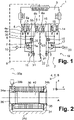
- Fig. 1
- ein elektropneumatisches Schaltschema eines zweikanaligen Achsmodulators für ein Bremssystem eines Fahrzeugs;
- Fig. 2
- einen Schnitt durch ein Vorsteuerventil der elektropneumatischen Vorsteuereinheit ohne Anker und Kern,
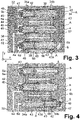
- Fig. 3
bis 5 und Fig. 7 - stellen technische Erläuterungen an einem einkanaligen Stellsystem dar, das technischen Hintergrund darstellt und erfindungsgemäß nicht direkt mit erfasst wird.
Fig. 6 zeigt eine zweikanalige Ausbildung, die Gegenstand der Erfndung ist; somit zeigen: - Fig. 3
- einen schematisierten Schnitt durch eine horizontale Ebene der Steuereinheit gemäß einer einkanaligen Ausbildung;
- Fig. 4eine der Fig. 3
- entsprechende Darstellung bei geänderter Ventilanordnung;
- Fig. 5
- eine perspektivische Ansicht der elektropneumatischen Vorsteuereinheit gemäß
Fig. 3 ; - Fig. 6
- eine erfindungsgemäße zweikanalige Ausbildung in einer der
Fig. 5 entsprechenden Ansicht bei Anschluss von zwei Vorsteuereinheiten für zwei Bremskanäle, zur Ausbildung eines Achsmodulators (ohne ECU); und - Fig. 7
- die Teilschritte a) bis d) der Montage der Vorsteuereinheit, beispielhaft an der Ausbildung der
Fig. 5
- 1
- an electropneumatic circuit diagram of a two-channel axle modulator for a brake system of a vehicle;
- 2
- a section through a pilot valve of the electropneumatic pilot unit without armature and core,
- Figures 3 to 5 and Figure 7
- represent technical explanations of a single-channel control system, which represents the technical background and is not directly recorded according to the invention.
6 shows a two-channel design, which is the subject of the invention; thus show: - 3
- a schematic section through a horizontal plane of the control unit according to a single-channel design;
- Fig. 4 one of Fig. 3
- Corresponding representation with a modified valve arrangement;
- figure 5
- a perspective view of the electropneumatic pilot unit according to FIG
3 ; - 6
- an inventive two-channel training in one of
figure 5 corresponding view with connection of two pilot control units for two brake channels, to form an axle modulator (without ECU); and - 7
- the sub-steps a) to d) the assembly of the pilot control unit, exemplified by the training
figure 5
Bei ausgeschalteter oder ausgefallener elektronischer Steuereinheit 3 ermöglicht der Achsmodulator 1 einen analogen Bremsbetrieb, bei dem ein analoger Steuer-Bremsdruck p4, der von dem Fahrer durch ein Bremspedal und ein an das Bremspedal angeschlossenes Bremsventil über eine pneumatische Bremsdruck- Steuerleitung 22 zu einem Eingangsanschluss 23 eingegeben wird, sowohl an eine erste Bremsleitung 11 des ersten Bremskreises 9 als auch an eine zweite Bremsleitung 21 des zweiten Bremskreises 19 auszugeben.When the
Nachfolgend wird der Achsmodulator 1 weiter mit Bezug zum ersten Bremskreis 9 beschrieben. In dem ersten Bremskreis 9 ist ein erstes Redundanzventil 6 als elektropneumatisches 2/2- Vorsteuer-Sperrventil, und entsprechend im zweiten Bremskreis 19 ein vorzugsweise identisch ausgebildetes zweites Redundanzventil 16 vorgesehen. Die beiden Redundanzventile 6, 16 sind im nichtbestromten Grundzustand offen; somit ist der pneumatische Eingangsanschluss 6a des ersten Redundanzventils 6 mit dessen Ausgangsanschluss 6b verbunden, der wiederum über eine pneumatische Steuerleitung 30 an den Steuereingang (Eingangsanschluss) 7a bzw. Vorsteuer-Raum 50 des Relaisventil 7 angeschlossen ist. Das Relaisventil 7 empfängt somit den über den Ausgangsanschluss 6b des Redundanzventils 6 ausgegebenen analogen Brems-Steuerdruck p1, um von seinem ersten Vorratsdruck-Anschluss 10 von einem Druckluftvorrat aufgenommenen Vorratsdruck (Systemdruck) p0 in Abhängigkeit des Brems-Steuerdrucks p1 auf die erste Bremsleitung 11 auszugeben. Hierdurch wird eine pneumatische Rückfallebene bei Ausfall der elektronischen Steuereinheit 3 gewährleistet.The
Bei eingeschalteter fehlerfreier elektronischer Steuereinheit 3 werden die Redundanzventile 6 und 16 beim Bremsen bestromt, d. h. somit gesperrt, und die weiteren elektromagnetischen Vorsteuer-Ventile 4, 5 sowie entsprechend 14 und 15 angesteuert. Hierbei wird entsprechend in dem ersten Bremskreis 9 Systemdruck p0 von dem Vorratsanschluss 10 über das getaktete Einlassventil 4 auf die pneumatische Steuerleitung 30 und somit zu dem Steuereingang 7a des Relaisventils 7 gegeben. Die elektronische Steuereinheit 3 misst hierbei über den Drucksensor 8 den ausgegebenen Steuerdruck p2 und taktet das Einlassventil 4 derartig, dass der gewünschte Druckwert in der pneumatischen Steuerleitung 30 eingestellt wird, der dann von dem Relaisventil 7 volumenmäßig verstärkt an die erste Bremsleitung 11 ausgegeben wird. Entsprechend dient das erste Auslassventil 5 dazu, die pneumatische Steuerleitung 30 zu entlüften, indem das erste Auslassventil 5 die pneumatische Steuereinrichtung 30 an einen Entlüftungsanschluss 31 legt. Das Auslassventil 5 kann hierbei getaktet oder nicht getaktet ausgesteuert werden. In
Somit dienen im ersten Bremskreis 9 die drei elektromagnetischen Vorsteuer-Ventile 4, 5, 6 zur pneumatischen Vorsteuerung bzw. Ansteuerung des pneumatischen Steuereingangs 7a des Relaisventils 7 und sind mit ihren Ausgangsanschlüssen 4b, 5b, 6b über die pneumatische Steuerleitung 30 an den pneumatischen Steuereingang 7a des Relaisventils 7 angeschlossen.Thus, in the first brake circuit 9, the three
Die ersten Vorsteuer-Ventile 4, 5, 6 zusammen mit angeschlossenen Leitungen bilden eine erste elektropneumatische Vorsteuereinheit 32 (Ansteuermodul), an die die elektronische Steuereinheit 3 elektrisch angeschlossen wird und weiterhin der Steuereingang 7a des Relaisventils 7 pneumatisch angeschlossen wird. Weiterhin weist die Vorsteuereinheit 32 die oben genannten pneumatischen Anschlüsse auf, d.h. den Vorratsdruck-Anschluss 10 für den Vorratsdruck p0, den Eingangsanschluss 23 für die pneumatische Bremsdruck- Steuerleitung 22 und einen Entlüftungsanschluss 31.The
Die elektropneumatische Vorsteuereinheit 32 wird als Einheit auf das Relaisventil 7 aufgesetzt, wobei bei der Hardware-Realisierung die Anschlüsse 4b, 5a und 6b zu einer Unterseite 32b der Vorsteuereinheit 32 hin ragen und direkt an den Steuereingang 7a des Relaisventils 7 angeschlossen werden, insbesondere sogar in einen Vorsteuerraum bzw. Kolbenraum des Relaisventils 7, so die pneumatische Steuerleitung 30 nicht separat zu realisieren ist und bei der Hardware-Ausbildung faktisch entfallen kann bzw. als Teil des Vorsteuerraums des Relaisventils 7 anzusehen ist.The electropneumatic
Die Hardware-Ausbildung der drei ersten Vorsteuer-Ventile 4, 5, 6 ist insbesondere aus
In den 34a und 34b sind zwischen den Vorsteuer-Ventilen 4, 5, 6 jeweils Unterbrechungen 44 oder Löcher ausgebildet, um eine magnetischen Querfluss zwischen den Vorsteuer-Ventilen 4, 5, 6 zu unterdrücken.In FIGS. 34a and 34b, interruptions 44 or holes are formed between the
Die Ausbildung der Vorsteuer-Ventile 4, 5, 6 ist im Wesentlichen gleich und kann somit gemeinsam beschrieben werden. Sie weisen jeweils eine Ventilachse A auf, deren Axialrichtung nachfolgend als x-Richtung beschrieben wird; die Vorsteuer-Ventile 4, 5, 6 liegen in einer Querrichtung y nebeneinander und werden in der vertikalen z-Richtung mit der Steuereinheit 3 und dem Relaisventil 7 verbunden. Somit liegt eine Symmetrieachse B des Relaisventils 7 in z-Richtung und somit senkrecht zu den Ventilachsen AThe design of the
Die Spule 38 wird über ihre elektrischen Kontakte 39a, 39b (Steckkontakte) angesteuert und umgibt den Ventil-Innenraum 40 mit der Ventilachse A. In dem Ventilinnenraum 40 sind in Axialrichtung x verstellbare Anker 42 sowie ein sich in Axialrichtung x anschließender Kern 43 (Ventilrohr) aufgenommen, die jeweils wiederum aus weichmagnetischem Material, z. B. ferritischem Stahl, gefertigt sind. Somit wird bei Bestromung der Spule 38 ein Magnetfluss erzeugt, der in Richtung der Ventilachse A zunächst durch den Anker 42 und den Kern 43 zu den Schenkeln 34a und 34b des Jochbügels 34, und weiter über den mittleren Bügelbereich 34c des Jochbügels 34 geschlossen wird.The
Das Einlassventil 4 und das Auslassventil 5 sind selbstsperrende 2/2-Magnetventile (Solenoid-Ventile), wohingegen das Redundanzventil 6 ein selbstleitendes (im Grundzustand offenes) 2/2-Sperrventil ist. Dementsprechend ist gemäß
In
In
Gemäß der Darstellung der
Bei Bestromung der Spule 38 des Redundanzventils 6 wird der Anker 42 gegen die Wirkung seiner Ankerfeder 47 in Axialrichtung x verstellt und gelangt gegen den Ventilsitz 45, so dass der pneumatische Durchgang zwischen den Schlitzen 48 und der Durchgangsbohrung 43a des Kerns 43 hierdurch verschlossen wird. Somit sperrt das Redundanzventil 6.When the
Das Einlassventil 4 ist gemäß der gezeigten Ausbildung ebenfalls mit einer Durchgangsbohrung 43a ausgebildet, die jedoch grundsätzlich nicht erforderlich ist, da es als selbstsperrendes 2/2-Sperrventil mit pneumatischen Anschlüssen von einer Seite her ausgebildet ist. Sein Eingangsanschluss 4a liegt somit an dem Versorgungsanschluss 10 mit Vorratsdruck p0 an. Hierbei kann gemäß der gezeigten Ausbildung der Anker 42 an seinem Anschlag 49 den Ventilsitz 45 zu seinem Ausgangsanschluss 4b bilden. Der Ausgangsanschluss 4b kann direkt in vertikaler Richtung bzw. -Z-Richtung, d. h. in
Das Auslassventil 5 ist wiederum als selbstsperrendes 2/2-Sperrventil entsprechend dem Einlassventil 4 ausgebildet, wobei sein Eingangsanschluss 5a wiederum entsprechend den Anschlüssen 6b und 4b direkt vertikal zu dem Vorsteuerraum 50 des Relaisventils 7 führt. Sein Ausgangsanschluss 5b liegt außerhalb des Außenumfangs 52 des Ventilkolbens 51 und kann somit ebenfalls vertikal nach unten weggeführt werden zu einer Ausgangsleitung zur Entlüftung 31. Im gezeigten Grundzustand sperren somit die beiden Vorsteuer-Ventile 4, 5, indem ihr Anker 42 jeweils am Anschlag 49 anliegt und hierdurch einen geschlossenen Ventilsitz 45 bildet. Die Anker 42 der beiden Vorsteuer-Ventile 4, 5 können ohne Ankerschlitze 48 ausgebildet sein, auch kann der Kern 43 ohne Bohrung 43a ausgebildet sein. Die in
Grundsätzlich lassen sich somit in dem Jochbügel 34 elektromagnetische 2/2-Sperrventile mit beliebiger Funktion, sowohl selbstsperrend als auch selbstleitend, anordnen; weiterhin können auch andere Solenoid-Ventile, z. B. 3/2-Ventile, aufgenommen werden.In principle, electromagnetic 2/2-way check valves with any function, both self-locking and self-conducting, can thus be arranged in the
Der Anker 42 kann an beiden axialen Enden oder einem axialen Ende mit einer Dichtung 55, z. B. Gummi, ausgebildet sein, je nachdem, ob z. B. der Anschlag nur am jeweiligen Ventilsitz 45, oder auch der andere Anschlag zu dämpfen ist.The
In
Somit wird ein Modulsystem ermöglicht, das sehr kostengünstig ausbildbar ist, indem ein gemeinsamer Jochbügel 34 aus einem Halbzeug passend gekürzt und eine beliebige Anzahl mehrerer elektromagnetischer Ventile bzw. Vorsteuer-Ventile 4, 5, 6 in y-Richtung nebeneinander aufgenommen wird.This enables a modular system that can be formed very inexpensively by suitably shortening a
Gemäß
Erfindungsgemäß ist gemäß
Bei einer derartigen Ausbildung ist eine komplette Vormontage und Prüfung dieser Vorsteuereinheit bzw. der elektromagnetischen Vorsteuereinheit 32 möglich, d. h. sowohl pneumatisch als auch elektrisch. Dieses Modul kann nachfolgend direkt auf die Relaisventile 7, 17 aufmontiert werden.With such a design, a complete pre-assembly and testing of this pilot unit or the
Auch die in
Die so ausgebildete elektropneumatische Vorsteuereinheit 32 wird dann nachfolgend in vertikaler Richtung, d. h. gemäß den Figuren in -Z-Richtung, vorzugsweise mit dazwischenliegender Relaisventil-Dichtung 56, auf die Relaisventile 7, 17 aufgesetzt. Somit ist eine schnelle Aussteuerung, mit einem geringen zu verstellenden Luftvolumen, weiterhin auch ein geringes zu entlüftendes Luftvolumen, erforderlich. Die in
Somit ist auch ein geringer Energieverbrauch erforderlich, da geringe Luftvolumina zur Ansteuerung zu verstellen und zu entlüften sind, sowie schnelle Betätigung der Ventile 4, 5 und 6 und somit ein geringer elektrischer Strombedarf.This means that low energy consumption is also required, since small air volumes have to be adjusted and vented for control, as well as fast ones Actuation of
Weiterhin können entsprechend auch weitere Drucksensoren, insbesondere zur Messung der Vorratsdrücke p0 und/oder der ausgesteuerten Drucke integriert werden, die auf der Leiterplatte der elektronischen Steuereinrichtung 3 platziert werden.Furthermore, other pressure sensors, in particular for measuring the reservoir pressures p0 and/or the output pressures, can also be integrated accordingly, which are placed on the printed circuit board of the
Die Relaisventil-Dichtung 56 kann als Formdichtung, d. h. Dichtungslayer, zur kompletten Abdichtung sämtlicher Kanäle eingesetzt werden. Gegenüber einer Ausbildung einzelner O-Ringe wird hierdurch die Montage einfacher und kostengünstiger.The relay valve seal 56 may be a molded seal, i. H. Sealing layer, can be used to completely seal all ducts. Compared to a design of individual O-rings, this makes assembly simpler and more cost-effective.
Nachfolgend wird in Teilschritt b) die aus und den pneumatischen Vorsteuer-Ventilen 4, 5, 6 mit ihrem gemeinsamen Jochbügel 34 gebildete Montageeinheit von oben mit einer Montagekraft F auf das Luftführungselement 60 gesetzt. Die Schnapphaken 60a und 60b sind mit Einlaufschrägen 63 ausgebildet, an denen die Ventile 4, 5, 6 entlang gleiten, z. B. mit ihrem gemeinsamen Jochbügel 34. Hierbei biegen sich die Schnapphaken 60a und 60b elastisch nach außen auf, bis in Teilschritt c) die Schnapphaken 60a und 60b in den Freiraum zwischen die Schenkel 34a, 34b des Jochbügels 34 gelangen, so dass die Schnapphaken 60a und 60b bereits aufgrund der elastischen Wirkung ihrer Stege etwas zurückschnappen.Subsequently, in step b), the assembly unit formed by the
Weiterhin sind bei dieser der Darstellung dienenden Ausbildung die Schnapphaken 60a und 60b über elastische Verstellbereiche 64 an dem Gusskörper des Luftführungselementes 60 angebunden, wobei die Verstellbereiche 64 z. B. als Parallelogramm-Steg-Ausbildungen 64 oder andere Parallel- Führungseinrichtung ausgebildet sein können. Hierbei biegen sich die Verstellbereiche 64 gemäß dem Teilschritt c) elastisch derartig durch, dass die Schnapphaken 60a und 60b nach innen zu den Vorsteuerventilen 4, 5, 6 verstellt werden. Somit liegen die Schnapphaken 60a und 60b an dem Schenkel 34a des Jochbügels 34 an.Furthermore, the snap hooks 60a and 60b on
Beim nachfolgenden Nachlassen der vertikal nach unten wirkenden Montagekraft F wird der Jochbügel 34 mit einer Restkraft gegen die Schnapphaken 60a und 60b gedrückt. Diese Restkraft bzw. die mechanische Verspannung hält die so gebildete Vorsteuereinheit 32 während der nachfolgenden Montage zusammen, die über Schraubenlöcher 66 und die auch in
- 11
- Zweikanaliger elektropneumatischer AchsmodulatorTwo-channel electropneumatic axle modulator
- 22
- Bremssystembraking system
- 33
- elektronische Steuereinheit (ECU)electronic control unit (ECU)
- 4, 5, 6; 14, 15, 164, 5, 6; 14, 15, 16
- elektropneumatische Vorsteuer-Ventileelectropneumatic pilot valves
- 44
- erstes Einlassventil, getaktetes 2/2-Sperrventilfirst intake valve, clocked 2/2 check valve
- 4a4a
-
Eingangsanschluss des Einlassventils 4Inlet
valve inlet port 4 - 4b4b
-
Ausgangsanschluss des Einlassventils 4Inlet
valve outlet port 4 - 55
- Auslassventil, 2/2-SperrventilOutlet valve, 2/2 check valve
- 5a5a
-
Eingangsanschluss des Auslassventils 5, zum Relaisventil 7
Outlet valve 5 inlet connection, to relayvalve 7 - 5b5b
-
Ausgangsanschluss des Auslassventils 5, zur Entlüftung 31Outlet port of
exhaust valve 5, to vent 31 - 4c4c
-
elektrischer Steuereingang des Einlassventils 4electrical control input of the
intake valve 4 - 5c5c
-
elektrischer Steuereingang des Auslassventils 5electrical control input of the
exhaust valve 5 - 66
- Redundanzventil, 2/2-SperrventilRedundancy valve, 2/2 shut-off valve
- 6a6a
-
Eingangsanschluss des ersten Redundanzventils 6Inlet connection of the
first redundancy valve 6 - 6b6b
-
Ausgangsanschluss des ersten Redundanzventils 6Output connection of the
first redundancy valve 6 - 6c6c
-
elektrischer Steuereingang des ersten Redundanz-ventils 6electrical control input of the
first redundancy valve 6 - 77
- erstes Relaisventilfirst relay valve
- 7a7a
-
Eingangsanschluss des ersten Relaisventils 7Input port of the
first relay valve 7 - 88th
- erster Drucksensorfirst pressure sensor
- 99
- erster Bremskreis (Bremskanal)first brake circuit (brake channel)
- 1010
- erster Vorratsdruck-Anschlussfirst reservoir pressure connection
- 1111
- erste Bremsleitung (zu den Radbremsen)first brake line (to the wheel brakes)
- 1414
- zweites Einlassventil, getaktetes 2/2-Sperrventilsecond intake valve, clocked 2/2 check valve
- 1515
- zweites Auslassventilsecond exhaust valve
- 1616
- zweites Redundanzventilsecond redundancy valve
- 1717
- zweites Relaisventilsecond relay valve
- 1818
- zweiter Drucksensorsecond pressure sensor
- 1919
- zweiter Bremskreis, Bremskanalsecond brake circuit, brake channel
- 2020
- zweiter Vorratsspeicher-Anschlusssecond storage port
- 2121
- zweite Bremsleitung (zu der Radbremse)second brake line (to the wheel brake)
- 2222
- analoge pneumatische Bremsdruck-Steuerleitung vom Bremsventil und Bremspedalanalogue pneumatic brake pressure control line from brake valve and brake pedal
- p0p0
- Vorratsdruck, Systemdruckreservoir pressure, system pressure
- p2p2
- Steuerdruck EDSEDS control pressure
- p1p1
- Brems-Steuerdruck analog (von pneumatischer Brems-druck-Steuerleitung 22)Analog brake control pressure (from pneumatic brake pressure control line 22)
- 3030
-
pneumatische Steuerleitung zwischen dem Relaisventil 7 und den Vorsteuer-Ventilen 4, 5, 6Pneumatic control line between the
relay valve 7 and thepilot valves - 3232
- elektropneumatische Vorsteuereinheit, Ansteuermodulelectro-pneumatic pilot control unit, control module
- 32a32a
-
Oberseite der Vorsteuereinheit 32Top of
pilot control unit 32 - 32b32b
-
Unterseite der Vorsteuereinheit 32Underside of the
pilot control unit 32 - 3333
- Rückkopplungsleitungfeedback line
- 3434
- Jochbügelyoke strap
- 34a34a
-
erster Schenkel des Jochbügels 34first leg of the
yoke 34 - 34b34b
-
zweiter Schenkel des Jochbügels 34second leg of the
yoke 34 - 34c34c
-
mittlerer Bügelbereich des Jochbügels 34middle bracket area of the
yoke bracket 34 - 35, 3635, 36
- Jochbuchsenyoke bushings
- 3838
- SpuleKitchen sink
- 39a, b39a, b
-
Kontakte der Spule 40 VentilinnenraumContacts of
coil 40 valve interior - 4242
- Ankeranchor
- 4343
- Kern, Ventilrohrcore, valve tube
- 43a43a
-
Durchgangsbohrung im Kern 43Through hole in the
core 43 - 4444
-
Unterbrechungen oder Löcher in den Schenkeln 34a, bDiscontinuities or holes in the
legs 34a,b - 4545
- Ventilsitzvalve seat
- 4747
- Ankerfederanchor spring
- 4848
-
Schlitze im Anker 42Slots in
anchor 42 - 4949
- Anschlagattack
- 5050
-
Vorsteuer-Raum des Relaisventils 7, entspricht dem Eingangsanschluss 7a des Relaisventils 7Pilot chamber of the
relay valve 7, corresponds to theinput port 7a of therelay valve 7 - 5151
-
Steuerkolben oder Membran des Relaisventils 7Relay valve spool or
diaphragm 7 - 5252
- Außenumfang des Steuerkolbens 51Outer circumference of the control piston 51
- 5454
-
Ausnehmung in den Schenkeln 34a, 34bRecess in the
legs - 5555
-
Dichtung am Anker 42Gasket on
anchor 42 - 5656
- Relaisventil-DichtungRelay valve seal
- 6060
- Luftführungselement, insbesondere Kunststoff-SpritzgussAir guiding element, in particular plastic injection molding
- 60a, 60b, 60c, 60d60a, 60b, 60c, 60d
- Schnapphaken, EinrasthakenSnap hook, snap hook
- 6262
- Schraubenscrews
- 6363
- Einlaufschrägen der Schnapphaken 60a und 60bInlet slopes of the snap hooks 60a and 60b
- 6464
-
elastische Verstellbereiche, z. B. Parallelogramm-Steg-Ausbildungen des Luftführungselementes 60elastic adjustment areas, e.g. B. Parallelogram web formations of the
air guiding element 60 - 6666
- Schraubenlöcherscrew holes
- AA
- Ventilachsevalve axis
- BB
-
Symmetrieachse des Relaisventils 7Axis of symmetry of the
relay valve 7 - Ff
- Montagekraftassembly force
- xx
- Axialrichtung der Ventileaxial direction of the valves
- yy
- Querrichtungtransverse direction
- ze.g
- vertikale Richtung, Richtung der Symmetrieachse Bvertical direction, direction of the axis of symmetry B
Claims (13)
- An actuator system (1) that is configured as a two-channel electropneumatic axle modulator (1) for a braking system (2) of a commercial vehicle, wherein the actuator system (1) has:two fluid-actuated consumers (7) anda pilot unit (32) for controlling the fluid-actuated consumer (7), wherein the pilot unit (32) has at least two electromagnetic pilot-valves (4, 5, 6) per consumer (7), each having:- a coil (38) for producing a magnetic flux along a valve axis (A),- an armature (42) which can be displaced in an axial direction (x) of the valve axis (A),- a valve seat (45) that can be closed and released by the armature (42),- a fluid inlet connection (4a, 5a, 6a) for a fluid and a fluid outlet connection (4b, 5b, 6b) for the fluid,wherein in each case at least two of the pilot valves (4, 5, 6) per consumer (7) lie adjacent to one another with parallel valve axes (A) in a transverse direction (y) perpendicular to their axial direction (x),wherein the at least four pilot valves are aligned in axial direction (x), andthe pilot valves (4, 5, 6) each have a connection (4b, 5a, 6b) jutting towards a common underside (32b) for connection to a pilot chamber (50) of the consumer (7) controlled by the pilot valves (4, 5, 6),wherein the pilot unit (32) is placed on a pilot chamber (50) of the consumer (7) forming the fluid inlet connection (7a) in a perpendicular direction (z) vertical to the axial direction (x) of the electromagnetic pilot valves (4, 5, 6, 14, 15, 16).
- The actuator system (1) according to claim 1, characterized in that it has a common analog pneumatic brake pressure control line (22).
- The actuator system (1) according to claim 1 or 2, characterized in that the pilot valves (4, 5, 6) have a common yoke bracket (34) for closing the magnetic flux outside of their valve axes (A), wherein the common yoke bracket (34) has two legs (34a, 34b) extending in a perpendicular lateral direction (y) to the axial direction (x), and wherein the pilot valves (4, 5, 6) lying next to each other are each placed between the two legs (34a, 34b).
- The actuator system (1) according to claim 3, characterized in that material weakening points, e.g., interruptions (44) or holes are respectively formed in the legs (34a, 34b) between two adjacent pilot valves (4, 5, 6) for the reduction of a magnetic flux flowing in transverse direction between different pilot valves.
- The actuator system (1) according to any of the foregoing claims, characterized in that contact pins (39a, 39b) of the pilot valves (4, 5, 6) each protrude in a direction (z) vertical to the axial direction (x), for plug-in contact with a control unit (3) placed thereupon.
- The actuator system (1) according to any of the foregoing claims, characterized in that a common fluid guidance element (60) is connected to the pilot valves (4, 5, 6) in the axial direction (x), in particular for forming further connections (4a, 6a, 5b) of the pilot valves (4, 5, 6) .
- The actuator system (1) according to claim 6, characterized in that the fluid guidance element (60) is) fastened positively and/or with latching means (60a, 60b) to the valves for the formation of a one-piece pilot unit (32).
- The actuator system (1) according to claim 7, characterized in that the fluid guidance element (60) is configured with elastic adjustment regions (64) and elastically adjustable snap hooks (60a, 60b) serving as latching means, which have inlet surfaces (34) for automatic adjustment to the valves (4, 5, 6), e.g., the common yoke bracket (34) of the valves, in the installation, wherein the elastic adjustment regions (64) are configured to form a biasing force pressing the valves (4, 5, 6) over the snap hooks (60a, 60b) against the fluid guidance element (60).
- The actuator system (1) according to any of claims 6 to 8, characterized in that the pilot unit (32) is formed with two channels for controlling a dual-channel axle modulator (1), wherein a plurality of valves (4, 5, 6; 14, 15, 16) are connected with a common yoke bracket (34) to the common, middle air guidance element (60) in the axial direction (x) to both sides respectively for each brake circuit (9, 13).
- The actuator system (1) any of the foregoing claims, characterized in that it has least one relay valve (7, 17) as a fluid-actuated consumer.
- The actuator system (1) claim 10, characterized in that it has two relay valves (7, 17) the axes of symmetry (B) of which are perpendicular to the valve axes (A).
- The actuator system according to any of the foregoing claims, characterized in that an electronic control unit (3) is placed on the pilot unit (32) in vertical direction.
- A method for producing an actuator system (1) according to any of the foregoing claims, having at least the following steps:providing at least one/the yoke bracket (34), positioning next to one another the coils (38) respectively aligned in an axial direction (X) and insertion of the armature (42), a spring (47) and a core (43) into each coil (38) to form the plurality of pilot valves (4, 5, 6), wherein the coils (38) are positioned next to one another in a transverse direction (y) perpendicular to the axial direction (x),connecting a/the common fluid guidance element (60) to the plurality of pilot valves (4, 5, 6) in the axial direction (x) while locking and/or latching,placement of the pilot unit (32) in the vertical direction (Z) on the at least one fluid-actuated consumer (7) and fastening,wherein in the case of the step of connecting the common fluid guidance element (60) to the plurality of pilot valves (4, 5, 6) in turn- the fluid guidance element (60) is placed on an installation device (70) which permits an elastic adjustment of the fluid guidance element (60) (Step a)),- the valves (4, 5, 6) with their common yoke bracket (34) are placed on the fluid guide element (60) (Step b)),- the valves (4, 5, 6) are pressed with an installation force (F) on the fluid guidance element (60), as a result of which at least one/the adjustment region (64) of the fluid guidance element (60) is elastically adjusted and the latching means (60a, 60b) of the fluid guidance element (60) engage the valves (4, 5, 6) or are adjusted to said valves (Step c)),- after removal of the installation force (F) at least the adjustment region (64) forms an elastic restoring force, which presses the valves (4, 5, 6) against the latching means (60a, 60b) and holds the pilot unit (32) together (Step d)), for subsequent installation on the consumer (7).
Applications Claiming Priority (2)
| Application Number | Priority Date | Filing Date | Title |
|---|---|---|---|
| DE102016009944.5A DE102016009944A1 (en) | 2016-08-16 | 2016-08-16 | Pilot control unit, positioning system and method for its production |
| PCT/EP2017/000715 WO2018033231A2 (en) | 2016-08-16 | 2017-06-20 | Pilot unit, actuator system and method for producing said system |
Publications (2)
| Publication Number | Publication Date |
|---|---|
| EP3500462A2 EP3500462A2 (en) | 2019-06-26 |
| EP3500462B1 true EP3500462B1 (en) | 2022-04-27 |
Family
ID=59093517
Family Applications (1)
| Application Number | Title | Priority Date | Filing Date |
|---|---|---|---|
| EP17731808.6A Active EP3500462B1 (en) | 2016-08-16 | 2017-06-20 | Pilot unit, actuator system and method for producing said system |
Country Status (8)
| Country | Link |
|---|---|
| US (1) | US10933856B2 (en) |
| EP (1) | EP3500462B1 (en) |
| JP (1) | JP2019525082A (en) |
| KR (1) | KR20190038481A (en) |
| CN (1) | CN109641578B (en) |
| BR (1) | BR112019003072A2 (en) |
| DE (1) | DE102016009944A1 (en) |
| WO (1) | WO2018033231A2 (en) |
Families Citing this family (4)
| Publication number | Priority date | Publication date | Assignee | Title |
|---|---|---|---|---|
| DE102018108091A1 (en) * | 2018-04-05 | 2019-10-10 | Wabco Gmbh | Electro-pneumatic brake control module for commercial vehicles with redundant pressure connection |
| EP3792535A1 (en) * | 2019-09-12 | 2021-03-17 | A. Raymond et Cie | Flow control valve and system for cleaning a vehicle surface |
| EP3798072B1 (en) | 2019-09-26 | 2021-10-13 | Haldex Brake Products Aktiebolag | Brake system for a commercial vehicle |
| CN114043972A (en) * | 2021-11-30 | 2022-02-15 | 广州瑞立科密汽车电子股份有限公司 | Control system and control method for pedal-like brake-by-wire of commercial vehicle |
Family Cites Families (16)
| Publication number | Priority date | Publication date | Assignee | Title |
|---|---|---|---|---|
| DE2424492A1 (en) * | 1971-11-17 | 1974-12-05 | Wagner Electric Corp | TAX OR CONTROL VALVE FOR VEHICLE BRAKING SYSTEMS WITH AN ANTI-BLOCKING PROTECTION EFFECT |
| DE4013875A1 (en) * | 1990-04-30 | 1991-10-31 | Bosch Gmbh Robert | CONNECTING A SOLENOID VALVE TO A HOUSING BLOCK |
| JPH06341568A (en) * | 1993-06-03 | 1994-12-13 | Toyota Motor Corp | Solenoid valve device |
| WO1995002531A1 (en) * | 1993-07-12 | 1995-01-26 | Alliedsignal Inc. | Antilock modulator valve with variable control orifice |
| DE10003205A1 (en) * | 1999-05-14 | 2000-11-30 | Continental Teves Ag & Co Ohg | Electromagnet |
| DE10062625A1 (en) * | 2000-02-26 | 2001-10-11 | Wabco Gmbh & Co Ohg | Brake pressure modulator for electronic brake systems |
| EP1132274B1 (en) | 2000-02-26 | 2004-04-07 | WABCO GmbH & CO. OHG | Brake Pressure Modulator for electronic braking system |
| DE10009116A1 (en) * | 2000-02-26 | 2001-08-30 | Wabco Gmbh & Co Ohg | Valve device for the pilot control unit of a brake pressure modulator |
| DE10133440C2 (en) * | 2001-07-10 | 2003-06-18 | Knorr Bremse Systeme | Brake system with electro-pneumatic modulator |
| JP2004347077A (en) | 2003-05-26 | 2004-12-09 | Hitachi Unisia Automotive Ltd | Solenoid valve unit |
| US7367636B2 (en) * | 2005-02-16 | 2008-05-06 | Bendix Commercial Vehicle Systems, Llc | Solenoid armature with integrated spherical soft seal |
| DE102005023837A1 (en) * | 2005-05-24 | 2006-12-14 | Continental Teves Ag & Co. Ohg | Electronic control unit with cooling by valve block |
| DE102006044764A1 (en) * | 2006-09-20 | 2008-04-03 | Wabco Gmbh | Valve control unit, in particular pilot control unit for a pressure modulator of a commercial vehicle |
| DE102007052697A1 (en) * | 2007-11-06 | 2009-05-07 | Wabco Gmbh | Solenoid valve unit for an electropneumatic control, in particular for a pressure modulator of a commercial vehicle |
| DE102013203594A1 (en) * | 2012-03-06 | 2013-09-12 | Continental Teves Ag & Co. Ohg | Method for operating a brake system for motor vehicles and brake system |
| DE102014011422A1 (en) * | 2014-07-31 | 2016-02-04 | Wabco Gmbh | Brake pressure modulator of an electronic braking system of a commercial vehicle |
-
2016
- 2016-08-16 DE DE102016009944.5A patent/DE102016009944A1/en not_active Withdrawn
-
2017
- 2017-06-20 KR KR1020187036640A patent/KR20190038481A/en not_active Application Discontinuation
- 2017-06-20 CN CN201780042823.2A patent/CN109641578B/en active Active
- 2017-06-20 BR BR112019003072A patent/BR112019003072A2/en not_active IP Right Cessation
- 2017-06-20 US US16/326,033 patent/US10933856B2/en active Active
- 2017-06-20 JP JP2018567670A patent/JP2019525082A/en not_active Withdrawn
- 2017-06-20 EP EP17731808.6A patent/EP3500462B1/en active Active
- 2017-06-20 WO PCT/EP2017/000715 patent/WO2018033231A2/en unknown
Also Published As
| Publication number | Publication date |
|---|---|
| DE102016009944A1 (en) | 2018-02-22 |
| US20190176792A1 (en) | 2019-06-13 |
| EP3500462A2 (en) | 2019-06-26 |
| US10933856B2 (en) | 2021-03-02 |
| CN109641578A (en) | 2019-04-16 |
| CN109641578B (en) | 2022-02-15 |
| WO2018033231A2 (en) | 2018-02-22 |
| BR112019003072A2 (en) | 2019-05-21 |
| WO2018033231A3 (en) | 2018-06-28 |
| KR20190038481A (en) | 2019-04-08 |
| JP2019525082A (en) | 2019-09-05 |
Similar Documents
| Publication | Publication Date | Title |
|---|---|---|
| EP3500462B1 (en) | Pilot unit, actuator system and method for producing said system | |
| EP1128106B1 (en) | Valve device for a pilot unit of a brake pressure modulator | |
| EP1127764B1 (en) | Construction of a brake pressure modulator for a trailer with electronic braking system | |
| DE102007052697A1 (en) | Solenoid valve unit for an electropneumatic control, in particular for a pressure modulator of a commercial vehicle | |
| EP2066540B1 (en) | Two-stage solenoid valve for an electropneumatic valve control unit | |
| EP1888389B1 (en) | Parking brake mechanism of a vehicle comprising an electro-pneumatic emergency release mechanism | |
| DE102006044764A1 (en) | Valve control unit, in particular pilot control unit for a pressure modulator of a commercial vehicle | |
| WO2006007970A1 (en) | Brake pressure modulator pilot unit | |
| WO2007118674A2 (en) | On-off valve | |
| DE10245815B4 (en) | A compressed air control device for an electronic air suspension system for a vehicle | |
| EP1714846B1 (en) | Valve assembly for the supply of a pressurized air for a vehicle | |
| DE102016109865A1 (en) | Electromagnetic valve device and system | |
| DE19701940A1 (en) | Control valves for hydraulic brake system of motor vehicle | |
| DE102014006511A1 (en) | valve assembly | |
| EP1938009B1 (en) | Fuel valve for supplying fuel to an auxiliary heating device in a motor vehicle | |
| EP0926033A2 (en) | Arrangement with a valve device | |
| DE102019131851A1 (en) | Valve and valve terminal | |
| EP1319566B1 (en) | Solenoid and pressure sensor unit | |
| DE10146497A1 (en) | Electromagnetic control valve has coil to which current is applied to generate electromagnetic field, seal for closing opening into inner chamber screwed into hollow armature | |
| EP3234374B1 (en) | Compressed air device with sealings providing variable flow connections | |
| DE102016219658C5 (en) | Valve device for a vehicle and seat system for a vehicle | |
| EP1319565B1 (en) | Solenoid and pressure sensor unit | |
| DE102018009853A1 (en) | Hydraulic actuating device for actuating actuators in a motor vehicle transmission | |
| DE102020202577B4 (en) | Valve module, valve assembly and method | |
| DE102004044770B3 (en) | Electro pneumatic pressure regulating valve, has solenoid valve arranged within housing of pressure regulating valve, where fluid connection of primary pressure line is conducted by common housing unit |
Legal Events
| Date | Code | Title | Description |
|---|---|---|---|
| STAA | Information on the status of an ep patent application or granted ep patent |
Free format text: STATUS: UNKNOWN |
|
| STAA | Information on the status of an ep patent application or granted ep patent |
Free format text: STATUS: THE INTERNATIONAL PUBLICATION HAS BEEN MADE |
|
| PUAI | Public reference made under article 153(3) epc to a published international application that has entered the european phase |
Free format text: ORIGINAL CODE: 0009012 |
|
| STAA | Information on the status of an ep patent application or granted ep patent |
Free format text: STATUS: REQUEST FOR EXAMINATION WAS MADE |
|
| 17P | Request for examination filed |
Effective date: 20190318 |
|
| AK | Designated contracting states |
Kind code of ref document: A2 Designated state(s): AL AT BE BG CH CY CZ DE DK EE ES FI FR GB GR HR HU IE IS IT LI LT LU LV MC MK MT NL NO PL PT RO RS SE SI SK SM TR |
|
| AX | Request for extension of the european patent |
Extension state: BA ME |
|
| DAV | Request for validation of the european patent (deleted) | ||
| DAX | Request for extension of the european patent (deleted) | ||
| STAA | Information on the status of an ep patent application or granted ep patent |
Free format text: STATUS: EXAMINATION IS IN PROGRESS |
|
| 17Q | First examination report despatched |
Effective date: 20200113 |
|
| STAA | Information on the status of an ep patent application or granted ep patent |
Free format text: STATUS: EXAMINATION IS IN PROGRESS |
|
| RAP3 | Party data changed (applicant data changed or rights of an application transferred) |
Owner name: ZF CV SYSTEMS EUROPE BV |
|
| STAA | Information on the status of an ep patent application or granted ep patent |
Free format text: STATUS: EXAMINATION IS IN PROGRESS |
|
| GRAP | Despatch of communication of intention to grant a patent |
Free format text: ORIGINAL CODE: EPIDOSNIGR1 |
|
| STAA | Information on the status of an ep patent application or granted ep patent |
Free format text: STATUS: GRANT OF PATENT IS INTENDED |
|
| INTG | Intention to grant announced |
Effective date: 20220118 |
|
| GRAS | Grant fee paid |
Free format text: ORIGINAL CODE: EPIDOSNIGR3 |
|
| GRAA | (expected) grant |
Free format text: ORIGINAL CODE: 0009210 |
|
| STAA | Information on the status of an ep patent application or granted ep patent |
Free format text: STATUS: THE PATENT HAS BEEN GRANTED |
|
| AK | Designated contracting states |
Kind code of ref document: B1 Designated state(s): AL AT BE BG CH CY CZ DE DK EE ES FI FR GB GR HR HU IE IS IT LI LT LU LV MC MK MT NL NO PL PT RO RS SE SI SK SM TR |
|
| REG | Reference to a national code |
Ref country code: GB Ref legal event code: FG4D Free format text: NOT ENGLISH |
|
| REG | Reference to a national code |
Ref country code: CH Ref legal event code: EP |
|
| REG | Reference to a national code |
Ref country code: AT Ref legal event code: REF Ref document number: 1486735 Country of ref document: AT Kind code of ref document: T Effective date: 20220515 |
|
| REG | Reference to a national code |
Ref country code: DE Ref legal event code: R096 Ref document number: 502017013072 Country of ref document: DE |
|
| REG | Reference to a national code |
Ref country code: IE Ref legal event code: FG4D Free format text: LANGUAGE OF EP DOCUMENT: GERMAN |
|
| REG | Reference to a national code |
Ref country code: LT Ref legal event code: MG9D |
|
| REG | Reference to a national code |
Ref country code: NL Ref legal event code: MP Effective date: 20220427 |
|
| PG25 | Lapsed in a contracting state [announced via postgrant information from national office to epo] |
Ref country code: NL Free format text: LAPSE BECAUSE OF FAILURE TO SUBMIT A TRANSLATION OF THE DESCRIPTION OR TO PAY THE FEE WITHIN THE PRESCRIBED TIME-LIMIT Effective date: 20220427 |
|
| PG25 | Lapsed in a contracting state [announced via postgrant information from national office to epo] |
Ref country code: SE Free format text: LAPSE BECAUSE OF FAILURE TO SUBMIT A TRANSLATION OF THE DESCRIPTION OR TO PAY THE FEE WITHIN THE PRESCRIBED TIME-LIMIT Effective date: 20220427 Ref country code: PT Free format text: LAPSE BECAUSE OF FAILURE TO SUBMIT A TRANSLATION OF THE DESCRIPTION OR TO PAY THE FEE WITHIN THE PRESCRIBED TIME-LIMIT Effective date: 20220829 Ref country code: NO Free format text: LAPSE BECAUSE OF FAILURE TO SUBMIT A TRANSLATION OF THE DESCRIPTION OR TO PAY THE FEE WITHIN THE PRESCRIBED TIME-LIMIT Effective date: 20220727 Ref country code: LT Free format text: LAPSE BECAUSE OF FAILURE TO SUBMIT A TRANSLATION OF THE DESCRIPTION OR TO PAY THE FEE WITHIN THE PRESCRIBED TIME-LIMIT Effective date: 20220427 Ref country code: HR Free format text: LAPSE BECAUSE OF FAILURE TO SUBMIT A TRANSLATION OF THE DESCRIPTION OR TO PAY THE FEE WITHIN THE PRESCRIBED TIME-LIMIT Effective date: 20220427 Ref country code: GR Free format text: LAPSE BECAUSE OF FAILURE TO SUBMIT A TRANSLATION OF THE DESCRIPTION OR TO PAY THE FEE WITHIN THE PRESCRIBED TIME-LIMIT Effective date: 20220728 Ref country code: FI Free format text: LAPSE BECAUSE OF FAILURE TO SUBMIT A TRANSLATION OF THE DESCRIPTION OR TO PAY THE FEE WITHIN THE PRESCRIBED TIME-LIMIT Effective date: 20220427 Ref country code: ES Free format text: LAPSE BECAUSE OF FAILURE TO SUBMIT A TRANSLATION OF THE DESCRIPTION OR TO PAY THE FEE WITHIN THE PRESCRIBED TIME-LIMIT Effective date: 20220427 Ref country code: BG Free format text: LAPSE BECAUSE OF FAILURE TO SUBMIT A TRANSLATION OF THE DESCRIPTION OR TO PAY THE FEE WITHIN THE PRESCRIBED TIME-LIMIT Effective date: 20220727 |
|
| PG25 | Lapsed in a contracting state [announced via postgrant information from national office to epo] |
Ref country code: RS Free format text: LAPSE BECAUSE OF FAILURE TO SUBMIT A TRANSLATION OF THE DESCRIPTION OR TO PAY THE FEE WITHIN THE PRESCRIBED TIME-LIMIT Effective date: 20220427 Ref country code: PL Free format text: LAPSE BECAUSE OF FAILURE TO SUBMIT A TRANSLATION OF THE DESCRIPTION OR TO PAY THE FEE WITHIN THE PRESCRIBED TIME-LIMIT Effective date: 20220427 Ref country code: LV Free format text: LAPSE BECAUSE OF FAILURE TO SUBMIT A TRANSLATION OF THE DESCRIPTION OR TO PAY THE FEE WITHIN THE PRESCRIBED TIME-LIMIT Effective date: 20220427 Ref country code: IS Free format text: LAPSE BECAUSE OF FAILURE TO SUBMIT A TRANSLATION OF THE DESCRIPTION OR TO PAY THE FEE WITHIN THE PRESCRIBED TIME-LIMIT Effective date: 20220827 |
|
| REG | Reference to a national code |
Ref country code: DE Ref legal event code: R097 Ref document number: 502017013072 Country of ref document: DE |
|
| PG25 | Lapsed in a contracting state [announced via postgrant information from national office to epo] |
Ref country code: SM Free format text: LAPSE BECAUSE OF FAILURE TO SUBMIT A TRANSLATION OF THE DESCRIPTION OR TO PAY THE FEE WITHIN THE PRESCRIBED TIME-LIMIT Effective date: 20220427 Ref country code: SK Free format text: LAPSE BECAUSE OF FAILURE TO SUBMIT A TRANSLATION OF THE DESCRIPTION OR TO PAY THE FEE WITHIN THE PRESCRIBED TIME-LIMIT Effective date: 20220427 Ref country code: RO Free format text: LAPSE BECAUSE OF FAILURE TO SUBMIT A TRANSLATION OF THE DESCRIPTION OR TO PAY THE FEE WITHIN THE PRESCRIBED TIME-LIMIT Effective date: 20220427 Ref country code: MC Free format text: LAPSE BECAUSE OF FAILURE TO SUBMIT A TRANSLATION OF THE DESCRIPTION OR TO PAY THE FEE WITHIN THE PRESCRIBED TIME-LIMIT Effective date: 20220427 Ref country code: EE Free format text: LAPSE BECAUSE OF FAILURE TO SUBMIT A TRANSLATION OF THE DESCRIPTION OR TO PAY THE FEE WITHIN THE PRESCRIBED TIME-LIMIT Effective date: 20220427 Ref country code: DK Free format text: LAPSE BECAUSE OF FAILURE TO SUBMIT A TRANSLATION OF THE DESCRIPTION OR TO PAY THE FEE WITHIN THE PRESCRIBED TIME-LIMIT Effective date: 20220427 Ref country code: CZ Free format text: LAPSE BECAUSE OF FAILURE TO SUBMIT A TRANSLATION OF THE DESCRIPTION OR TO PAY THE FEE WITHIN THE PRESCRIBED TIME-LIMIT Effective date: 20220427 |
|
| REG | Reference to a national code |
Ref country code: CH Ref legal event code: PL |
|
| REG | Reference to a national code |
Ref country code: BE Ref legal event code: MM Effective date: 20220630 |
|
| PLBE | No opposition filed within time limit |
Free format text: ORIGINAL CODE: 0009261 |
|
| STAA | Information on the status of an ep patent application or granted ep patent |
Free format text: STATUS: NO OPPOSITION FILED WITHIN TIME LIMIT |
|
| PG25 | Lapsed in a contracting state [announced via postgrant information from national office to epo] |
Ref country code: AL Free format text: LAPSE BECAUSE OF FAILURE TO SUBMIT A TRANSLATION OF THE DESCRIPTION OR TO PAY THE FEE WITHIN THE PRESCRIBED TIME-LIMIT Effective date: 20220427 |
|
| 26N | No opposition filed |
Effective date: 20230130 |
|
| PG25 | Lapsed in a contracting state [announced via postgrant information from national office to epo] |
Ref country code: LU Free format text: LAPSE BECAUSE OF NON-PAYMENT OF DUE FEES Effective date: 20220620 Ref country code: LI Free format text: LAPSE BECAUSE OF NON-PAYMENT OF DUE FEES Effective date: 20220630 Ref country code: IE Free format text: LAPSE BECAUSE OF NON-PAYMENT OF DUE FEES Effective date: 20220620 Ref country code: CH Free format text: LAPSE BECAUSE OF NON-PAYMENT OF DUE FEES Effective date: 20220630 |
|
| PG25 | Lapsed in a contracting state [announced via postgrant information from national office to epo] |
Ref country code: SI Free format text: LAPSE BECAUSE OF FAILURE TO SUBMIT A TRANSLATION OF THE DESCRIPTION OR TO PAY THE FEE WITHIN THE PRESCRIBED TIME-LIMIT Effective date: 20220427 Ref country code: BE Free format text: LAPSE BECAUSE OF NON-PAYMENT OF DUE FEES Effective date: 20220630 |
|
| P01 | Opt-out of the competence of the unified patent court (upc) registered |
Effective date: 20230528 |
|
| PGFP | Annual fee paid to national office [announced via postgrant information from national office to epo] |
Ref country code: FR Payment date: 20230621 Year of fee payment: 7 Ref country code: DE Payment date: 20230630 Year of fee payment: 7 |
|
| REG | Reference to a national code |
Ref country code: AT Ref legal event code: MM01 Ref document number: 1486735 Country of ref document: AT Kind code of ref document: T Effective date: 20220620 |
|
| PG25 | Lapsed in a contracting state [announced via postgrant information from national office to epo] |
Ref country code: AT Free format text: LAPSE BECAUSE OF NON-PAYMENT OF DUE FEES Effective date: 20220620 |
|
| PGFP | Annual fee paid to national office [announced via postgrant information from national office to epo] |
Ref country code: GB Payment date: 20230622 Year of fee payment: 7 |
|
| PG25 | Lapsed in a contracting state [announced via postgrant information from national office to epo] |
Ref country code: IT Free format text: LAPSE BECAUSE OF FAILURE TO SUBMIT A TRANSLATION OF THE DESCRIPTION OR TO PAY THE FEE WITHIN THE PRESCRIBED TIME-LIMIT Effective date: 20220427 |
|
| PG25 | Lapsed in a contracting state [announced via postgrant information from national office to epo] |
Ref country code: HU Free format text: LAPSE BECAUSE OF FAILURE TO SUBMIT A TRANSLATION OF THE DESCRIPTION OR TO PAY THE FEE WITHIN THE PRESCRIBED TIME-LIMIT; INVALID AB INITIO Effective date: 20170620 |
|
| PG25 | Lapsed in a contracting state [announced via postgrant information from national office to epo] |
Ref country code: MK Free format text: LAPSE BECAUSE OF FAILURE TO SUBMIT A TRANSLATION OF THE DESCRIPTION OR TO PAY THE FEE WITHIN THE PRESCRIBED TIME-LIMIT Effective date: 20220427 Ref country code: CY Free format text: LAPSE BECAUSE OF FAILURE TO SUBMIT A TRANSLATION OF THE DESCRIPTION OR TO PAY THE FEE WITHIN THE PRESCRIBED TIME-LIMIT Effective date: 20220427 |