EP3500382B1 - Tool body for a shell end mill and cutting tool - Google Patents
Tool body for a shell end mill and cutting tool Download PDFInfo
- Publication number
- EP3500382B1 EP3500382B1 EP17841779.6A EP17841779A EP3500382B1 EP 3500382 B1 EP3500382 B1 EP 3500382B1 EP 17841779 A EP17841779 A EP 17841779A EP 3500382 B1 EP3500382 B1 EP 3500382B1
- Authority
- EP
- European Patent Office
- Prior art keywords
- tool body
- cutting insert
- cutting
- indexable cutting
- base surface
- Prior art date
- Legal status (The legal status is an assumption and is not a legal conclusion. Google has not performed a legal analysis and makes no representation as to the accuracy of the status listed.)
- Active
Links
Images


Classifications
-
- B—PERFORMING OPERATIONS; TRANSPORTING
- B23—MACHINE TOOLS; METAL-WORKING NOT OTHERWISE PROVIDED FOR
- B23C—MILLING
- B23C5/00—Milling-cutters
- B23C5/16—Milling-cutters characterised by physical features other than shape
- B23C5/20—Milling-cutters characterised by physical features other than shape with removable cutter bits or teeth or cutting inserts
- B23C5/22—Securing arrangements for bits or teeth or cutting inserts
- B23C5/2204—Securing arrangements for bits or teeth or cutting inserts with cutting inserts clamped against the walls of the recess in the cutter body by a clamping member acting upon the wall of a hole in the insert
- B23C5/2208—Securing arrangements for bits or teeth or cutting inserts with cutting inserts clamped against the walls of the recess in the cutter body by a clamping member acting upon the wall of a hole in the insert for plate-like cutting inserts
-
- B—PERFORMING OPERATIONS; TRANSPORTING
- B23—MACHINE TOOLS; METAL-WORKING NOT OTHERWISE PROVIDED FOR
- B23C—MILLING
- B23C5/00—Milling-cutters
- B23C5/16—Milling-cutters characterised by physical features other than shape
- B23C5/20—Milling-cutters characterised by physical features other than shape with removable cutter bits or teeth or cutting inserts
-
- B—PERFORMING OPERATIONS; TRANSPORTING
- B23—MACHINE TOOLS; METAL-WORKING NOT OTHERWISE PROVIDED FOR
- B23C—MILLING
- B23C5/00—Milling-cutters
- B23C5/28—Features relating to lubricating or cooling
-
- B—PERFORMING OPERATIONS; TRANSPORTING
- B23—MACHINE TOOLS; METAL-WORKING NOT OTHERWISE PROVIDED FOR
- B23C—MILLING
- B23C2210/00—Details of milling cutters
- B23C2210/16—Fixation of inserts or cutting bits in the tool
- B23C2210/163—Indexing
-
- B—PERFORMING OPERATIONS; TRANSPORTING
- B23—MACHINE TOOLS; METAL-WORKING NOT OTHERWISE PROVIDED FOR
- B23C—MILLING
- B23C2210/00—Details of milling cutters
- B23C2210/16—Fixation of inserts or cutting bits in the tool
- B23C2210/168—Seats for cutting inserts, supports for replacable cutting bits
-
- B—PERFORMING OPERATIONS; TRANSPORTING
- B23—MACHINE TOOLS; METAL-WORKING NOT OTHERWISE PROVIDED FOR
- B23C—MILLING
- B23C2250/00—Compensating adverse effects during milling
- B23C2250/12—Cooling and lubrication
-
- B—PERFORMING OPERATIONS; TRANSPORTING
- B23—MACHINE TOOLS; METAL-WORKING NOT OTHERWISE PROVIDED FOR
- B23C—MILLING
- B23C5/00—Milling-cutters
- B23C5/006—Details of the milling cutter body
Definitions
- the invention relates to a tool body according to the preamble of claim 1 for a shell end mill having at least one spiral-shaped chip discharge flute arranged on a periphery of the tool body for discharging chips, and at least two receptacles for cutting inserts arranged at the at least one chip discharge flute, wherein each receptacle comprises a base surface with a hole for receiving a cutting insert mounting screw, and at least one first contact surface, which adjoins the base surface and is orthogonal to the base surface.
- the invention furthermore relates to a shell end mill with a tool body of the type mentioned above.
- Shell end mills which as a rule have a circular cylindrical basic shape, are used for machining tasks, in which a cutting process is to take place both on the end surface and on the shell surface of the shell end mill.
- the shell end mill comprises cutting edges, which are constituted for example by cutting inserts, both on the end surface and on its shell surface.
- a shell end mill of the type mentioned above, or more precisely its tool body comprises several chip discharge flutes. On each chip discharge flute, a multitude of cutting inserts mounted on receptacles is arranged. Such a shell end mill thus comprises a multitude of cutting inserts and just as many associated receptacles.
- the designs of the respective tool body and of the cutting tool as a whole are therefore complex and accordingly expensive.
- the task of the invention is therefore to further improve cutting tools of the type mentioned above.
- the cost effectiveness of such tools in the machining of tools is to be improved.
- the task is solved by a tool body according to claim 1.
- the tool body is of the type mentioned above, in which the transition between the base surface and the first contact surface is a groove.
- the base surface and the first contact surface thus do not form a physical edge. Rather, the groove at the transition between the two surfaces constitutes a recess, i.e. material has been removed in comparison to surfaces abutting against each other directly.
- the cross-section of the groove may be any shape, for example rectangular, circular or oval.
- double-sided cutting inserts which are characterized by comprising cutting edges on both sides, can be arranged in the receptacles.
- a quadrangular, double-sided cutting insert thus has eight cutting edges, a triangular cutting insert has six.
- the groove is arranged such that a cutting edge, which lies on the side of the double-sided cutting insert that is not used for the cutting at the time, can be received therein.
- the cutting edge is arranged on the inside of the groove and does not contact the end faces of the groove and thus not contact the tool body. A precise positioning of the double-sided cutting insert using the base surface and the first contact surface is thus still possible.
- At least one coolant outlet opening for cooling a cutting process is arranged on the end surface of the tool body. These coolant outlet openings also serve to increase the cutting speed and/or the material removal rate. A multitude of coolant outlet openings may also be arranged on the end surface.
- the groove lies at least partially behind the base surface and behind the first contact surface.
- the groove is thus set back with respect to the base surface, when viewed orthogonally to the base surface.
- the groove is also set back, when viewed orthogonally to the first contact surface.
- the cutting edge also does not come into contact with the delimiting walls of the groove or the tool body during the mounting and aligning of the cutting insert and is therefore protected.
- the base surfaces enclose different angles with a longitudinal axis of the tool body.
- This angle which is called an alignment angle or tool-sided machining angle, significantly affects the cutting result.
- all base surfaces that are provided on the end surface of the tool body for receiving cutting inserts for cutting may have a different alignment angle than the other base surfaces.
- the alignment angle may however also be defined individually for each base surface. The individual alignment angles as are calculated in the course of an optimization method, for which the finite element method can be used. Thus, the real entrance and exit angles of the indexable cutting inserts mounted on the respective recordings can be considered. In this way, a high quality cutting result can be achieved in a cost-effective manner.
- the receptacle comprises a second contact surface that adjoins the first contact surface and the base surface.
- a cutting insert mounted in the receptacle is thus secured on the base surface using a cutting insert mounting screw and positioned by abutting against the two contact surfaces.
- the interaction of the cutting insert mounting screw and the respective mounting hole in the cutting insert can be designed such that the cutting insert is pulled against the two contact surfaces during tightening of the cutting insert mounting screw.
- one contact surface may be arranged such that it supports a cutting insert mounted in the receptacle substantially in an axial direction of the tool body and the other contact surface is arranged to provide radial support.
- the transition between the first contact surface and the second contact surface is a groove.
- cutting inserts with any corner radius can thus be arranged and abutted against the contact surfaces.
- the groove at the transition between the two contact surfaces may also extend at least in regions behind each of these surfaces. Because any contaminations, e.g. in the form of chips, can be accommodated in the groove when the cutting inserts are abutted against the contact surfaces, a precise positioning of the cutting inserts is always possible.
- each receptacle is associated with a coolant outlet opening arranged in the tool body for cooling a cutting insert received in the receptacle.
- a coolant outlet opening arranged in the tool body for cooling a cutting insert received in the receptacle.
- the coolant outlet openings are designed such that they are directed toward a specific target region, e.g. toward the cutting edge, of a cutting insert mounted in the receptacle.
- each receptacle may also be associated with two or three coolant outlet openings.
- a variant provides that two coolant outlet openings are allocated to first two rows in each case as seen from the end face of the tool body from.
- the coolant outlet openings may be designed as twin openings, i.e. they are fed by a common coolant channel.
- the coolant may support the chip dissipation.
- the tool body comprises between two and ten, preferably between five and seven, chip discharge flutes with receptacles for cutting inserts and the chip discharge flutes are in particular distributed asymmetrically on the periphery of the tool body.
- chip discharge flutes with receptacles for cutting inserts and the chip discharge flutes are in particular distributed asymmetrically on the periphery of the tool body. In this way, a tool body results, which ensures a cost-effective performance of cutting tasks.
- the tool body may be produced as one piece. In this case, a high mechanical stability of the tool body results.
- the tool body can be designed, for example, using the finite element method. In addition, such a tool body satisfies close tolerances, since mounting steps are dispensed with and no tolerance chain occurs. Precise and cost-effective cutting is thus possible.
- receptacles are arranged along the chip discharge flute. On each chip discharge flute, the same number of cutting inserts can thus be mounted. In this way, cost-effective cutting is ensured.
- An alternative embodiment provides that on the base surface a projection for centering of an indexable cutting insert is arranged, wherein preferably the bore extends through the projection therethrough.
- a indexable cutting insert mounted in the receptacle may be oriented along the base surface, e.g., centered.
- a positive connection between the projection and the assembled indexable cutting insert results parallel to the base.
- the bore extends through the projection therethrough, the bore may be designed deeper in comparison with a receptacle without projection. Then, e.g., a long thread may be arranged in the bore. The installation of the indexable cutting insert is facilitated and the fastening of the indexable cutting insert is improved.
- the task is also solved by a shell end mill, with a tool body according to the present invention, wherein a double-sided cutting insert is mounted in each receptacle.
- a double-sided cutting insert is mounted in each receptacle.
- twice the number of cutting edges is thus available.
- the tool life of the cutting tool is thus substantially doubled, which corresponds to a significant increase in cost effectiveness.
- the cutting inserts may have any shape, e.g. polyangular or round.
- the cutting inserts that are arranged on the end surface of a chip discharge flute can be arranged for end-surface machining.
- the other cutting inserts are as a rule arranged for peripheral machining.
- a cutting edge on the mounting side is arranged in the groove at the transition between the base surface and the first contact surface.
- the cutting inserts may have a negative rake angle.
- a positive rake angle is also possible, depending on the cutting task.
- the cutting insert comprises two base surfaces on the cutting insert side, which are set back toward the inside of the cutting insert compared to associated cutting edges.
- the cutting edges protrude the base surface in a direction orthogonal to the base surface on the cutting insert side.
- a double-sided cutting insert comprises two base surfaces on the cutting insert side, one on each side. In the mounted condition, one of the base surfaces on the cutting insert side respectively abuts against the base surface on the tool body side. It is thus ensured that the cutting insert is precisely positioned in any position, i.e. in any rotary position or orientation.
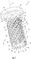
- a shell end mill 10 comprises a tool body 12, which has substantially a circular cylindrical shape with a longitudinal axis of tool body 14.
- the tool body 12 comprises a clamping-sided end 16 with which it can be clamped in a machine tool, not shown, and an opposite, machining-sided end 18. On the machining-sided end 18, an end face [front surface] 20 is arranged.
- the shell end mill 10 is designed for machining on its end face 20 and at its circumference 22.
- the circumference 22 may also be referred to as a lateral surface.
- the tool body 12 is designed integrally.
- chip guiding grooves 24 are arranged. These extend spirally around the circumference 22 of the tool body 12 and serve the chip dissipation.
- the tool body 12 comprises five, six or seven chip guiding grooves 24.
- the tool body may also comprise more or fewer chip guiding grooves 24.
- the chip guiding grooves 24 are unevenly distributed around the circumference 22 of the tool body 12. This means that the angular spacings between adjacent chip guiding grooves 24 are different in terms of distance.
- indexable cutting inserts 26 are arranged.
- the indexable cutting inserts 26 are each set in a receptacle 28 and designed bilaterally. Such indexable cutting insert 26 is shown in Figure 6 . However, there may be other, indexable cutting inserts, not shown in the demonstrated shell end mill 10.
- the receptacles 28 each comprise a base surface 30.
- a respective indexable cutting insert-sided base surface 32 is located adjacent to this base surface 30. Then, the indexable cutting insert 26 is attached to the receptacle 28 with an indexable cutting insert fixing screw 34, which engages in a hole 35 of the base surface 30.
- each indexable cutting insert 26 comprises two indexable cutting insert-sided base surfaces 32.
- the indexable cutting insert-sided base surfaces 32 are set back relative to cutting edges 36, which are arranged on the same side.
- the indexable cutting inserts 26 have a negative rake angle in the illustrated embodiment.
- the inclination of the inserts 26 may be adjusted to the tool's longitudinal axis 14 via the inclination of the base surface 30 to the tool body axis 14.
- the angle between the base surface 30 and the longitudinal axis of the tool body 14 may be individually selected depending upon the cutting application for each base surface.
- each corresponding base surfaces 30 are equal, which are arranged in adjacent chip guiding grooves 24. This means, e.g., that all third base surfaces 30 and therefore all third indexable cutting inserts 26 have the same angle along the chip guiding grooves 24 with respect to the tool body longitudinal axis 14. However, the angle of the individual base areas 30 differ within a chip guiding groove 24.
- the receptacle 28 includes a first abutment surface 37 and a second abutment surface 38.
- the indexable cutting insert 26 When assembled, the indexable cutting insert 26 is available with one of its side surface 40 is located adjacent to the abutment surface 37 and the abutment surface 38, respectively.
- Both the first abutment surface 37 and the second abutment surface 38 are adjacent to the base surface 30.
- first abutment surface 37 is substantially perpendicular to the abutment surface 30.
- second abutment surface 38 is substantially perpendicular to the base surface 30.
- first abutment surface 37 and second abutment surface 38 are substantially perpendicular to each other.
- the transition between the base surface 30 and the first abutment surface 37 is designed as a groove 42.
- This groove 42 is designed so that it is located behind the base surface 30, when viewed in a direction perpendicular to the base surface 30 and is located behind the first abutment surface 37, when viewed in a direction perpendicular to the abutment surface 37.
- the groove 42 may have a rectangular cross section.
- the groove 42 has a circular cross section.
- a comparable groove 30 of the base surface not shown is provided at the transition to the second abutment surface 38.
- the transition between the first abutment surface 37 and the second abutment surface 38 is also designed as a groove 44.
- the groove 44 has a circular cross-section, however, it may have any desired cross section as groove 42.
- indexable cutting inserts 26 are mounted in the seats 28, a differentiation must be made between a clamping-sided side of the receptacle 26 and a cutting-sided side of the indexable cutting insert 26.
- the clamping-sided side of the indexable cutting insert 26 is oriented towards the base surface 30.
- the cutting edges 36 on this page are not involved in the machining.
- the cutting-sided side is opposite to the clamping-sided side.
- One of disposed cutting edges 36 takes part in the machining.
- At least one cutting edge 36 is arranged in the groove 42 on the clamping-sided side of the indexable cutting insert 26. This can be seen in Figure 4 and Figure 5 .
- a projection 48 is arranged on the base surface 30.
- the indexable cutting insert 26 may be centered during assembly. For this purpose, it must have a projection 48 associated with the geometry of the projection. Centering is designed "easy" that no double fit may arise between the abutment surfaces 37, 38, the indexable cutting insert 26 and the projection 48.
- the projection 48 has the shape of a circular cylinder and the bore 35 is arranged centrally in the projection 48.
- the indexable cutting insert 26 During assembly of the indexable cutting insert 26, it is first prepositioned on the projection 48 and then arranged to the abutment surfaces 37, 38 in the course of screwing in the indexable cutting insert attachment screw 34.
- indexable cutting inserts 26 are positioned on each chip guiding groove 24.
- indexable cutting inserts 26 are provided with a reference number.
- the number of indexable cutting inserts 26 at each chip guiding groove may be determined, inter alia, depending on the length of the tool body and the size of the indexable cutting inserts 26 to be used.
- the shell end mill 10 may be operated with the use of coolants or refrigerants. Unspecified coolant channels are provided in the tool body 12.
- each receptacle 28 and therefore each indexable cutting insert 26 is associated with a coolant outlet opening 50, which is fed via the cooling channels.
- the receptacle and indexable cutting insert received therein may be cooled during the machining process.
- only selected coolant outlet openings 50 are provided with a reference mark.
- Each two coolant outlet openings 50 may be associated to those receptacles 28, which are located in the first and second row viewed from the end face 20. Then, the coolant flow additionally supports the chip dissipation. This can be seen in Figure 3 . Likewise, the cooling channels fed via coolant outlet openings 52 are arranged on the end face 20 of the tool body 12.
Landscapes
- Engineering & Computer Science (AREA)
- Mechanical Engineering (AREA)
- Milling Processes (AREA)
- Cutting Tools, Boring Holders, And Turrets (AREA)
Description
- The invention relates to a tool body according to the preamble of claim 1 for a shell end mill having at least one spiral-shaped chip discharge flute arranged on a periphery of the tool body for discharging chips, and at least two receptacles for cutting inserts arranged at the at least one chip discharge flute, wherein each receptacle comprises a base surface with a hole for receiving a cutting insert mounting screw, and at least one first contact surface, which adjoins the base surface and is orthogonal to the base surface.
- The invention furthermore relates to a shell end mill with a tool body of the type mentioned above.
- Such tool bodies and cutting tools are known from the prior art, e.g. from
US 2014/0341660 A1 ,US 2016/0031020 A1 andUS 2013/0129429 A1 . Shell end mills, which as a rule have a circular cylindrical basic shape, are used for machining tasks, in which a cutting process is to take place both on the end surface and on the shell surface of the shell end mill. For this purpose, the shell end mill comprises cutting edges, which are constituted for example by cutting inserts, both on the end surface and on its shell surface. - As a rule, a shell end mill of the type mentioned above, or more precisely its tool body, comprises several chip discharge flutes. On each chip discharge flute, a multitude of cutting inserts mounted on receptacles is arranged. Such a shell end mill thus comprises a multitude of cutting inserts and just as many associated receptacles. The designs of the respective tool body and of the cutting tool as a whole are therefore complex and accordingly expensive.
- During the tool life, the price of a cutting tool is included in the machining costs. For this reason, machining a tool using a cutting tool of the type mentioned above, which comprises a tool body of the type mentioned above, is expensive.
- The task of the invention is therefore to further improve cutting tools of the type mentioned above. In particular, the cost effectiveness of such tools in the machining of tools is to be improved.
- The task is solved by a tool body according to claim 1. The tool body is of the type mentioned above, in which the transition between the base surface and the first contact surface is a groove. The base surface and the first contact surface thus do not form a physical edge. Rather, the groove at the transition between the two surfaces constitutes a recess, i.e. material has been removed in comparison to surfaces abutting against each other directly. The cross-section of the groove may be any shape, for example rectangular, circular or oval. By means of the groove, double-sided cutting inserts, which are characterized by comprising cutting edges on both sides, can be arranged in the receptacles. A quadrangular, double-sided cutting insert thus has eight cutting edges, a triangular cutting insert has six. The groove is arranged such that a cutting edge, which lies on the side of the double-sided cutting insert that is not used for the cutting at the time, can be received therein. The cutting edge is arranged on the inside of the groove and does not contact the end faces of the groove and thus not contact the tool body. A precise positioning of the double-sided cutting insert using the base surface and the first contact surface is thus still possible. By using double-sided cutting inserts instead of single-sided cutting inserts, the cost effectiveness of the cutting tool and the tool body in machining is increased.
- Additionally, at least one coolant outlet opening for cooling a cutting process is arranged on the end surface of the tool body. These coolant outlet openings also serve to increase the cutting speed and/or the material removal rate. A multitude of coolant outlet openings may also be arranged on the end surface.
- Preferably, the groove lies at least partially behind the base surface and behind the first contact surface. The groove is thus set back with respect to the base surface, when viewed orthogonally to the base surface. The groove is also set back, when viewed orthogonally to the first contact surface. There is thus enough space for receiving a cutting edge of a double-sided cutting insert. The cutting edge also does not come into contact with the delimiting walls of the groove or the tool body during the mounting and aligning of the cutting insert and is therefore protected.
- In one embodiment, the base surfaces enclose different angles with a longitudinal axis of the tool body. This angle, which is called an alignment angle or tool-sided machining angle, significantly affects the cutting result. In particular, all base surfaces that are provided on the end surface of the tool body for receiving cutting inserts for cutting may have a different alignment angle than the other base surfaces. Depending on the cutting task, the alignment angle may however also be defined individually for each base surface. The individual alignment angles as are calculated in the course of an optimization method, for which the finite element method can be used. Thus, the real entrance and exit angles of the indexable cutting inserts mounted on the respective recordings can be considered. In this way, a high quality cutting result can be achieved in a cost-effective manner.
- One design variant provides that the receptacle comprises a second contact surface that adjoins the first contact surface and the base surface. A cutting insert mounted in the receptacle is thus secured on the base surface using a cutting insert mounting screw and positioned by abutting against the two contact surfaces. The interaction of the cutting insert mounting screw and the respective mounting hole in the cutting insert can be designed such that the cutting insert is pulled against the two contact surfaces during tightening of the cutting insert mounting screw. In this case, one contact surface may be arranged such that it supports a cutting insert mounted in the receptacle substantially in an axial direction of the tool body and the other contact surface is arranged to provide radial support. Thus, a precise and simple positioning of cutting inserts is possible and cutting inserts can be quickly exchanged and turned.
- Advantageously, the transition between the first contact surface and the second contact surface is a groove. In the receptacle, cutting inserts with any corner radius can thus be arranged and abutted against the contact surfaces. Like the groove at the transition of the base surface to the first contact surface, the groove at the transition between the two contact surfaces may also extend at least in regions behind each of these surfaces. Because any contaminations, e.g. in the form of chips, can be accommodated in the groove when the cutting inserts are abutted against the contact surfaces, a precise positioning of the cutting inserts is always possible.
- In one design alternative, each receptacle is associated with a coolant outlet opening arranged in the tool body for cooling a cutting insert received in the receptacle. In this way, higher cutting speeds and/or material removal rates can be achieved with consistently high cutting quality. Also with the cooling, the life span of indexable cutting insert, more specifically the cutting edge increases. The coolant outlet openings are designed such that they are directed toward a specific target region, e.g. toward the cutting edge, of a cutting insert mounted in the receptacle. Alternatively, each receptacle may also be associated with two or three coolant outlet openings.
- A variant provides that two coolant outlet openings are allocated to first two rows in each case as seen from the end face of the tool body from. The coolant outlet openings may be designed as twin openings, i.e. they are fed by a common coolant channel. The coolant may support the chip dissipation.
- Preferably, the tool body comprises between two and ten, preferably between five and seven, chip discharge flutes with receptacles for cutting inserts and the chip discharge flutes are in particular distributed asymmetrically on the periphery of the tool body. In this way, a tool body results, which ensures a cost-effective performance of cutting tasks.
- The tool body may be produced as one piece. In this case, a high mechanical stability of the tool body results. The tool body can be designed, for example, using the finite element method. In addition, such a tool body satisfies close tolerances, since mounting steps are dispensed with and no tolerance chain occurs. Precise and cost-effective cutting is thus possible.
- In a preferred embodiment, between three and thirty, preferably between five and twenty, receptacles are arranged along the chip discharge flute. On each chip discharge flute, the same number of cutting inserts can thus be mounted. In this way, cost-effective cutting is ensured.
- An alternative embodiment provides that on the base surface a projection for centering of an indexable cutting insert is arranged, wherein preferably the bore extends through the projection therethrough. With the help of the projection a indexable cutting insert mounted in the receptacle may be oriented along the base surface, e.g., centered. At the same time, a positive connection between the projection and the assembled indexable cutting insert results parallel to the base. If the bore extends through the projection therethrough, the bore may be designed deeper in comparison with a receptacle without projection. Then, e.g., a long thread may be arranged in the bore. The installation of the indexable cutting insert is facilitated and the fastening of the indexable cutting insert is improved.
- The task is also solved by a shell end mill, with a tool body according to the present invention, wherein a double-sided cutting insert is mounted in each receptacle. Compared to a cutting tool with single-sided cutting inserts, twice the number of cutting edges is thus available. The tool life of the cutting tool is thus substantially doubled, which corresponds to a significant increase in cost effectiveness. The cutting inserts may have any shape, e.g. polyangular or round. The cutting inserts that are arranged on the end surface of a chip discharge flute can be arranged for end-surface machining. The other cutting inserts are as a rule arranged for peripheral machining.
- Advantageously, a cutting edge on the mounting side is arranged in the groove at the transition between the base surface and the first contact surface.
- The cutting inserts may have a negative rake angle. A positive rake angle is also possible, depending on the cutting task.
- In one variant, the cutting insert comprises two base surfaces on the cutting insert side, which are set back toward the inside of the cutting insert compared to associated cutting edges. In other words, the cutting edges protrude the base surface in a direction orthogonal to the base surface on the cutting insert side. A double-sided cutting insert comprises two base surfaces on the cutting insert side, one on each side. In the mounted condition, one of the base surfaces on the cutting insert side respectively abuts against the base surface on the tool body side. It is thus ensured that the cutting insert is precisely positioned in any position, i.e. in any rotary position or orientation.
- The invention will be explained below with reference to various exemplary embodiments that are shown in the accompanying drawings. The figures show:
-
Figure 1 illustrates a cutting tool with a too body according to the present invention in accordance with a first embodiment with seven chip discharge flutes in a perspective view, -
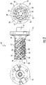
Figure 2 illustrates a cutting tool with a too body according to the present invention in accordance with a second embodiment with five chip discharge flutes in a three-view drawing, -
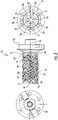
Figure 3 illustrates a cutting tool with a too body according to the present invention in accordance with a third embodiment with six chip discharge flutes in a three-view drawing, -
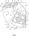
Figure 4 illustrates a detailed view of two cutting inserts of a cutting tool, which are respectively mounted in a receptacle of a tool body according to the present invention, -
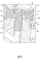
Figure 5 is a sectional view of an indexable cutting insert fastened in a receptacle of an inventive tool body and -
Figure 6 is an indexable cutting insert of an inventive cutting tool in plan view and sectional view. -
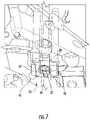
Figure 7 is a detail view of an alternative embodiment of a receptacle for an inventive tool body. - Embodiments described herein can be understood more readily by reference to the following detailed description and examples and their previous and following descriptions. Elements, apparatus and methods described herein, however, are not limited to the specific embodiments presented in the detailed description and examples. It should be recognized that these embodiments are merely illustrative of the present invention. Numerous modifications and adaptations will be readily apparent to those of skill in the art without departing from the scope of the invention.
- A
shell end mill 10 comprises atool body 12, which has substantially a circular cylindrical shape with a longitudinal axis oftool body 14. - The
tool body 12 comprises a clamping-sided end 16 with which it can be clamped in a machine tool, not shown, and an opposite, machining-sided end 18. On the machining-sided end 18, an end face [front surface] 20 is arranged. - The
shell end mill 10 is designed for machining on itsend face 20 and at itscircumference 22. Thecircumference 22 may also be referred to as a lateral surface. - In the illustrated embodiment the
tool body 12 is designed integrally. - In the
tool body 12chip guiding grooves 24 are arranged. These extend spirally around thecircumference 22 of thetool body 12 and serve the chip dissipation. - In the illustrated embodiments, the
tool body 12 comprises five, six or sevenchip guiding grooves 24. Depending on the diameter of the tool body and the size of the used indexable cutting inserts 26, the tool body may also comprise more or fewerchip guiding grooves 24. - With particular reference to
Figure 2 and Figure, thechip guiding grooves 24 are unevenly distributed around thecircumference 22 of thetool body 12. This means that the angular spacings between adjacentchip guiding grooves 24 are different in terms of distance. - At the
chip guiding grooves 24 indexable cutting inserts 26 are arranged. - The indexable cutting inserts 26 are each set in a
receptacle 28 and designed bilaterally. Suchindexable cutting insert 26 is shown inFigure 6 . However, there may be other, indexable cutting inserts, not shown in the demonstratedshell end mill 10. - The
receptacles 28 each comprise abase surface 30. A respective indexable cutting insert-sided base surface 32 is located adjacent to thisbase surface 30. Then, theindexable cutting insert 26 is attached to thereceptacle 28 with an indexable cuttinginsert fixing screw 34, which engages in ahole 35 of thebase surface 30. - Since these are two-sided indexable cutting inserts 26 in the illustrated embodiment, each
indexable cutting insert 26 comprises two indexable cutting insert-sided base surfaces 32. As can be seen particularly inFigure 6 , the indexable cutting insert-sided base surfaces 32 are set back relative to cuttingedges 36, which are arranged on the same side. - The indexable cutting inserts 26 have a negative rake angle in the illustrated embodiment.
- The inclination of the
inserts 26 may be adjusted to the tool'slongitudinal axis 14 via the inclination of thebase surface 30 to thetool body axis 14. The angle between thebase surface 30 and the longitudinal axis of thetool body 14 may be individually selected depending upon the cutting application for each base surface. - In the illustrated embodiment, the angles of each corresponding base surfaces 30 are equal, which are arranged in adjacent
chip guiding grooves 24. This means, e.g., that all third base surfaces 30 and therefore all third indexable cutting inserts 26 have the same angle along thechip guiding grooves 24 with respect to the tool bodylongitudinal axis 14. However, the angle of theindividual base areas 30 differ within achip guiding groove 24. - Further, the
receptacle 28 includes afirst abutment surface 37 and asecond abutment surface 38. - When assembled, the
indexable cutting insert 26 is available with one of itsside surface 40 is located adjacent to theabutment surface 37 and theabutment surface 38, respectively. - Both the
first abutment surface 37 and thesecond abutment surface 38 are adjacent to thebase surface 30. - As seen in
Figure 5 , thefirst abutment surface 37 is substantially perpendicular to theabutment surface 30. Similarly, thesecond abutment surface 38 is substantially perpendicular to thebase surface 30. - Since rectangular indexable cutting inserts 26 are used in the illustrated embodiment, the
first abutment surface 37 andsecond abutment surface 38 are substantially perpendicular to each other. - The transition between the
base surface 30 and thefirst abutment surface 37 is designed as agroove 42. - This
groove 42 is designed so that it is located behind thebase surface 30, when viewed in a direction perpendicular to thebase surface 30 and is located behind thefirst abutment surface 37, when viewed in a direction perpendicular to theabutment surface 37. - As seen in
Figure 4 , thegroove 42 may have a rectangular cross section. - In the
receptacle 28 shown inFigure 5 , thegroove 42 has a circular cross section. - A
comparable groove 30 of the base surface not shown is provided at the transition to thesecond abutment surface 38. - As shown in
Figure 4 , the transition between thefirst abutment surface 37 and thesecond abutment surface 38 is also designed as agroove 44. - In the illustrated embodiment, the
groove 44 has a circular cross-section, however, it may have any desired cross section asgroove 42. - If the indexable cutting inserts 26 are mounted in the
seats 28, a differentiation must be made between a clamping-sided side of thereceptacle 26 and a cutting-sided side of theindexable cutting insert 26. The clamping-sided side of theindexable cutting insert 26 is oriented towards thebase surface 30. The cutting edges 36 on this page are not involved in the machining. The cutting-sided side is opposite to the clamping-sided side. One ofdisposed cutting edges 36 takes part in the machining. - In the assembled state of the
indexable cutting insert 26, at least onecutting edge 36 is arranged in thegroove 42 on the clamping-sided side of theindexable cutting insert 26. This can be seen inFigure 4 andFigure 5 . - In an alternative embodiment of the
receptacle 28, shown inFigure 7 , aprojection 48 is arranged on thebase surface 30. On thisprojection 48 theindexable cutting insert 26 may be centered during assembly. For this purpose, it must have aprojection 48 associated with the geometry of the projection. Centering is designed "easy" that no double fit may arise between the abutment surfaces 37, 38, theindexable cutting insert 26 and theprojection 48. - In the illustrated embodiment, the
projection 48 has the shape of a circular cylinder and thebore 35 is arranged centrally in theprojection 48. - During assembly of the
indexable cutting insert 26, it is first prepositioned on theprojection 48 and then arranged to the abutment surfaces 37, 38 in the course of screwing in the indexable cuttinginsert attachment screw 34. - In the illustrated embodiment, thirteen or seventeen indexable cutting inserts 26 are positioned on each
chip guiding groove 24. For clarity, only individual indexable cutting inserts 26 are provided with a reference number. The number of indexable cutting inserts 26 at each chip guiding groove may be determined, inter alia, depending on the length of the tool body and the size of the indexable cutting inserts 26 to be used. - The
shell end mill 10 may be operated with the use of coolants or refrigerants. Unspecified coolant channels are provided in thetool body 12. - In the illustrated embodiment, each
receptacle 28 and therefore eachindexable cutting insert 26 is associated with a coolant outlet opening 50, which is fed via the cooling channels. Thus, the receptacle and indexable cutting insert received therein may be cooled during the machining process. For clarity, only selectedcoolant outlet openings 50 are provided with a reference mark. - Each two
coolant outlet openings 50 may be associated to thosereceptacles 28, which are located in the first and second row viewed from theend face 20. Then, the coolant flow additionally supports the chip dissipation. This can be seen inFigure 3 . Likewise, the cooling channels fed viacoolant outlet openings 52 are arranged on theend face 20 of thetool body 12. - Various embodiments of the invention have been described in fulfillment of the various objects of the invention. It should be recognized that these embodiments are merely illustrative of the present invention. Numerous modifications and adaptations thereof will be readily apparent to those skilled in the art without departing from the scope of the invention.
Claims (13)
- A tool body for a shell end mill (10), the tool body (12) comprising:at least one spiral-shaped chip guiding groove (24) arranged on a circumference (22) of the tool body (12) for chip dissipation; andat least two receptacles (28) for indexable cutting inserts (26) arranged at the at least one chip-guiding groove (24), wherein each receptacle (28) comprises a base surface (30) comprising a bore (35) for receiving an indexable cutting insert fastening screw (34) and at least one first abutment surface (37) located adjacent to the base surface (30), the first abutment surface (37) being perpendicular to the base surface (30), wherein the transition between the base surface (30) and the first abutment surface (37) is a groove (42), characterized in that at least one coolant outlet opening (52) is arranged for cooling of a machining process on the end face (20) of the tool body (12).
- The tool body according to claim 1, characterized in that the groove (42) is located at least partially behind the base surface (30) and behind the first abutment surface (37).
- The tool body according to one of claims 1 and 2, characterized in that the base surfaces (30) enclose different angles with a tool body longitudinal axis (14).
- The tool body according to one of the preceding claims, characterized in that the receptacle (28) comprises a second abutment surface (38) that is adjacent to the first abutment surface (37) and the base surface (30).
- The tool body according to claim 4, characterized in that the transition between the first abutment surface (27) and the second abutment surface (38 is a groove (44).
- The tool body according to one of the preceding claims, characterized in that each receptacle (28) has a coolant outlet opening (50) for cooling of an indexable cutting insert (26) in the receptacle (28) arranged in the tool body (12).
- The tool body according to one of the preceding claims, characterized in that it comprises between two and ten, preferably between five and seven chip guiding grooves (24) with receptacles for indexable cutting inserts and the chip guiding grooves (24) non-uniformly distributed at the circumference (22) of the tool body (12).
- The tool body according to one of the preceding claims, characterized in that the tool body (12) is prepared integrally.
- The tool body according to one of the preceding claims, characterized in that a projection (48) is arranged on the base surface (30), the projection (48) being arranged for centering an indexable cutting insert (26) on the base surface (30), wherein the bore (35) extends through the projection (48).
- A shell end mill comprising a tool body (12) according to one of the preceding claims, wherein a two-sided indexable cutting insert (26) is attached to each receptacle (28).
- The shell end mill according to claim 10, characterized in that at least one clamping-sided cutting edge (36) in the groove (42) is arranged at the transition between the base surface (30) and the first abutment surface (37).
- The shell end mill according to claim 10 or 11, characterized in that the two-sided indexable cutting insert (26) has a negative rake angle.
- The shell end mill according to one of claims 10 to 12, characterized in that the two-sided indexable cutting insert (26) comprises two indexable cutting insert-sided base surfaces (32) located toward the interior of the indexable cutting insert (26) set back relative to associated cutting edges (36).
Applications Claiming Priority (2)
| Application Number | Priority Date | Filing Date | Title |
|---|---|---|---|
| US15/238,214 US10556278B2 (en) | 2016-08-16 | 2016-08-16 | Tool body for a shell end mill and cutting tool |
| PCT/US2017/029389 WO2018034710A1 (en) | 2016-08-16 | 2017-04-25 | Tool body for a shell end mill and cutting tool |
Publications (3)
| Publication Number | Publication Date |
|---|---|
| EP3500382A1 EP3500382A1 (en) | 2019-06-26 |
| EP3500382A4 EP3500382A4 (en) | 2020-04-01 |
| EP3500382B1 true EP3500382B1 (en) | 2022-08-24 |
Family
ID=61191069
Family Applications (1)
| Application Number | Title | Priority Date | Filing Date |
|---|---|---|---|
| EP17841779.6A Active EP3500382B1 (en) | 2016-08-16 | 2017-04-25 | Tool body for a shell end mill and cutting tool |
Country Status (6)
| Country | Link |
|---|---|
| US (2) | US10556278B2 (en) |
| EP (1) | EP3500382B1 (en) |
| JP (3) | JP2019524467A (en) |
| CA (1) | CA3030627C (en) |
| RU (1) | RU2721761C1 (en) |
| WO (1) | WO2018034710A1 (en) |
Families Citing this family (10)
| Publication number | Priority date | Publication date | Assignee | Title |
|---|---|---|---|---|
| US10556278B2 (en) * | 2016-08-16 | 2020-02-11 | Kennametal Inc. | Tool body for a shell end mill and cutting tool |
| DE102017122054A1 (en) | 2017-09-22 | 2019-03-28 | Kennametal Inc. | Cutting tool and method for producing a cutting tool |
| WO2020054558A1 (en) * | 2018-09-12 | 2020-03-19 | 住友電工ハードメタル株式会社 | Cutting tool |
| JP6892637B2 (en) * | 2019-01-17 | 2021-06-23 | 株式会社タンガロイ | Cutting tool with replaceable cutting edge |
| DE102019127027A1 (en) * | 2019-10-08 | 2021-04-08 | Kennametal Inc. | Cutting tool |
| US11529691B2 (en) | 2019-12-02 | 2022-12-20 | Kennametal Inc. | Rotary cutting tool with hybrid cutting insert design |
| WO2022215114A1 (en) * | 2021-04-05 | 2022-10-13 | 住友電工ハードメタル株式会社 | Cutting tool |
| JP7010407B1 (en) * | 2021-08-30 | 2022-01-26 | 株式会社タンガロイ | Cutting tools |
| JP7057550B1 (en) * | 2021-08-30 | 2022-04-20 | 株式会社タンガロイ | Cutting tools |
| EP4438209B1 (en) * | 2023-03-28 | 2025-10-08 | Seco Tools AB | Double-sided cutting insert and helical milling cutter |
Citations (19)
| Publication number | Priority date | Publication date | Assignee | Title |
|---|---|---|---|---|
| EP0094921A1 (en) | 1982-05-17 | 1983-11-23 | Santrade Ltd. | Cutting insert |
| EP0278389A2 (en) | 1987-02-06 | 1988-08-17 | Ingersoll Maschinen Und Werkzeuge Gesellschaft Mit Beschränkter Haftung | Cutting insert for a milling tool, and a milling tool equipped with a such an insert |
| US4919573A (en) | 1987-09-22 | 1990-04-24 | Mitsubishi Kinzoku Kabushiki Kaisha | Ball end mill |
| JPH02100728U (en) | 1989-01-27 | 1990-08-10 | ||
| JPH02117813U (en) | 1989-03-10 | 1990-09-20 | ||
| GB2240740A (en) | 1990-02-07 | 1991-08-14 | H & B Quickgrind Limited | Toothed rotary cutting tools |
| US5542793A (en) | 1993-08-03 | 1996-08-06 | Walter Ag | Rotary cutting tool with axially precision positioned end cutting inserts |
| DE19609820A1 (en) | 1995-03-15 | 1996-09-19 | Plansee Metallwerk | Boring and milling tool which consists of cylindrical body with cutter bits |
| US6203251B1 (en) | 1998-10-17 | 2001-03-20 | Wilhelm Fette Gmbh | Indexable milling insert |
| EP1129806A1 (en) | 2000-02-11 | 2001-09-05 | Sandvik Aktiebolag | Machining tool |
| EP1322452A1 (en) | 2000-10-04 | 2003-07-02 | Kennametal Inc. | Milling cutter |
| FR2837732A1 (en) | 2002-03-29 | 2003-10-03 | Stellram | STRAINER WITH REMOVABLE CUTTING PLATES FOR VERY HIGH SPEED MACHINING |
| JP2005022063A (en) | 2003-07-03 | 2005-01-27 | Tungaloy Corp | Arbor and rotating tool |
| US7160062B2 (en) | 2004-01-12 | 2007-01-09 | Toan Dat Tran | Milling cutter |
| EP2167264A1 (en) | 2007-06-05 | 2010-03-31 | Sandvik Intellectual Property Ab | A tool for chip removing machining as well as a basic body and an indexable cutting insert therefor |
| JP2011206887A (en) | 2010-03-30 | 2011-10-20 | Mitsubishi Materials Corp | Coolant supply hole structure of cutting tool |
| US20130129429A1 (en) | 2011-11-23 | 2013-05-23 | Kennametal Inc. | Rotary cutting tool with coolant passage disposed in non-circular recess for reducing stress |
| US20140341660A1 (en) | 2012-02-08 | 2014-11-20 | Taegutec, Ltd. | Cutting Insert Having Eight Main Cutting Edges and Eight Wiper Edges and Cutting Tool Including The Same |
| US20160031020A1 (en) | 2014-08-01 | 2016-02-04 | Kennametal Inc. | Rotary cutting tool with regrindable cutting inserts |
Family Cites Families (77)
| Publication number | Priority date | Publication date | Assignee | Title |
|---|---|---|---|---|
| US3018675A (en) | 1959-11-23 | 1962-01-30 | Wesson Corp | Boring bar |
| US4078868A (en) * | 1977-04-06 | 1978-03-14 | The Ingersoll Milling Machine Company | Cutter having inserts clamped with wedges |
| SU763090A1 (en) | 1978-12-13 | 1980-09-15 | Центральный научно-исследовательский институт механической обработки древесины | Circular saw for cutting wooden materials |
| US4341493A (en) * | 1980-04-07 | 1982-07-27 | General Electric Company | Adjustable clamping wedge system for cutting insert of a milling cutter |
| DE3234238A1 (en) | 1982-09-15 | 1984-03-15 | August Beck GmbH & Co, 7472 Winterlingen | DRILLER WITH INSERT |
| SU1201072A1 (en) | 1984-06-12 | 1985-12-30 | Архангельский Ордена Трудового Красного Знамени Лесотехнический Институт Им.В.В.Куйбышева | Method of making saws |
| GB8522424D0 (en) * | 1985-09-10 | 1985-10-16 | Marwin Cutting Tools Ltd | Mounting of tool blades |
| JPH0621619Y2 (en) * | 1986-09-25 | 1994-06-08 | 日立ツール株式会社 | Rotary cutting tool |
| IL85606A (en) * | 1988-03-02 | 1994-02-27 | Amram Dotany | Helical cutting tool |
| JP3525349B2 (en) * | 1994-03-14 | 2004-05-10 | 日本特殊陶業株式会社 | Cutting tool holder |
| US5924826A (en) * | 1994-04-27 | 1999-07-20 | Sandvik Ab | Cutting insert mounted on holder by rib-and-groove coupling |
| DE4430171C2 (en) | 1994-08-25 | 1996-08-14 | Walter Ag | Form-locked insert |
| JP3376727B2 (en) * | 1994-11-11 | 2003-02-10 | 三菱マテリアル株式会社 | Indexable end mill |
| SE505511C2 (en) | 1994-12-15 | 1997-09-08 | Sandvik Ab | Milling body and method of manufacture thereof |
| SE509363C2 (en) * | 1995-09-25 | 1999-01-18 | Sandvik Ab | Fixing device removes cutting plates and cutting plate intended for such device |
| DE19611276C1 (en) * | 1996-03-22 | 1997-03-20 | Walter Ag | Rotary groove-cutting tool |
| US5882150A (en) | 1996-07-18 | 1999-03-16 | Dijet Industrial Co., Ltd. | Indexable end mill |
| IL119841A (en) | 1996-12-16 | 2000-02-29 | Iscar Ltd | Cutting inserts |
| AU7716098A (en) | 1997-06-05 | 1998-12-21 | Gregory S. Antoun | Tool holder with integral coolant passage and replaceable nozzle |
| SE512040C2 (en) | 1998-05-06 | 2000-01-17 | Sandvik Ab | Inserts for stick cutters |
| US6247878B1 (en) | 1999-10-12 | 2001-06-19 | Kennametal Pc Inc. | Device and method for adjusting the position of cutting inserts mounted in a cutting tool |
| SE525496C2 (en) * | 2002-03-21 | 2005-03-01 | Sandvik Ab | Tools for chip separator machining as well as rotary cutter for such tools |
| US6811359B2 (en) | 2002-05-31 | 2004-11-02 | Kennametal Inc. | True helical cutter system |
| EP1375037A1 (en) * | 2002-06-25 | 2004-01-02 | Ngk Spark Plug Co., Ltd | Insert, holder and cutting tool |
| SE525325C2 (en) * | 2003-05-16 | 2005-02-01 | Sandvik Ab | Cutting tools for metalworking and method of manufacturing cutting tools |
| IL159157A (en) | 2003-12-02 | 2008-03-20 | Amir Satran | Rotary slot milling cutter and cutting insert therefor |
| US7004689B2 (en) * | 2004-01-09 | 2006-02-28 | Kennametal Inc. | High-speed milling cutter and insert |
| IL160223A (en) | 2004-02-04 | 2008-11-26 | Carol Smilovici | Double-sided cutting insert and milling cutter |
| SE527543C2 (en) | 2004-08-30 | 2006-04-04 | Sandvik Intellectual Property | Cutting position with grooved support surface |
| US7325471B2 (en) * | 2004-09-07 | 2008-02-05 | Kennametal Inc. | Toolholder and cutting insert for a toolholder assembly |
| SE0402760L (en) * | 2004-11-10 | 2006-05-09 | Sandvik Intellectual Property | Cutting tools for metalworking and method of manufacturing cutting tools |
| US7040844B1 (en) | 2005-03-08 | 2006-05-09 | Mitsubishi Materials Corporation | Throwaway insert and throwaway-type rotary cutting tool |
| US7204662B1 (en) | 2005-11-17 | 2007-04-17 | Kennametal Inc. | Cutting tool with stress splitter |
| SE0600876L (en) * | 2006-04-20 | 2007-10-21 | Sandvik Intellectual Property | Tools and inserts for chip separating machining with primary and secondary meshes with rotationally symmetrical shape |
| US7429150B2 (en) * | 2006-05-31 | 2008-09-30 | Kennametal Inc. | Tool holder with spherical contact points |
| EP2060353B1 (en) * | 2006-09-13 | 2012-12-19 | Mitsubishi Materials Corporation | Roughing insert, and roughing end mill |
| JP4799344B2 (en) | 2006-09-27 | 2011-10-26 | 京セラ株式会社 | ROLLING TOOL HOLDER AND ROLLING TOOL WITH THE SAME |
| SE530631C2 (en) * | 2006-12-12 | 2008-07-22 | Sandvik Intellectual Property | Tools and cutters for chip separating machining |
| US7963729B2 (en) * | 2007-01-18 | 2011-06-21 | Kennametal Inc. | Milling cutter and milling insert with coolant delivery |
| US7625157B2 (en) | 2007-01-18 | 2009-12-01 | Kennametal Inc. | Milling cutter and milling insert with coolant delivery |
| IL182100A (en) | 2007-03-21 | 2010-11-30 | Taegutec India Ltd | Cutting insert for a milling cutter |
| IL182343A0 (en) | 2007-04-01 | 2007-07-24 | Iscar Ltd | Cutting insert and tool for milling and ramping at high feed rates |
| US7566192B2 (en) | 2007-10-19 | 2009-07-28 | Kennametal Inc. | Axial seating pin |
| IL188502A (en) * | 2007-12-30 | 2012-05-31 | Iscar Ltd | Cutting insert and cutting tool therefor |
| JP5060614B2 (en) | 2008-02-27 | 2012-10-31 | 京セラ株式会社 | Cutting insert for drill, drill, and cutting method using the same |
| FR2928284B1 (en) | 2008-03-10 | 2010-06-04 | Safety Production | "CHIP DEFLECTOR CUTTING PLATE" |
| RU2383393C1 (en) | 2008-11-10 | 2010-03-10 | Федеральное государственное образовательное учреждение высшего профессионального образования Красноярский государственный аграрный университет | Electric filter |
| US9623493B2 (en) | 2008-11-19 | 2017-04-18 | Kennametal Inc. | Double-sided ball end mill cutting insert and tool therefor |
| US8454284B2 (en) | 2008-12-01 | 2013-06-04 | Kennametal Inc. | Milling cutter coupling system |
| US8454277B2 (en) * | 2008-12-18 | 2013-06-04 | Kennametal Inc. | Toolholder and toolholder assembly with elongated seating pads |
| US7922427B2 (en) | 2008-12-18 | 2011-04-12 | Kennametal Inc. | Toolholder and toolholder assembly with elongated seating pads |
| EP2397248B1 (en) | 2009-02-13 | 2018-04-04 | Tungaloy Corporation | Cutting tool with cutting inserts |
| US7931425B2 (en) * | 2009-03-18 | 2011-04-26 | Kennametal Inc. | Cutting tool having coolant delivery system for providing cutting fluid in a fan-like pattern |
| JP5310191B2 (en) | 2009-03-30 | 2013-10-09 | 三菱マテリアル株式会社 | Insert detachable cutting tool |
| US8215878B2 (en) * | 2009-04-22 | 2012-07-10 | Creare Incorporated | Indirect cooling of a rotary cutting tool |
| US8858126B2 (en) * | 2009-09-25 | 2014-10-14 | Kennametal Inc. | Cutting tool with error proofing feature |
| US8807884B2 (en) * | 2009-12-18 | 2014-08-19 | Kennametal Inc. | Tool holder for multiple differently-shaped cutting inserts |
| IL204235A (en) * | 2010-03-02 | 2013-04-30 | Iscar Ltd | Adjustable cooling division for extended flute milling cutter |
| SE534832C2 (en) * | 2010-05-10 | 2012-01-17 | Sandvik Intellectual Property | Indexable cutter for milling tools |
| US8561509B2 (en) | 2010-06-15 | 2013-10-22 | Kennametal Inc. | Mechanical-activated ID grooving tool |
| JP5403167B2 (en) | 2010-09-30 | 2014-01-29 | 株式会社タンガロイ | Replaceable cutting tool |
| US8439609B2 (en) * | 2010-10-04 | 2013-05-14 | Michigan Technological University | Micro-jet cooling of cutting tools |
| US8596935B2 (en) | 2010-10-08 | 2013-12-03 | TDY Industries, LLC | Cutting tools and cutting inserts including internal cooling |
| RU2604547C2 (en) | 2010-11-24 | 2016-12-10 | Ноу Скрю Лтд. | Cutting tool with cooling mechanism, as well as cutting insert and tool holder |
| US8657539B2 (en) * | 2011-03-28 | 2014-02-25 | Kennametal Inc. | Round cutting insert with reverse anti-rotation feature |
| US8647026B2 (en) * | 2011-11-23 | 2014-02-11 | Kennametal Inc. | Cutting tool with pocket feature for reducing stress |
| US8821079B2 (en) * | 2012-03-06 | 2014-09-02 | Iscar, Ltd. | Cutting tool and cutting insert therefor |
| JP2013202770A (en) * | 2012-03-29 | 2013-10-07 | Mitsubishi Materials Corp | Blade edge replaceable end mill and end mill main body used for the same |
| US9011049B2 (en) * | 2012-09-25 | 2015-04-21 | Kennametal Inc. | Double-sided cutting inserts with anti-rotation features |
| KR101452073B1 (en) * | 2012-12-24 | 2014-10-16 | 대구텍 유한회사 | Cutting insert and milling cutter having the same |
| US9475131B2 (en) * | 2013-06-13 | 2016-10-25 | Kennametal Inc. | Milling cutter with stress reliefs |
| US10124423B2 (en) * | 2014-07-14 | 2018-11-13 | Tungaloy Corporation | Rotary cutting tool having adjacent cutting inserts with wave-shaped edges and overlapping rotational trajectories coinciding in phase |
| JP2016032860A (en) * | 2014-07-29 | 2016-03-10 | 三菱マテリアル株式会社 | Cutting insert and cutting edge changeable cutting tool |
| US9962774B2 (en) * | 2014-12-08 | 2018-05-08 | The Boeing Company | Cutting tool |
| JP6587090B2 (en) * | 2015-03-30 | 2019-10-09 | 国立大学法人名古屋大学 | Turning tool |
| US10005141B2 (en) * | 2016-08-04 | 2018-06-26 | Iscar, Ltd. | Tool holder having insert receiving pocket with stress relief surfaces |
| US10556278B2 (en) * | 2016-08-16 | 2020-02-11 | Kennametal Inc. | Tool body for a shell end mill and cutting tool |
-
2016
- 2016-08-16 US US15/238,214 patent/US10556278B2/en active Active
-
2017
- 2017-04-25 CA CA3030627A patent/CA3030627C/en active Active
- 2017-04-25 WO PCT/US2017/029389 patent/WO2018034710A1/en not_active Ceased
- 2017-04-25 EP EP17841779.6A patent/EP3500382B1/en active Active
- 2017-04-25 JP JP2019508261A patent/JP2019524467A/en active Pending
- 2017-04-25 RU RU2019107354A patent/RU2721761C1/en active
-
2020
- 2020-02-10 US US16/786,282 patent/US11298760B2/en active Active
-
2022
- 2022-10-07 JP JP2022162820A patent/JP2022179631A/en active Pending
-
2024
- 2024-04-26 JP JP2024072730A patent/JP2024097067A/en active Pending
Patent Citations (19)
| Publication number | Priority date | Publication date | Assignee | Title |
|---|---|---|---|---|
| EP0094921A1 (en) | 1982-05-17 | 1983-11-23 | Santrade Ltd. | Cutting insert |
| EP0278389A2 (en) | 1987-02-06 | 1988-08-17 | Ingersoll Maschinen Und Werkzeuge Gesellschaft Mit Beschränkter Haftung | Cutting insert for a milling tool, and a milling tool equipped with a such an insert |
| US4919573A (en) | 1987-09-22 | 1990-04-24 | Mitsubishi Kinzoku Kabushiki Kaisha | Ball end mill |
| JPH02100728U (en) | 1989-01-27 | 1990-08-10 | ||
| JPH02117813U (en) | 1989-03-10 | 1990-09-20 | ||
| GB2240740A (en) | 1990-02-07 | 1991-08-14 | H & B Quickgrind Limited | Toothed rotary cutting tools |
| US5542793A (en) | 1993-08-03 | 1996-08-06 | Walter Ag | Rotary cutting tool with axially precision positioned end cutting inserts |
| DE19609820A1 (en) | 1995-03-15 | 1996-09-19 | Plansee Metallwerk | Boring and milling tool which consists of cylindrical body with cutter bits |
| US6203251B1 (en) | 1998-10-17 | 2001-03-20 | Wilhelm Fette Gmbh | Indexable milling insert |
| EP1129806A1 (en) | 2000-02-11 | 2001-09-05 | Sandvik Aktiebolag | Machining tool |
| EP1322452A1 (en) | 2000-10-04 | 2003-07-02 | Kennametal Inc. | Milling cutter |
| FR2837732A1 (en) | 2002-03-29 | 2003-10-03 | Stellram | STRAINER WITH REMOVABLE CUTTING PLATES FOR VERY HIGH SPEED MACHINING |
| JP2005022063A (en) | 2003-07-03 | 2005-01-27 | Tungaloy Corp | Arbor and rotating tool |
| US7160062B2 (en) | 2004-01-12 | 2007-01-09 | Toan Dat Tran | Milling cutter |
| EP2167264A1 (en) | 2007-06-05 | 2010-03-31 | Sandvik Intellectual Property Ab | A tool for chip removing machining as well as a basic body and an indexable cutting insert therefor |
| JP2011206887A (en) | 2010-03-30 | 2011-10-20 | Mitsubishi Materials Corp | Coolant supply hole structure of cutting tool |
| US20130129429A1 (en) | 2011-11-23 | 2013-05-23 | Kennametal Inc. | Rotary cutting tool with coolant passage disposed in non-circular recess for reducing stress |
| US20140341660A1 (en) | 2012-02-08 | 2014-11-20 | Taegutec, Ltd. | Cutting Insert Having Eight Main Cutting Edges and Eight Wiper Edges and Cutting Tool Including The Same |
| US20160031020A1 (en) | 2014-08-01 | 2016-02-04 | Kennametal Inc. | Rotary cutting tool with regrindable cutting inserts |
Non-Patent Citations (15)
| Title |
|---|
| ALAN RICHTER: "Variations on a Theme", REPORT (COVER STORY), vol. 56, no. 10, 1 October 2004 (2004-10-01), pages 1 - 4, XP055563804 |
| ANONYMOUS: "MAX-1 Indexable end mills", INGERSOLL CUTTING TOOLS, CATALOGUE, 1 January 1985 (1985-01-01), pages 3 - 20-21, XP093183802 |
| BUDAK E.: "An Analytical Design Method for Milling Cutters With Nonconstant Pitch to Increase Stability, Part 2: Application", JOURNAL OF MANUFACTURING SCIENCE AND ENGINEERING-TRANSACTIONS OF THE ASME, AMERICAN SOCIETY OF MECHANICAL ENGINEERS, vol. 125, no. 1, 1 February 2003 (2003-02-01), pages 35 - 38, XP093306478, ISSN: 1087-1357, DOI: 10.1115/1.1536656 |
| BUDAK, E.: "Analytical models for high performance milling. Part II: Process dynamics and stability", INTERNATIONAL JOURNAL OF MACHINE TOOL DESIGN AND RESEARCH., PERGAMON PRESS, OXFORD., GB, vol. 46, no. 12-13, 1 October 2006 (2006-10-01), GB , pages 1489 - 1499, XP005585834, ISSN: 0020-7357, DOI: 10.1016/j.ijmachtools.2005.09.010 |
| D13 - Article published in 2002 regarding unequal flute spacing |
| D20 - affidavit of Shimon Zelasko with annexes |
| D21 - Affidavit Michael Ian Jones with annexes |
| D21a - Affidavit by Michael Ian Jones |
| D22 - Affidavit of Danny Dagan with annexes |
| D30 - Affidavit by Frédéric Bonnarang |
| D30a - Affidavit by Frédéric Bonnarang |
| D31 - Affidavit by Danny Dagan |
| D32 - AFFILIATION STATEMENT |
| E. BUDAK: "An Analytical Design Method for Milling Cutters With Nonconstant Pitch to Increase Stability, Part I: Theory", JOURNAL OF MANUFACTURING SCIENCE AND ENGINEERING-TRANSACTIONS OF THE ASME, AMERICAN SOCIETY OF MECHANICAL ENGINEERS, vol. 125, no. 1, 1 January 2003 (2003-01-01), pages 29 - 34, XP055561001, ISSN: 1087-1357, DOI: 10.1115/1.1536655 |
| P. DOOLAN, M. S. PHADKE, S. M. WU: "Computer Design of a Vibration-Free Face-Milling Cutter", JOURNAL OF MANUFACTURING SCIENCE AND ENGINEERING-TRANSACTIONS OF THE ASME, AMERICAN SOCIETY OF MECHANICAL ENGINEERS, vol. 97, no. 3, 1 August 1975 (1975-08-01), pages 925 - 930, XP009562930, ISSN: 1087-1357, DOI: 10.1115/1.3438705 |
Also Published As
| Publication number | Publication date |
|---|---|
| US20200180048A1 (en) | 2020-06-11 |
| EP3500382A4 (en) | 2020-04-01 |
| EP3500382A1 (en) | 2019-06-26 |
| US20180050397A1 (en) | 2018-02-22 |
| RU2721761C1 (en) | 2020-05-22 |
| CA3030627C (en) | 2023-08-08 |
| JP2024097067A (en) | 2024-07-17 |
| US11298760B2 (en) | 2022-04-12 |
| WO2018034710A1 (en) | 2018-02-22 |
| JP2022179631A (en) | 2022-12-02 |
| US10556278B2 (en) | 2020-02-11 |
| JP2019524467A (en) | 2019-09-05 |
| CA3030627A1 (en) | 2018-02-22 |
Similar Documents
| Publication | Publication Date | Title |
|---|---|---|
| EP3500382B1 (en) | Tool body for a shell end mill and cutting tool | |
| RU2519208C2 (en) | Insert and rotary cutting tool | |
| RU2470743C1 (en) | Cutting plate and cutting tool with indexer cutting plate | |
| JP7157053B2 (en) | Disc milling cutters and kits containing such disc milling cutters | |
| RU2483844C2 (en) | Cutter and its cutting tool | |
| EP2605876B1 (en) | Milling cutter having serrated cutting inserts spaced apart with varying axial offsets | |
| US20140186130A1 (en) | Cutting Tool and Cutting Insert Having Exactly Three Cutting Portions Therefor | |
| US11517967B2 (en) | Whirling tool | |
| RU2679788C2 (en) | Indexable center drill insert and cutting tool therewith | |
| KR102858950B1 (en) | milling cutter | |
| EP2318168B1 (en) | Cutting tool having a bidirectional adjustment mechanism | |
| EP3112067A1 (en) | Cutting edge exchange-type rotatry cutting tool | |
| EP2749366B1 (en) | Holder and cutting tool | |
| JP7494466B2 (en) | Mounting material for slotting cutter with coolant holes | |
| US6497537B1 (en) | Slotting cutter with cartridge assembly | |
| JP7419792B2 (en) | Slotting cutter with coolant hole and mounting member for the slotting cutter with coolant hole | |
| HK40051491A (en) | Rotary cutting body having insert pocket with seat surface provided with a plurality of abutment elements, rotary cutting tool and insert |
Legal Events
| Date | Code | Title | Description |
|---|---|---|---|
| STAA | Information on the status of an ep patent application or granted ep patent |
Free format text: STATUS: THE INTERNATIONAL PUBLICATION HAS BEEN MADE |
|
| PUAI | Public reference made under article 153(3) epc to a published international application that has entered the european phase |
Free format text: ORIGINAL CODE: 0009012 |
|
| STAA | Information on the status of an ep patent application or granted ep patent |
Free format text: STATUS: REQUEST FOR EXAMINATION WAS MADE |
|
| 17P | Request for examination filed |
Effective date: 20190304 |
|
| AK | Designated contracting states |
Kind code of ref document: A1 Designated state(s): AL AT BE BG CH CY CZ DE DK EE ES FI FR GB GR HR HU IE IS IT LI LT LU LV MC MK MT NL NO PL PT RO RS SE SI SK SM TR |
|
| AX | Request for extension of the european patent |
Extension state: BA ME |
|
| DAV | Request for validation of the european patent (deleted) | ||
| DAX | Request for extension of the european patent (deleted) | ||
| REG | Reference to a national code |
Ref country code: DE Ref legal event code: R079 Ref document number: 602017061075 Country of ref document: DE Free format text: PREVIOUS MAIN CLASS: B23C0005200000 Ipc: B23C0005000000 |
|
| A4 | Supplementary search report drawn up and despatched |
Effective date: 20200302 |
|
| RIC1 | Information provided on ipc code assigned before grant |
Ipc: B23C 5/00 20060101AFI20200225BHEP Ipc: B23C 5/22 20060101ALI20200225BHEP |
|
| GRAP | Despatch of communication of intention to grant a patent |
Free format text: ORIGINAL CODE: EPIDOSNIGR1 |
|
| STAA | Information on the status of an ep patent application or granted ep patent |
Free format text: STATUS: GRANT OF PATENT IS INTENDED |
|
| INTG | Intention to grant announced |
Effective date: 20220331 |
|
| GRAS | Grant fee paid |
Free format text: ORIGINAL CODE: EPIDOSNIGR3 |
|
| GRAA | (expected) grant |
Free format text: ORIGINAL CODE: 0009210 |
|
| STAA | Information on the status of an ep patent application or granted ep patent |
Free format text: STATUS: THE PATENT HAS BEEN GRANTED |
|
| AK | Designated contracting states |
Kind code of ref document: B1 Designated state(s): AL AT BE BG CH CY CZ DE DK EE ES FI FR GB GR HR HU IE IS IT LI LT LU LV MC MK MT NL NO PL PT RO RS SE SI SK SM TR |
|
| REG | Reference to a national code |
Ref country code: CH Ref legal event code: EP |
|
| REG | Reference to a national code |
Ref country code: IE Ref legal event code: FG4D |
|
| REG | Reference to a national code |
Ref country code: AT Ref legal event code: REF Ref document number: 1513299 Country of ref document: AT Kind code of ref document: T Effective date: 20220915 Ref country code: DE Ref legal event code: R096 Ref document number: 602017061075 Country of ref document: DE |
|
| REG | Reference to a national code |
Ref country code: LT Ref legal event code: MG9D |
|
| REG | Reference to a national code |
Ref country code: NL Ref legal event code: MP Effective date: 20220824 |
|
| PG25 | Lapsed in a contracting state [announced via postgrant information from national office to epo] |
Ref country code: SE Free format text: LAPSE BECAUSE OF FAILURE TO SUBMIT A TRANSLATION OF THE DESCRIPTION OR TO PAY THE FEE WITHIN THE PRESCRIBED TIME-LIMIT Effective date: 20220824 Ref country code: RS Free format text: LAPSE BECAUSE OF FAILURE TO SUBMIT A TRANSLATION OF THE DESCRIPTION OR TO PAY THE FEE WITHIN THE PRESCRIBED TIME-LIMIT Effective date: 20220824 Ref country code: PT Free format text: LAPSE BECAUSE OF FAILURE TO SUBMIT A TRANSLATION OF THE DESCRIPTION OR TO PAY THE FEE WITHIN THE PRESCRIBED TIME-LIMIT Effective date: 20221226 Ref country code: NO Free format text: LAPSE BECAUSE OF FAILURE TO SUBMIT A TRANSLATION OF THE DESCRIPTION OR TO PAY THE FEE WITHIN THE PRESCRIBED TIME-LIMIT Effective date: 20221124 Ref country code: NL Free format text: LAPSE BECAUSE OF FAILURE TO SUBMIT A TRANSLATION OF THE DESCRIPTION OR TO PAY THE FEE WITHIN THE PRESCRIBED TIME-LIMIT Effective date: 20220824 Ref country code: LV Free format text: LAPSE BECAUSE OF FAILURE TO SUBMIT A TRANSLATION OF THE DESCRIPTION OR TO PAY THE FEE WITHIN THE PRESCRIBED TIME-LIMIT Effective date: 20220824 Ref country code: LT Free format text: LAPSE BECAUSE OF FAILURE TO SUBMIT A TRANSLATION OF THE DESCRIPTION OR TO PAY THE FEE WITHIN THE PRESCRIBED TIME-LIMIT Effective date: 20220824 Ref country code: FI Free format text: LAPSE BECAUSE OF FAILURE TO SUBMIT A TRANSLATION OF THE DESCRIPTION OR TO PAY THE FEE WITHIN THE PRESCRIBED TIME-LIMIT Effective date: 20220824 |
|
| REG | Reference to a national code |
Ref country code: AT Ref legal event code: MK05 Ref document number: 1513299 Country of ref document: AT Kind code of ref document: T Effective date: 20220824 |
|
| PG25 | Lapsed in a contracting state [announced via postgrant information from national office to epo] |
Ref country code: PL Free format text: LAPSE BECAUSE OF FAILURE TO SUBMIT A TRANSLATION OF THE DESCRIPTION OR TO PAY THE FEE WITHIN THE PRESCRIBED TIME-LIMIT Effective date: 20220824 Ref country code: IS Free format text: LAPSE BECAUSE OF FAILURE TO SUBMIT A TRANSLATION OF THE DESCRIPTION OR TO PAY THE FEE WITHIN THE PRESCRIBED TIME-LIMIT Effective date: 20221224 Ref country code: HR Free format text: LAPSE BECAUSE OF FAILURE TO SUBMIT A TRANSLATION OF THE DESCRIPTION OR TO PAY THE FEE WITHIN THE PRESCRIBED TIME-LIMIT Effective date: 20220824 Ref country code: GR Free format text: LAPSE BECAUSE OF FAILURE TO SUBMIT A TRANSLATION OF THE DESCRIPTION OR TO PAY THE FEE WITHIN THE PRESCRIBED TIME-LIMIT Effective date: 20221125 |
|
| PG25 | Lapsed in a contracting state [announced via postgrant information from national office to epo] |
Ref country code: SM Free format text: LAPSE BECAUSE OF FAILURE TO SUBMIT A TRANSLATION OF THE DESCRIPTION OR TO PAY THE FEE WITHIN THE PRESCRIBED TIME-LIMIT Effective date: 20220824 Ref country code: RO Free format text: LAPSE BECAUSE OF FAILURE TO SUBMIT A TRANSLATION OF THE DESCRIPTION OR TO PAY THE FEE WITHIN THE PRESCRIBED TIME-LIMIT Effective date: 20220824 Ref country code: ES Free format text: LAPSE BECAUSE OF FAILURE TO SUBMIT A TRANSLATION OF THE DESCRIPTION OR TO PAY THE FEE WITHIN THE PRESCRIBED TIME-LIMIT Effective date: 20220824 Ref country code: DK Free format text: LAPSE BECAUSE OF FAILURE TO SUBMIT A TRANSLATION OF THE DESCRIPTION OR TO PAY THE FEE WITHIN THE PRESCRIBED TIME-LIMIT Effective date: 20220824 Ref country code: CZ Free format text: LAPSE BECAUSE OF FAILURE TO SUBMIT A TRANSLATION OF THE DESCRIPTION OR TO PAY THE FEE WITHIN THE PRESCRIBED TIME-LIMIT Effective date: 20220824 Ref country code: AT Free format text: LAPSE BECAUSE OF FAILURE TO SUBMIT A TRANSLATION OF THE DESCRIPTION OR TO PAY THE FEE WITHIN THE PRESCRIBED TIME-LIMIT Effective date: 20220824 |
|
| REG | Reference to a national code |
Ref country code: DE Ref legal event code: R026 Ref document number: 602017061075 Country of ref document: DE |
|
| PLBI | Opposition filed |
Free format text: ORIGINAL CODE: 0009260 |
|
| PG25 | Lapsed in a contracting state [announced via postgrant information from national office to epo] |
Ref country code: SK Free format text: LAPSE BECAUSE OF FAILURE TO SUBMIT A TRANSLATION OF THE DESCRIPTION OR TO PAY THE FEE WITHIN THE PRESCRIBED TIME-LIMIT Effective date: 20220824 Ref country code: EE Free format text: LAPSE BECAUSE OF FAILURE TO SUBMIT A TRANSLATION OF THE DESCRIPTION OR TO PAY THE FEE WITHIN THE PRESCRIBED TIME-LIMIT Effective date: 20220824 |
|
| PLAB | Opposition data, opponent's data or that of the opponent's representative modified |
Free format text: ORIGINAL CODE: 0009299OPPO |
|
| 26 | Opposition filed |
Opponent name: ISCAR LTD. Effective date: 20230524 |
|
| PG25 | Lapsed in a contracting state [announced via postgrant information from national office to epo] |
Ref country code: AL Free format text: LAPSE BECAUSE OF FAILURE TO SUBMIT A TRANSLATION OF THE DESCRIPTION OR TO PAY THE FEE WITHIN THE PRESCRIBED TIME-LIMIT Effective date: 20220824 |
|
| R26 | Opposition filed (corrected) |
Opponent name: ISCAR LTD. Effective date: 20230524 |
|
| P01 | Opt-out of the competence of the unified patent court (upc) registered |
Effective date: 20230622 |
|
| PLAX | Notice of opposition and request to file observation + time limit sent |
Free format text: ORIGINAL CODE: EPIDOSNOBS2 |
|
| PG25 | Lapsed in a contracting state [announced via postgrant information from national office to epo] |
Ref country code: SI Free format text: LAPSE BECAUSE OF FAILURE TO SUBMIT A TRANSLATION OF THE DESCRIPTION OR TO PAY THE FEE WITHIN THE PRESCRIBED TIME-LIMIT Effective date: 20220824 |
|
| REG | Reference to a national code |
Ref country code: CH Ref legal event code: PL |
|
| PLAF | Information modified related to communication of a notice of opposition and request to file observations + time limit |
Free format text: ORIGINAL CODE: EPIDOSCOBS2 |
|
| PG25 | Lapsed in a contracting state [announced via postgrant information from national office to epo] |
Ref country code: LU Free format text: LAPSE BECAUSE OF NON-PAYMENT OF DUE FEES Effective date: 20230425 |
|
| REG | Reference to a national code |
Ref country code: BE Ref legal event code: MM Effective date: 20230430 |
|
| PG25 | Lapsed in a contracting state [announced via postgrant information from national office to epo] |
Ref country code: MC Free format text: LAPSE BECAUSE OF FAILURE TO SUBMIT A TRANSLATION OF THE DESCRIPTION OR TO PAY THE FEE WITHIN THE PRESCRIBED TIME-LIMIT Effective date: 20220824 |
|
| PG25 | Lapsed in a contracting state [announced via postgrant information from national office to epo] |
Ref country code: MC Free format text: LAPSE BECAUSE OF FAILURE TO SUBMIT A TRANSLATION OF THE DESCRIPTION OR TO PAY THE FEE WITHIN THE PRESCRIBED TIME-LIMIT Effective date: 20220824 Ref country code: LI Free format text: LAPSE BECAUSE OF NON-PAYMENT OF DUE FEES Effective date: 20230430 Ref country code: CH Free format text: LAPSE BECAUSE OF NON-PAYMENT OF DUE FEES Effective date: 20230430 |
|
| REG | Reference to a national code |
Ref country code: IE Ref legal event code: MM4A |
|
| PG25 | Lapsed in a contracting state [announced via postgrant information from national office to epo] |
Ref country code: BE Free format text: LAPSE BECAUSE OF NON-PAYMENT OF DUE FEES Effective date: 20230430 |
|
| PLBB | Reply of patent proprietor to notice(s) of opposition received |
Free format text: ORIGINAL CODE: EPIDOSNOBS3 |
|
| PG25 | Lapsed in a contracting state [announced via postgrant information from national office to epo] |
Ref country code: IE Free format text: LAPSE BECAUSE OF NON-PAYMENT OF DUE FEES Effective date: 20230425 |
|
| PG25 | Lapsed in a contracting state [announced via postgrant information from national office to epo] |
Ref country code: IE Free format text: LAPSE BECAUSE OF NON-PAYMENT OF DUE FEES Effective date: 20230425 |
|
| PG25 | Lapsed in a contracting state [announced via postgrant information from national office to epo] |
Ref country code: BG Free format text: LAPSE BECAUSE OF FAILURE TO SUBMIT A TRANSLATION OF THE DESCRIPTION OR TO PAY THE FEE WITHIN THE PRESCRIBED TIME-LIMIT Effective date: 20220824 |
|
| PG25 | Lapsed in a contracting state [announced via postgrant information from national office to epo] |
Ref country code: BG Free format text: LAPSE BECAUSE OF FAILURE TO SUBMIT A TRANSLATION OF THE DESCRIPTION OR TO PAY THE FEE WITHIN THE PRESCRIBED TIME-LIMIT Effective date: 20220824 |
|
| PGFP | Annual fee paid to national office [announced via postgrant information from national office to epo] |
Ref country code: DE Payment date: 20250429 Year of fee payment: 9 |
|
| PGFP | Annual fee paid to national office [announced via postgrant information from national office to epo] |
Ref country code: GB Payment date: 20250428 Year of fee payment: 9 |
|
| PGFP | Annual fee paid to national office [announced via postgrant information from national office to epo] |
Ref country code: IT Payment date: 20250422 Year of fee payment: 9 |
|
| PGFP | Annual fee paid to national office [announced via postgrant information from national office to epo] |
Ref country code: FR Payment date: 20250425 Year of fee payment: 9 |
|
| PG25 | Lapsed in a contracting state [announced via postgrant information from national office to epo] |
Ref country code: CY Free format text: LAPSE BECAUSE OF FAILURE TO SUBMIT A TRANSLATION OF THE DESCRIPTION OR TO PAY THE FEE WITHIN THE PRESCRIBED TIME-LIMIT; INVALID AB INITIO Effective date: 20170425 |
|
| PG25 | Lapsed in a contracting state [announced via postgrant information from national office to epo] |
Ref country code: HU Free format text: LAPSE BECAUSE OF FAILURE TO SUBMIT A TRANSLATION OF THE DESCRIPTION OR TO PAY THE FEE WITHIN THE PRESCRIBED TIME-LIMIT; INVALID AB INITIO Effective date: 20170425 |
|
| PLCK | Communication despatched that opposition was rejected |
Free format text: ORIGINAL CODE: EPIDOSNREJ1 |
|
| PG25 | Lapsed in a contracting state [announced via postgrant information from national office to epo] |
Ref country code: TR Free format text: LAPSE BECAUSE OF FAILURE TO SUBMIT A TRANSLATION OF THE DESCRIPTION OR TO PAY THE FEE WITHIN THE PRESCRIBED TIME-LIMIT Effective date: 20220824 |