EP3500124B1 - Haubenanpassmechanismus - Google Patents
Haubenanpassmechanismus Download PDFInfo
- Publication number
- EP3500124B1 EP3500124B1 EP17758404.2A EP17758404A EP3500124B1 EP 3500124 B1 EP3500124 B1 EP 3500124B1 EP 17758404 A EP17758404 A EP 17758404A EP 3500124 B1 EP3500124 B1 EP 3500124B1
- Authority
- EP
- European Patent Office
- Prior art keywords
- hood
- cord
- aperture location
- aperture
- circumferential opening
- Prior art date
- Legal status (The legal status is an assumption and is not a legal conclusion. Google has not performed a legal analysis and makes no representation as to the accuracy of the status listed.)
- Active
Links
Images


Classifications
-
- A—HUMAN NECESSITIES
- A42—HEADWEAR
- A42B—HATS; HEAD COVERINGS
- A42B1/00—Hats; Caps; Hoods
- A42B1/04—Soft caps; Hoods
- A42B1/048—Detachable hoods
-
- A—HUMAN NECESSITIES
- A41—WEARING APPAREL
- A41D—OUTERWEAR; PROTECTIVE GARMENTS; ACCESSORIES
- A41D3/00—Overgarments
- A41D3/005—Overgarments with pullover structure
-
- A—HUMAN NECESSITIES
- A42—HEADWEAR
- A42B—HATS; HEAD COVERINGS
- A42B1/00—Hats; Caps; Hoods
- A42B1/018—Hats; Caps; Hoods with means for protecting the eyes, ears or nape, e.g. sun or rain shields; with air-inflated pads or removable linings
- A42B1/0186—Hats; Caps; Hoods with means for protecting the eyes, ears or nape, e.g. sun or rain shields; with air-inflated pads or removable linings with means for protecting the ears or nape
-
- A—HUMAN NECESSITIES
- A41—WEARING APPAREL
- A41D—OUTERWEAR; PROTECTIVE GARMENTS; ACCESSORIES
- A41D2200/00—Components of garments
- A41D2200/20—Hoods
Definitions
- the present disclosure relates to a hood adjusting mechanism for improving the fit and adjustability of a hood when worn by a wearer.
- hood to provide additional warmth or protection from the elements to a wearer's head.
- the hood loosely covers the back and top of a wearer's head and presents a frontal opening around the wearer's face.
- the fit of the hood is adjusted by tightening or loosening a cord or string that extends along the front edge of the hood and changes the size of the frontal opening.
- US 2004/055069 A1 describes a hood drawstring arrangement that may be adapted to allow a single adjustment to exert tension along the vertical sides of the front face opening of the hood, which will tend to vertically compress the hood, as well as simultaneously exerting a circumferential tensioning of the top portion of the hood.
- aspects herein are directed toward a hood adjusting mechanism for improving the fit and adjustability of a hood over a wearer's head when worn by the wearer and may include a hood portion with a generally circumferential opening, a first and second aperture, and a first and second channel.
- the hood adjusting mechanism may further include a first and second continuous cord that extend through the first and second channels, exit at the first and second apertures, and are releasably secured by a tightening mechanism.
- the hood adjusting mechanism may be included as part of an apparel item with a body portion, such as a jacket or a coat.
- the hood adjusting mechanism may comprise a hood portion, a first continuous cord, a second continuous cord, and a tightening mechanism. More specifically, the hood portion may be configured to at least partially cover a head area of a wearer in an-worn position and may include a generally circumferential opening, a first aperture, a second aperture, a first channel, and a second channel.
- the circumferential opening may be defined by at least a right side portion and a left side portion, and the first and second apertures may be located on a back side of the hood portion at a first aperture location and a second aperture location, respectively.
- first channel may include a first portion extending from the first aperture location to the right side portion of the circumferential opening and a second portion extending from the second aperture location to the right side portion of the circumferential opening.
- second channel may include a third portion extending from the first aperture location to the left side portion of the circumferential opening and a fourth portion extending from the second aperture location to the left side portion of the circumferential opening.
- first continuous cord may extend through the first and second portions of the first channel, exit at the first and second apertures, and further extend between the first and second apertures.
- the second continuous cord may extend through the third and fourth portions of the second channel, exit at the first and second apertures, and further extend between the first and second apertures.
- the tightening mechanism may be positioned proximate to the first and second aperture locations and may be configured to releasably secure the first continuous cord and the second continuous cord.
- the apparel item may comprise a body portion, a hood portion, a first continuous cord, a second continuous cord, and a tightening mechanism.
- the body portion may be configured to at least partially cover a torso area of a wearer when the apparel item is worn, and the hood portion, the first continuous cord, the second continuous cord, and the tightening mechanism may include the aspects discussed in the foregoing paragraph as well as additional aspects discussed below.
- the hood portion, the first continuous cord, the second continuous cord, and the tightening mechanism may include any and all aspects, and any variation thereof, contemplated herein, and may be interchangeable aspects of the hood adjusting mechanism or the apparel item with a hood adjusting mechanism.
- the first continuous cord may comprise a first end, a second end, a first cord body extending between the first and second ends, and a first junction formed by an attachment of the second end to the first cord body at a predetermined distance from the first end.
- the first cord body may comprise a first segment extending from the first end to the first junction and a first loop extending continuously between the first junction and the second end.
- the second continuous may comprise a third end, a fourth end, a second cord body extending between the third and fourth ends, and a second junction formed by an attachment of the fourth end to the second cord body at a predetermined distance from the third end.
- the second cord body may comprise a second segment extending from the third end to the second junction and a second loop extending continuously between the second junction and the fourth end.
- the hood adjusting mechanism may be configured such that the hood portion may be comfortably adjusted and uniformly tightened over a wearer's head when in an as-worn position without causing the circumferential opening to impede over the wearer's face. More specifically, the hood adjusting mechanism may provide the ability to simultaneously tighten the first and second continuous cords by using the tightening mechanism. In more detail, the tightening mechanism and the first and second continuous cords may be configured such that the wearer may easily adjust or tighten the hood portion with one hand. Further, by using two channels on opposing sides of the hood portion with two apertures, the hood adjusting mechanism allows for the hood portion to be pulled over the wearer's head in multiple directions.
- the hood adjusting mechanism affords a more uniform tightening of a hood than traditional tightening mechanisms. Therefore, the hood adjusting mechanism provides a hood with improved fit and adjustability that may be easily tightened without unduly encroaching over the wearer's face.
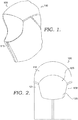
- FIG. 1 a hood including an exemplary hood adjusting mechanism 100 in accordance with aspects herein is illustrated from a perspective front view. While aspects discussed herein generally refer to hoods, it will be understood that aspects are not limited solely to hoods, but rather, may also be applied to any apparel item with a hood or a suitable opening. Further, the depictions in the figures are for exemplary purposes only and are in no way meant to limit the scope of the present invention. For instance, although the hood adjusting mechanism 100 is shown without an apparel item in FIGS. 1-7 , the hood adjusting mechanism 100 may be included as part of an apparel item such as a jacket, coat, hooded shirt or sweatshirt, or any other type of apparel having a hood.
- an apparel item such as a jacket, coat, hooded shirt or sweatshirt, or any other type of apparel having a hood.
- the hood adjusting mechanism 100 is not limited to use with a hood and may be included on any apparel item with a suitable opening.
- the term "apparel item” shall broadly refer to any item of clothing with a hood or suitable opening and encompass any terminology commonly known or used in the art such as article of clothing, clothing device, and the like.
- the term "as-worn position” or “worn” means the hood adjusting mechanism 100 as worn by a wearer standing in anatomical position as that term is known in the art. Further, terms such as “anterior,” “posterior,” “lateral,” “medial,” “superior,” “inferior,” and “mid-axillary” are meant to be given their common anatomical meanings and are used with respect to the hood adjusting mechanism 100 being in the as-worn position.
- affixing may comprise releasably affixing two items together via, for instance, buttons, snaps, zippers, hook-and-loop fasteners, and the like, and may also comprise permanently affixing two items together via, for example, stitching, bonding, adhesives, welding, and the like. Any and all aspects, and any variation thereof, are contemplated as being within the scope herein.
- the hood adjusting mechanism 100 may comprise a hood portion 110 configured to partially cover a head area of a wearer in an as-worn position.
- the hood portion 110 may comprise a front right panel and a left front panel that may be releasably secured to each other via a zipper-type mechanism 115.
- the hood adjusting mechanism 100 may be donned by the wearer by adjusting the zipper-type mechanism 115 to an unsecured position and then placing the hood portion 110 over the wearer's head.
- the hood adjusting mechanism 100 may not include the zipper-type mechanism 115 and may be donned simply by pulling the hood portion 110 over the wearer's head.
- the hood portion 110 may be constructed from any type of textile or non-textile material, such as a knitted material, a woven material, a film material, leather, non-woven, and the like.
- the material forming the hood portion 110 may be organic (e.g., cotton, wool, leather) or inorganic (e.g., nylon, polyester). Further, it is contemplated that combinations of materials may be implemented to construct one or more aspects of the hood portion 110.
- the exemplary hood adjusting mechanism 100 of FIG. 1 is depicted from the front, back, and sides, respectively.
- the hood portion 110 may comprise a generally circumferential opening 120, a first aperture 151, a second aperture 152, a first channel 131, and a second channel 132.
- the circumferential opening 120 may at least be defined by a right side portion 121 and a left side portion 122 and may be configured to form a perimeter edge 125 of the hood portion 110 around a wearer's face in an as-worn position.
- "generally circumferential" when used herein shall include a circular or oval shape like that of the wearer's face.
- the first aperture 151 may be positioned at a first aperture location 161 on a back side of the hood portion 110
- the second aperture 152 may be positioned at a second aperture location 162 on the back side of the hood portion 110.
- the first and second apertures 151, 152 may be partial perforations or holes in the hood portion 110 and may be configured to present openings to the first and second channels 131, 132.
- the hood portion 110 may be formed of an inner and an outer panel, and the first and second apertures 151, 152 may extend through the outer panel to provide a communication path to the first and second channels 131, 132 located between the inner and outer panels.
- first and second apertures 151, 152 may be engineered into a textile or material that forms the hood portion 110 or an apparel item, which includes the hood portion 110. Further, the first and second apertures 151, 152 may each include one hole or perforation presenting a shared opening for both the first and second channels 131, 132 or may each include two holes or perforations presenting separate openings for the first and second channels 131, 132.
- the first and second aperture locations 161, 162 may be positioned such that the first aperture location 161 is superior to and in vertical alignment with the second aperture location 162 when the hood adjusting mechanism 100 is in an as-worn position. Further, the vertical alignment of the first and second aperture locations 161, 162 may be along a midline of the hood portion 110.
- the first and second channels 131, 132 may form hollow, continuous or partially continuous voids about the hood portion 110 with openings formed by the first and second apertures 151, 152 and further, each may be configured to house a cord, string, or other cylindrical object. Moreover, the first and second channels 131, 132 may be positioned within the hood portion 110 and be formed by or between layers of material of the hood portion 110. In some aspects, the first and second channels 131, 132 may be integrally woven or knit into the hood portion 110 or may also be engineered into a textile or material that forms the hood portion 110 or an apparel item including the hood portion 110.
- the first and second channels 131, 132 may be externally affixed to the hood portion 110.
- the first and second channels 131, 132 may provide a pathway for a cord or string to extend about the hood portion 110 from the circumferential opening 120 to the first and second apertures 151, 152.
- the first channel 131 may comprise a first portion 141 and a second portion 142, with the first portion 141 extending from the first aperture location 161 to the right side portion 121 of the circumferential opening 120 and the second portion 142 extending from the second aperture location 162 to the right side portion 121 of the circumferential opening 120.
- the first portion 141 may extend in a substantially linear manner
- the second portion 142 may extend in a substantially curvilinear manner
- the second channel 132 may comprise a third portion 143 and a fourth portion 144.
- the third portion 143 may extend in a substantially linear manner from the first aperture location 161 to the left side portion 122 of the circumferential opening 120
- the fourth portion 144 may extend in a substantially curvilinear manner from the second aperture location 162 to the left side portion 122 of the circumferential opening 120.
- the first and third portions 141, 143 may extend in a generally horizontal manner, and the second and fourth portion 142, 144 may extend angularly downward along the hood portion 110.
- the second and fourth portions 142, 144 may respectively join with the first and third portions 141, 143 at a predetermined distance, variable between 1 cm and 15 cm, from the perimeter edge 125 of the circumferential opening 120.
- the second and fourth portions 142, 144 and the first and third portions 141, 143 may also join proximate to the circumferential opening 120 at a variable distance between .5 cm and 5 cm from the perimeter edge 125.
- the second and fourth portions 142, 144 and the first and third portions 141, 143 may be configured to respectively join at other locations relative to a total distance between the perimeter edge 125 and the first aperture location 161 and thus, may join at a third or a fourth of the total distance from the perimeter edge 125, which may include a variable distance between 5 cm and 15 cm from the perimeter edge 125.
- the second and fourth portions 142, 144 and the first and third portions 141, 143 may be configured to respectively join relative to wearer's head when the hood adjusting mechanism 100 is in and as-worn position.
- the second and fourth portions 142, 144 and the first and third portions 141, 143 may join at a location approximately positioned at a center of each respective side of the wearer's head when the hood adjusting mechanism 100 is in and as-worn position, which may include a variable distance between 10 cm and 20 cm from the perimeter edge 125. Furthermore, after being joined with the second and fourth portions 142, 144, the first and third portions 141, 143 may individually extend toward the perimeter edge 125 of the circumferential opening 120.
- the exemplary hood adjusting mechanism 100 may further comprise a tightening mechanism 170, a sheath 180, a first continuous cord 201, and a second continuous cord 202.
- the tightening mechanism 170 may be configured to releasably secure the first and second continuous cords 201, 202, either simultaneously or separately. Further, the tightening mechanism 170 may be positioned proximate to the first and second aperture locations 161, 162 and in an as-worn position, may be positioned vertically between the first and second aperture locations 161, 162. Additionally, the tightening mechanism 170 may be affixed to the hood portion 110.
- the tightening mechanism 170 may comprise a friction buckle although other types of buckles are contemplated herein such as tri-glides, ladder locks, cinch locks, cord-locks and the like.
- the tightening mechanism 170 may include a housing and a plunger, both of which may include at least one through-channel that may serve as a passage for the first and second continuous cords 201, 202.
- the housing and the plunger may be moveably coupled and may also include a spring configured to affect the alignment of the through-channels. For example, the plunger may be depressed by an external force that presses against the spring, bringing the through-channels toward alignment.
- the first and second continuous cords 201, 202 passing therethrough are more easily moveably than when the through-channels are less aligned.
- the through-channels may be positioned away from alignment, and the first and second continuous cords 201, 202 passing therethrough are secured and/or maintained.
- the housing, the plunger, and the spring may be configured such that the first and second continuous cords 201, 202 may be moveable in the through-channels in a first direction and also secured or prevented from moving in a second direction that is opposite the first direction.
- first and second continuous cords 201, 202 may be pulled by a wearer and moved in the first direction in the through-channels and once released by the wearer, the first and second continuous cords 201, 202 may be secured or prevented from moving backward or in the second direction in the through-channels.
- the tightening mechanism 170 may comprise a first cord lock 171 that may be positioned proximate to the first aperture location 161, and a second cord lock 172 that may be positioned proximate to the second aperture location 162.
- the first and second cord locks 171, 172 may be configured to operate independently and thus, a wearer may adjust the first cord lock 171 to releasably secure the first and second continuous cords 201, 202 without adjusting the second cord lock 172 and vice versa.
- the first and second cord locks 171, 172 may be affixed to the hood portion 110 at their respective positions.
- the tightening mechanism 170 may include multiple cord locks like the first and second cord lock 171, 172 or may only include a single cord lock which may be either the first cord lock 171 or the second cord lock 172 as well as any other similar cord lock mechanisms described herein.
- the sheath 180 may be configured to encase both the first and second continuous cords 201, 202 along a portion positioned exteriorly to the hood portion 110, thereby restricting the first and second continuous cords 201, 202 to an integral configuration. Accordingly, a wearer may concurrently tighten or pull the first and second continuous cords 201, 202 by imparting a pulling motion to the sheath 180.
- the sheath 180 may extend vertically between the first and second aperture locations 161, 162 and may be made of a material such as rubber, plastic, polyurethane, thermoplastic polyurethane, silicone, and the like. The sheath 180 may optionally be included with the hood adjusting mechanism 100.
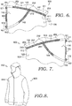
- FIGS. 6-7 the sides of the hood including the exemplary hood adjusting mechanism 100 of FIG. 1 with portions removed are depicted and an internal view of the first and second channels 131, 132 is provided as shown.
- the first and second continuous cords 201, 202 may be positioned within the first and second channels 131, 132 and extend therethrough. More specifically, the first continuous cord 201 may extend through the first and second portions 141, 142 of the first channel 131, exit at the first and second apertures 151, 152, and then further extend between the first and second apertures 151, 152.
- the second continuous cord 202 may extend through the third and fourth portions 143, 144 of the second channel 132, exit at the first and second apertures 151, 152, and then further extend between the first and second apertures 151, 152.
- the first and second continuous cords 201, 202 may, in exemplary aspects, be formed from materials having some degree of elasticity such as rubber, spandex, thermoplastic polyurethane (TPU), etc.
- the hood portion 110 may further comprise a first anchoring structure 111 and a second anchoring structure 112.
- the first anchoring structure 111 may be positioned within the first channel 131 and secured proximate the right side portion 121 of the circumferential opening 120
- the second anchoring structure 112 may be positioned within the second channel 132 and secured proximate the left side portion 122.
- the first and second anchoring structures 111, 112 may be secured within the first and second channels 131, 132 through mechanical pressure, stitching, bonding, adhesives, and the like.
- first and second anchoring structures 111, 112 may be formed of any materials that may form the hood portion 110 and may also be formed of other fabric material, a rubber material, a polyurethane or thermoplastic polyurethane material, and the like.
- first continuous cord 201 may be joined to the right side portion 121 of the circumferential opening 120 via the first anchoring structure 111
- second continuous cord 202 may be joined to the left side portion 122 of the circumferential opening 120 via the second anchoring structure 112.
- the first and second continuous cords 201, 202 may be secured to the first and second anchoring structures 111, 112, respectively, through mechanical pressure, stitching, bonding, adhesives, and the like.
- the first continuous cord 201 may comprise a first end 211, a second end 212, a first cord body 221, and a first junction 231 formed by an attachment of the second end 212 to the first cord body 221 via, for instance, stitching, bonding, adhesives, welding, and the like.
- the first cord body 221 may extend between the first and second ends 211, 212 and may include a first segment 241 extending from the first end 211 to the first junction 231 and a first loop 251 extending continuously between the first junction 231 and the second end 212.
- the first junction 231 may be positioned at a predetermined distance, variable between 1 cm and 10 cm, from the first end 211.
- the second continuous cord 202 may comprise a third end 213, a fourth end 214, a second cord body 222, and a second junction 232 formed by an attachment of the fourth end 214 to the second cord body 222 via, for instance, stitching, bonding, adhesives, welding, and the like.
- the second cord body 222 may extend between the third and fourth ends 213, 214 and may include a second segment 242 extending from the third end 213 to the second junction 232 and a second loop 252 extending continuously between the second junction 232 and the fourth end 214.
- the second junction 232 may be positioned at a predetermined distance, variable between 1 cm and 10 cm, from the third end 213.
- first and second channels 131, 132 and the first and second continuous cords 201, 202 may be configured in a complementary manner. Accordingly, the size and structure of the first and second channels 131, 132 may be slightly larger than the first and second continuous cords 201, 202 such that the first and second continuous cords 201 202 may freely move within the first and second channels 131, 132 but may be restricted in respect to the first and second channels 131, 132 location about the hood portion 110. Additionally, the first and second channels 131, 132 may reflect the particular components of the first and second continuous cords 201, 202.
- the first and second channels 131, 132 may divert from a single passageway near the circumferential opening 120 to a dual passageway to reflect differing components of the first and second continuous cords 201, 202 such as the first and second segments 241, 242 and the first and second loops 251, 252.
- the first and second junctions 231, 232 may be positioned at multiple predetermined distances from the first and third ends 211, 213, respectively, to reflect a configuration of the first and second channels 131, 132.
- Such predetermined distances from the first and third ends 211, 213, respectively, include distances variable between 1 cm and 15 cm, .5 cm and 5 cm, 5 cm and 15 cm, or 10 cm and 20 cm.
- first and second continuous cords 201, 202 may be respectively joined at the first and second ends 211, 212 and the third and fourth ends 213, 214 and may each include a single cord body extending between the respective ends.
- the first and second continuous cords 201, 202 may each include a single looped structure and thus, when extending through the first and second channels 131, 132, portions of the first and second continuous cords 201, 202 may overlap.
- two portions of each single cord body may extend together through a single passageway of the first and second channels 131, 132 proximate the circumferential opening 120 and separate to individually extend through a dual passageway of the respective first and second channels 131, 132.
- first and second continuous cords 201, 202 may each be secured to the circumferential opening 120 at a single location on opposing sides proximate the right and left side portions 121, 122 by the first and second anchoring structures 111, 112 and may also extend away from the perimeter edge 125 in a single direction via the first and second segments 241, 242.
- first and second continuous cords 201, 202 may extend away from the perimeter edge 125 in two different directions via the first and second loops 251, 252.
- the first and second loops 251, 252 may exit the first and second channels 131, 132 at two different points through the first and second apertures 151, 152, and may further extend outside of the hood portion 110 to form continuous loops.
- the first and second loops 251, 252 of the first and second continuous cords 201, 202 may be encased within the sheath 180 and may be releasably secured by the tightening mechanism 170. Accordingly, a wearer may exert, for instance, an outward and backward tension on the first and second loops 251, 252, directly or via the sheath 180, to simultaneously tighten the first and second continuous cords 201, 202 within the first and second channels 131, 132. This tension may be transmitted through the first and second loops 251, 252, to the first and second segments 241, 242 and further to the circumferential opening 120 proximate the right and left side portions 121, 122.
- the transmitted tension may pull the circumferential opening 120 downward over a wearer's face.
- the tension applied may be directed downward and may further pull a superior portion of the circumferential opening 120 over a wearer's face.
- the first and second channels 131, 132 may be positioned about the hood portion 110 the first and third portions 141, 143 may laterally direct the tension applied to the first aperture location 161, and the second and fourth portions 142, 144 may downwardly direct the tension applied to the second aperture location 162. Accordingly, the tension applied may be more uniformly directed throughout the hood portion 110 by the first and second channels 131, 132, and as a result, the hood portion 110 is pulled down in multiple directions over a wearer's head.
- the tightening mechanism 170 may help to maintain any tension applied to the exposed portions of the first and second loops 251, 252 (via, for instance, friction).
- the tightening mechanisms 170 may maintain the portions of the first and second continuous cords 201, 202 within the first and second channels 131, 132 at a fixed length after tension has been applied.
- the hood portion 110 and the circumferential opening 120 may be maintained over the wearer's head and face in a relatively static position until the tension is released.
- the apparel item 800 may comprise a body portion 810 configured to at least partially cover a torso area of a wearer when the apparel item is worn. More specifically, the apparel item 100 is in the form of a jacket/coat. However, it is contemplated herein that the apparel item 100 may take other forms such as a hoodie, a sleeveless jacket, a jacket with partial sleeves, a hoodie with partial sleeves or no sleeves, and the like.
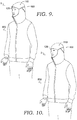
- FIGS. 9 and 10 illustrate the exemplary hood adjusting mechanism 100 included with the apparel item 800 in an as-worn position on a wearer.
- hood adjusting mechanism 100 is shown in a first position 1.
- the hood portion 110 extends over the wearer's head, and the circumferential opening 120 forms an opening around the wearer's face.
- the hood adjusting mechanism 100 is shown in a second position 2 in which the first and second continuous cords 201, 202 have been tightened and maintained by the tightening mechanism 170 as disclosed herein.
- the hood portion 110 is pulled tighter over the wearer's head, and the circumferential opening 120 is pulled downward over the wearer's face. More particularly, the posterior, superior and lateral portions of the hood portion 110 and the superior and lateral portions of the circumferential opening 120 are pulled down and tightened. However, the inferior portions of the hood portion 110 and the circumferential opening 120 remain loose providing more comfort to a wearer and also allowing a greater freedom of movement when the wearer needs to, for instance, turn his or her head.
Landscapes
- Engineering & Computer Science (AREA)
- Textile Engineering (AREA)
- Outer Garments And Coats (AREA)
- Details Of Garments (AREA)
- Professional, Industrial, Or Sporting Protective Garments (AREA)
Claims (15)
- Haubeneinstellmechanismus (100), umfassend: einen Haubenabschnitt (110), der konfiguriert ist, einen Kopfbereich eines Trägers in einer Trageposition zumindest teilweise zu bedecken, wobei der Haubenabschnitt (110) umfasst:eine im Allgemeinen umfängliche bzw. umlaufende Öffnung bzw. Aussparung (120), die zumindest durch einen rechten Seitenabschnitt (121) und einen linken Seitenabschnitt (122) definiert ist,eine erste Öffnung (151), die an einer ersten Öffnungsstelle (161) an einer Rückseite des Haubenabschnitts (110) positioniert ist,eine zweite Öffnung (152), die an einer zweiten Öffnungsstelle (162) an der Rückseite des Haubenabschnitts (110) positioniert ist,einen ersten Kanal (131) mit einem ersten Abschnitt (141), der sich von der ersten Öffnungsstelle (161) zu dem rechten Seitenabschnitt (121) der Umfangsaussparung (120) erstreckt, und einem zweiten Abschnitt (142), der sich von der zweiten Öffnungsstelle (162) zu dem rechten Seitenabschnitt (121) der Umfangsaussparung (120) erstreckt, undeinen zweiten Kanal (132) mit einem dritten Abschnitt (143), der sich von der ersten Öffnungsstelle (161) zu dem linken Seitenabschnitt (122) der Umfangsaussparung (120) erstreckt, und einem vierten Abschnitt (144), der sich von der zweiten Öffnungsstelle (162) zu dem linken Seitenabschnitt (122) der Umfangsaussparung (120) erstreckt,eine erste durchgehende Schnur bzw. Kordel (201), die sich durch den ersten und zweiten Abschnitt (141, 142) des ersten Kanals (131) erstreckt und an der ersten und zweiten Öffnung (151, 152) austritt, wobei sich die erste durchgehende Schnur (201) ferner zwischen der ersten und zweiten Öffnung (151, 152) erstreckt;eine zweite durchgehende Schnur bzw. Kordel (202), die sich durch den dritten und vierten Abschnitt (143, 144) des zweiten Kanals (132) erstreckt und an der ersten und zweiten Öffnung (151, 152) austritt, wobei sich die zweite durchgehende Schnur (202) ferner zwischen der ersten und zweiten Öffnung (151, 152) erstreckt; undeinen Festziehmechanismus (170) in der Nähe der ersten und zweiten Öffnungsstelle (161, 162), wobei der Festziehmechanismus (170) konfiguriert ist, die erste durchgehende Schnur (201) und die zweite durchgehende Schnur (202) lösbar zu befestigen.
- Haubeneinstellmechanismus (100) nach Anspruch 1, wobei die erste durchgehende Schnur (201) zumindest ein erstes Ende (211) umfasst und die zweite durchgehende Schnur (202) zumindest ein drittes Ende (213) umfasst, und wobei das erste Ende (211) über eine erste Verankerungsstruktur (111) an dem rechten Seitenabschnitt (121) der Umfangsaussparung (120) befestigt ist und das dritte Ende (213) über eine zweite Verankerungsstruktur (112) an dem linken Seitenabschnitt (122) der Umfangsaussparung (120) befestigt ist.
- Haubeneinstellmechanismus (100) nach Anspruch 2, wobei sich die erste Verankerungsstruktur (111) innerhalb des ersten Kanals (131) in der Nähe des rechten Seitenabschnitts (121) der Umfangsaussparung (120) befindet und sich die zweite Verankerungsstruktur (112) innerhalb des zweiten Kanals (132) in der Nähe des linken Seitenabschnitts (122) der Umfangsaussparung (120) befindet.
- Haubeneinstellmechanismus (100) nach Anspruch 2, wobei die erste durchgehende Schnur (201) ferner einen ersten Kordel- bzw. Schnurkörper (221) und ein zweites Ende (212) umfasst und die zweite durchgehende Schnur (202) ferner einen zweiten Kordel- bzw. Schnurkörper (222) und ein viertes Ende (214) umfasst, und wobei das zweite Ende (212) an dem ersten Schnurkörper (221) in einer vorbestimmten Länge von dem ersten Ende (211) angebracht ist und das vierte Ende (214) an dem zweiten Schnurkörper (222) in einer vorbestimmten Länge von dem dritten Ende (213) angebracht ist.
- Haubeneinstellmechanismus (100) nach Anspruch 3, wobei der zweite Abschnitt (142) mit dem ersten Abschnitt (141) zwischen der ersten Verankerungsstruktur (111) und der ersten Öffnungsstelle (161) verbunden ist und wobei der vierte Abschnitt (144) mit dem dritten Abschnitt (143) zwischen der zweiten Verankerungsstruktur (112) und der ersten Öffnungsstelle (161) verbunden ist.
- Haubeneinstellmechanismus (100) nach Anspruch 1, wobei die erste Öffnungsstelle (161) superior zu bzw. über der zweiten Öffnungsstelle (162) auf der Rückseite des Haubenabschnitts (110) in der Trageposition positioniert ist.
- Haubeneinstellmechanismus (100) nach Anspruch 6, wobei die erste Öffnungsstelle (161) und die zweite Öffnungsstelle (162) in einer im Wesentlichen vertikalen Ausrichtung auf der Rückseite des Haubenabschnitts (110) in einer Trageposition sind,
wobei der Festziehmechanismus (170) optional eine erste Kordel- bzw. Schnurverriegelung (171), die angrenzend an bzw. benachbart zu der ersten Öffnungsstelle (161) positioniert ist, und eine zweite Kordel- bzw. Schnurverriegelung (172) umfasst, die angrenzend an bzw. benachbart zu der zweiten Öffnungsstelle (162) positioniert ist, und zwar in einer Trageposition. - Haubeneinstellmechanismus (100) nach Anspruch 1, wobei die erste durchgehende Schnur (201) und die zweite durchgehende Schnur (202) aus einem Material mit elastischen Eigenschaften bestehen.
- Kleidungsstück (800) mit einem Haubeneinstellmechanismus (100), wobei das Kleidungsstück (800) umfasst: einen Körperabschnitt (810), der konfiguriert ist, einen Torsobereich eines Trägers zumindest teilweise zu bedecken, wenn das Kleidungsstück (800) getragen wird; einen Haubenabschnitt (110), der an dem Körperabschnitt (810) befestigt ist und konfiguriert ist, einen Kopfbereich eines Trägers in einer Trageposition zumindest teilweise zu bedecken, wobei der Haubenabschnitt (110) umfasst:eine im Allgemeinen umfängliche bzw. umlaufende Öffnung bzw. Aussparung (120), die zumindest durch einen rechten Seitenabschnitt (121) und einen linken Seitenabschnitt (122) definiert ist, eine erste Öffnung (151), die an einer ersten Öffnungsstelle (161) an einer Rückseite des Haubenabschnitts (110) positioniert ist,eine zweite Öffnung (152), die an einer zweiten Öffnungsstelle (162) an der Rückseite des Haubenabschnitts (110) positioniert ist,einen ersten Kanal (131) mit einem ersten Abschnitt (141), der sich von der ersten Öffnungsstelle (161) zu dem rechten Seitenabschnitt (121) der Umfangsaussparung (120) erstreckt, undeinem zweiten Abschnitt (142), der sich von der zweiten Öffnungsstelle (162) zu dem rechten Seitenabschnitt (121) der Umfangsaussparung (120) erstreckt, und einen zweiten Kanal (132) mit einem dritten Abschnitt (143), der sich von der ersten Öffnungsstelle (161) zu dem linken Seitenabschnitt (122) der Umfangsaussparung (120) erstreckt, und einem vierten Abschnitt (144), der sich von der zweiten Öffnungsstelle (162) zu dem linken Seitenabschnitt (122) der Umfangsaussparung (120) erstreckt,eine erste durchgehende Schnur bzw. Kordel (201), die sich durch den ersten und zweiten Abschnitt (141, 142) des ersten Kanals (131) erstreckt und an der ersten und zweiten Öffnung (151, 152) austritt, wobei sich die erste durchgehende Schnur (201) ferner zwischen der ersten und zweiten Öffnung (151, 152) erstreckt;eine zweite durchgehende Schnur bzw. Kordel (202), die sich durch den dritten und vierten Abschnitt (143, 144) des zweiten Kanals (132) erstreckt und an der ersten und zweiten Öffnung (151, 152) austritt, wobei sich die zweite durchgehende Schnur (202) ferner zwischen der ersten und zweiten Öffnung (151, 152) erstreckt; undeinen Festziehmechanismus (170) in der Nähe der ersten und zweiten Öffnungsstelle (161, 162), wobei der Festziehmechanismus (170) konfiguriert ist, die erste durchgehende Schnur (201) und die zweite durchgehende Schnur (202) lösbar zu befestigen.
- Kleidungsstück (800) nach Anspruch 9, wobei die erste durchgehende Schnur (201) ein erstes Ende (211) umfasst und die zweite durchgehende Schnur (202) ein drittes Ende (213) umfasst, und wobei das erste Ende (211) über eine erste Verankerungsstruktur (111) an dem rechten Seitenabschnitt (121) der Umfangsaussparung (120) befestigt ist und das dritte Ende (213) über eine zweite Verankerungsstruktur (112) an dem linken Seitenabschnitt (122) der Umfangsaussparung (120) befestigt ist.
- Kleidungsstück (800) nach Anspruch 10, wobei sich die erste Verankerungsstruktur (111) innerhalb des ersten Kanals (131) in der Nähe des rechten Seitenabschnitts (121) der Umfangsaussparung (120) befindet und sich die zweite Verankerungsstruktur (112) innerhalb des zweiten Kanals (132) in der Nähe des linken Seitenabschnitts (122) der Umfangsaussparung (120) befindet.
- Kleidungsstück (800) nach Anspruch 11, wobei der zweite Abschnitt (142) mit dem ersten Abschnitt (141) zwischen der ersten Verankerungsstruktur (111) und der ersten Öffnungsstelle (161) verbunden ist und wobei der vierte Abschnitt (144) mit dem dritten Abschnitt (143) zwischen der zweiten Verankerungsstruktur (112) und der ersten Öffnungsstelle (161) verbunden ist.
- Kleidungsstück (800) nach Anspruch 9, wobei die erste Öffnungsstelle (161) superior zu bzw. über der zweiten Öffnungsstelle (162) auf der Rückseite des Haubenabschnitts (110) in der Trageposition positioniert ist.
- Bekleidungsgegenstand (800) nach Anspruch 13, wobei die erste Öffnungsstelle (161) und die zweite Öffnungsstelle (162) in einer im Wesentlichen vertikalen Ausrichtung auf der Rückseite des Haubenabschnitts (110) in einer Trageposition sind,
wobei der Festziehmechanismus (170) optional eine erste Kordel- bzw. Schnurverriegelung (171), die angrenzend an bzw. benachbart zu der ersten Öffnungsstelle (161) positioniert ist, und eine zweite Kordel- bzw. Schnurverriegelung (172) umfasst, die angrenzend an bzw. benachbart zu der zweiten Öffnungsstelle (162) positioniert ist, und zwar in einer Trageposition. - Kleidungsstück (800) nach Anspruch 9, wobei die erste durchgehende Schnur (201) und die zweite durchgehende Schnur (202) aus einem Material mit elastischen Eigenschaften bestehen.
Applications Claiming Priority (3)
| Application Number | Priority Date | Filing Date | Title |
|---|---|---|---|
| US201662377034P | 2016-08-19 | 2016-08-19 | |
| US15/679,823 US10893715B2 (en) | 2016-08-19 | 2017-08-17 | Hood adjusting mechanism |
| PCT/US2017/047571 WO2018035440A1 (en) | 2016-08-19 | 2017-08-18 | Hood adjusting mechanism |
Publications (2)
| Publication Number | Publication Date |
|---|---|
| EP3500124A1 EP3500124A1 (de) | 2019-06-26 |
| EP3500124B1 true EP3500124B1 (de) | 2021-01-27 |
Family
ID=61190604
Family Applications (1)
| Application Number | Title | Priority Date | Filing Date |
|---|---|---|---|
| EP17758404.2A Active EP3500124B1 (de) | 2016-08-19 | 2017-08-18 | Haubenanpassmechanismus |
Country Status (4)
| Country | Link |
|---|---|
| US (1) | US10893715B2 (de) |
| EP (1) | EP3500124B1 (de) |
| CN (1) | CN109640725B (de) |
| WO (1) | WO2018035440A1 (de) |
Families Citing this family (10)
| Publication number | Priority date | Publication date | Assignee | Title |
|---|---|---|---|---|
| US11717037B2 (en) | 2018-06-04 | 2023-08-08 | Peter Driessen | Safety garment with integrated earplugs |
| USD930951S1 (en) | 2018-06-29 | 2021-09-21 | Ramel Curry | Garment |
| US20200000153A1 (en) * | 2018-06-29 | 2020-01-02 | Ramel Curry | Workout garment |
| US11497261B2 (en) * | 2019-03-08 | 2022-11-15 | SteelGorillas LLC | Dust hood |
| USD885014S1 (en) | 2019-03-14 | 2020-05-26 | Nike, Inc. | Jacket |
| USD874094S1 (en) * | 2019-03-14 | 2020-02-04 | Nike, Inc. | Jacket |
| USD955696S1 (en) | 2020-04-09 | 2022-06-28 | Wind & Stitch LLC | Garment that converts to a cushion |
| US12349753B2 (en) * | 2022-06-30 | 2025-07-08 | Kuiu, Llc | Jacket with detachable hood |
| US20250194726A1 (en) * | 2023-12-14 | 2025-06-19 | Acushnet Company | Hood cinch system |
| US20250228307A1 (en) * | 2024-01-12 | 2025-07-17 | Harley-Davidson Motor Company, Inc. | Hooded garment having a multifunctional riding hood |
Family Cites Families (23)
| Publication number | Priority date | Publication date | Assignee | Title |
|---|---|---|---|---|
| US4334325A (en) | 1980-10-23 | 1982-06-15 | Joseph Walkuski | Garment hood |
| US5369809A (en) * | 1993-05-13 | 1994-12-06 | Nike, Inc. | Adjustable hood system |
| JP3724824B2 (ja) | 1994-03-14 | 2005-12-07 | 株式会社ゴールドウイン | 雨衣・防寒衣用フード |
| DE9404990U1 (de) | 1994-03-23 | 1995-07-27 | Gore W L & Ass Gmbh | Kapuze |
| US5832538A (en) | 1997-03-13 | 1998-11-10 | Williams; Kevin S. | Protective headwear |
| US6023787A (en) | 1998-09-09 | 2000-02-15 | French; Katherina Grace | Hood with faceguard |
| US6442763B1 (en) | 2000-01-10 | 2002-09-03 | Jon C. Larson | Insulating hood |
| US6370692B1 (en) | 2000-06-07 | 2002-04-16 | Lacrosse Footwear, Inc. | Convertible outdoor garmet |
| JP4463386B2 (ja) * | 2000-06-21 | 2010-05-19 | グローブライド株式会社 | 雨衣・防寒衣用フード |
| US6374418B1 (en) * | 2000-11-09 | 2002-04-23 | Salomon, S.A. | Adjustable hood system |
| WO2002058495A1 (en) | 2001-01-24 | 2002-08-01 | Arc'teryx Equipment Inc. | Jacket with adjustable hood |
| CA2332201A1 (en) | 2001-01-24 | 2002-07-24 | Arc'teryx Equipment Inc. | Outdoor jacket |
| US20050241045A1 (en) | 2003-05-30 | 2005-11-03 | Tolton Gary A | Adjustment system for rotatable hood of outerwear garment |
| US20050108804A1 (en) * | 2003-11-24 | 2005-05-26 | Spyder Active Sports, Inc. | Adjustable Hood System |
| US7380286B1 (en) | 2003-12-23 | 2008-06-03 | Bryant Sr Frank D | Head covering with unobstructed vision |
| GB2419803A (en) * | 2004-11-09 | 2006-05-10 | Berghaus Ltd | Length adjusters for garments and other articles |
| FR2902296B1 (fr) | 2006-06-14 | 2008-08-22 | Guy Cotten Sa Ets | Capuche a serrage de tete, vetement de haut de corps comportant une telle capuche |
| US20100064417A1 (en) | 2008-09-15 | 2010-03-18 | Fruge Paul E | Hunters Hood with Adjustable Face Opening |
| KR101162155B1 (ko) * | 2009-08-05 | 2012-07-04 | 강경달 | 시야가림 방지용 모자 |
| JP2011122268A (ja) * | 2009-12-10 | 2011-06-23 | Goldwin Inc | 襠と、当該襠を開閉する襠開閉機構とを備えるフード、及び当該フードを備える衣服 |
| US8438665B2 (en) | 2011-08-01 | 2013-05-14 | Gander Mountain Company | Hooded garment with adjustable hood side portions and method of adjusting the same |
| US20140317829A1 (en) | 2013-04-27 | 2014-10-30 | Sirena Rolfe | Hood Apparatus |
| US11134731B2 (en) * | 2017-03-24 | 2021-10-05 | Zhik Pty Ltd | Protective hood with improved vision for waterproof marine garments |
-
2017
- 2017-08-17 US US15/679,823 patent/US10893715B2/en active Active
- 2017-08-18 WO PCT/US2017/047571 patent/WO2018035440A1/en not_active Ceased
- 2017-08-18 CN CN201780050936.7A patent/CN109640725B/zh active Active
- 2017-08-18 EP EP17758404.2A patent/EP3500124B1/de active Active
Non-Patent Citations (1)
| Title |
|---|
| None * |
Also Published As
| Publication number | Publication date |
|---|---|
| US20180049499A1 (en) | 2018-02-22 |
| WO2018035440A1 (en) | 2018-02-22 |
| CN109640725A (zh) | 2019-04-16 |
| EP3500124A1 (de) | 2019-06-26 |
| CN109640725B (zh) | 2021-06-29 |
| US10893715B2 (en) | 2021-01-19 |
Similar Documents
| Publication | Publication Date | Title |
|---|---|---|
| EP3500124B1 (de) | Haubenanpassmechanismus | |
| US10219553B2 (en) | System and method of adjusting the fit of clothing | |
| US9320307B2 (en) | Garment with adjustable lacing arrangement | |
| US4649574A (en) | Garment closure | |
| US20200229516A1 (en) | System and method of adjusting the fit of clothing | |
| US20100088795A1 (en) | Combat uniform | |
| KR101958186B1 (ko) | 끈 조절고리부를 포함하는 상의 | |
| US10786052B2 (en) | Articles incorporating a coupled slider system | |
| US20210037896A1 (en) | Activewear and methods of use and manufacture thereof | |
| CN109068774A (zh) | 用于服饰物品的通风镶件 | |
| US20210260467A1 (en) | Securing garment for a shoulder-pad system | |
| CN104507339A (zh) | 以包括背带功能的方式制作的上衣 | |
| CN109069911B (zh) | 用于肩部衬垫系统的分立肩部袖筒以及其穿戴方法 | |
| EP2441336B1 (de) | Beinabdeckung | |
| US20140096304A1 (en) | Internally Belted Coveralls | |
| US20230270184A1 (en) | Activewear and methods of use and manufacture thereof | |
| JP4940320B2 (ja) | 雪除け防具 | |
| US20240341383A1 (en) | Pair of trousers comprising a waistband system | |
| CA2999738A1 (en) | System and method of adjusting the fit of clothing | |
| KR100863484B1 (ko) | 허리 사이즈가 조절되는 경찰복 바지 | |
| US20200130790A1 (en) | Life jacket with integrated sleeves | |
| JP2020020049A (ja) | 下半身用衣類 | |
| US20070204379A1 (en) | Garment with end closing means | |
| JP6798837B2 (ja) | ズボン | |
| JP3213033U (ja) | 防護衣 |
Legal Events
| Date | Code | Title | Description |
|---|---|---|---|
| STAA | Information on the status of an ep patent application or granted ep patent |
Free format text: STATUS: UNKNOWN |
|
| STAA | Information on the status of an ep patent application or granted ep patent |
Free format text: STATUS: THE INTERNATIONAL PUBLICATION HAS BEEN MADE |
|
| PUAI | Public reference made under article 153(3) epc to a published international application that has entered the european phase |
Free format text: ORIGINAL CODE: 0009012 |
|
| STAA | Information on the status of an ep patent application or granted ep patent |
Free format text: STATUS: REQUEST FOR EXAMINATION WAS MADE |
|
| 17P | Request for examination filed |
Effective date: 20190131 |
|
| AK | Designated contracting states |
Kind code of ref document: A1 Designated state(s): AL AT BE BG CH CY CZ DE DK EE ES FI FR GB GR HR HU IE IS IT LI LT LU LV MC MK MT NL NO PL PT RO RS SE SI SK SM TR |
|
| AX | Request for extension of the european patent |
Extension state: BA ME |
|
| DAV | Request for validation of the european patent (deleted) | ||
| DAX | Request for extension of the european patent (deleted) | ||
| GRAJ | Information related to disapproval of communication of intention to grant by the applicant or resumption of examination proceedings by the epo deleted |
Free format text: ORIGINAL CODE: EPIDOSDIGR1 |
|
| GRAP | Despatch of communication of intention to grant a patent |
Free format text: ORIGINAL CODE: EPIDOSNIGR1 |
|
| GRAP | Despatch of communication of intention to grant a patent |
Free format text: ORIGINAL CODE: EPIDOSNIGR1 |
|
| STAA | Information on the status of an ep patent application or granted ep patent |
Free format text: STATUS: GRANT OF PATENT IS INTENDED |
|
| INTG | Intention to grant announced |
Effective date: 20200430 |
|
| GRAJ | Information related to disapproval of communication of intention to grant by the applicant or resumption of examination proceedings by the epo deleted |
Free format text: ORIGINAL CODE: EPIDOSDIGR1 |
|
| GRAP | Despatch of communication of intention to grant a patent |
Free format text: ORIGINAL CODE: EPIDOSNIGR1 |
|
| STAA | Information on the status of an ep patent application or granted ep patent |
Free format text: STATUS: REQUEST FOR EXAMINATION WAS MADE |
|
| GRAJ | Information related to disapproval of communication of intention to grant by the applicant or resumption of examination proceedings by the epo deleted |
Free format text: ORIGINAL CODE: EPIDOSDIGR1 |
|
| INTG | Intention to grant announced |
Effective date: 20200619 |
|
| INTC | Intention to grant announced (deleted) | ||
| GRAP | Despatch of communication of intention to grant a patent |
Free format text: ORIGINAL CODE: EPIDOSNIGR1 |
|
| STAA | Information on the status of an ep patent application or granted ep patent |
Free format text: STATUS: GRANT OF PATENT IS INTENDED |
|
| GRAJ | Information related to disapproval of communication of intention to grant by the applicant or resumption of examination proceedings by the epo deleted |
Free format text: ORIGINAL CODE: EPIDOSDIGR1 |
|
| GRAP | Despatch of communication of intention to grant a patent |
Free format text: ORIGINAL CODE: EPIDOSNIGR1 |
|
| INTG | Intention to grant announced |
Effective date: 20200728 |
|
| INTG | Intention to grant announced |
Effective date: 20200820 |
|
| GRAS | Grant fee paid |
Free format text: ORIGINAL CODE: EPIDOSNIGR3 |
|
| GRAA | (expected) grant |
Free format text: ORIGINAL CODE: 0009210 |
|
| STAA | Information on the status of an ep patent application or granted ep patent |
Free format text: STATUS: THE PATENT HAS BEEN GRANTED |
|
| AK | Designated contracting states |
Kind code of ref document: B1 Designated state(s): AL AT BE BG CH CY CZ DE DK EE ES FI FR GB GR HR HU IE IS IT LI LT LU LV MC MK MT NL NO PL PT RO RS SE SI SK SM TR |
|
| REG | Reference to a national code |
Ref country code: GB Ref legal event code: FG4D |
|
| REG | Reference to a national code |
Ref country code: CH Ref legal event code: EP |
|
| REG | Reference to a national code |
Ref country code: DE Ref legal event code: R082 Ref document number: 602017032109 Country of ref document: DE Representative=s name: MUELLER-BORE & PARTNER PATENTANWAELTE PARTG MB, DE |
|
| REG | Reference to a national code |
Ref country code: AT Ref legal event code: REF Ref document number: 1357551 Country of ref document: AT Kind code of ref document: T Effective date: 20210215 |
|
| REG | Reference to a national code |
Ref country code: IE Ref legal event code: FG4D |
|
| REG | Reference to a national code |
Ref country code: DE Ref legal event code: R096 Ref document number: 602017032109 Country of ref document: DE |
|
| REG | Reference to a national code |
Ref country code: NL Ref legal event code: MP Effective date: 20210127 |
|
| REG | Reference to a national code |
Ref country code: LT Ref legal event code: MG9D |
|
| REG | Reference to a national code |
Ref country code: AT Ref legal event code: MK05 Ref document number: 1357551 Country of ref document: AT Kind code of ref document: T Effective date: 20210127 |
|
| PG25 | Lapsed in a contracting state [announced via postgrant information from national office to epo] |
Ref country code: BG Free format text: LAPSE BECAUSE OF FAILURE TO SUBMIT A TRANSLATION OF THE DESCRIPTION OR TO PAY THE FEE WITHIN THE PRESCRIBED TIME-LIMIT Effective date: 20210427 Ref country code: LT Free format text: LAPSE BECAUSE OF FAILURE TO SUBMIT A TRANSLATION OF THE DESCRIPTION OR TO PAY THE FEE WITHIN THE PRESCRIBED TIME-LIMIT Effective date: 20210127 Ref country code: FI Free format text: LAPSE BECAUSE OF FAILURE TO SUBMIT A TRANSLATION OF THE DESCRIPTION OR TO PAY THE FEE WITHIN THE PRESCRIBED TIME-LIMIT Effective date: 20210127 Ref country code: GR Free format text: LAPSE BECAUSE OF FAILURE TO SUBMIT A TRANSLATION OF THE DESCRIPTION OR TO PAY THE FEE WITHIN THE PRESCRIBED TIME-LIMIT Effective date: 20210428 Ref country code: HR Free format text: LAPSE BECAUSE OF FAILURE TO SUBMIT A TRANSLATION OF THE DESCRIPTION OR TO PAY THE FEE WITHIN THE PRESCRIBED TIME-LIMIT Effective date: 20210127 Ref country code: PT Free format text: LAPSE BECAUSE OF FAILURE TO SUBMIT A TRANSLATION OF THE DESCRIPTION OR TO PAY THE FEE WITHIN THE PRESCRIBED TIME-LIMIT Effective date: 20210527 Ref country code: NO Free format text: LAPSE BECAUSE OF FAILURE TO SUBMIT A TRANSLATION OF THE DESCRIPTION OR TO PAY THE FEE WITHIN THE PRESCRIBED TIME-LIMIT Effective date: 20210427 |
|
| PG25 | Lapsed in a contracting state [announced via postgrant information from national office to epo] |
Ref country code: SE Free format text: LAPSE BECAUSE OF FAILURE TO SUBMIT A TRANSLATION OF THE DESCRIPTION OR TO PAY THE FEE WITHIN THE PRESCRIBED TIME-LIMIT Effective date: 20210127 Ref country code: LV Free format text: LAPSE BECAUSE OF FAILURE TO SUBMIT A TRANSLATION OF THE DESCRIPTION OR TO PAY THE FEE WITHIN THE PRESCRIBED TIME-LIMIT Effective date: 20210127 Ref country code: PL Free format text: LAPSE BECAUSE OF FAILURE TO SUBMIT A TRANSLATION OF THE DESCRIPTION OR TO PAY THE FEE WITHIN THE PRESCRIBED TIME-LIMIT Effective date: 20210127 Ref country code: RS Free format text: LAPSE BECAUSE OF FAILURE TO SUBMIT A TRANSLATION OF THE DESCRIPTION OR TO PAY THE FEE WITHIN THE PRESCRIBED TIME-LIMIT Effective date: 20210127 Ref country code: AT Free format text: LAPSE BECAUSE OF FAILURE TO SUBMIT A TRANSLATION OF THE DESCRIPTION OR TO PAY THE FEE WITHIN THE PRESCRIBED TIME-LIMIT Effective date: 20210127 |
|
| PG25 | Lapsed in a contracting state [announced via postgrant information from national office to epo] |
Ref country code: IS Free format text: LAPSE BECAUSE OF FAILURE TO SUBMIT A TRANSLATION OF THE DESCRIPTION OR TO PAY THE FEE WITHIN THE PRESCRIBED TIME-LIMIT Effective date: 20210527 |
|
| REG | Reference to a national code |
Ref country code: DE Ref legal event code: R097 Ref document number: 602017032109 Country of ref document: DE |
|
| PG25 | Lapsed in a contracting state [announced via postgrant information from national office to epo] |
Ref country code: EE Free format text: LAPSE BECAUSE OF FAILURE TO SUBMIT A TRANSLATION OF THE DESCRIPTION OR TO PAY THE FEE WITHIN THE PRESCRIBED TIME-LIMIT Effective date: 20210127 Ref country code: CZ Free format text: LAPSE BECAUSE OF FAILURE TO SUBMIT A TRANSLATION OF THE DESCRIPTION OR TO PAY THE FEE WITHIN THE PRESCRIBED TIME-LIMIT Effective date: 20210127 Ref country code: SM Free format text: LAPSE BECAUSE OF FAILURE TO SUBMIT A TRANSLATION OF THE DESCRIPTION OR TO PAY THE FEE WITHIN THE PRESCRIBED TIME-LIMIT Effective date: 20210127 |
|
| PG25 | Lapsed in a contracting state [announced via postgrant information from national office to epo] |
Ref country code: RO Free format text: LAPSE BECAUSE OF FAILURE TO SUBMIT A TRANSLATION OF THE DESCRIPTION OR TO PAY THE FEE WITHIN THE PRESCRIBED TIME-LIMIT Effective date: 20210127 Ref country code: SK Free format text: LAPSE BECAUSE OF FAILURE TO SUBMIT A TRANSLATION OF THE DESCRIPTION OR TO PAY THE FEE WITHIN THE PRESCRIBED TIME-LIMIT Effective date: 20210127 Ref country code: DK Free format text: LAPSE BECAUSE OF FAILURE TO SUBMIT A TRANSLATION OF THE DESCRIPTION OR TO PAY THE FEE WITHIN THE PRESCRIBED TIME-LIMIT Effective date: 20210127 |
|
| PLBE | No opposition filed within time limit |
Free format text: ORIGINAL CODE: 0009261 |
|
| STAA | Information on the status of an ep patent application or granted ep patent |
Free format text: STATUS: NO OPPOSITION FILED WITHIN TIME LIMIT |
|
| 26N | No opposition filed |
Effective date: 20211028 |
|
| PG25 | Lapsed in a contracting state [announced via postgrant information from national office to epo] |
Ref country code: ES Free format text: LAPSE BECAUSE OF FAILURE TO SUBMIT A TRANSLATION OF THE DESCRIPTION OR TO PAY THE FEE WITHIN THE PRESCRIBED TIME-LIMIT Effective date: 20210127 Ref country code: AL Free format text: LAPSE BECAUSE OF FAILURE TO SUBMIT A TRANSLATION OF THE DESCRIPTION OR TO PAY THE FEE WITHIN THE PRESCRIBED TIME-LIMIT Effective date: 20210127 |
|
| PG25 | Lapsed in a contracting state [announced via postgrant information from national office to epo] |
Ref country code: SI Free format text: LAPSE BECAUSE OF FAILURE TO SUBMIT A TRANSLATION OF THE DESCRIPTION OR TO PAY THE FEE WITHIN THE PRESCRIBED TIME-LIMIT Effective date: 20210127 |
|
| REG | Reference to a national code |
Ref country code: CH Ref legal event code: PL |
|
| PG25 | Lapsed in a contracting state [announced via postgrant information from national office to epo] |
Ref country code: MC Free format text: LAPSE BECAUSE OF FAILURE TO SUBMIT A TRANSLATION OF THE DESCRIPTION OR TO PAY THE FEE WITHIN THE PRESCRIBED TIME-LIMIT Effective date: 20210127 |
|
| REG | Reference to a national code |
Ref country code: BE Ref legal event code: MM Effective date: 20210831 |
|
| PG25 | Lapsed in a contracting state [announced via postgrant information from national office to epo] |
Ref country code: LI Free format text: LAPSE BECAUSE OF NON-PAYMENT OF DUE FEES Effective date: 20210831 Ref country code: IT Free format text: LAPSE BECAUSE OF FAILURE TO SUBMIT A TRANSLATION OF THE DESCRIPTION OR TO PAY THE FEE WITHIN THE PRESCRIBED TIME-LIMIT Effective date: 20210127 Ref country code: CH Free format text: LAPSE BECAUSE OF NON-PAYMENT OF DUE FEES Effective date: 20210831 |
|
| PG25 | Lapsed in a contracting state [announced via postgrant information from national office to epo] |
Ref country code: IS Free format text: LAPSE BECAUSE OF FAILURE TO SUBMIT A TRANSLATION OF THE DESCRIPTION OR TO PAY THE FEE WITHIN THE PRESCRIBED TIME-LIMIT Effective date: 20210527 Ref country code: LU Free format text: LAPSE BECAUSE OF NON-PAYMENT OF DUE FEES Effective date: 20210818 |
|
| PG25 | Lapsed in a contracting state [announced via postgrant information from national office to epo] |
Ref country code: IE Free format text: LAPSE BECAUSE OF NON-PAYMENT OF DUE FEES Effective date: 20210818 Ref country code: BE Free format text: LAPSE BECAUSE OF NON-PAYMENT OF DUE FEES Effective date: 20210831 |
|
| P01 | Opt-out of the competence of the unified patent court (upc) registered |
Effective date: 20230515 |
|
| PG25 | Lapsed in a contracting state [announced via postgrant information from national office to epo] |
Ref country code: NL Free format text: LAPSE BECAUSE OF NON-PAYMENT OF DUE FEES Effective date: 20210127 Ref country code: CY Free format text: LAPSE BECAUSE OF FAILURE TO SUBMIT A TRANSLATION OF THE DESCRIPTION OR TO PAY THE FEE WITHIN THE PRESCRIBED TIME-LIMIT Effective date: 20210127 |
|
| PG25 | Lapsed in a contracting state [announced via postgrant information from national office to epo] |
Ref country code: HU Free format text: LAPSE BECAUSE OF FAILURE TO SUBMIT A TRANSLATION OF THE DESCRIPTION OR TO PAY THE FEE WITHIN THE PRESCRIBED TIME-LIMIT; INVALID AB INITIO Effective date: 20170818 |
|
| PG25 | Lapsed in a contracting state [announced via postgrant information from national office to epo] |
Ref country code: MK Free format text: LAPSE BECAUSE OF FAILURE TO SUBMIT A TRANSLATION OF THE DESCRIPTION OR TO PAY THE FEE WITHIN THE PRESCRIBED TIME-LIMIT Effective date: 20210127 |
|
| PG25 | Lapsed in a contracting state [announced via postgrant information from national office to epo] |
Ref country code: TR Free format text: LAPSE BECAUSE OF FAILURE TO SUBMIT A TRANSLATION OF THE DESCRIPTION OR TO PAY THE FEE WITHIN THE PRESCRIBED TIME-LIMIT Effective date: 20210127 |
|
| PG25 | Lapsed in a contracting state [announced via postgrant information from national office to epo] |
Ref country code: MT Free format text: LAPSE BECAUSE OF FAILURE TO SUBMIT A TRANSLATION OF THE DESCRIPTION OR TO PAY THE FEE WITHIN THE PRESCRIBED TIME-LIMIT Effective date: 20210127 |
|
| PGFP | Annual fee paid to national office [announced via postgrant information from national office to epo] |
Ref country code: GB Payment date: 20250626 Year of fee payment: 9 |
|
| PGFP | Annual fee paid to national office [announced via postgrant information from national office to epo] |
Ref country code: FR Payment date: 20250610 Year of fee payment: 9 |
|
| PGFP | Annual fee paid to national office [announced via postgrant information from national office to epo] |
Ref country code: DE Payment date: 20250624 Year of fee payment: 9 |