EP3499551A1 - Bonding device - Google Patents
Bonding device Download PDFInfo
- Publication number
- EP3499551A1 EP3499551A1 EP17839058.9A EP17839058A EP3499551A1 EP 3499551 A1 EP3499551 A1 EP 3499551A1 EP 17839058 A EP17839058 A EP 17839058A EP 3499551 A1 EP3499551 A1 EP 3499551A1
- Authority
- EP
- European Patent Office
- Prior art keywords
- section
- arm
- bonding device
- rotational shaft
- presser
- Prior art date
- Legal status (The legal status is an assumption and is not a legal conclusion. Google has not performed a legal analysis and makes no representation as to the accuracy of the status listed.)
- Pending
Links
Images






Classifications
-
- B—PERFORMING OPERATIONS; TRANSPORTING
- B23—MACHINE TOOLS; METAL-WORKING NOT OTHERWISE PROVIDED FOR
- B23K—SOLDERING OR UNSOLDERING; WELDING; CLADDING OR PLATING BY SOLDERING OR WELDING; CUTTING BY APPLYING HEAT LOCALLY, e.g. FLAME CUTTING; WORKING BY LASER BEAM
- B23K1/00—Soldering, e.g. brazing, or unsoldering
- B23K1/0008—Soldering, e.g. brazing, or unsoldering specially adapted for particular articles or work
-
- B—PERFORMING OPERATIONS; TRANSPORTING
- B23—MACHINE TOOLS; METAL-WORKING NOT OTHERWISE PROVIDED FOR
- B23K—SOLDERING OR UNSOLDERING; WELDING; CLADDING OR PLATING BY SOLDERING OR WELDING; CUTTING BY APPLYING HEAT LOCALLY, e.g. FLAME CUTTING; WORKING BY LASER BEAM
- B23K1/00—Soldering, e.g. brazing, or unsoldering
- B23K1/008—Soldering within a furnace
-
- B—PERFORMING OPERATIONS; TRANSPORTING
- B23—MACHINE TOOLS; METAL-WORKING NOT OTHERWISE PROVIDED FOR
- B23K—SOLDERING OR UNSOLDERING; WELDING; CLADDING OR PLATING BY SOLDERING OR WELDING; CUTTING BY APPLYING HEAT LOCALLY, e.g. FLAME CUTTING; WORKING BY LASER BEAM
- B23K3/00—Tools, devices or special appurtenances for soldering, e.g. brazing, or unsoldering, not specially adapted for particular methods
- B23K3/08—Auxiliary devices therefor
- B23K3/087—Soldering or brazing jigs, fixtures or clamping means
-
- H—ELECTRICITY
- H10—SEMICONDUCTOR DEVICES; ELECTRIC SOLID-STATE DEVICES NOT OTHERWISE PROVIDED FOR
- H10W—GENERIC PACKAGES, INTERCONNECTIONS, CONNECTORS OR OTHER CONSTRUCTIONAL DETAILS OF DEVICES COVERED BY CLASS H10
- H10W72/00—Interconnections or connectors in packages
- H10W72/01—Manufacture or treatment
- H10W72/0198—Manufacture or treatment batch processes
-
- H—ELECTRICITY
- H10—SEMICONDUCTOR DEVICES; ELECTRIC SOLID-STATE DEVICES NOT OTHERWISE PROVIDED FOR
- H10W—GENERIC PACKAGES, INTERCONNECTIONS, CONNECTORS OR OTHER CONSTRUCTIONAL DETAILS OF DEVICES COVERED BY CLASS H10
- H10W72/00—Interconnections or connectors in packages
- H10W72/071—Connecting or disconnecting
-
- B—PERFORMING OPERATIONS; TRANSPORTING
- B23—MACHINE TOOLS; METAL-WORKING NOT OTHERWISE PROVIDED FOR
- B23K—SOLDERING OR UNSOLDERING; WELDING; CLADDING OR PLATING BY SOLDERING OR WELDING; CUTTING BY APPLYING HEAT LOCALLY, e.g. FLAME CUTTING; WORKING BY LASER BEAM
- B23K2101/00—Articles made by soldering, welding or cutting
- B23K2101/36—Electric or electronic devices
- B23K2101/40—Semiconductor devices
-
- H—ELECTRICITY
- H10—SEMICONDUCTOR DEVICES; ELECTRIC SOLID-STATE DEVICES NOT OTHERWISE PROVIDED FOR
- H10W—GENERIC PACKAGES, INTERCONNECTIONS, CONNECTORS OR OTHER CONSTRUCTIONAL DETAILS OF DEVICES COVERED BY CLASS H10
- H10W72/00—Interconnections or connectors in packages
- H10W72/071—Connecting or disconnecting
- H10W72/0711—Apparatus therefor
-
- H—ELECTRICITY
- H10—SEMICONDUCTOR DEVICES; ELECTRIC SOLID-STATE DEVICES NOT OTHERWISE PROVIDED FOR
- H10W—GENERIC PACKAGES, INTERCONNECTIONS, CONNECTORS OR OTHER CONSTRUCTIONAL DETAILS OF DEVICES COVERED BY CLASS H10
- H10W72/00—Interconnections or connectors in packages
- H10W72/071—Connecting or disconnecting
- H10W72/0711—Apparatus therefor
- H10W72/07125—Means for controlling the bonding environment, e.g. valves or vacuum pumps
-
- H—ELECTRICITY
- H10—SEMICONDUCTOR DEVICES; ELECTRIC SOLID-STATE DEVICES NOT OTHERWISE PROVIDED FOR
- H10W—GENERIC PACKAGES, INTERCONNECTIONS, CONNECTORS OR OTHER CONSTRUCTIONAL DETAILS OF DEVICES COVERED BY CLASS H10
- H10W72/00—Interconnections or connectors in packages
- H10W72/071—Connecting or disconnecting
- H10W72/0711—Apparatus therefor
- H10W72/07141—Means for applying energy, e.g. ovens or lasers
-
- H—ELECTRICITY
- H10—SEMICONDUCTOR DEVICES; ELECTRIC SOLID-STATE DEVICES NOT OTHERWISE PROVIDED FOR
- H10W—GENERIC PACKAGES, INTERCONNECTIONS, CONNECTORS OR OTHER CONSTRUCTIONAL DETAILS OF DEVICES COVERED BY CLASS H10
- H10W72/00—Interconnections or connectors in packages
- H10W72/071—Connecting or disconnecting
- H10W72/0711—Apparatus therefor
- H10W72/07163—Means for mechanical processing, e.g. for planarising, pressing, stamping or drilling
-
- H—ELECTRICITY
- H10—SEMICONDUCTOR DEVICES; ELECTRIC SOLID-STATE DEVICES NOT OTHERWISE PROVIDED FOR
- H10W—GENERIC PACKAGES, INTERCONNECTIONS, CONNECTORS OR OTHER CONSTRUCTIONAL DETAILS OF DEVICES COVERED BY CLASS H10
- H10W72/00—Interconnections or connectors in packages
- H10W72/071—Connecting or disconnecting
- H10W72/0711—Apparatus therefor
- H10W72/07173—Means for moving chips, wafers or other parts, e.g. conveyor belts
-
- H—ELECTRICITY
- H10—SEMICONDUCTOR DEVICES; ELECTRIC SOLID-STATE DEVICES NOT OTHERWISE PROVIDED FOR
- H10W—GENERIC PACKAGES, INTERCONNECTIONS, CONNECTORS OR OTHER CONSTRUCTIONAL DETAILS OF DEVICES COVERED BY CLASS H10
- H10W72/00—Interconnections or connectors in packages
- H10W72/071—Connecting or disconnecting
- H10W72/0711—Apparatus therefor
- H10W72/07178—Means for aligning
-
- H—ELECTRICITY
- H10—SEMICONDUCTOR DEVICES; ELECTRIC SOLID-STATE DEVICES NOT OTHERWISE PROVIDED FOR
- H10W—GENERIC PACKAGES, INTERCONNECTIONS, CONNECTORS OR OTHER CONSTRUCTIONAL DETAILS OF DEVICES COVERED BY CLASS H10
- H10W72/00—Interconnections or connectors in packages
- H10W72/071—Connecting or disconnecting
- H10W72/073—Connecting or disconnecting of die-attach connectors
- H10W72/07331—Connecting techniques
-
- H—ELECTRICITY
- H10—SEMICONDUCTOR DEVICES; ELECTRIC SOLID-STATE DEVICES NOT OTHERWISE PROVIDED FOR
- H10W—GENERIC PACKAGES, INTERCONNECTIONS, CONNECTORS OR OTHER CONSTRUCTIONAL DETAILS OF DEVICES COVERED BY CLASS H10
- H10W72/00—Interconnections or connectors in packages
- H10W72/071—Connecting or disconnecting
- H10W72/073—Connecting or disconnecting of die-attach connectors
- H10W72/07351—Connecting or disconnecting of die-attach connectors characterised by changes in properties of the die-attach connectors during connecting
- H10W72/07352—Connecting or disconnecting of die-attach connectors characterised by changes in properties of the die-attach connectors during connecting changes in structures or sizes
-
- H—ELECTRICITY
- H10—SEMICONDUCTOR DEVICES; ELECTRIC SOLID-STATE DEVICES NOT OTHERWISE PROVIDED FOR
- H10W—GENERIC PACKAGES, INTERCONNECTIONS, CONNECTORS OR OTHER CONSTRUCTIONAL DETAILS OF DEVICES COVERED BY CLASS H10
- H10W72/00—Interconnections or connectors in packages
- H10W72/30—Die-attach connectors
- H10W72/321—Structures or relative sizes of die-attach connectors
-
- H—ELECTRICITY
- H10—SEMICONDUCTOR DEVICES; ELECTRIC SOLID-STATE DEVICES NOT OTHERWISE PROVIDED FOR
- H10W—GENERIC PACKAGES, INTERCONNECTIONS, CONNECTORS OR OTHER CONSTRUCTIONAL DETAILS OF DEVICES COVERED BY CLASS H10
- H10W72/00—Interconnections or connectors in packages
- H10W72/30—Die-attach connectors
- H10W72/321—Structures or relative sizes of die-attach connectors
- H10W72/325—Die-attach connectors having a filler embedded in a matrix
-
- H—ELECTRICITY
- H10—SEMICONDUCTOR DEVICES; ELECTRIC SOLID-STATE DEVICES NOT OTHERWISE PROVIDED FOR
- H10W—GENERIC PACKAGES, INTERCONNECTIONS, CONNECTORS OR OTHER CONSTRUCTIONAL DETAILS OF DEVICES COVERED BY CLASS H10
- H10W72/00—Interconnections or connectors in packages
- H10W72/30—Die-attach connectors
- H10W72/351—Materials of die-attach connectors
- H10W72/352—Materials of die-attach connectors comprising metals or metalloids, e.g. solders
-
- H—ELECTRICITY
- H10—SEMICONDUCTOR DEVICES; ELECTRIC SOLID-STATE DEVICES NOT OTHERWISE PROVIDED FOR
- H10W—GENERIC PACKAGES, INTERCONNECTIONS, CONNECTORS OR OTHER CONSTRUCTIONAL DETAILS OF DEVICES COVERED BY CLASS H10
- H10W90/00—Package configurations
- H10W90/701—Package configurations characterised by the relative positions of pads or connectors relative to package parts
- H10W90/731—Package configurations characterised by the relative positions of pads or connectors relative to package parts of die-attach connectors
- H10W90/736—Package configurations characterised by the relative positions of pads or connectors relative to package parts of die-attach connectors between a chip and a stacked lead frame, conducting package substrate or heat sink
Definitions
- the present invention relates to a bonding device.
- Patent Literature 1 discloses a method for bonding members together using a paste.
- the paste includes a dispersion medium, and metal nanoparticles (metal material) are dispersed in the dispersion medium.
- the bonding method disclosed in Patent Literature 1 can make a bonding layer as thick as necessary by employing spacers. The bonding method enables pressurization at high pressure, and thus increases bonding strength to be obtained after sintering.
- Patent Literature 1 Japanese Patent Application Laid-Open Publication No. 2011-71301
- Patent Literature 1 may allow a pressing plate thereof to warp due to face contact between the pressing plate and the members being pressed. It has therefore been difficult to apply uniform pressure to the entire area of each member.
- the present invention has been made in view of the problems described above, and an object thereof is to provide a bonding device capable of applying uniform pressure to the entire area of a component.
- a bonding device bonds at least one component to a substrate using a metal material.
- the bonding device includes a wall section, at least one pressing section, and a rotational shaft.
- the rotational shaft is fixed to the wall section.
- the at least one pressing section has an arm and a presser or a substrate supporting member.
- the arm extends from the rotational shaft.
- the arm pivots about the rotational shaft.
- the presser presses the at least one component.
- the substrate supporting member is disposed on a reference surface.
- the substrate supporting member supports the substrate.
- the bonding device bonds the at least one component to the substrate through point contact of the presser with the at least one component or point contact of the substrate supporting member with the reference surface.
- the presser has a pressing surface that presses the at least one component.
- the pressing surface is downwardly convex.
- the pressing surface is a portion of a spherical surface.
- the bonding device bonds the at least one component to the substrate through point contact of the presser with a central region of the at least one component.
- the at least one pressing section further has a weight attached to the arm.
- the presser is located between the rotational shaft and the weight.
- the arm is attachable to and detachable from the rotational shaft.
- the rotational shaft has an arm attachment section to which the arm is attached.
- the arm attachment section has a cylindrical shape having a cutaway portion.
- the arm is attached to the arm attachment section.
- a peripheral surface of the arm attachment section has an arc-shaped section and a flat section.
- the arc-shaped section has an arc shape.
- the flat section is connected with the arc-shaped section.
- the flat section is flat.
- the arm has a rotational shaft holding section.
- the rotational shaft holding section has an arc-shaped section, a first flat section, and a second flat section.
- the arc-shaped section of the rotational shaft holding section has an arc shape.
- the first flat section is connected with one end of the arc-shaped section of the rotational shaft holding section.
- the first flat section is flat.
- the second flat section is connected with another end of the arc-shaped section of the rotational shaft holding section.
- the second flat section is flat.
- a diameter of a circle defining the arc-shaped section of the arm attachment section is greater than a distance between the first flat section of the rotational shaft holding section and the second flat section of the rotational shaft holding section.
- a length obtained as a sum of a radius of the circle defining the arc-shaped section of the arm attachment section and a shortest distance from a center of the circle defining the arc-shaped section of the arm attachment section to the flat section of the arm attachment section is equal to or shorter than the distance between the first flat section of the rotational shaft holding section and the second flat section of the rotational shaft holding section.
- the rotational shaft further has a pair of arm movement restriction sections.
- the pair of arm movement restriction sections restricts movement of the arm in an axial direction of the rotational shaft.
- the arm attachment section is defined by the pair of arm movement restriction sections.
- the bonding device further includes a support base that supports the substrate.
- the support base fixes a position of the substrate.
- the support base has a higher thermal conductivity than the arm.
- an extending direction of the arm is parallel to a horizontal direction when the presser is in point contact with the at least one component.
- the presser is an elastic body.
- the elastic body includes a fluororesin.
- the at least one component is a plurality of components.
- the at least one pressing section is a plurality of pressing sections. Each of the pressing sections presses a corresponding one of the components.
- the at least one pressing section is a first pressing section and a second pressing section.
- the arm of the second pressing section has an opening that allows the presser of the first pressing section to pass therethrough.
- the arm further has a contact section that comes in contact with the presser.
- the contact section has a movable section.
- the movable section is movable about a fixed point.
- the bonding device bonds the at least one component to the substrate through point contact of the presser with the movable section.
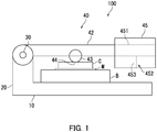
- FIG. 1 is a schematic side view of the bonding device 100 according to the embodiment of the present invention.
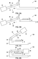
- FIGS. 2A to 2D are schematic side views of the bonding device 100 according to the embodiment of the present invention for illustrating a bonding method thereof.
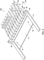
- FIG. 3 is a perspective view of the bonding device 100 according to the embodiment of the present invention.
- the bonding device 100 includes a frame 10, a wall section 20, a rotational shaft 30, and a plurality of pressing sections 40.
- the bonding device 100 bonds components C to a substrate B using a metal material M.
- the metal material M contains particles of a metal dispersed therein, such as silver, copper, or nickel.
- the metal material M is a paste prepared by mixing the metal particles and a solvent such as alcohol.
- the substrate B is for example a lead frame.
- the components C are for example semiconductor chips.
- the components C may for example be wires.
- the frame 10 supports the wall section 20.
- the frame 10 is for example made from stainless steel.
- a support base 14 ( FIG. 3 ) is attached to the frame 10.
- the support base 14 is to support the substrate B.
- the support base 14 is for example made from copper.
- the wall section 20 extends in a vertical direction.
- the wall section 20 is for example made from stainless steel.
- the rotational shaft 30 is fixed to the wall section 20.
- the rotational shaft 30 extends in a longitudinal direction.
- the rotational shaft 30 is for example made from stainless steel.
- Each of the pressing sections 40 has an arm 42, a presser 43, and a weight 45.
- the arms 42 extend from the rotational shaft 30.
- the arms 42 are for example made from stainless steel.
- the arms 42 pivot about the rotational shaft 30.
- the pressers 43 for example have a spherical shape.
- the pressers 43 for example have a diameter of 5 mm.
- the pressers 43 are attached to the respective arms 42. Specifically, half of each presser 43 is embedded in the corresponding arm 42, and the other half thereof is exposed from the arm 42.
- the pressers 43 press the components C.
- Each presser 43 has a pressing surface 44.
- each of the pressing surfaces 44 is downwardly convex. More preferably, each of the pressing surfaces 44 is a portion of a spherical surface.
- the components C are bonded to the substrate B through point contact of the pressers 43 with the respective components C.
- the components C are bonded to the substrate B through point contact of each presser 43 with a central region of the corresponding component C.
- the pressers 43 are elastic bodies.
- the pressers 43 are for example made from TEFLON (registered Japanese trademark). Since the pressers 43 are elastic bodies, it is possible to prevent the pressers 43 from damaging the components C when the pressers 43 press the components C.
- the weights 45 are attached to the respective arms 42.
- the weights 45 are for example made from copper.
- the weights 45 for example have a rectangular prism shape.
- Each of the weights 45 has a through hole 451 and a screw hole 452.
- a diameter of the through holes 451 is substantially the same as a diameter of the arms 42.
- Each of the weights 45 is attached to a specific location in the corresponding arm 42 through the arm 42 being inserted into the through hole 451 and a screw 453 being inserted into the screw hole 452.
- the weights 45 have a size determined so as to prevent the pressers 43 from making contact with another element (for example, the frame 10) when the pressers 43 are in point contact with the respective components C.
- the pressers 43 are located between the rotational shaft 30 and the weights 45.
- the principle of leverage works using the rotational shaft 30 as point of fulcrum, the weights 45 as point of effort, and the pressers 43 as point of load.
- the bonding device 100 can achieve high pressure while saving space.
- Addition of a mechanism for changing positions of the pressers 43 further makes it possible to adjust the load on the pressers 43 by changing a distance between the pressers 43 and the rotational shaft 30.
- the following describes a bonding method that is implemented by the bonding device 100 with reference to FIGS. 2A to 2D .
- the substrate B and the components C are bonded together using the metal material M through processes illustrated in FIGS. 2A to 2D .
- the bonding device 100 is prepared as illustrated in FIG. 2A .
- the pressing surfaces 44 are oriented upward when the bonding device 100 is in a state illustrated in FIG. 2A .
- the substrate B is placed on an upper surface of the support base 14 ( FIG. 3 ) as illustrated in FIG. 2B .
- the metal material M is applied onto an upper surface of the substrate B.
- the components C are placed on the metal material M. That is, a layer of the components C is formed on the substrate B with the metal material M therebetween.
- the arms 42 are pivoted clockwise as illustrated in FIG. 2C .
- the arms 42 are pivoted clockwise until the pressers 43 come in point contact with the respective components C as illustrated in FIG. 2D .
- the bonding device 100 bonds the components C to the substrate B through point contact of the pressers 43 with the respective components C.
- the bonding device 100 is placed in a heating oven and the metal material M is sintered to bond the components C to the substrate B.
- a generic device pressure is applied to the components C by placing a component pressing plate such as a glass board on the components C and stacking up weights on the component pressing plate.
- a component pressing plate such as a glass board
- the bonding device 100 uses the principle of leverage, and thus the bonding device 100 can have a lower height. Accordingly, the heating oven that receives the bonding device 100 can have a lower height. As a result, it is possible to efficiently heat and sinter the metal material M.
- the support base 14 has a higher thermal conductivity than the arms 42. Accordingly, during the sintering of the metal material M, the support base 14 easily conducts heat from below to the substrate B and the components C, and the arms 42 prevent the heat from easily escaping upward from the substrate B and the components C. As a result, it is possible to efficiently heat the metal material M.
- An extending direction of the arms 42 is parallel to a horizontal direction when the pressers 43 are in point contact with the respective components C. Accordingly, the bonding device 100 can have a lower height. As a result, the heating oven that receives the bonding device 100 can have a lower height. It is therefore possible to efficiently heat and sinter the metal material M.
- FIG. 4 is a perspective view illustrating the substrate B and the components C.
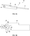
- FIG. 5A is a perspective view of one of the pressing sections 40 according to the embodiment of the present invention.
- FIG. 5B is a side view illustrating a rotational shaft holding section 46.
- FIG. 6A is a side view illustrating the rotational shaft 30.
- FIG. 6B is a cross-sectional view illustrating an arm attachment section 32.
- FIG. 7 is a perspective view illustrating a portion of the rotational shaft 30 in the vicinity of the wall section 20.
- FIGS. 8A and 8B are cross-sectional views illustrating the arm attachment section 32 and the rotational shaft holding section 46.
- the bonding device 100 includes ten pressing sections 40. Each of the ten pressing sections 40 presses a corresponding one of the components C. Thus, the bonding device 100 can apply pressure to each of the components C separately. As such, the bonding device 100 can set a separate pressure for each of the components C.
- each of the arms 42 has the rotational shaft holding section 46 and a weight attachment section 47.
- the rotational shaft holding section 46 holds the rotational shaft 30.
- Each of the weights 45 is attached to the corresponding weight attachment section 47.
- the support base 14 is a plate-shaped member.
- the support base 14 has a rectangular shape.
- the support base 14 is attachable to and detachable from the frame 10.
- the support base 14 has a pair of positioning pins 16. The pair of positioning pins 16 can fix a position of the substrate B placed on the support base 14.
- the substrate B includes unit substrates Ba arranged in parallel into the shape of a strip.
- the substrate B according to the present embodiment has ten unit substrates Ba.
- Each of the unit substrates Ba receives placement of one component C.
- the substrate B has a plurality of guide holes H.
- the number of guide holes H is not limited as long as the substrate B has at least one pair of guide holes H.
- the positioning pins 16 ( FIG. 3 ) are respectively inserted into guide holes Ha and Hb in a pair, so that the substrate B is fixed to a specific position.
- the bonding device 100 includes the pressing sections 40.
- the bonding device 100 can apply pressure to each of the components C separately. It is therefore possible to prevent variation in applied pressure among the components C.
- a thickness d1 indicates a thickness of the rotational shaft holding section 46.
- each pressing section 40 has the arm 42 and the presser 43.
- the arm 42 has the rotational shaft holding section 46 and the weight attachment section 47.
- the rotational shaft holding section 46 is plate-shaped.
- the thickness d1 of the rotational shaft holding section 46 is for example 6 mm.
- One end of the rotational shaft holding section 46 is connected with the weight attachment section 47.
- the other end of the rotational shaft holding section 46 has a C-shaped cutout 48.
- the presser 43 is attached to the rotational shaft holding section 46.
- the weight attachment section 47 is rod-shaped.
- the weight attachment section 47 is cylindrical.
- the weight 45 is attached to the weight attachment section 47.
- a center c1 indicates a center of a circle defining an arc-shaped section 492.
- a radius r1 indicates a radius of the circle defining the arc-shaped section 492.
- a distance d6 indicates a distance between a first flat section 494 and a second flat section 496.
- a diameter d7 indicates a diameter of the circle defining the arc-shaped section 492.
- a length d8 indicates a length of the first flat section 494.
- a length d9 indicates a length of the second flat section 496.
- the rotational shaft holding section 46 has the arc-shaped section 492, the first flat section 494, and the second flat section 496.
- the arc-shaped section 492, the first flat section 494, and the second flat section 496 define the cutout 48.
- the arc-shaped section 492 has an arc shape.
- the arc-shaped section 492 is a portion of the circle having the center c1 and the radius r1.
- the radius r1 is for example 5 mm.
- the first flat section 494 is connected with one end 493 of the arc-shaped section 492.
- the first flat section 494 is flat.
- the second flat section 496 is connected with another other end 495 of the arc-shaped section 492.
- the second flat section 496 is flat.
- the distance d6 is shorter than the diameter d7.
- the distance d6 is for example 9 mm.
- the diameter d7 is for example 10 mm.
- the length d8 of the first flat section 494 is longer than the length d9 of the second flat section 496.
- a distance d11 indicates a distance between a pair of arm movement restriction sections 70.
- a center c2 indicates a center of a circle defining an arc-shaped section 322.
- a radius r2 indicates a radius of the circle defining the arc-shaped section 322.
- a shortest distance d16 indicates a shortest distance from the center c2 to a flat section 324.
- a length d17 indicates a length obtained as a sum of the radius r2 and the shortest distance d16.
- a diameter d18 indicates a diameter of the circle defining the arc-shaped section 322.
- the rotational shaft 30 has a plurality of arm attachment sections 32, a plurality of main body sections 34, and a plurality of arm movement restriction sections 70.
- Each of the arm attachment sections 32 has a cylindrical shape having a cutaway portion.
- the arms 42 are attached to the respective arm attachment sections 32.
- Each of the main body sections 34 is cylindrical.
- the main body sections 34 are connected with the arm attachment sections 32 via the arm movement restriction sections 70.
- each of the arm movement restriction sections 70 has an annular section 72, a protruding section 74, and a cutout 76.
- the annular section 72 is ring-shaped.
- the protruding section 74 protrudes from the annular section 72.
- the annular section 72 has the cutout 76.
- Each pair of adjacent arm movement restriction sections 70 restricts movement of a corresponding one of the arms 42 in an axial direction D1 of the rotational shaft 30.
- Each of the arm attachment sections 32 is defined by one of pairs of arm movement restriction sections 70. That is, the pairs of arm movement restriction sections 70 are provided in one-to-one correspondence with the arms 42.
- the distance d11 ( FIG. 6A ) between each pair of arm movement restriction sections 70 is substantially equal to the thickness d1 ( FIG. 5A ) of each rotational shaft holding section 46.
- each arm attachment section 32 has the arc-shaped section 322 and the flat section 324.
- the arc-shaped section 322 has an arc shape.
- the arc-shaped section 322 is a portion of the circle having the center c2 and the radius r2.
- the radius r2 is for example 5 mm. According to the present embodiment, the radius r2 is equal to the radius r1 ( FIG. 5B ).
- the flat section 324 is connected with the arc-shaped section 322.
- the flat section 324 is flat.
- the length d17 is equal to or shorter than the distance d6 ( FIG. 5B ). According to the present embodiment, the length d17 is equal to the distance d6.
- the length d17 is for example 9 mm.
- the radius r2 is for example 5 mm.
- the shortest distance d16 is for example 4 mm.
- the diameter d18 is greater than the distance d6 ( FIG. 5B ).
- the arms 42 are attachable to and detachable from the rotational shaft 30.
- the following describes a configuration in which the arms 42 are attachable and detachable with reference to FIGS. 5A to 6B , 8A, and 8B .
- the diameter d18 is greater than the distance d6.
- the length d17 is equal to or shorter than the distance d6.
- the length d17 is substantially equal to the distance d6.
- Each rotational shaft holding section 46 can therefore be attached to the corresponding arm attachment section 32 when the rotational shaft holding section 46 is angled in a direction D2 where the first flat section 494 and the second flat section 496 of the rotational shaft holding section 46 are parallel to the flat section 324 of the arm attachment section 32 as illustrated in FIG. 8A .
- the rotational shaft holding section 46 angled in the direction D2 allows the arm attachment section 32 to pass between the first flat section 494 and the second flat section 496.
- the rotational shaft holding section 46 can be attached to the arm attachment section 32. That is, the arm 42 can be attached to the rotational shaft 30.
- the rotational shaft holding section 46 is kept on the arm attachment section 32 through the rotational shaft holding section 46 being pivoted and angled in any direction other than the direction D2 as illustrated in FIG. 8B . Since the diameter d18 is greater than the distance d6, the second flat section 496 gets caught on the arm attachment section 32 to prevent the rotational shaft holding section 46 from coming off the arm attachment section 32. According to the present embodiment, the radius r1 is equal to the radius r2. Accordingly, the rotational shaft holding section 46 can be smoothly pivoted with the arc-shaped section 492 of the rotational shaft holding section 46 sliding along the arc-shaped section 322 of the arm attachment section 32.
- the rotational shaft holding section 46 kept on the arm attachment section 32 as illustrated in FIG. 8B becomes able to allow the arm attachment section 32 to pass between the first flat section 494 and the second flat section 496 by being angled in the direction D2 so as to shift to a state illustrated in FIG. 8A .
- the rotational shaft holding section 46 can be detached from the arm attachment section 32. That is, the arm 42 can be detached from the rotational shaft 30.
- the arms 42 are attachable to and detachable from the rotational shaft 30. It is therefore possible to bond only desired components C by selecting such components and detaching corresponding arms 42 from the rotational shaft 30.
- the diameter d18 of the circle defining the arc-shaped section 322 of the arm attachment section 32 is greater than the distance d6 between the first flat section 494 of the rotational shaft holding section 46 and the second flat section 496 of the rotational shaft holding section 46. Furthermore, the length d17 obtained as a sum of the radius r2 of the circle defining the arc-shaped section 322 of the arm attachment section 32 and the shortest distance d16 from the center c2 of the circle defining the arc-shaped section 322 of the arm attachment section 32 to the flat section 324 of the arm attachment section 32 is equal to or shorter than the distance d6 between the first flat section 494 of the rotational shaft holding section 46 and the second flat section 496 of the rotational shaft holding section 46.
- the rotational shaft holding section 46 can be attached to and detached from the arm attachment section 32 only when the rotational shaft holding section 46 is at a specific angle.
- the rotational shaft holding section 46 is kept on the arm attachment section 32 when the rotational shaft holding section 46 is at any angle other than the specific angle.
- the bonding device 100 bonds the components C to the substrate B using the metal material M through point contact of the pressers 43 with the respective components C. It is therefore possible to apply uniform pressure to the entire area of each component C. This results in highly reproducible bonding with less shear strength variation among the components C on the substrate B.
- each of the pressing surfaces 44 in the bonding device 100 is downwardly convex. Accordingly, the pressers 43 can come in point contact with the respective components C. As a result, it is possible to apply uniform pressure to the entire area of each component C.
- the bonding device 100 bonds the components C to the substrate B through point contact of each presser 43 with the central region of the corresponding component C. It is therefore possible to apply uniform pressure to the entire area of each component C.
- the bonding device 100 includes at least one pressing section 40, and each pressing section 40 has the arm 42 and the weight 45 attached to the arm 42 as described with reference to FIGS. 1 to 8B .
- Each pressing section 40 also has the presser 43 located between the rotational shaft 30 and the weight 45.
- the principle of leverage works using the rotational shaft 30 as point of fulcrum, the weight 45 as point of effort, and the presser 43 as point of load.
- the bonding device 100 can achieve high pressure while saving space.
- Addition of a mechanism for changing the position of the presser 43 further makes it possible to adjust the load on the presser 43 by changing the distance between the presser 43 and the rotational shaft 30.
- the arms 42 are attachable to and detachable from the rotational shaft 30. It is therefore possible to bond only desired components C by selecting such components and detaching corresponding arms 42 from the rotational shaft 30.
- the bonding device 100 includes the support base 14 that supports the substrate B.
- the support base 14 also fixes the position of the substrate B.
- the position of the substrate B can be fixed so that each of the pressers 43 comes in point contact with the central region of the corresponding component C. It is therefore possible to apply uniform pressure to the entire area of each component C.
- the support base 14 has a higher thermal conductivity than the arms 42. Accordingly, during the sintering of the metal material M, the support base 14 easily conducts heat from below to the substrate B and the components C, and the arms 42 prevent the heat from easily escaping upward from the substrate B and the components C. As a result, it is possible to efficiently heat the metal material M. In a configuration in which the pressers 43 are made from a heat-resistant and low-thermal-conductive fluororesin, the pressers 43 also prevents the heat from easily escaping even when the pressers 43 are in direct contact with the respective components C, enabling more efficient heating.
- the extending direction of the arms 42 is parallel to the horizontal direction when the pressers 43 are in point contact with the respective components C. Accordingly, the bonding device 100 can have a lower height. As a result, the heating oven that receives the bonding device 100 can have a lower height. It is therefore possible to efficiently heat and sinter the metal material M.
- the pressers 43 are elastic bodies. It is therefore possible to prevent the pressers 43 from damaging the components C when the pressers 43 press the components C.
- the bonding device 100 includes a plurality of pressing sections 40. Each of the pressing sections 40 presses a corresponding one of the components C. Thus, the bonding device 100 can apply pressure to each of the components C separately. As such, the bonding device 100 can set a separate pressure for each of the components C.
- FIG. 9A is a diagram illustrating the substrate B and the components C bonded together by the bonding device 100 according to the embodiment of the present invention.
- FIG. 9B is a graph illustrating a result of shear strength of the substrate B and the components C bonded together by a conventional method.
- FIG. 9C is a graph illustrating a result of shear strength of the components C bonded by the bonding device 100 according to the embodiment of the present invention.
- the horizontal axis represents number of the components C
- the vertical axis represents shear strength.
- the bonding device 100 illustrated in FIG. 3 in which the weight of the weights 45 had been adjusted was used.
- Ten 1.85 mm ⁇ 1.85 mm square SiC Schottky barrier diodes (components C) were bonded to a TO247 lead frame (substrate B) as illustrated in FIG. 9A .
- the bonding device 100 was placed in a vacuum oven (RSS-450-210), product of UniTemp.
- a chip-to-chip pitch was 17.5 mm, and ten arms 42 were arranged according to the pitch.
- a silver paste was used as a die attach material (metal material M).
- the weights 45 were fixed to the respective arms 42 so as to apply a load of 140 g (0.4 MPa) to a center of each chip during sintering.
- the TO247 frame was positioned and fixed by inserting thereto two positioning pins 16 provided on the support base 14.
- the conventional bonding method resulted in shear strength variation among the components C. This is thought to be because the conventional bonding method is not capable of applying uniform pressure to each component due to pressurization through face contact of one component pressing plate with the components C.
- bonding of the components C by the bonding device 100 according to the embodiment of the present invention resulted in a shear strength variation of 1/5. This is thought to be because the bonding device 100 is capable of applying uniform pressure to each component C through point contact and component-by-component pressurization. Cross-section observation was performed to confirm that the sintered die attach material had a uniform thickness. The observation result proved that the load applied during the pressurization was uniform.
- FIG. 10 is a perspective view of the bonding device 100 according to another embodiment of the present invention.
- Each arm 42 has two pressers 43.
- the two pressers 43 respectively come in point contact with different components C. It is therefore possible to apply pressure to components C in various arrangements on the substrate B.
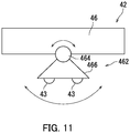
- FIG. 11 is a schematic side view of such an arm 42. As illustrated in FIG. 11 , the arm 42 further has a presser holding section 462.
- the presser holding section 462 has a movable section 464 and a presser attachment section 466.
- the movable section 464 is attached to the rotational shaft holding section 46.
- the movable section 464 is movable from front to back and from side to side about a fixed point on the rotational shaft holding section 46.
- the presser attachment section 466 is attached to the movable section 464.
- the two pressers 43 are attached to the presser attachment section 466.
- the presser attachment section 466 moves with movement of the movable section 464. It is therefore possible to apply uniform pressure to a plurality of components C through a plurality of pressers 43 provided on one arm 42.
- each arm 42 has a plurality of pressers 43 for respectively applying pressure to a plurality of components C
- the number of pressers 43 is preferably no greater than three in terms of applying uniform pressure to the plurality of components C.
- the three pressers 43 are preferably disposed on respective vertices of an equilateral triangle.
- FIG. 12 is a perspective view of the bonding device 100 according to another embodiment of the present invention.
- Each pressing section 40 has two arms 42 and two pressers 43.
- the arms 42 of each pressing section 40 are partially coupled.
- the two pressers 43 can be simultaneously brought into point contact with components C by pivoting the arms 42.
- the pressers 43 according to such a configuration are flexibly movable as described with reference to FIG. 11 . As a result, it is possible to apply uniform pressure to the components C.
- positions of the pressers 43 are changed according to positions of the components C placed on the substrate B.
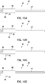
- the following describes the reason why the positions of the pressers 43 are preferably changed according to the positions of the components C placed on the substrate B with reference to FIGS. 13A to 13D.
- FIGS. 13A to 13D are schematic side views of one pressing section 40 according to the embodiment of the present invention.
- a position of the presser 43 illustrated in FIG. 13B is farther toward one end in the extending direction of the arm 42 (referred to below as an arm direction) than a position of the presser 43 illustrated in FIG. 13A . That is, even in a situation in which positions of the components C on the substrate B are changed in the arm direction, the components C can be bonded to the substrate B by changing the positions of the pressers 43 in the arm direction.
- a length of the presser 43 illustrated in FIG. 13C in a height direction is greater than a length of the presser 43 illustrated in FIG. 13A in the height direction.
- the pressing surface 44 of the presser 43 illustrated in FIG. 13C is located below the pressing surface 44 of the presser 43 illustrated in FIG. 13A . That is, even in a situation in which the substrate B having a different thickness is used or the components C having a different thickness are used, the components C can be bonded to the substrate B by changing the length of the pressers 43 in the height direction.
- a length of the rotational shaft holding section 46 illustrated in FIG. 13D in the height direction is greater than a length of the rotational shaft holding section 46 illustrated in FIG. 13A in the height direction. That is, even in a situation in which the substrate B having a smaller thickness is used or the components C having a smaller thickness are used, the components C can be bonded to the substrate B by changing the length of the rotational shaft holding sections 46 in the height direction.
- the bonding device 100 is capable of bonding a plurality of components C aligned in the arm direction to the substrate B.
- the following describes the bonding device 100 according to another embodiment of the present invention with reference to FIGS. 14A and 14B.
- FIG. 14A is a schematic side view of the bonding device 100 according to the embodiment of the present invention.
- FIG. 14B is a schematic perspective view of the bonding device 100 according to the embodiment of the present invention. Description is omitted for elements of the bonding device 100 illustrated in FIGS. 14A and 14B that are the same as those of the bonding devices 100 described with reference to FIGS. 1 to 13D .
- the bonding device 100 illustrated in FIGS. 14A and 14B includes the frame 10, the wall section 20, a first rotational shaft 30a, a second rotational shaft 30b, a third rotational shaft 30c, a first pressing section 40a, a second pressing section 40b, and a third pressing section 40c.
- the frame 10 supports the wall section 20.
- the wall section 20 extends in the vertical direction.
- the first rotational shaft 30a, the second rotational shaft 30b, and the third rotational shaft 30c are fixed to the wall section 20. Positions of the first rotational shaft 30a, the second rotational shaft 30b, and the third rotational shaft 30c differ from one another in terms of the height direction. Positions of the first rotational shaft 30a, the second rotational shaft 30b, and the third rotational shaft 30c differ from one another also in terms of the arm direction.
- the first pressing section 40a extends from the first rotational shaft 30a.
- the second pressing section 40b extends from the second rotational shaft 30b.
- the third pressing section 40c extends from the third rotational shaft 30c.
- the first pressing section 40a has a first arm 42a, a first presser 43a, and a weight 45a.
- the second pressing section 40b has a second arm 42b, a second presser 43b, and a weight 45b.
- the third pressing section 40c has a third arm 42c, a third presser 43c, and a weight 45c. Lengths of the first presser 43a, the second presser 43b, and the third presser 43c in the height direction differ from one another. Specifically, the first presser 43a is the longest, the second presser 43b is the second longest, and the third presser 43c is the third longest in the height direction.
- the lengths of the first presser 43a, the second presser 43b, and the third presser 43c are determined so that a pressing surface 44a of the first presser 43a, a pressing surface 44b of the second presser 43b, and a pressing surface 44c of the third presser 43c come to the same position in terms of the height direction when the first arm 42a, the second arm 42b, and the third arm 42c are pivoted.
- the second arm 42b has an opening 49b.
- the opening 49b allows the first presser 43a to pass therethrough.
- the third arm 42c has an opening 49c.
- the opening 49c allows the first presser 43a and the second presser 43b to pass therethrough. Accordingly, the second arm 42b can be pivoted with the second presser 43b passing through the opening 49c after the third arm 42c has been pivoted.
- the first arm 42a can be pivoted with the first presser 43a passing through the opening 49b and the opening 49c after the second arm 42b has been pivoted.
- the pressing surface 44a of the first presser 43a, the pressing surface 44b of the second presser 43b, and the pressing surface 44c of the third presser 43c come to the same position in terms of the height direction as a result of the first arm 42a, the second arm 42b, and the third arm 42c being pivoted.
- the pressing surface 44a of the first presser 43a, the pressing surface 44b of the second presser 43b, and the pressing surface 44c of the third presser 43c are aligned in the arm direction. It is therefore possible to bond a plurality of components C aligned in the arm direction to the substrate B.
- weight 45a, the weight 45b, and the weight 45c are attached to respective locations that prevent the weight 45a, the weight 45b, and the weight 45c from interfering with one another when the first arm 42a, the second arm 42b, and the third arm 42c are pivoted.
- a plurality of first pressing sections 40a, a plurality of second pressing sections 40b, and a plurality of third pressing sections 40c may be provided and aligned in an extending direction of the first rotational shaft 30a, an extending direction of the second rotational shaft 30b, and an extending direction of the third rotational shaft 30c, respectively.
- Such a configuration enables bonding of components C arranged in a matrix on the substrate B.
- a configuration having three first pressing sections 40a, three second pressing sections 40b, and three third pressing sections 40c enables bonding of components C arranged on the substrate B in a 3-by-3 matrix (nine components C in total) to the substrate B.
- the second arm 42b of the second pressing section 40b has the opening 49b that allows the first presser 43a of the first pressing section 40a to pass therethrough.
- the first presser 43a can therefore pass through the opening 49b when the first arm 42a is pivoted.
- the bonding device 100 can bond a plurality of components C aligned in the arm direction to the substrate B.
- the bonding devices 100 described with reference to FIGS. 1 to 14B bond the components C to the substrate B by pivoting the arms 42 to bring the pressers 43 attached to the pressing sections 40 into contact with the components C.
- the arms 42 and the pressers 43 may be separate, and the bonding device 100 may bond the components C to the substrate B by pivoting the arms 42 to bring the pressers 43 into contact with the arms 42.
- FIG. 15 is a schematic perspective view of the bonding device 100 according to the embodiment of the present invention.
- FIG. 16A is a schematic side view of the bonding device 100 according to the embodiment of the present invention.
- FIG. 16B is a schematic enlarged view of a contact section 50 and elements therearound. In FIG.
- a contact point P1 is a point of contact between a first end movable section 54a and the presser 43a
- a contact point P2 is a point of contact between the first end movable section 54a and the presser 43b
- a contact point P3 is a point of contact between a second end movable section 54b and the presser 43b
- a contact point P4 is a point of contact between the second end movable section 54b and the presser 43c. Description is omitted for elements of the bonding device 100 illustrated in FIGS. 15 to 16B that are the same as those of the bonding devices 100 described with reference to FIGS. 1 to 14B .
- the bonding device 100 illustrated in FIGS. 15 and 16A includes the frame 10, the wall section 20, the rotational shaft 30, the first pressing section 40a, the second pressing section 40b, the third pressing section 40c, the support base 14, and a plate-shaped member 18.
- Each of the arm 42 of the first pressing section 40a, the arm 42 of the second pressing section 40b, and the arm 42 of the third pressing section 40c has the contact section 50.
- Each of the first pressing section 40a, the second pressing section 40b, and the third pressing section 40c has three pressers 43. As illustrated in FIG. 16B , the pressers 43 are disposed in the plate-shaped member 18.
- the contact section 50 includes a connection movable section 52, the first end movable section 54a, and the second end movable section 54b.
- the connection movable section 52 is attached to the rotational shaft holding section 46.
- the connection movable section 52 has a shaft 522.
- the connection movable section 52 is movable about the shaft 522.
- the first end movable section 54a has a shaft 542a (fixed point).
- the first end movable section 54a is movable about the shaft 542a.
- the second end movable section 54b has a shaft 542b (fixed point).
- the second end movable section 54b is movable about the shaft 542b.
- the contact section 50 comes in contact with the pressers 43.
- the first end movable section 54a and the second end movable section 54b come in contact with the pressers 43.
- the bonding device 100 bonds the components C to the substrate B by bringing the movable sections 54a and 54b into point contact with the pressers 43, and thus bringing the pressers 43 into contact with the components C.
- one end of the first end movable section 54a comes in point contact with the presser 43a at the contact point P1.
- the other end of the first end movable section 54a comes in point contact with the presser 43b at the contact point P2.
- One end of the second end movable section 54b comes in point contact with the presser 43c at the contact point P4.
- the other end of the second end movable section 54b comes in point contact with the presser 43b at the contact point P3.
- the bonding device 100 can bond a plurality of components C aligned in the arm direction to the substrate B.
- the three pressing sections 40 are aligned in the axial direction of the rotational shaft 30, and it is therefore possible to bond the components C arranged in a matrix on the substrate B.
- Each of the presser 43a, the presser 43b, and the presser 43c has a large-diameter section 412 and a small-diameter section 414.
- the large-diameter section 412 has a larger diameter than the small-diameter section 414.
- the large-diameter section 412 and the small-diameter section 414 are for example cylindrical.
- the small-diameter section 414 has a greater height than the large-diameter section 412.
- the pressing surfaces 44 are flat.
- the pressing surfaces 44 may have a shape of a portion of a spherical surface.
- the plate-shaped member 18 is attached to the frame 10.
- the plate-shaped member 18 is located above the support base 14.
- the plate-shaped member 18 has through holes 182.
- the through holes 182 have a larger diameter than the small-diameter sections 414.
- the small-diameter sections 414 can therefore pass through the respective through holes 182.
- the through holes 182 have a smaller diameter than the large-diameter sections 412.
- An elastic member 60a, an elastic member 60b, and an elastic member 60c are for example springs.
- the elastic member 60a is attached to the presser 43a.
- the elastic member 60b is attached to the presser 43b.
- the elastic member 60c is attached to the presser 43c.
- the elastic member 60a surrounds a portion of the small-diameter section 414 with one end thereof attached to the large-diameter section 412.
- the elastic member 60a, the elastic member 60b, and the elastic member 60c have a larger diameter than the small-diameter sections 414.
- the elastic member 60a, the elastic member 60b, and the elastic member 60c have a larger diameter than the through holes 182.
- the elastic member 60a, the elastic member 60b, and the elastic member 60c cannot pass through the respective through holes 182.
- the elastic members 60 push up the respective pressers 43 when the pressers 43 are out of contact with the contact section 50 as a result of the arms 42 being pivoted, which in other words is when no load is applied from the contact section 50 to the pressers 43.
- Such a configuration allows the substrate B and the components C to be easily placed on the support base 14.
- the bonding device 100 described above with reference to FIGS. 15 to 16B bonds the components C to the substrate B through point contact of the pressers 43 with the movable sections 54a and 54b. It is therefore possible to apply uniform pressure to a plurality of components C using a plurality of pressers 43 provided on one arm 42.
- the contact section 50 has a plurality of movable sections (the connection movable section 52, the first end movable section 54a, and the second end movable section 54b).
- the present invention is not limited as such so long as the movable section can be brought into contact with the pressers 43.
- the contact section 50 may have only one movable section.
- the bonding device 100 has a configuration in which points of pressurization on the components C by the pressing sections 40 are changeable.
- FIG. 17A is a schematic top view of the bonding device 100 according to another embodiment of the present invention.
- FIG. 17B is a schematic side view of the bonding device 100 according to the embodiment of the present invention.
- the axial direction D1 indicates the axial direction of the rotational shaft 30.
- the direction D2 indicates the arm direction.
- a direction D3 indicates the vertical direction.
- the bonding device 100 includes a position adjustment mechanism that enables the pressing sections 40 to move in the axial direction D1 as illustrated in FIG. 17A .
- the bonding device 100 also includes a position adjustment mechanism that enables the pressing sections 40 to move in the direction D2.
- Such a configuration enables points of pressurization on the components C by the pressing sections 40 to be changeable. As a result, the components C can be placed on the substrate B more flexibly.
- the bonding device 100 includes a position adjustment mechanism that enables the pressing sections 40 to move in the direction D3 as illustrated in FIG. 17B .
- a position adjustment mechanism that enables the pressing sections 40 to move in the direction D3 as illustrated in FIG. 17B .
- Such a configuration enables bonding of the components C to the substrate B without changing the shape of the support base 14 even in a situation in which the substrate B having a different height is used or the components C having a different height are used.
- FIG. 18 is a schematic side view of one pressing section 40 according to another embodiment of the present invention.
- a contact point P11 is a point of contact between the arm 42 and the presser 43. Description is omitted for elements of the bonding device 100 illustrated in FIG. 18 that are the same as those of the bonding devices 100 described with reference to FIGS. 1 to 17B .
- the presser 43 illustrated in FIG. 18 is not attached to the arm 42. That is, the arm 42 and the presser 43 are separable.
- the pressers 43 according to the present embodiment are rigid.
- the pressing surfaces 44 are flat.
- the pressers 43 are placed above the substrate B.
- Each of the pressers 43 is brought into point contact with the corresponding arm 42 at the contact point P11 by pivoting the arm 42.
- the surfaces that come in point contact are upwardly convex.
- the pressers 43 according to the present embodiment are rigid. It is therefore possible to bond less rigid components C such as thin-film chips to the substrate B.
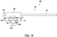
- FIG. 19 is a schematic side view of one pressing section 40 according to another embodiment of the present invention.
- a contact point P21 is a point of contact between a substrate supporting member 90 and a reference surface 142. Description is omitted for elements of the bonding device 100 illustrated in FIG. 19 that are the same as those of the bonding devices 100 described with reference to FIGS. 1 to 18 .
- the pressing section 40 illustrated in FIG. 19 has the arm 42 and the substrate supporting member 90.
- the substrate supporting member 90 supports the substrate B.
- the substrate supporting member 90 has a flat section 92 and a semispherical section 94.
- the flat section 92 is flat.
- the semispherical section 94 is semispherical.
- the support base 14 has the reference surface 142.
- the reference surface 142 has a recessed section 144.
- the substrate supporting member 90 is disposed on the reference surface 142. Specifically, a portion of the semispherical section 94 is disposed in the recessed section 144.
- the substrate supporting member 90 is movably supported by the recessed section 144.
- the recessed section 144 has suction holes.
- the substrate supporting member 90 can be fixed by being sucked on through the suction holes by a suction mechanism.
- the substrate B and the components C are placed on the substrate supporting member 90. Subsequently, the arms 42 are pivoted to press the components C. The substrate supporting member 90 then becomes stable in a position where uniform load is applied to the entire area of each component C. The substrate supporting member 90 in this state is in point contact with the reference surface 142 at the contact point P21. Once the substrate supporting member 90 is stable in the position, the substrate supporting member 90 is sucked on through the suction holes by the suction mechanism to be fixed.
- the bonding device 100 described with reference to FIG. 19 bonds the components C to the substrate B through point contact between the substrate supporting member 90 and the reference surface 142. It is therefore possible to apply uniform pressure to the entire area of each component C.
- FIGS. 1 to 19 the present invention is not limited to the above embodiments and may be implemented in various different forms that do not deviate from the essence of the present invention (for example, as described below in (1) and (2)).
- the drawings schematically illustrate elements of configuration in order to facilitate understanding and properties of elements of configuration illustrated in the drawings, such as thickness, length, and number thereof, may differ from actual properties thereof in order to facilitate preparation of the drawings.
- properties of elements of configuration described in the above embodiments, such as materials, shapes, and dimensions are merely examples and are not intended as specific limitations. Various alterations may be made so long as there is no substantial deviation from the effects of the present invention.
Landscapes
- Engineering & Computer Science (AREA)
- Mechanical Engineering (AREA)
- Die Bonding (AREA)
- Electric Connection Of Electric Components To Printed Circuits (AREA)
- Pressure Welding/Diffusion-Bonding (AREA)
Abstract
Description
- The present invention relates to a bonding device.
-
Patent Literature 1 discloses a method for bonding members together using a paste. The paste includes a dispersion medium, and metal nanoparticles (metal material) are dispersed in the dispersion medium. The bonding method disclosed inPatent Literature 1 can make a bonding layer as thick as necessary by employing spacers. The bonding method enables pressurization at high pressure, and thus increases bonding strength to be obtained after sintering. - [Patent Literature 1]
Japanese Patent Application Laid-Open Publication No.2011-71301 - However, a bonding device disclosed in
Patent Literature 1 may allow a pressing plate thereof to warp due to face contact between the pressing plate and the members being pressed. It has therefore been difficult to apply uniform pressure to the entire area of each member. - The present invention has been made in view of the problems described above, and an object thereof is to provide a bonding device capable of applying uniform pressure to the entire area of a component.
- A bonding device according to the present invention bonds at least one component to a substrate using a metal material. The bonding device includes a wall section, at least one pressing section, and a rotational shaft. The rotational shaft is fixed to the wall section. The at least one pressing section has an arm and a presser or a substrate supporting member. The arm extends from the rotational shaft. The arm pivots about the rotational shaft. The presser presses the at least one component. The substrate supporting member is disposed on a reference surface. The substrate supporting member supports the substrate. The bonding device bonds the at least one component to the substrate through point contact of the presser with the at least one component or point contact of the substrate supporting member with the reference surface.
- In an embodiment, the presser has a pressing surface that presses the at least one component. The pressing surface is downwardly convex.
- In an embodiment, the pressing surface is a portion of a spherical surface.
- In an embodiment, the bonding device bonds the at least one component to the substrate through point contact of the presser with a central region of the at least one component.
- In an embodiment, the at least one pressing section further has a weight attached to the arm. The presser is located between the rotational shaft and the weight.
- In an embodiment, the arm is attachable to and detachable from the rotational shaft.
- In an embodiment, the rotational shaft has an arm attachment section to which the arm is attached. The arm attachment section has a cylindrical shape having a cutaway portion. The arm is attached to the arm attachment section. A peripheral surface of the arm attachment section has an arc-shaped section and a flat section. The arc-shaped section has an arc shape. The flat section is connected with the arc-shaped section. The flat section is flat. The arm has a rotational shaft holding section. The rotational shaft holding section has an arc-shaped section, a first flat section, and a second flat section. The arc-shaped section of the rotational shaft holding section has an arc shape. The first flat section is connected with one end of the arc-shaped section of the rotational shaft holding section. The first flat section is flat. The second flat section is connected with another end of the arc-shaped section of the rotational shaft holding section. The second flat section is flat. A diameter of a circle defining the arc-shaped section of the arm attachment section is greater than a distance between the first flat section of the rotational shaft holding section and the second flat section of the rotational shaft holding section. A length obtained as a sum of a radius of the circle defining the arc-shaped section of the arm attachment section and a shortest distance from a center of the circle defining the arc-shaped section of the arm attachment section to the flat section of the arm attachment section is equal to or shorter than the distance between the first flat section of the rotational shaft holding section and the second flat section of the rotational shaft holding section.
- In an embodiment, the rotational shaft further has a pair of arm movement restriction sections. The pair of arm movement restriction sections restricts movement of the arm in an axial direction of the rotational shaft. The arm attachment section is defined by the pair of arm movement restriction sections.
- In an embodiment, the bonding device further includes a support base that supports the substrate. The support base fixes a position of the substrate. The support base has a higher thermal conductivity than the arm.
- In an embodiment, an extending direction of the arm is parallel to a horizontal direction when the presser is in point contact with the at least one component.
- In an embodiment, the presser is an elastic body.
- In an embodiment, the elastic body includes a fluororesin.
- In an embodiment, the at least one component is a plurality of components. The at least one pressing section is a plurality of pressing sections. Each of the pressing sections presses a corresponding one of the components.
- In an embodiment, the at least one pressing section is a first pressing section and a second pressing section. The arm of the second pressing section has an opening that allows the presser of the first pressing section to pass therethrough.
- In an embodiment, the arm further has a contact section that comes in contact with the presser. The contact section has a movable section. The movable section is movable about a fixed point. The bonding device bonds the at least one component to the substrate through point contact of the presser with the movable section.
- According to the present invention, it is possible to apply uniform pressure to the entire area of a component.
-
-
FIG. 1 is a schematic side view of a bonding device according to an embodiment of the present invention. -
FIGS. 2A to 2D are schematic side views of the bonding device according to the embodiment of the present invention for illustrating a bonding method thereof. -
FIG. 3 is a perspective view of the bonding device according to the embodiment of the present invention. -
FIG. 4 is a perspective view illustrating a substrate and components. -
FIG. 5A is a perspective view of a pressing section according to the embodiment of the present invention. -
FIG. 5B is a side view illustrating a rotational shaft holding section. -
FIG. 6A is a side view illustrating a rotational shaft. -
FIG. 6B is a cross-sectional view illustrating an arm attachment section. -
FIG. 7 is a perspective view illustrating a portion of the rotational shaft in the vicinity of a wall section. -
FIGS. 8A and 8B are cross-sectional views illustrating the arm attachment section and the rotational shaft holding section. -
FIG. 9A is a diagram illustrating the substrate and the components bonded together by the bonding device according to the embodiment of the present invention. -
FIG. 9B is a graph illustrating a result of shear strength of the substrate and the components bonded together by a conventional method. -
FIG. 9C is a graph illustrating a result of shear strength of the components bonded by the bonding device according to the embodiment of the present invention. -
FIG. 10 is a perspective view of a bonding device according to another embodiment of the present invention. -
FIG. 11 is a schematic side view of an arm. -
FIG. 12 is a perspective view of the bonding device according to another embodiment of the present invention. -
FIGS. 13A to 13D are schematic side views of a pressing section according to the embodiment of the present invention. -
FIG. 14A is a schematic side view of a bonding device according to another embodiment of the present invention. -
FIG. 14B is a schematic perspective view of the bonding device according to the embodiment of the present invention. -
FIG. 15 is a schematic perspective view of a bonding device according to another embodiment of the present invention. -
FIG. 16A is a schematic side view of the bonding device according to the embodiment of the present invention. -
FIG. 16B is a schematic enlarged view of a contact section and elements therearound. -
FIG. 17A is a schematic top view of a bonding device according to another embodiment of the present invention. -
FIG. 17B is a schematic side view of the bonding device according to the embodiment of the present invention. -
FIG. 18 is a schematic side view of a pressing section according to another embodiment of the present invention. -
FIG. 19 is a schematic side view of a pressing section according to another embodiment of the present invention. - The following describes embodiments of the present invention with reference to the drawings. Elements that are the same or equivalent are indicated in the drawings using the same reference signs and description thereof will not be repeated.
- The following describes a
bonding device 100 according to an embodiment of the present invention with reference toFIGS. 1 to 3 .FIG. 1 is a schematic side view of thebonding device 100 according to the embodiment of the present invention.FIGS. 2A to 2D are schematic side views of thebonding device 100 according to the embodiment of the present invention for illustrating a bonding method thereof.FIG. 3 is a perspective view of thebonding device 100 according to the embodiment of the present invention. - As illustrated in
FIG. 1 , thebonding device 100 includes aframe 10, awall section 20, arotational shaft 30, and a plurality ofpressing sections 40. Thebonding device 100 bonds components C to a substrate B using a metal material M. - The metal material M contains particles of a metal dispersed therein, such as silver, copper, or nickel. The metal material M is a paste prepared by mixing the metal particles and a solvent such as alcohol.
- The substrate B is for example a lead frame.
- The components C are for example semiconductor chips. The components C may for example be wires.
- The
frame 10 supports thewall section 20. Theframe 10 is for example made from stainless steel. A support base 14 (FIG. 3 ) is attached to theframe 10. - As illustrated in
FIG. 3 , thesupport base 14 is to support the substrate B. Thesupport base 14 is for example made from copper. - Referring again to
FIG. 1 , thewall section 20 extends in a vertical direction. Thewall section 20 is for example made from stainless steel. - The
rotational shaft 30 is fixed to thewall section 20. Therotational shaft 30 extends in a longitudinal direction. Therotational shaft 30 is for example made from stainless steel. - Each of the
pressing sections 40 has anarm 42, apresser 43, and aweight 45. - The
arms 42 extend from therotational shaft 30. Thearms 42 are for example made from stainless steel. Thearms 42 pivot about therotational shaft 30. - The
pressers 43 for example have a spherical shape. Thepressers 43 for example have a diameter of 5 mm. Thepressers 43 are attached to therespective arms 42. Specifically, half of eachpresser 43 is embedded in thecorresponding arm 42, and the other half thereof is exposed from thearm 42. Thepressers 43 press the components C. Eachpresser 43 has apressing surface 44. Preferably, each of thepressing surfaces 44 is downwardly convex. More preferably, each of thepressing surfaces 44 is a portion of a spherical surface. - The components C are bonded to the substrate B through point contact of the
pressers 43 with the respective components C. Preferably, the components C are bonded to the substrate B through point contact of eachpresser 43 with a central region of the corresponding component C. As a result of eachpresser 43 coming in point contact with the central region of the corresponding component C, it is possible to prevent the components C from tilting, and thus apply uniform pressure to the entire area of each component C during bonding. Thepressers 43 are elastic bodies. Thepressers 43 are for example made from TEFLON (registered Japanese trademark). Since thepressers 43 are elastic bodies, it is possible to prevent thepressers 43 from damaging the components C when thepressers 43 press the components C. - The
weights 45 are attached to therespective arms 42. Theweights 45 are for example made from copper. Theweights 45 for example have a rectangular prism shape. Each of theweights 45 has a throughhole 451 and ascrew hole 452. A diameter of the throughholes 451 is substantially the same as a diameter of thearms 42. Each of theweights 45 is attached to a specific location in thecorresponding arm 42 through thearm 42 being inserted into the throughhole 451 and ascrew 453 being inserted into thescrew hole 452. Theweights 45 have a size determined so as to prevent thepressers 43 from making contact with another element (for example, the frame 10) when thepressers 43 are in point contact with the respective components C. Since only thepressers 43 come in point contact with the components C, it is possible to effectively apply pressure to the components C. Thepressers 43 are located between therotational shaft 30 and theweights 45. In thebonding device 100, the principle of leverage works using therotational shaft 30 as point of fulcrum, theweights 45 as point of effort, and thepressers 43 as point of load. Thus, thebonding device 100 can achieve high pressure while saving space. Furthermore, it is possible to readily adjust the load on thepressers 43 by adjusting a distance between thepressers 43 and theweights 45. It is also possible to readily adjust the load on thepressers 43 by replacing theweights 45 withweights 45 having a different weight. Addition of a mechanism for changing positions of thepressers 43 further makes it possible to adjust the load on thepressers 43 by changing a distance between thepressers 43 and therotational shaft 30. - The following describes a bonding method that is implemented by the
bonding device 100 with reference toFIGS. 2A to 2D . The substrate B and the components C are bonded together using the metal material M through processes illustrated inFIGS. 2A to 2D . - The
bonding device 100 is prepared as illustrated inFIG. 2A . The pressing surfaces 44 are oriented upward when thebonding device 100 is in a state illustrated inFIG. 2A . - The substrate B is placed on an upper surface of the support base 14 (
FIG. 3 ) as illustrated inFIG. 2B . Subsequently, the metal material M is applied onto an upper surface of the substrate B. Subsequently, the components C are placed on the metal material M. That is, a layer of the components C is formed on the substrate B with the metal material M therebetween. - The
arms 42 are pivoted clockwise as illustrated inFIG. 2C . - The
arms 42 are pivoted clockwise until thepressers 43 come in point contact with the respective components C as illustrated inFIG. 2D . Thebonding device 100 bonds the components C to the substrate B through point contact of thepressers 43 with the respective components C. Typically, in order to bond the components C to the substrate B using the metal material M, thebonding device 100 is placed in a heating oven and the metal material M is sintered to bond the components C to the substrate B. - According to a generic device, pressure is applied to the components C by placing a component pressing plate such as a glass board on the components C and stacking up weights on the component pressing plate. Such a device therefore needs more weights to be stacked high in order to increase the pressure. By contrast, the
bonding device 100 uses the principle of leverage, and thus thebonding device 100 can have a lower height. Accordingly, the heating oven that receives thebonding device 100 can have a lower height. As a result, it is possible to efficiently heat and sinter the metal material M. - The
support base 14 has a higher thermal conductivity than thearms 42. Accordingly, during the sintering of the metal material M, thesupport base 14 easily conducts heat from below to the substrate B and the components C, and thearms 42 prevent the heat from easily escaping upward from the substrate B and the components C. As a result, it is possible to efficiently heat the metal material M. - An extending direction of the
arms 42 is parallel to a horizontal direction when thepressers 43 are in point contact with the respective components C. Accordingly, thebonding device 100 can have a lower height. As a result, the heating oven that receives thebonding device 100 can have a lower height. It is therefore possible to efficiently heat and sinter the metal material M. - The following further describes the
bonding device 100 according to the embodiment of the present invention with reference toFIGS. 3 to 8B .FIG. 4 is a perspective view illustrating the substrate B and the components C.FIG. 5A is a perspective view of one of thepressing sections 40 according to the embodiment of the present invention.FIG. 5B is a side view illustrating a rotationalshaft holding section 46.FIG. 6A is a side view illustrating therotational shaft 30.FIG. 6B is a cross-sectional view illustrating anarm attachment section 32.FIG. 7 is a perspective view illustrating a portion of therotational shaft 30 in the vicinity of thewall section 20.FIGS. 8A and 8B are cross-sectional views illustrating thearm attachment section 32 and the rotationalshaft holding section 46. - As illustrated in
FIG. 3 , thebonding device 100 includes tenpressing sections 40. Each of the tenpressing sections 40 presses a corresponding one of the components C. Thus, thebonding device 100 can apply pressure to each of the components C separately. As such, thebonding device 100 can set a separate pressure for each of the components C. - As illustrated in
FIG. 3 , each of thearms 42 has the rotationalshaft holding section 46 and aweight attachment section 47. The rotationalshaft holding section 46 holds therotational shaft 30. Each of theweights 45 is attached to the correspondingweight attachment section 47. - The
support base 14 is a plate-shaped member. Thesupport base 14 has a rectangular shape. Thesupport base 14 is attachable to and detachable from theframe 10. Thesupport base 14 has a pair of positioning pins 16. The pair of positioning pins 16 can fix a position of the substrate B placed on thesupport base 14. - The following describes the substrate B and the components C to be placed in the
bonding device 100 with reference toFIG. 4 . The substrate B includes unit substrates Ba arranged in parallel into the shape of a strip. The substrate B according to the present embodiment has ten unit substrates Ba. Each of the unit substrates Ba receives placement of one component C. The substrate B has a plurality of guide holes H. The number of guide holes H is not limited as long as the substrate B has at least one pair of guide holes H. According to the present embodiment, the positioning pins 16 (FIG. 3 ) are respectively inserted into guide holes Ha and Hb in a pair, so that the substrate B is fixed to a specific position. - Attempting to bond the components C to the substrate B illustrated in
FIG. 4 , a conventional bonding method results in deformation (warp) of the substrate B or deformation of a component presser or weights, causing variation in applied pressure among the components C. By contrast, thebonding device 100 includes thepressing sections 40. Thebonding device 100 can apply pressure to each of the components C separately. It is therefore possible to prevent variation in applied pressure among the components C. - The following further describes the
pressing sections 40 with reference toFIG. 5A . InFIG. 5A , a thickness d1 indicates a thickness of the rotationalshaft holding section 46. As illustrated inFIG. 5A , eachpressing section 40 has thearm 42 and thepresser 43. Thearm 42 has the rotationalshaft holding section 46 and theweight attachment section 47. - The rotational
shaft holding section 46 is plate-shaped. The thickness d1 of the rotationalshaft holding section 46 is for example 6 mm. One end of the rotationalshaft holding section 46 is connected with theweight attachment section 47. The other end of the rotationalshaft holding section 46 has a C-shapedcutout 48. Thepresser 43 is attached to the rotationalshaft holding section 46. - The
weight attachment section 47 is rod-shaped. Theweight attachment section 47 is cylindrical. Theweight 45 is attached to theweight attachment section 47. - The following further describes the rotational
shaft holding section 46 with reference toFIG. 5B . InFIG. 5B , a center c1 indicates a center of a circle defining an arc-shapedsection 492. A radius r1 indicates a radius of the circle defining the arc-shapedsection 492. A distance d6 indicates a distance between a firstflat section 494 and a secondflat section 496. A diameter d7 indicates a diameter of the circle defining the arc-shapedsection 492. A length d8 indicates a length of the firstflat section 494. A length d9 indicates a length of the secondflat section 496. - As illustrated in
FIG. 5B , the rotationalshaft holding section 46 has the arc-shapedsection 492, the firstflat section 494, and the secondflat section 496. The arc-shapedsection 492, the firstflat section 494, and the secondflat section 496 define thecutout 48. - The arc-shaped
section 492 has an arc shape. The arc-shapedsection 492 is a portion of the circle having the center c1 and the radius r1. The radius r1 is for example 5 mm. - The first
flat section 494 is connected with oneend 493 of the arc-shapedsection 492. The firstflat section 494 is flat. - The second
flat section 496 is connected with anotherother end 495 of the arc-shapedsection 492. The secondflat section 496 is flat. - The distance d6 is shorter than the diameter d7. The distance d6 is for example 9 mm. The diameter d7 is for example 10 mm. According to the present embodiment, the length d8 of the first
flat section 494 is longer than the length d9 of the secondflat section 496. - The following further describes the
rotational shaft 30 with reference toFIGS. 6A and 6B . InFIG. 6A , a distance d11 indicates a distance between a pair of armmovement restriction sections 70. InFIG. 6B , a center c2 indicates a center of a circle defining an arc-shapedsection 322. A radius r2 indicates a radius of the circle defining the arc-shapedsection 322. A shortest distance d16 indicates a shortest distance from the center c2 to aflat section 324. A length d17 indicates a length obtained as a sum of the radius r2 and the shortest distance d16. A diameter d18 indicates a diameter of the circle defining the arc-shapedsection 322. - As illustrated in
FIG. 6A , therotational shaft 30 has a plurality ofarm attachment sections 32, a plurality ofmain body sections 34, and a plurality of armmovement restriction sections 70. - Each of the
arm attachment sections 32 has a cylindrical shape having a cutaway portion. Thearms 42 are attached to the respectivearm attachment sections 32. - Each of the
main body sections 34 is cylindrical. Themain body sections 34 are connected with thearm attachment sections 32 via the armmovement restriction sections 70. - As illustrated in
FIG. 7 , each of the armmovement restriction sections 70 has anannular section 72, a protrudingsection 74, and acutout 76. Theannular section 72 is ring-shaped. The protrudingsection 74 protrudes from theannular section 72. Theannular section 72 has thecutout 76. Each pair of adjacent armmovement restriction sections 70 restricts movement of a corresponding one of thearms 42 in an axial direction D1 of therotational shaft 30. Each of thearm attachment sections 32 is defined by one of pairs of armmovement restriction sections 70. That is, the pairs of armmovement restriction sections 70 are provided in one-to-one correspondence with thearms 42. The distance d11 (FIG. 6A ) between each pair of armmovement restriction sections 70 is substantially equal to the thickness d1 (FIG. 5A ) of each rotationalshaft holding section 46. - As illustrated in
FIG. 6B , a peripheral surface of eacharm attachment section 32 has the arc-shapedsection 322 and theflat section 324. - The arc-shaped
section 322 has an arc shape. The arc-shapedsection 322 is a portion of the circle having the center c2 and the radius r2. The radius r2 is for example 5 mm. According to the present embodiment, the radius r2 is equal to the radius r1 (FIG. 5B ). - The
flat section 324 is connected with the arc-shapedsection 322. Theflat section 324 is flat. - The length d17 is equal to or shorter than the distance d6 (
FIG. 5B ). According to the present embodiment, the length d17 is equal to the distance d6. The length d17 is for example 9 mm. The radius r2 is for example 5 mm. The shortest distance d16 is for example 4 mm. The diameter d18 is greater than the distance d6 (FIG. 5B ). - Preferably, the
arms 42 are attachable to and detachable from therotational shaft 30. The following describes a configuration in which thearms 42 are attachable and detachable with reference toFIGS. 5A to 6B ,8A, and 8B . - As described with reference to
FIGS. 5A to 6B , the diameter d18 is greater than the distance d6. Furthermore, the length d17 is equal to or shorter than the distance d6. According to the present embodiment, the length d17 is substantially equal to the distance d6. Each rotationalshaft holding section 46 can therefore be attached to the correspondingarm attachment section 32 when the rotationalshaft holding section 46 is angled in a direction D2 where the firstflat section 494 and the secondflat section 496 of the rotationalshaft holding section 46 are parallel to theflat section 324 of thearm attachment section 32 as illustrated inFIG. 8A . Specifically, the rotationalshaft holding section 46 angled in the direction D2 allows thearm attachment section 32 to pass between the firstflat section 494 and the secondflat section 496. Thus, the rotationalshaft holding section 46 can be attached to thearm attachment section 32. That is, thearm 42 can be attached to therotational shaft 30. - The rotational
shaft holding section 46 is kept on thearm attachment section 32 through the rotationalshaft holding section 46 being pivoted and angled in any direction other than the direction D2 as illustrated inFIG. 8B . Since the diameter d18 is greater than the distance d6, the secondflat section 496 gets caught on thearm attachment section 32 to prevent the rotationalshaft holding section 46 from coming off thearm attachment section 32. According to the present embodiment, the radius r1 is equal to the radius r2. Accordingly, the rotationalshaft holding section 46 can be smoothly pivoted with the arc-shapedsection 492 of the rotationalshaft holding section 46 sliding along the arc-shapedsection 322 of thearm attachment section 32. - The rotational
shaft holding section 46 kept on thearm attachment section 32 as illustrated inFIG. 8B becomes able to allow thearm attachment section 32 to pass between the firstflat section 494 and the secondflat section 496 by being angled in the direction D2 so as to shift to a state illustrated inFIG. 8A . Thus, the rotationalshaft holding section 46 can be detached from thearm attachment section 32. That is, thearm 42 can be detached from therotational shaft 30. - The
arms 42 are attachable to and detachable from therotational shaft 30. It is therefore possible to bond only desired components C by selecting such components and detaching correspondingarms 42 from therotational shaft 30. - The diameter d18 of the circle defining the arc-shaped
section 322 of thearm attachment section 32 is greater than the distance d6 between the firstflat section 494 of the rotationalshaft holding section 46 and the secondflat section 496 of the rotationalshaft holding section 46. Furthermore, the length d17 obtained as a sum of the radius r2 of the circle defining the arc-shapedsection 322 of thearm attachment section 32 and the shortest distance d16 from the center c2 of the circle defining the arc-shapedsection 322 of thearm attachment section 32 to theflat section 324 of thearm attachment section 32 is equal to or shorter than the distance d6 between the firstflat section 494 of the rotationalshaft holding section 46 and the secondflat section 496 of the rotationalshaft holding section 46. Accordingly, the rotationalshaft holding section 46 can be attached to and detached from thearm attachment section 32 only when the rotationalshaft holding section 46 is at a specific angle. The rotationalshaft holding section 46 is kept on thearm attachment section 32 when the rotationalshaft holding section 46 is at any angle other than the specific angle. - As described with reference to
FIGS. 1 to 8B , thebonding device 100 bonds the components C to the substrate B using the metal material M through point contact of thepressers 43 with the respective components C. It is therefore possible to apply uniform pressure to the entire area of each component C. This results in highly reproducible bonding with less shear strength variation among the components C on the substrate B. - As described with reference to
FIGS. 1 to 8B , each of thepressing surfaces 44 in thebonding device 100 is downwardly convex. Accordingly, thepressers 43 can come in point contact with the respective components C. As a result, it is possible to apply uniform pressure to the entire area of each component C. - As described with reference to
FIGS. 1 to 8B , thebonding device 100 bonds the components C to the substrate B through point contact of eachpresser 43 with the central region of the corresponding component C. It is therefore possible to apply uniform pressure to the entire area of each component C. - The
bonding device 100 includes at least one pressingsection 40, and eachpressing section 40 has thearm 42 and theweight 45 attached to thearm 42 as described with reference toFIGS. 1 to 8B . Eachpressing section 40 also has thepresser 43 located between therotational shaft 30 and theweight 45. In thebonding device 100, therefore, the principle of leverage works using therotational shaft 30 as point of fulcrum, theweight 45 as point of effort, and thepresser 43 as point of load. Thus, thebonding device 100 can achieve high pressure while saving space. Furthermore, it is possible to readily adjust the load on thepresser 43 by adjusting the distance between thepresser 43 and theweight 45. It is also possible to readily adjust the load on thepresser 43 by replacing theweight 45 with aweight 45 having a different weight. Addition of a mechanism for changing the position of thepresser 43 further makes it possible to adjust the load on thepresser 43 by changing the distance between thepresser 43 and therotational shaft 30. - In the
bonding device 100, as described with reference toFIGS. 1 to 8B , thearms 42 are attachable to and detachable from therotational shaft 30. It is therefore possible to bond only desired components C by selecting such components and detaching correspondingarms 42 from therotational shaft 30. - As described with reference to
FIGS. 1 to 8B , thebonding device 100 includes thesupport base 14 that supports the substrate B. Thesupport base 14 also fixes the position of the substrate B. Thus, the position of the substrate B can be fixed so that each of thepressers 43 comes in point contact with the central region of the corresponding component C. It is therefore possible to apply uniform pressure to the entire area of each component C. - In the
bonding device 100, as described with reference toFIGS. 1 to 8B , thesupport base 14 has a higher thermal conductivity than thearms 42. Accordingly, during the sintering of the metal material M, thesupport base 14 easily conducts heat from below to the substrate B and the components C, and thearms 42 prevent the heat from easily escaping upward from the substrate B and the components C. As a result, it is possible to efficiently heat the metal material M. In a configuration in which thepressers 43 are made from a heat-resistant and low-thermal-conductive fluororesin, thepressers 43 also prevents the heat from easily escaping even when thepressers 43 are in direct contact with the respective components C, enabling more efficient heating. - In the
bonding device 100, as described with reference toFIGS. 1 to 8B , the extending direction of thearms 42 is parallel to the horizontal direction when thepressers 43 are in point contact with the respective components C. Accordingly, thebonding device 100 can have a lower height. As a result, the heating oven that receives thebonding device 100 can have a lower height. It is therefore possible to efficiently heat and sinter the metal material M. - In the
bonding device 100, as described with reference toFIGS. 1 to 8B , thepressers 43 are elastic bodies. It is therefore possible to prevent thepressers 43 from damaging the components C when thepressers 43 press the components C. - As described with reference to
FIGS. 1 to 8B , thebonding device 100 includes a plurality ofpressing sections 40. Each of thepressing sections 40 presses a corresponding one of the components C. Thus, thebonding device 100 can apply pressure to each of the components C separately. As such, thebonding device 100 can set a separate pressure for each of the components C. - The following describes an example of the
bonding device 100 according to the embodiment of the present invention with reference toFIGS. 9A to 9C. FIG. 9A is a diagram illustrating the substrate B and the components C bonded together by thebonding device 100 according to the embodiment of the present invention.FIG. 9B is a graph illustrating a result of shear strength of the substrate B and the components C bonded together by a conventional method.FIG. 9C is a graph illustrating a result of shear strength of the components C bonded by thebonding device 100 according to the embodiment of the present invention. In each ofFIGS. 9B and 9C , the horizontal axis represents number of the components C, and the vertical axis represents shear strength. - The
bonding device 100 illustrated inFIG. 3 in which the weight of theweights 45 had been adjusted was used. Ten 1.85 mm × 1.85 mm square SiC Schottky barrier diodes (components C) were bonded to a TO247 lead frame (substrate B) as illustrated inFIG. 9A . Thebonding device 100 was placed in a vacuum oven (RSS-450-210), product of UniTemp. A chip-to-chip pitch was 17.5 mm, and tenarms 42 were arranged according to the pitch. A silver paste was used as a die attach material (metal material M). Theweights 45 were fixed to therespective arms 42 so as to apply a load of 140 g (0.4 MPa) to a center of each chip during sintering. The TO247 frame was positioned and fixed by inserting thereto twopositioning pins 16 provided on thesupport base 14. - As indicated in
FIG. 9B , the conventional bonding method resulted in shear strength variation among the components C. This is thought to be because the conventional bonding method is not capable of applying uniform pressure to each component due to pressurization through face contact of one component pressing plate with the components C. - By contrast, as indicated in
FIG. 9C , bonding of the components C by thebonding device 100 according to the embodiment of the present invention resulted in a shear strength variation of 1/5. This is thought to be because thebonding device 100 is capable of applying uniform pressure to each component C through point contact and component-by-component pressurization. Cross-section observation was performed to confirm that the sintered die attach material had a uniform thickness. The observation result proved that the load applied during the pressurization was uniform. - The
arms 42 described with reference toFIGS. 1 to 9C each have onepresser 43. However, the present invention is not limited as such. Eacharm 42 may have a plurality ofpressers 43.FIG. 10 is a perspective view of thebonding device 100 according to another embodiment of the present invention. Eacharm 42 has twopressers 43. The twopressers 43 respectively come in point contact with different components C. It is therefore possible to apply pressure to components C in various arrangements on the substrate B. In a configuration in which eacharm 42 has a plurality ofpressers 43, it is preferable that thepressers 43 are flexibly movable.FIG. 11 is a schematic side view of such anarm 42. As illustrated inFIG. 11 , thearm 42 further has apresser holding section 462. Thepresser holding section 462 has amovable section 464 and apresser attachment section 466. Themovable section 464 is attached to the rotationalshaft holding section 46. Themovable section 464 is movable from front to back and from side to side about a fixed point on the rotationalshaft holding section 46. Thepresser attachment section 466 is attached to themovable section 464. The twopressers 43 are attached to thepresser attachment section 466. Thepresser attachment section 466 moves with movement of themovable section 464. It is therefore possible to apply uniform pressure to a plurality of components C through a plurality ofpressers 43 provided on onearm 42. Note that in the configuration in which eacharm 42 has a plurality ofpressers 43 for respectively applying pressure to a plurality of components C, the number ofpressers 43 is preferably no greater than three in terms of applying uniform pressure to the plurality of components C. In a configuration in which eacharm 42 has threepressers 43 to apply pressure to one large-are component C, the threepressers 43 are preferably disposed on respective vertices of an equilateral triangle. - The
pressing sections 40 described with reference toFIGS. 1 to 9C each have onearm 42 or onearm 42 and onepresser holding section 462. However, the present invention is not limited as such. Eachpressing section 40 may have a plurality ofarms 42.FIG. 12 is a perspective view of thebonding device 100 according to another embodiment of the present invention. Eachpressing section 40 has twoarms 42 and twopressers 43. Thearms 42 of eachpressing section 40 are partially coupled. Thus, the twopressers 43 can be simultaneously brought into point contact with components C by pivoting thearms 42. As in thebonding devices 100 described with reference toFIG. 10 , it is preferable that thepressers 43 according to such a configuration are flexibly movable as described with reference toFIG. 11 . As a result, it is possible to apply uniform pressure to the components C. - Preferably, positions of the
pressers 43 are changed according to positions of the components C placed on the substrate B. The following describes the reason why the positions of thepressers 43 are preferably changed according to the positions of the components C placed on the substrate B with reference toFIGS. 13A to 13D. FIGS. 13A to 13D are schematic side views of one pressingsection 40 according to the embodiment of the present invention. - A position of the
presser 43 illustrated inFIG. 13B is farther toward one end in the extending direction of the arm 42 (referred to below as an arm direction) than a position of thepresser 43 illustrated inFIG. 13A . That is, even in a situation in which positions of the components C on the substrate B are changed in the arm direction, the components C can be bonded to the substrate B by changing the positions of thepressers 43 in the arm direction. - A length of the
presser 43 illustrated inFIG. 13C in a height direction is greater than a length of thepresser 43 illustrated inFIG. 13A in the height direction. Specifically, thepressing surface 44 of thepresser 43 illustrated inFIG. 13C is located below thepressing surface 44 of thepresser 43 illustrated inFIG. 13A . That is, even in a situation in which the substrate B having a different thickness is used or the components C having a different thickness are used, the components C can be bonded to the substrate B by changing the length of thepressers 43 in the height direction. - A length of the rotational
shaft holding section 46 illustrated inFIG. 13D in the height direction is greater than a length of the rotationalshaft holding section 46 illustrated inFIG. 13A in the height direction. That is, even in a situation in which the substrate B having a smaller thickness is used or the components C having a smaller thickness are used, the components C can be bonded to the substrate B by changing the length of the rotationalshaft holding sections 46 in the height direction. - Preferably, the
bonding device 100 is capable of bonding a plurality of components C aligned in the arm direction to the substrate B. The following describes thebonding device 100 according to another embodiment of the present invention with reference toFIGS. 14A and 14B. FIG. 14A is a schematic side view of thebonding device 100 according to the embodiment of the present invention.FIG. 14B is a schematic perspective view of thebonding device 100 according to the embodiment of the present invention. Description is omitted for elements of thebonding device 100 illustrated inFIGS. 14A and 14B that are the same as those of thebonding devices 100 described with reference toFIGS. 1 to 13D . - The
bonding device 100 illustrated inFIGS. 14A and 14B includes theframe 10, thewall section 20, a firstrotational shaft 30a, a secondrotational shaft 30b, a thirdrotational shaft 30c, a firstpressing section 40a, a secondpressing section 40b, and a thirdpressing section 40c. Theframe 10 supports thewall section 20. Thewall section 20 extends in the vertical direction. - The first
rotational shaft 30a, the secondrotational shaft 30b, and the thirdrotational shaft 30c are fixed to thewall section 20. Positions of the firstrotational shaft 30a, the secondrotational shaft 30b, and the thirdrotational shaft 30c differ from one another in terms of the height direction. Positions of the firstrotational shaft 30a, the secondrotational shaft 30b, and the thirdrotational shaft 30c differ from one another also in terms of the arm direction. - The first
pressing section 40a extends from the firstrotational shaft 30a. The secondpressing section 40b extends from the secondrotational shaft 30b. The thirdpressing section 40c extends from the thirdrotational shaft 30c. - The first
pressing section 40a has afirst arm 42a, afirst presser 43a, and aweight 45a. The secondpressing section 40b has asecond arm 42b, asecond presser 43b, and aweight 45b. The thirdpressing section 40c has athird arm 42c, athird presser 43c, and aweight 45c. Lengths of thefirst presser 43a, thesecond presser 43b, and thethird presser 43c in the height direction differ from one another. Specifically, thefirst presser 43a is the longest, thesecond presser 43b is the second longest, and thethird presser 43c is the third longest in the height direction. More specifically, the lengths of thefirst presser 43a, thesecond presser 43b, and thethird presser 43c are determined so that apressing surface 44a of thefirst presser 43a, apressing surface 44b of thesecond presser 43b, and apressing surface 44c of thethird presser 43c come to the same position in terms of the height direction when thefirst arm 42a, thesecond arm 42b, and thethird arm 42c are pivoted. - The
second arm 42b has anopening 49b. Theopening 49b allows thefirst presser 43a to pass therethrough. Thethird arm 42c has anopening 49c. Theopening 49c allows thefirst presser 43a and thesecond presser 43b to pass therethrough. Accordingly, thesecond arm 42b can be pivoted with thesecond presser 43b passing through theopening 49c after thethird arm 42c has been pivoted. Likewise, thefirst arm 42a can be pivoted with thefirst presser 43a passing through theopening 49b and theopening 49c after thesecond arm 42b has been pivoted. Thus, thepressing surface 44a of thefirst presser 43a, thepressing surface 44b of thesecond presser 43b, and thepressing surface 44c of thethird presser 43c come to the same position in terms of the height direction as a result of thefirst arm 42a, thesecond arm 42b, and thethird arm 42c being pivoted. Thepressing surface 44a of thefirst presser 43a, thepressing surface 44b of thesecond presser 43b, and thepressing surface 44c of thethird presser 43c are aligned in the arm direction. It is therefore possible to bond a plurality of components C aligned in the arm direction to the substrate B. - Note that the
weight 45a, theweight 45b, and theweight 45c are attached to respective locations that prevent theweight 45a, theweight 45b, and theweight 45c from interfering with one another when thefirst arm 42a, thesecond arm 42b, and thethird arm 42c are pivoted. - A plurality of first
pressing sections 40a, a plurality of secondpressing sections 40b, and a plurality of thirdpressing sections 40c may be provided and aligned in an extending direction of the firstrotational shaft 30a, an extending direction of the secondrotational shaft 30b, and an extending direction of the thirdrotational shaft 30c, respectively. Such a configuration enables bonding of components C arranged in a matrix on the substrate B. For example, a configuration having three firstpressing sections 40a, three secondpressing sections 40b, and three thirdpressing sections 40c enables bonding of components C arranged on the substrate B in a 3-by-3 matrix (nine components C in total) to the substrate B. - As described above with reference to
FIGS. 14A and 14B , thesecond arm 42b of the secondpressing section 40b has theopening 49b that allows thefirst presser 43a of the firstpressing section 40a to pass therethrough. Thefirst presser 43a can therefore pass through theopening 49b when thefirst arm 42a is pivoted. As a result, thebonding device 100 can bond a plurality of components C aligned in the arm direction to the substrate B. - The
bonding devices 100 described with reference toFIGS. 1 to 14B bond the components C to the substrate B by pivoting thearms 42 to bring thepressers 43 attached to thepressing sections 40 into contact with the components C. However, thearms 42 and thepressers 43 may be separate, and thebonding device 100 may bond the components C to the substrate B by pivoting thearms 42 to bring thepressers 43 into contact with thearms 42. - The following describes the
bonding device 100 according to another embodiment of the present invention with reference toFIGS. 15 to 16B .FIG. 15 is a schematic perspective view of thebonding device 100 according to the embodiment of the present invention.FIG. 16A is a schematic side view of thebonding device 100 according to the embodiment of the present invention.FIG. 16B is a schematic enlarged view of acontact section 50 and elements therearound. InFIG. 16B , a contact point P1 is a point of contact between a first endmovable section 54a and thepresser 43a, a contact point P2 is a point of contact between the first endmovable section 54a and thepresser 43b, a contact point P3 is a point of contact between a second endmovable section 54b and thepresser 43b, and a contact point P4 is a point of contact between the second endmovable section 54b and thepresser 43c. Description is omitted for elements of thebonding device 100 illustrated inFIGS. 15 to 16B that are the same as those of thebonding devices 100 described with reference toFIGS. 1 to 14B . - The
bonding device 100 illustrated inFIGS. 15 and16A includes theframe 10, thewall section 20, therotational shaft 30, the firstpressing section 40a, the secondpressing section 40b, the thirdpressing section 40c, thesupport base 14, and a plate-shapedmember 18. Each of thearm 42 of the firstpressing section 40a, thearm 42 of the secondpressing section 40b, and thearm 42 of the thirdpressing section 40c has thecontact section 50. Each of the firstpressing section 40a, the secondpressing section 40b, and the thirdpressing section 40c has threepressers 43. As illustrated inFIG. 16B , thepressers 43 are disposed in the plate-shapedmember 18. - As illustrated in
FIG. 16B , thecontact section 50 includes a connectionmovable section 52, the first endmovable section 54a, and the second endmovable section 54b. The connectionmovable section 52 is attached to the rotationalshaft holding section 46. The connectionmovable section 52 has ashaft 522. The connectionmovable section 52 is movable about theshaft 522. The first endmovable section 54a has ashaft 542a (fixed point). The first endmovable section 54a is movable about theshaft 542a. Likewise, the second endmovable section 54b has ashaft 542b (fixed point). The second endmovable section 54b is movable about theshaft 542b. Thecontact section 50 comes in contact with thepressers 43. According to the present embodiment, the first endmovable section 54a and the second endmovable section 54b come in contact with thepressers 43. - The
bonding device 100 bonds the components C to the substrate B by bringing themovable sections pressers 43, and thus bringing thepressers 43 into contact with the components C. Specifically, for bonding the components C to the substrate B, one end of the first endmovable section 54a comes in point contact with thepresser 43a at the contact point P1. The other end of the first endmovable section 54a comes in point contact with thepresser 43b at the contact point P2. One end of the second endmovable section 54b comes in point contact with thepresser 43c at the contact point P4. The other end of the second endmovable section 54b comes in point contact with thepresser 43b at the contact point P3. Accordingly, uniform load is applied to thepressing surface 44a, thepressing surface 44b, and thepressing surface 44c. As a result, thebonding device 100 can bond a plurality of components C aligned in the arm direction to the substrate B. According to the present embodiment, the threepressing sections 40 are aligned in the axial direction of therotational shaft 30, and it is therefore possible to bond the components C arranged in a matrix on the substrate B. - Each of the
presser 43a, thepresser 43b, and thepresser 43c has a large-diameter section 412 and a small-diameter section 414. The large-diameter section 412 has a larger diameter than the small-diameter section 414. The large-diameter section 412 and the small-diameter section 414 are for example cylindrical. The small-diameter section 414 has a greater height than the large-diameter section 412. According to the present embodiment, thepressing surfaces 44 are flat. The pressing surfaces 44 may have a shape of a portion of a spherical surface. - The plate-shaped
member 18 is attached to theframe 10. The plate-shapedmember 18 is located above thesupport base 14. The plate-shapedmember 18 has throughholes 182. The throughholes 182 have a larger diameter than the small-diameter sections 414. The small-diameter sections 414 can therefore pass through the respective throughholes 182. The throughholes 182 have a smaller diameter than the large-diameter sections 412. - An
elastic member 60a, anelastic member 60b, and anelastic member 60c are for example springs. Theelastic member 60a is attached to thepresser 43a. Theelastic member 60b is attached to thepresser 43b. Theelastic member 60c is attached to thepresser 43c. Specifically, theelastic member 60a surrounds a portion of the small-diameter section 414 with one end thereof attached to the large-diameter section 412. Theelastic member 60a, theelastic member 60b, and theelastic member 60c have a larger diameter than the small-diameter sections 414. Theelastic member 60a, theelastic member 60b, and theelastic member 60c have a larger diameter than the throughholes 182. Accordingly, theelastic member 60a, theelastic member 60b, and theelastic member 60c cannot pass through the respective throughholes 182. As such, theelastic members 60 push up therespective pressers 43 when thepressers 43 are out of contact with thecontact section 50 as a result of thearms 42 being pivoted, which in other words is when no load is applied from thecontact section 50 to thepressers 43. Such a configuration allows the substrate B and the components C to be easily placed on thesupport base 14. - The
bonding device 100 described above with reference toFIGS. 15 to 16B bonds the components C to the substrate B through point contact of thepressers 43 with themovable sections pressers 43 provided on onearm 42. - In the
bonding device 100 described with reference toFIGS. 15 to 16B , thecontact section 50 has a plurality of movable sections (the connectionmovable section 52, the first endmovable section 54a, and the second endmovable section 54b). However, the present invention is not limited as such so long as the movable section can be brought into contact with thepressers 43. For example, thecontact section 50 may have only one movable section. - Preferably, the
bonding device 100 has a configuration in which points of pressurization on the components C by thepressing sections 40 are changeable.FIG. 17A is a schematic top view of thebonding device 100 according to another embodiment of the present invention.FIG. 17B is a schematic side view of thebonding device 100 according to the embodiment of the present invention. InFIG. 17A , the axial direction D1 indicates the axial direction of therotational shaft 30. The direction D2 indicates the arm direction. InFIG. 17B , a direction D3 indicates the vertical direction. - Preferably, the
bonding device 100 includes a position adjustment mechanism that enables thepressing sections 40 to move in the axial direction D1 as illustrated inFIG. 17A . Preferably, thebonding device 100 also includes a position adjustment mechanism that enables thepressing sections 40 to move in the direction D2. Such a configuration enables points of pressurization on the components C by thepressing sections 40 to be changeable. As a result, the components C can be placed on the substrate B more flexibly. - Preferably, the
bonding device 100 includes a position adjustment mechanism that enables thepressing sections 40 to move in the direction D3 as illustrated inFIG. 17B . Such a configuration enables bonding of the components C to the substrate B without changing the shape of thesupport base 14 even in a situation in which the substrate B having a different height is used or the components C having a different height are used. - In the
bonding devices 100 described with reference toFIGS. 1 to 17B , the surfaces that come in point contact are downwardly convex. Alternatively, the surfaces that come in point contact may be upwardly convex.FIG. 18 is a schematic side view of one pressingsection 40 according to another embodiment of the present invention. InFIG. 18 , a contact point P11 is a point of contact between thearm 42 and thepresser 43. Description is omitted for elements of thebonding device 100 illustrated inFIG. 18 that are the same as those of thebonding devices 100 described with reference toFIGS. 1 to 17B . - The
presser 43 illustrated inFIG. 18 is not attached to thearm 42. That is, thearm 42 and thepresser 43 are separable. Preferably, thepressers 43 according to the present embodiment are rigid. According to the present embodiment, thepressing surfaces 44 are flat. - For bonding the components C to the substrate B, first, the
pressers 43 are placed above the substrate B. Each of thepressers 43 is brought into point contact with thecorresponding arm 42 at the contact point P11 by pivoting thearm 42. According to the present embodiment, the surfaces that come in point contact are upwardly convex. Thus, it is possible to apply uniform pressure to the entire area of each component C using thepressers 43. Thepressers 43 according to the present embodiment are rigid. It is therefore possible to bond less rigid components C such as thin-film chips to the substrate B. - In the
bonding devices 100 described with reference toFIGS. 1 to 18 , thepressing sections 40 have thepressers 43 that come in point contact. Alternatively, thepressing sections 40 do not need to have thepressers 43 that come in point contact.FIG. 19 is a schematic side view of one pressingsection 40 according to another embodiment of the present invention. InFIG. 19 , a contact point P21 is a point of contact between asubstrate supporting member 90 and areference surface 142. Description is omitted for elements of thebonding device 100 illustrated inFIG. 19 that are the same as those of thebonding devices 100 described with reference toFIGS. 1 to 18 . - The
pressing section 40 illustrated inFIG. 19 has thearm 42 and thesubstrate supporting member 90. Thesubstrate supporting member 90 supports the substrate B. Thesubstrate supporting member 90 has aflat section 92 and asemispherical section 94. Theflat section 92 is flat. Thesemispherical section 94 is semispherical. Thesupport base 14 has thereference surface 142. Thereference surface 142 has a recessedsection 144. Thesubstrate supporting member 90 is disposed on thereference surface 142. Specifically, a portion of thesemispherical section 94 is disposed in the recessedsection 144. Thesubstrate supporting member 90 is movably supported by the recessedsection 144. The recessedsection 144 has suction holes. Thesubstrate supporting member 90 can be fixed by being sucked on through the suction holes by a suction mechanism. - For bonding the components C to the substrate B, first, the substrate B and the components C are placed on the
substrate supporting member 90. Subsequently, thearms 42 are pivoted to press the components C. Thesubstrate supporting member 90 then becomes stable in a position where uniform load is applied to the entire area of each component C. Thesubstrate supporting member 90 in this state is in point contact with thereference surface 142 at the contact point P21. Once thesubstrate supporting member 90 is stable in the position, thesubstrate supporting member 90 is sucked on through the suction holes by the suction mechanism to be fixed. - The
bonding device 100 described with reference toFIG. 19 bonds the components C to the substrate B through point contact between thesubstrate supporting member 90 and thereference surface 142. It is therefore possible to apply uniform pressure to the entire area of each component C. - Through the above, embodiments of the present invention have been described with reference to the drawings (
FIGS. 1 to 19 ). However, the present invention is not limited to the above embodiments and may be implemented in various different forms that do not deviate from the essence of the present invention (for example, as described below in (1) and (2)). The drawings schematically illustrate elements of configuration in order to facilitate understanding and properties of elements of configuration illustrated in the drawings, such as thickness, length, and number thereof, may differ from actual properties thereof in order to facilitate preparation of the drawings. Furthermore, properties of elements of configuration described in the above embodiments, such as materials, shapes, and dimensions, are merely examples and are not intended as specific limitations. Various alterations may be made so long as there is no substantial deviation from the effects of the present invention. - (1) As described with reference to
FIGS. 1 to 19 , thepressers 43 of thebonding device 100 are made from a fluororesin such as TEFLON (registered Japanese trademark). However, the present invention is not limited as such. For example, thepressers 43 may be formed from ceramics or a metal material. In a configuration in which thepressers 43 are formed from ceramics or a metal material, bonding can be performed through sintering at a higher temperature than in a configuration in which thepressers 43 are formed from TEFLON (registered Japanese trademark). - (2) As described with reference to
FIGS. 1 to 19 , thepressing sections 40 of thebonding device 100 have theweights 45. However, the present invention is not limited as such. For example, thepressing sections 40 may have noweights 45. In such a configuration, pressure can be applied to the components C by self-weight of thearms 42. Furthermore, thearms 42 can be detached to perform pressureless bonding. -
- 14
- Support base
- 20
- Wall section
- 30
- Rotational shaft
- 32
- Arm attachment section
- 40
- Pressing section
- 40a
- First pressing section
- 40b
- Second pressing section
- 42
- Arm
- 43
- Presser
- 44
- Pressing surface
- 45
- Weight
- 46
- Rotational shaft holding section
- 49b, 49c
- Opening
- 50
- Contact section
- 52
- Connection movable section
- 54a
- First end movable section (movable section)
- 54b
- Second end movable section (movable section)
- 70
- Arm movement restriction section
- 90
- Substrate supporting member
- 100
- Bonding device
- 142
- Reference surface
- 322
- Arc-shaped section
- 324
- Flat section
- 492
- Arc-shaped section
- 494
- First flat section
- 496
- Second flat section
- B
- Substrate
- C
- Component
- H
- Guide hole
- M
- Metal material
Claims (15)
- A bonding device for bonding at least one component to a substrate using a metal material, the bonding device comprising:a wall section;at least one pressing section; anda rotational shaft fixed to the wall section, whereinthe at least one pressing section has:an arm extending from the rotational shaft and configured to pivot about the rotational shaft; anda presser configured to press the at least one component or a substrate supporting member disposed on a reference surface and configured to support the substrate, andthe bonding device bonds the at least one component to the substrate through point contact of the presser with the at least one component, point contact of the presser with the arm, or point contact of the substrate supporting member with the reference surface.
- The bonding device according to claim 1, wherein
the presser has a pressing surface that presses the at least one component, and
the pressing surface is downwardly convex. - The bonding device according to claim 2, wherein
the pressing surface is a portion of a spherical surface. - The bonding device according to any one of claims 1 to 3, wherein
the bonding device bonds the at least one component to the substrate through point contact of the presser with a central region of the at least one component. - The bonding device according to any one of claims 1 to 4, wherein
the at least one pressing section further has a weight attached to the arm, and
the presser is located between the rotational shaft and the weight. - The bonding device according to any one of claims 1 to 5, wherein
the arm is attachable to and detachable from the rotational shaft. - The bonding device according to claim 6, wherein
the rotational shaft has an arm attachment section to which the arm is attached,
the arm attachment section has a cylindrical shape having a cutaway portion,
the arm is attached to the arm attachment section,
a peripheral surface of the arm attachment section has:an arc-shaped section; anda flat section connected with the arc-shaped section,the arm has a rotational shaft holding section,
the rotational shaft holding section has:an arc-shaped section;a first flat section connected with one end of the arc-shaped section of the rotational shaft holding section; anda second flat section connected with another end of the arc-shaped section of the rotational shaft holding section,a diameter of a circle defining the arc-shaped section of the arm attachment section is greater than a distance between the first flat section of the rotational shaft holding section and the second flat section of the rotational shaft holding section, and
a length obtained as a sum of a radius of the circle defining the arc-shaped section of the arm attachment section and a shortest distance from a center of the circle defining the arc-shaped section of the arm attachment section to the flat section of the arm attachment section is equal to or shorter than the distance between the first flat section of the rotational shaft holding section and the second flat section of the rotational shaft holding section. - The bonding device according to claim 7, wherein
the rotational shaft further has a pair of arm movement restriction sections configured to restrict movement of the arm in an axial direction of the rotational shaft, and
the arm attachment section is defined by the pair of arm movement restriction sections. - The bonding device according to any one of claims 1 to 8, further comprising
a support base configured to support the substrate, wherein
the support base fixes a position of the substrate, and
the support base has a higher thermal conductivity than the arm. - The bonding device according to any one of claims 1 to 9, wherein
an extending direction of the arm is parallel to a horizontal direction when the presser is in point contact with the at least one component. - The bonding device according to any one of claims 1 to 10, wherein
the presser is an elastic body. - The bonding device according to claim 11, wherein
the elastic body includes a fluororesin. - The bonding device according to any one of claims 1 to 12, wherein
the at least one component comprises a plurality of components,
the at least one pressing section comprises a plurality of pressing sections, and each of the pressing sections presses a corresponding one of the components. - The bonding device according to any one of claims 1 to 13, wherein
the at least one pressing section comprises a first pressing section and a second pressing section, and
the arm of the second pressing section has an opening that allows the presser of the first pressing section to pass therethrough. - The bonding device according to any one of claims 1 to 14, wherein
the arm further has a contact section configured to come in contact with the presser,
the contact section has a movable section that is movable about a fixed point, and
the bonding device bonds the at least one component to the substrate through point contact of the presser with the movable section.
Applications Claiming Priority (2)
| Application Number | Priority Date | Filing Date | Title |
|---|---|---|---|
| JP2016158565 | 2016-08-12 | ||
| PCT/JP2017/022285 WO2018029983A1 (en) | 2016-08-12 | 2017-06-16 | Bonding device |
Publications (2)
| Publication Number | Publication Date |
|---|---|
| EP3499551A1 true EP3499551A1 (en) | 2019-06-19 |
| EP3499551A4 EP3499551A4 (en) | 2019-11-27 |
Family
ID=61162128
Family Applications (1)
| Application Number | Title | Priority Date | Filing Date |
|---|---|---|---|
| EP17839058.9A Pending EP3499551A4 (en) | 2016-08-12 | 2017-06-16 | LINK DEVICE |
Country Status (4)
| Country | Link |
|---|---|
| US (1) | US11049840B2 (en) |
| EP (1) | EP3499551A4 (en) |
| JP (1) | JP6786076B2 (en) |
| WO (1) | WO2018029983A1 (en) |
Families Citing this family (1)
| Publication number | Priority date | Publication date | Assignee | Title |
|---|---|---|---|---|
| EP4108360A4 (en) | 2020-02-19 | 2024-02-28 | Daicel Corporation | Dispersion medium for metal particle sintering, and electroconductive paste |
Family Cites Families (12)
| Publication number | Priority date | Publication date | Assignee | Title |
|---|---|---|---|---|
| US3186446A (en) | 1961-05-09 | 1965-06-01 | Sylvania Electric Prod | Apparatus for attaching filamentary material |
| US3738560A (en) * | 1970-12-08 | 1973-06-12 | Kulicke & Soffa Ind Inc | Semiconductor die bonder |
| US4551965A (en) * | 1983-04-06 | 1985-11-12 | Doboy Verpackungsmaschinen Gmbh | Welding and separating apparatus for plastic films |
| JPS6150338A (en) * | 1984-08-20 | 1986-03-12 | Toshiba Corp | Mounting device |
| US5603445A (en) * | 1994-02-24 | 1997-02-18 | Hill; William H. | Ultrasonic wire bonder and transducer improvements |
| JPH09246296A (en) * | 1996-03-08 | 1997-09-19 | Tosok Corp | Loading mechanism for controlling load on object |
| JP3393527B2 (en) | 1999-04-16 | 2003-04-07 | 日本電信電話株式会社 | Solder bump connection method and pressure jig |
| JP3919684B2 (en) | 2003-03-13 | 2007-05-30 | 松下電器産業株式会社 | Copying device and joining device using the same |
| JP4173170B2 (en) * | 2006-04-24 | 2008-10-29 | キヤノンマシナリー株式会社 | Collet for film mounting and film mounting method |
| KR101335275B1 (en) | 2007-07-20 | 2013-11-29 | 삼성전자주식회사 | Apparatus for bonding semiconductor chip on substrate |
| JP2011071301A (en) | 2009-09-25 | 2011-04-07 | Honda Motor Co Ltd | Joining method and joining body using metal nanoparticle |
| JP5580163B2 (en) | 2010-10-13 | 2014-08-27 | 東レエンジニアリング株式会社 | Parallelism adjusting method and parallelism adjusting device for mounting apparatus |
-
2017
- 2017-06-16 JP JP2018532853A patent/JP6786076B2/en active Active
- 2017-06-16 WO PCT/JP2017/022285 patent/WO2018029983A1/en not_active Ceased
- 2017-06-16 EP EP17839058.9A patent/EP3499551A4/en active Pending
- 2017-06-16 US US16/324,528 patent/US11049840B2/en not_active Expired - Fee Related
Also Published As
| Publication number | Publication date |
|---|---|
| JPWO2018029983A1 (en) | 2019-06-06 |
| US20190189587A1 (en) | 2019-06-20 |
| WO2018029983A1 (en) | 2018-02-15 |
| JP6786076B2 (en) | 2020-11-18 |
| US11049840B2 (en) | 2021-06-29 |
| EP3499551A4 (en) | 2019-11-27 |
Similar Documents
| Publication | Publication Date | Title |
|---|---|---|
| JP4984259B2 (en) | Sample holding mechanism | |
| US8999758B2 (en) | Fixing semiconductor die in dry and pressure supported assembly processes | |
| JP2017121648A (en) | Assembly manufacturing method, pressure junction container and pressure junction apparatus | |
| CN106605296A (en) | Pressurization unit | |
| JP5590785B2 (en) | System for uniform structuring of substrates | |
| US11049840B2 (en) | Bonding device | |
| CN106471611A (en) | Engagement device, joint method and presser unit | |
| JP4770379B2 (en) | Metal member joining method and assembly jig thereof | |
| US6874674B2 (en) | Bonding method for microchannel plates | |
| CN109963964B (en) | Workholding jig and workpiece mounting method on workholding jig | |
| JP6512182B2 (en) | Semiconductor device manufacturing method | |
| US9679866B2 (en) | Bonding stage and method of manufacturing the same | |
| JP5577585B2 (en) | Substrate holding member, bonding apparatus, and bonding method | |
| CN113519043B (en) | Pressure sintering apparatus and method for manufacturing electronic components by pressure-assisted low temperature sintering process | |
| CN106531662B (en) | Substrate heating equipment | |
| JP6190895B2 (en) | Transmission member and pressure unit | |
| KR102769854B1 (en) | Elastic hinge block and pressing device having the same | |
| CN222569289U (en) | Vacuum nano silver sintering pressurizing device | |
| KR102599626B1 (en) | Manufacturing apparatus for energy conversion device, manufacturing method for energy conversion device using the same and energy conversion device | |
| JP6501590B2 (en) | Lever-type jig for diffusion bonding in furnace | |
| KR20190135162A (en) | Surface plate structure and method of adjusting tilt of a bonding head using the same | |
| KR20260071690A (en) | Die Bonding Device with vacuum pump and die bonding method using the same | |
| JP2020524411A (en) | Solar cell bonding | |
| WO2025248914A1 (en) | Mounting device | |
| JP2008078462A (en) | Crimping apparatus, crimping method, and crimped article manufacturing method |
Legal Events
| Date | Code | Title | Description |
|---|---|---|---|
| STAA | Information on the status of an ep patent application or granted ep patent |
Free format text: STATUS: THE INTERNATIONAL PUBLICATION HAS BEEN MADE |
|
| PUAI | Public reference made under article 153(3) epc to a published international application that has entered the european phase |
Free format text: ORIGINAL CODE: 0009012 |
|
| STAA | Information on the status of an ep patent application or granted ep patent |
Free format text: STATUS: REQUEST FOR EXAMINATION WAS MADE |
|
| 17P | Request for examination filed |
Effective date: 20190214 |
|
| AK | Designated contracting states |
Kind code of ref document: A1 Designated state(s): AL AT BE BG CH CY CZ DE DK EE ES FI FR GB GR HR HU IE IS IT LI LT LU LV MC MK MT NL NO PL PT RO RS SE SI SK SM TR |
|
| AX | Request for extension of the european patent |
Extension state: BA ME |
|
| RIC1 | Information provided on ipc code assigned before grant |
Ipc: H01L 21/52 20060101AFI20190716BHEP Ipc: H05K 13/00 20060101ALI20190716BHEP Ipc: H01L 23/00 20060101ALI20190716BHEP |
|
| DAV | Request for validation of the european patent (deleted) | ||
| DAX | Request for extension of the european patent (deleted) | ||
| A4 | Supplementary search report drawn up and despatched |
Effective date: 20191024 |
|
| RIC1 | Information provided on ipc code assigned before grant |
Ipc: H01L 21/52 20060101AFI20191018BHEP Ipc: H05K 13/00 20060101ALI20191018BHEP Ipc: H01L 23/00 20060101ALI20191018BHEP |
|
| RIC1 | Information provided on ipc code assigned before grant |
Ipc: H05K 13/00 20060101ALI20200515BHEP Ipc: B23K 1/008 20060101ALI20200515BHEP Ipc: B23K 3/08 20060101ALI20200515BHEP Ipc: H01L 21/52 20060101AFI20200515BHEP Ipc: H01L 23/00 20060101ALI20200515BHEP |
|
| STAA | Information on the status of an ep patent application or granted ep patent |
Free format text: STATUS: EXAMINATION IS IN PROGRESS |
|
| 17Q | First examination report despatched |
Effective date: 20200709 |
|
| STAA | Information on the status of an ep patent application or granted ep patent |
Free format text: STATUS: THE APPLICATION IS DEEMED TO BE WITHDRAWN |