EP3499338A1 - Mechanismus mit horizontaler bewegung in begrenztem raum - Google Patents
Mechanismus mit horizontaler bewegung in begrenztem raum Download PDFInfo
- Publication number
- EP3499338A1 EP3499338A1 EP18183943.2A EP18183943A EP3499338A1 EP 3499338 A1 EP3499338 A1 EP 3499338A1 EP 18183943 A EP18183943 A EP 18183943A EP 3499338 A1 EP3499338 A1 EP 3499338A1
- Authority
- EP
- European Patent Office
- Prior art keywords
- gear
- tray
- handle
- chassis
- rack
- Prior art date
- Legal status (The legal status is an assumption and is not a legal conclusion. Google has not performed a legal analysis and makes no representation as to the accuracy of the status listed.)
- Withdrawn
Links
Images



Classifications
-
- F—MECHANICAL ENGINEERING; LIGHTING; HEATING; WEAPONS; BLASTING
- F16—ENGINEERING ELEMENTS AND UNITS; GENERAL MEASURES FOR PRODUCING AND MAINTAINING EFFECTIVE FUNCTIONING OF MACHINES OR INSTALLATIONS; THERMAL INSULATION IN GENERAL
- F16H—GEARING
- F16H19/00—Gearings comprising essentially only toothed gears or friction members and not capable of conveying indefinitely-continuing rotary motion
- F16H19/02—Gearings comprising essentially only toothed gears or friction members and not capable of conveying indefinitely-continuing rotary motion for interconverting rotary or oscillating motion and reciprocating motion
- F16H19/04—Gearings comprising essentially only toothed gears or friction members and not capable of conveying indefinitely-continuing rotary motion for interconverting rotary or oscillating motion and reciprocating motion comprising a rack
-
- G—PHYSICS
- G06—COMPUTING OR CALCULATING; COUNTING
- G06F—ELECTRIC DIGITAL DATA PROCESSING
- G06F1/00—Details not covered by groups G06F3/00 - G06F13/00 and G06F21/00
- G06F1/16—Constructional details or arrangements
- G06F1/18—Packaging or power distribution
- G06F1/183—Internal mounting support structures, e.g. for supporting printed circuit boards
-
- H—ELECTRICITY
- H05—ELECTRIC TECHNIQUES NOT OTHERWISE PROVIDED FOR
- H05K—PRINTED CIRCUITS; CASINGS OR CONSTRUCTIONAL DETAILS OF ELECTRIC APPARATUS; MANUFACTURE OF ASSEMBLAGES OF ELECTRICAL COMPONENTS
- H05K5/00—Casings, cabinets or drawers for electric apparatus
- H05K5/02—Details
- H05K5/0217—Mechanical details of casings
- H05K5/023—Handles; Grips
-
- H—ELECTRICITY
- H05—ELECTRIC TECHNIQUES NOT OTHERWISE PROVIDED FOR
- H05K—PRINTED CIRCUITS; CASINGS OR CONSTRUCTIONAL DETAILS OF ELECTRIC APPARATUS; MANUFACTURE OF ASSEMBLAGES OF ELECTRICAL COMPONENTS
- H05K7/00—Constructional details common to different types of electric apparatus
- H05K7/14—Mounting supporting structure in casing or on frame or rack
-
- H—ELECTRICITY
- H05—ELECTRIC TECHNIQUES NOT OTHERWISE PROVIDED FOR
- H05K—PRINTED CIRCUITS; CASINGS OR CONSTRUCTIONAL DETAILS OF ELECTRIC APPARATUS; MANUFACTURE OF ASSEMBLAGES OF ELECTRICAL COMPONENTS
- H05K7/00—Constructional details common to different types of electric apparatus
- H05K7/18—Construction of rack or frame
Definitions
- a mechanism to move a tray in a horizontal direction when there is limited space for motion is disclosed.
- the tray may carry any of numerous electrical devices or components, such as switches, connectors, fuses, contacts and other electrical devices or components by virtue of horizontal motion in a limited space for motion.
- the motion is effected through one or more racks which are fixed to the tray.
- Gears which are equal in number to the number of racks are rotatable in relation to the racks, so as to cause movement of a platform carrying the electrical devices or components.
- the gears can be driven by rotation of a handle which imparts rotary motion to the gears.
- the present disclosure provides for a manually operated device where rotational motion imparted to a handle can be translated into linear, horizontal motion.
- a tray is used to mount a plurality of electrical devices or components, such as connectors, switches, contacts, fuses, and other electrical devices or components.
- electrical devices or components such as connectors, switches, contacts, fuses, and other electrical devices or components.
- the remaining disclosure will refer to these electrical devices or components as connectors.
- the plurality of connectors mounted on the tray are moveable relative to a chassis.
- the tray is provided with a plurality of racks fixed upon the tray.
- a number of first gears equal in number to the number of racks, are rotatably mounted on the chassis in a position to each mesh with a respective rack.
- a U-shaped handle is pivotably mounted to the chassis.
- a pair of second gears are fixedly mounted to each end of the U-shaped handle in a position to mesh with the first gears, such that upon rotation of the handle about the pivot, the second gears will mesh with and drive the first gears in a direction of rotation opposite to the direction of rotation of the handle.
- the first gears will in turn impinge upon its respective rack and move the tray in a linear, horizontal direction causing each of the connectors to move in unison.
- the first gears are also known as the output gears or driven gears.
- the second gears are also known as the input gears or driving gears.
- the plurality of connectors mounted on the tray will move horizontally in unison, and be urged by the rotation movement of the U-shaped handle with a force greater than the force being applied to rotate the U-shaped handle.
- a rotating U-shaped handle 1 is pivotably attached at pivot 2 to chassis 6.
- Chassis 6 has a longitudinal axis and a transverse axis.
- the longitudinal axis of chassis 6 will be greater in length than the length of transverse axis of chassis 6.
- a tray 5 carries a plurality of electrical components, in particular a plurality of connectors 10, 11, 12 and 15, attached to floor 8 of tray 5. It is desired to move the connectors 10, 11, 12 and 15 in a horizontal direction shown by arrow A, orthogonal to both the longitudinal and transverse axes of the chassis 6.
- handle 1 is rotated in a first direction shown by arrow B. This rotation pivots the handle 1 about pivot 2.
- the first gear 3 can operate as a pinion in relative movement with regard to the rack 4.
- the first gear 3 may move the rack 4 or may translate along the rack 4.
- the rotation of first gear 3 is caused by the opposite rotation of a second gear 14 which engages the first gear 3.
- the term "engages" is used in its ordinary sense, such as teeth on the second gear 14 engaging or mesh with teeth on the first gear 3. This engagement causes driving of the first gear 3 (also known as output gear or driven gear) by rotation of the second gear 14 (also known as input gear or driving gear).
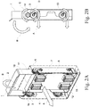
- second gear 14 With respect to first gear 3 can be better understood in connection with FIGS. 2A and 2B , and FIGS. 3A and 3B .
- second gear 14 moves in the same direction as handle 1.
- This rotation of second gear 14 is counterclockwise as shown in the direction of arrow C in Fig. 2B .
- This counterclockwise movement of second gear 14 causes first gear 3 to moves in a clockwise direction illustrated by arrow D.
- the clockwise movement of first gear 3 causes the first gear 3 to traverse along rack 4 causing the tray 5, carrying the plurality of connectors 10, 11, 12 and 15, to move horizontally as shown by arrow A in FIG. 2B .
- Rack 4 being fixedly mounted in a horizontal position as illustrated in the FIGS. 1 , 2A , 2B , 3A, and 3B , causes tray 5, to which rack 4 is mounted, to move in a horizontal direction.
- the connectors 10, 11, 12, and 15, mounted on floor 8 of tray 5, move horizontally as well.
- first gear 3 and rack 4 may stabilize the movement of tray 5 in chassis 6.
- provision of a mirror image of first gear 3 and rack 4 at the opposite end of a U-shaped handle 1 facilitates the stabilization of horizontal movement.
- first gears 13 will move on racks 44, as shown in FIGS. 2B and 3B , but there will be no driving second gear in connection with first gears 13. Rather, a transfer bar 7 (only one shown in FIG. 1 for clarity) is connected between each pair of first gear 13 and first gear 3. Therefore, each first gear 13 will follow the associated rack 44, as influenced by the movement of the transfer bar 7 under the influence of the first gear 3.
- second gear 14 is illustrated as a separate element, it should be understood that second gear 14 may be made integral with handle 1. It should also be understood that the provision of a second gear 14 could be dispensed with entirely by providing the end of handle 1 with a gear like configuration of teeth, such that rotation of handle 1 directly drives and rotates first gear 3 without the need for a second gear 14. Furthermore, it should be understood that a mechanical advantage may be obtained by suitable configuring the relative sizes of first gear 3 and second gear 14 so as to achieve the desired mechanical advantage. It should be further understood that suitable configuring of the relative sizes of first gear 3 and second gear 14, and the number of teeth on each of the first gear 3 and second gear 14, could achieve an increase in the relative horizontal movement of first gear 3 upon rack 4, with a reduction of the degree of rotation of handle 1.
- the handle 1 may comprise other shapes without detracting from its ability to translate rotational movement into horizontal movement.
- the handle 1 may be L-shaped or may be linear in shape, so long as it is capable of pivotal movement and driving of first gear 3.
- horizontal movement can be a relative term depending on the orientation of the chassis.
- the movement of the tray 5 relative to the chassis 6 may be vertical, in an upwards or downwards direction.
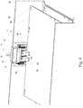
- multiple platforms 18, 28 may be contained within an enclosure 36.
- Chassis 6 is mounted upon flanges 20, 21 of enclosure 36.
- the platforms 18, 28 are each are provided with multiple connectors, such as connectors 30, 31 in FIG. 4 and connectors 40, 41 in FIG. 5 .
- the mechanism to convert the rotational movement of handle 1 into horizontal motion is basically the same as previously disclosed.
- Handle 1 is pivotably mounted on pivot 2 which is mounted on chassis 6, where flanges 20, 21 are affixed to enclosure 36.
- Flanges 20, 21 are fixed with enclosure 36 which function is guiding chassis 6.
- Rotation of second gear 14 causes first gear 3 to act as a pinion with rack 4 to move connectors 10 and 11 in a horizontal direction.
- movement of connectors 10 and 11 would bring them into contact with connectors 30, 31, respectively.
- lower platform 28 has connectors 40, 41, and movement of the handle 1 would also move connectors 12, 15 of FIG. 1 (not illustrated in FIG. 5 ) into contact with these connectors 40, 41, respectively.
- the movement of all connectors 10, 11, 12 and 15 is in unison.
- the contact of connectors 10, 11, 12 and 15 with their respective connectors 30, 31, 40, 41, respectively occurs simultaneously.
- Each of connectors 10, 11, 12, 15, 30, 31, 40 and 41 could be male and female connectors, touch connectors, pin and socket connectors, or other type of connectors known in the art.
Landscapes
- Engineering & Computer Science (AREA)
- General Engineering & Computer Science (AREA)
- Theoretical Computer Science (AREA)
- Microelectronics & Electronic Packaging (AREA)
- Computer Hardware Design (AREA)
- Power Engineering (AREA)
- Human Computer Interaction (AREA)
- Physics & Mathematics (AREA)
- General Physics & Mathematics (AREA)
- Mechanical Engineering (AREA)
- Details Of Connecting Devices For Male And Female Coupling (AREA)
- Transmission Devices (AREA)
Applications Claiming Priority (2)
| Application Number | Priority Date | Filing Date | Title |
|---|---|---|---|
| US201762607169P | 2017-12-18 | 2017-12-18 | |
| US15/918,247 US10487922B2 (en) | 2017-12-18 | 2018-03-12 | Horizontal motion mechanism in limited space |
Publications (1)
| Publication Number | Publication Date |
|---|---|
| EP3499338A1 true EP3499338A1 (de) | 2019-06-19 |
Family
ID=62981087
Family Applications (1)
| Application Number | Title | Priority Date | Filing Date |
|---|---|---|---|
| EP18183943.2A Withdrawn EP3499338A1 (de) | 2017-12-18 | 2018-07-17 | Mechanismus mit horizontaler bewegung in begrenztem raum |
Country Status (5)
| Country | Link |
|---|---|
| US (1) | US10487922B2 (de) |
| EP (1) | EP3499338A1 (de) |
| JP (1) | JP6694030B2 (de) |
| CN (1) | CN109928190A (de) |
| TW (1) | TWI642610B (de) |
Families Citing this family (2)
| Publication number | Priority date | Publication date | Assignee | Title |
|---|---|---|---|---|
| CN111007923A (zh) * | 2019-10-18 | 2020-04-14 | 苏州浪潮智能科技有限公司 | 一种免工具把手及带有免工具把手的一体机 |
| CN115437467A (zh) * | 2021-06-01 | 2022-12-06 | 纬联电子科技(中山)有限公司 | 托盘组件与包括托盘组件的电子装置 |
Citations (3)
| Publication number | Priority date | Publication date | Assignee | Title |
|---|---|---|---|---|
| US5010426A (en) * | 1989-02-03 | 1991-04-23 | Zenith Data Systems Corporation | Installation mechanism for removable computer drive module |
| US5721669A (en) * | 1995-09-15 | 1998-02-24 | Apple Computer, Inc. | Gear-driven docking apparatus for removable mass-storage drives |
| US9826658B1 (en) * | 2016-08-30 | 2017-11-21 | Wistron Corporation | Electronic device and tray |
Family Cites Families (6)
| Publication number | Priority date | Publication date | Assignee | Title |
|---|---|---|---|---|
| US5399156A (en) * | 1990-03-14 | 1995-03-21 | Minnesota Mining And Manufacturing Company | Quick-changeover blood handling apparatus |
| KR100574976B1 (ko) * | 2004-03-05 | 2006-05-02 | 삼성전자주식회사 | 트레이 이송장치 및 이를 적용한 디스크 드라이브 |
| US7251145B1 (en) * | 2004-08-18 | 2007-07-31 | Sun Microsystems, Inc. | Inject/eject mechanism for circuit boards |
| TWI457057B (zh) * | 2011-11-30 | 2014-10-11 | Ibm | 電路板總成,具有電路板總成的電子設備,及其升降裝置 |
| CN102738685B (zh) * | 2012-06-21 | 2014-09-17 | 华为技术有限公司 | 电路板的插拔装置及服务器 |
| CN202906099U (zh) * | 2012-09-03 | 2013-04-24 | 泰科电子(上海)有限公司 | 带有杠杆机构的连接器及连接器组件 |
-
2018
- 2018-03-12 US US15/918,247 patent/US10487922B2/en active Active
- 2018-05-24 TW TW107117801A patent/TWI642610B/zh active
- 2018-06-19 CN CN201810630199.4A patent/CN109928190A/zh active Pending
- 2018-07-17 EP EP18183943.2A patent/EP3499338A1/de not_active Withdrawn
- 2018-09-05 JP JP2018165974A patent/JP6694030B2/ja active Active
Patent Citations (3)
| Publication number | Priority date | Publication date | Assignee | Title |
|---|---|---|---|---|
| US5010426A (en) * | 1989-02-03 | 1991-04-23 | Zenith Data Systems Corporation | Installation mechanism for removable computer drive module |
| US5721669A (en) * | 1995-09-15 | 1998-02-24 | Apple Computer, Inc. | Gear-driven docking apparatus for removable mass-storage drives |
| US9826658B1 (en) * | 2016-08-30 | 2017-11-21 | Wistron Corporation | Electronic device and tray |
Also Published As
| Publication number | Publication date |
|---|---|
| CN109928190A (zh) | 2019-06-25 |
| TWI642610B (zh) | 2018-12-01 |
| US20190186603A1 (en) | 2019-06-20 |
| JP2019110107A (ja) | 2019-07-04 |
| TW201927658A (zh) | 2019-07-16 |
| JP6694030B2 (ja) | 2020-05-13 |
| US10487922B2 (en) | 2019-11-26 |
Similar Documents
| Publication | Publication Date | Title |
|---|---|---|
| EP3499338A1 (de) | Mechanismus mit horizontaler bewegung in begrenztem raum | |
| JP2017224599A (ja) | 端子曲げユニットおよび端子曲げ装置 | |
| EP2346117B1 (de) | Linear betätigte, zusammengehörende Verbinderschnittstelle | |
| CN107599393B (zh) | 用于3d打印机的双喷头切换装置 | |
| CN108656105B (zh) | 自动取料设备 | |
| HUP0102431A2 (hu) | Két rudas/csuklós mechanizmust tartalmazó szerkezet | |
| US9831645B2 (en) | Spring loaded, bistable connect/disconnect for MCC unit | |
| CN105745800A (zh) | 开关柜 | |
| US20050268987A1 (en) | Robotic system and method for transport of materials with minimization of footprint size | |
| CN207801244U (zh) | 一种双面出线配电箱 | |
| JPWO2008072397A1 (ja) | パネル駆動装置 | |
| JPH07205067A (ja) | 物品の移送機構 | |
| CN107962581A (zh) | 双段滑杆支撑式末端直线平夹自适应机器人手指装置 | |
| CN107414809B (zh) | 一种机械臂 | |
| WO2014180586A1 (en) | Spring transfer device and spring transfer method | |
| CN215374289U (zh) | 一种热学实验用测温设备 | |
| CN115061530B (zh) | 一种用于无人机的3d摇杆 | |
| CN120703700A (zh) | 可全向调节的脚踢测试设备 | |
| CN207925335U (zh) | 一种双电源切换方向装置 | |
| CN108012496B (zh) | 板组件以及电子设备 | |
| CN207165734U (zh) | 一种阵列式宽频多波束天线 | |
| KR20170035122A (ko) | 델타 로봇을 이용하는 3d 프린터 | |
| CN113146597B (zh) | 一种机械手 | |
| CN219094211U (zh) | 一种开关全自动组装机构 | |
| CN221342950U (zh) | 一种龙门式码垛机机械手 |
Legal Events
| Date | Code | Title | Description |
|---|---|---|---|
| PUAI | Public reference made under article 153(3) epc to a published international application that has entered the european phase |
Free format text: ORIGINAL CODE: 0009012 |
|
| STAA | Information on the status of an ep patent application or granted ep patent |
Free format text: STATUS: THE APPLICATION HAS BEEN PUBLISHED |
|
| AK | Designated contracting states |
Kind code of ref document: A1 Designated state(s): AL AT BE BG CH CY CZ DE DK EE ES FI FR GB GR HR HU IE IS IT LI LT LU LV MC MK MT NL NO PL PT RO RS SE SI SK SM TR |
|
| AX | Request for extension of the european patent |
Extension state: BA ME |
|
| STAA | Information on the status of an ep patent application or granted ep patent |
Free format text: STATUS: REQUEST FOR EXAMINATION WAS MADE |
|
| 17P | Request for examination filed |
Effective date: 20190829 |
|
| RBV | Designated contracting states (corrected) |
Designated state(s): AL AT BE BG CH CY CZ DE DK EE ES FI FR GB GR HR HU IE IS IT LI LT LU LV MC MK MT NL NO PL PT RO RS SE SI SK SM TR |
|
| STAA | Information on the status of an ep patent application or granted ep patent |
Free format text: STATUS: EXAMINATION IS IN PROGRESS |
|
| 17Q | First examination report despatched |
Effective date: 20200512 |
|
| STAA | Information on the status of an ep patent application or granted ep patent |
Free format text: STATUS: THE APPLICATION IS DEEMED TO BE WITHDRAWN |
|
| 18D | Application deemed to be withdrawn |
Effective date: 20211126 |