EP3499330A1 - Management system, management device, management method, and program - Google Patents
Management system, management device, management method, and program Download PDFInfo
- Publication number
- EP3499330A1 EP3499330A1 EP18194546.0A EP18194546A EP3499330A1 EP 3499330 A1 EP3499330 A1 EP 3499330A1 EP 18194546 A EP18194546 A EP 18194546A EP 3499330 A1 EP3499330 A1 EP 3499330A1
- Authority
- EP
- European Patent Office
- Prior art keywords
- abnormality
- product
- information
- cause
- device member
- Prior art date
- Legal status (The legal status is an assumption and is not a legal conclusion. Google has not performed a legal analysis and makes no representation as to the accuracy of the status listed.)
- Granted
Links
Images




Classifications
-
- G—PHYSICS
- G05—CONTROLLING; REGULATING
- G05B—CONTROL OR REGULATING SYSTEMS IN GENERAL; FUNCTIONAL ELEMENTS OF SUCH SYSTEMS; MONITORING OR TESTING ARRANGEMENTS FOR SUCH SYSTEMS OR ELEMENTS
- G05B19/00—Program-control systems
- G05B19/02—Program-control systems electric
- G05B19/418—Total factory control, i.e. centrally controlling a plurality of machines, e.g. direct or distributed numerical control [DNC], flexible manufacturing systems [FMS], integrated manufacturing systems [IMS] or computer integrated manufacturing [CIM]
- G05B19/41875—Total factory control, i.e. centrally controlling a plurality of machines, e.g. direct or distributed numerical control [DNC], flexible manufacturing systems [FMS], integrated manufacturing systems [IMS] or computer integrated manufacturing [CIM] characterised by quality surveillance of production
-
- G—PHYSICS
- G05—CONTROLLING; REGULATING
- G05B—CONTROL OR REGULATING SYSTEMS IN GENERAL; FUNCTIONAL ELEMENTS OF SUCH SYSTEMS; MONITORING OR TESTING ARRANGEMENTS FOR SUCH SYSTEMS OR ELEMENTS
- G05B2219/00—Program-control systems
- G05B2219/30—Nc systems
- G05B2219/32—Operator till task planning
- G05B2219/32177—Computer assisted quality surveyance, caq
-
- G—PHYSICS
- G05—CONTROLLING; REGULATING
- G05B—CONTROL OR REGULATING SYSTEMS IN GENERAL; FUNCTIONAL ELEMENTS OF SUCH SYSTEMS; MONITORING OR TESTING ARRANGEMENTS FOR SUCH SYSTEMS OR ELEMENTS
- G05B2219/00—Program-control systems
- G05B2219/30—Nc systems
- G05B2219/37—Measurements
- G05B2219/37514—Detect normality, novelty in time series for online monitoring
-
- Y—GENERAL TAGGING OF NEW TECHNOLOGICAL DEVELOPMENTS; GENERAL TAGGING OF CROSS-SECTIONAL TECHNOLOGIES SPANNING OVER SEVERAL SECTIONS OF THE IPC; TECHNICAL SUBJECTS COVERED BY FORMER USPC CROSS-REFERENCE ART COLLECTIONS [XRACs] AND DIGESTS
- Y02—TECHNOLOGIES OR APPLICATIONS FOR MITIGATION OR ADAPTATION AGAINST CLIMATE CHANGE
- Y02P—CLIMATE CHANGE MITIGATION TECHNOLOGIES IN THE PRODUCTION OR PROCESSING OF GOODS
- Y02P90/00—Enabling technologies with a potential contribution to greenhouse gas [GHG] emissions mitigation
- Y02P90/02—Total factory control, e.g. smart factories, flexible manufacturing systems [FMS] or integrated manufacturing systems [IMS]
Definitions
- the disclosure relates to a technology for detecting abnormality of manufacturing equipment which is a cause or a sign of defect occurrence.
- inspection devices are installed in intermediate processes or final processes of the lines to automate detection of defects, sorting of defective products, or the like.
- attempts to estimate causes of defects from inspection results of the inspection devices and utilize the causes of the defects in quality management or maintenance of manufacturing equipment have been made.
- Patent Document 1 discloses an idea to present information of nozzles deteriorating quality levels by aggregating proportion defectives in the final inspection after a reflow according to the nozzles of a mounter device.
- Patent Document 2 proposes a method of calculating proportion defectives of components in inspection after a reflow according to nozzles and feeders of a mounter device and detecting a nozzle or a feeder in which abnormality is detected according to whether the proportion defectives exceed proportion defectives at a normal time.
- the disclosure is devised in view of the foregoing circumstances and an objective of the disclosure is to provide a technology for specifically identifying whether one of a device member, a component, and a combination of the device member and the component is a direct cause of a defect in manufacturing equipment of products and causing maintenance and quality management of equipment to be efficient.
- a management system of manufacturing equipment that manufactures a product.
- the manufacturing equipment includes one or more manufacturing devices including one or more device members and one or more inspection units that inspect a quality of the product.
- the management system includes: a product member information acquisition unit configured to acquire product member information for each product member included in the product; a device member information acquisition unit configured to acquire device member information regarding each device member of the manufacturing device; a quality information acquisition unit configured to acquire quality information regarding each product member including an inspection result obtained by the inspection unit; and an abnormality analysis unit configured to determine whether there is abnormality in one of the device member, the product member, a combination of the device member and the product member, a combination of the device member and the device member information, and a combination of the device member, the device member information, and the product member and identify a cause of the abnormality, using the quality information.
- the "manufacturing equipment” is general equipment that manufactures a product and is, for example, a manufacturing factory, a production line, or a manufacturing device.
- the "manufacturing device” is any of various devices that manufacture products and includes, for example, each device of a printed board production line, such as a solder printer, a mounter, or a reflow furnace, a manufacturing device of various product members included in a printed board, and a manufacturing device of solder.
- the "manufacturing member” is any of various members and mechanism included in a manufacturing device and includes, for example, a nozzle, a head, a feeder, a camera, a pump, and a stage in a mounter device.
- the "product member” is each element included in a product and includes, for example, an electronic product member such as an IC chip, a printed wiring plate (so-called raw circuit board), and solder on a printed board.
- the "inspection unit” is, for example, a unit that performs inspection such as automatic optical inspection (AOI) or automatic X-ray inspection (AXI) and may be an inspection unit that reflects information regarding visual inspection. An inspection unit may be contained in the manufacturing device.
- AOI automatic optical inspection
- AXI automatic X-ray inspection
- the foregoing "product member information” is information regarding a product member and includes, for example, a component number, a reel ID, a manufacturing lot of the product member, a type of product member, the shape of the product member, and the position of the product member on a board.
- the "device member information” is information regarding a device member and includes, for example, a type of device member, a model of the device member, a device member ID, an activation time of the device member, the number of times the device member is activated, and a mounting parameter.
- the mounting parameter includes, for example, the position of a feeder of a mounter in a mounter device, an adsorption height of the mounter, and a head speed of the mounter.
- the "quality information" is information regarding a quality of a product and includes a measured value of performed inspection and a phenomenon (for example, an X axis deviation, a Y axis deviation, an angle deviation, a product member inclination, or product member rising) ascertained from the measured value. Additionally, for example, the quality information may include a proportion defective of a product, a defective number of products, the number of defects per product, a defect occurrence situation in a more downstream process in which the product is used, and a process capability. The process capability will be described below in detail.
- each product member included in a product does not mean component one by one used in one product, but means, for example, each product which can be identified on a condition such as the same type of product member disposed at a predetermined spot of a predetermined product.
- the quality information acquisition unit may be the inspection unit in a final inspection process of the product.
- information regarding inspection performed in a stage in which the product state is decided can be used, and thus quality information in which a genuine state of the product in the process is reflected can be acquired.
- the abnormality analysis unit may identify the cause and determine whether there is the abnormality in one of the device member, the product member, the combination of the device member and the product member, the combination of the device member and the device member information, the combination of the device member, the device member information, and the product member.
- a combination of the product member information and the device combination information can be analyzed using the quality information, and abnormality and a cause can be found in each combination of the product member information and the device member information.
- the abnormality analysis unit may include an abnormality determination unit configured to determine whether there is the abnormality for each product member included in the product based on the quality information, and an abnormality cause identifying unit configured to identify whether there is the cause of the abnormality in one of the combination of the device member and the device member information and the combination of the device member, the device member information, and the product member based on the quality information, the device member information, and the device member information when the abnormality determination unit determines that there is the abnormality in one of the product members included in the product.
- abnormality can be found using only the quality information. Further, the cause of the abnormality can be identified as necessary.
- the abnormality analysis unit may determine whether there is the abnormality in each of the product members.
- the quality index is, for example, an index related to a quality determined using an inspection result (for example, a measured value of an X axis position) of each of the plurality of component members processed by a device and a management standard (for example, an allowable threshold of an X axis deviation of the product member) serving as a determination standard of a defective product.
- a management standard for example, an allowable threshold of an X axis deviation of the product member
- the manufacturing device in the manufacturing equipment may include a plurality of device members.
- the abnormality analysis unit may first identify a device member in which the product member for which it is determined that there is the abnormality is handled, and when there is the same type of different device member in which the same type of product member as the device member in which the product member for which it is determined that there is the abnormality is handled, the abnormality analysis unit may further identify a cause of the abnormality by comparing presence or absence of the abnormality in a combination of the different device member and the product member to presence or absence of the abnormality in the combination of the product member and the device member in which the product member for which it is determined that there is the abnormality is handled.
- the manufacturing device in the manufacturing equipment may include a plurality of device members.
- the abnormality analysis unit first identifies a device member in which the product member for which it is determined that there is the abnormality is handled, and when there is the same type of different device member in which the same type of product member as the product member for which it is determined that there is the abnormality is handled, the abnormality analysis unit further identifies a cause of the abnormality by comparing device member information of the different product member to device member information of the device member in which the product member for which it is determined that there is the abnormality is handled.
- the abnormality analysis unit may automatically determine whether there is the abnormality in each of the product members, and abnormality cause identifying unit may automatically identify the cause of the abnormality.
- abnormality cause identifying unit may automatically identify the cause of the abnormality.
- the management system may further include an abnormality cause solution unit configured to perform a process of solving the cause of the abnormality wherein, when the abnormality analysis unit identifies the cause of the abnormality.
- an abnormality cause solution unit configured to perform a process of solving the cause of the abnormality wherein, when the abnormality analysis unit identifies the cause of the abnormality.
- the process performed by the abnormality cause solution unit may cause the manufacturing device to perform a method of solving the cause of the abnormality identified by the abnormality cause identifying unit, may present the method of solving the identified cause of the abnormality to a user, or may cause the manufacturing device to perform the method of solving the identified cause of the abnormality by a permission given by the user.
- the user examines and performs a method of solving the cause of the abnormality from the beginning, it is also possible to shorten a time necessary to solve the cause of the abnormality.
- the management system may further include an output unit.
- the output unit outputs the quality information regarding the product members included in the product for each device member and/or each product member.
- the output unit may be a display device and the quality information regarding the product members included in the product may be output visually. In this configuration, the user can confirm the quality information, and thus appropriate determination can be performed when decision related to the process of solving the cause of the abnormality can be performed.
- the "output unit” is not limited to a display device, and any output unit such as a speaker, a printer, and a communication device is included.
- the visually output information may be information expressed in a sentence, may be numerical information, or may be expressed with a graph.
- the manufacturing equipment may be a surface mount line of a printed board.
- the manufacturing device may be one of a solder printer, a mounter, and a reflow furnace.
- the quality information acquisition unit may be an inspection unit after a reflow.
- the mounter In the manufacturing equipment of the surface mount line, in particular, the mounter, a plurality of types of device members such as a nozzle, a head, a feeder, a camera, a pump, and a stage perform various operations. Therefore, it is not easy to identify a cause of abnormality. Thus, the disclosure functions efficiently.
- the disclosure can be ascertained as a management device including at least some of the foregoing units.
- the disclosure can also be ascertained as the system, a quality management method by a device, a computer program causing a computer to execute each step of the method, or a computer-readable storage medium that non-transitorily stores the program.
- the foregoing configurations and processes can each be combined to each other to realize the disclosure as long as technical contradiction does not occur.
- the disclosure it is possible to provide a technology for specifically identifying whether one of a device member, a product member, and a combination of the device member and the product member is a direct cause of a defect in manufacturing equipment of products and causing maintenance and quality management of equipment to be efficient.
- the disclosure can be applied as, for example, a quality management system 9 illustrated in FIG. 6 .
- the quality management system 9 is a management system for managing a quality of a mounter in a surface mount line of a printed board and includes a mounter 91 and a component inspection device 92 as constituent elements.
- the mounter 91 is a device that picks up an electronic component to be mounted on a board and mounts components on a solder paste of corresponding spots and is also referred to as a chip mounter.
- the component inspection device 92 is a device that inspects disposition states of electronic components on a board carried out from the mounter 91.
- the component inspection device 92 measures disposition states of components (which may be some of components such as component bodies and electrodes) placed on a solder paste 2-dimensionally or 3-dimensionally and determines whether the disposition states have normal values (allowable ranges) of various inspection items from the measurement results.
- the quality management system 9 includes a component information acquisition unit 921, a device member information acquisition unit 922, a quality information acquisition unit 923, an abnormality analysis unit 924, an abnormality cause solution unit 925, and an information output unit 926, and these functions are mounted on the component inspection device 92.
- the component information acquisition unit 921 has a function of acquiring information regarding components such as various electronic components, a board, and solders used in the mounter 91.
- the device member information acquisition unit 922 has a function of acquiring information regarding various members or mechanisms included in the mounter.
- the quality information acquisition unit 923 has a function of acquiring information regarding an inspection result.
- the abnormality analysis unit 924 has a function of analyzing and identifying a cause of the abnormality when there is abnormality in any of the components mounted on the board by the mounter 91.
- the abnormality cause solution unit 925 has a function of performing a process to solve the identified cause.
- the information output unit 926 has a function of outputting quality information regarding each component or information regarding an abnormality occurrence spot, a method of solving an abnormality cause, and the like.
- the quality information acquisition unit 923 acquires inspection result information (step S101). Further, the component information acquisition unit 921 and the device member information acquisition unit 922 acquire component information and the device member information (step S102). Then, based on the information, it is determined whether there is abnormality in each combination of a component number and a device member (for example, a feeder) included in the mounter (step S103).
- a quality index is calculated using a measured value (for example, an X axis position) of each of a plurality of mounted components and a predetermined management standard (for example, an allowable threshold of an X axis deviation of a component). It is determined that there is the abnormality when the quality index exceeds a predetermined standard. It is determined that there is no abnormality when the quality index does not exceed the predetermined standard.
- the determination standard is preferably determined as a strict standard compared to the management standard from the viewpoint of the fact that abnormality of manufacturing equipment is found before a defective product is actually generated and a cause of the abnormality is identified and treated.
- the X axis deviation of a component mounted by the mounter has been exemplified above.
- correspondence to each inspection item can be decided from a measured value of each of the various inspection items.
- step S103 When the combination in with the abnormality is not found in step S103, the process is terminated temporarily. Conversely, when the combination with the abnormality is found in step S103, the process proceeds to step S104.
- step S104 it is determined whether the number of combinations with the abnormality is one pair or a plurality of pairs.
- the number of combinations with the abnormality is plural, it is identified that there is a cause of the abnormality in the device member and the process ends (step S105). Conversely, when there is only one combination with the abnormality in step S104, the process proceeds to step S106.
- step S106 it is confirmed whether a component number of the component with abnormality is also mounted on the same type of different device members.
- the process is terminated temporarily (step S107).
- step S106 when the component number of the component with the abnormality is mounted on the same type of plurality of device members in step S106, it is determined whether there is the abnormality in each combination of the component number and the device member (step S108).
- step S108 when there is only one combination with the abnormality, it is identified that there is a cause of the abnormality in the combination of the device member and the component number and the process ends (step S109). Conversely, when the number of combinations with the abnormality is plural in step S108, it is identified that there is the cause of the abnormality in the component and the process is terminated (step S110).
- the abnormality cause solution unit 925 performs a process of solving the cause of the abnormality in accordance with the identified cause. For example, when there is the cause of the abnormality in the device member, the information output unit 926 notifies a user of maintenance (including exchange) of the device member. When there is the cause of the abnormality in the combination of the device member and the component number, for example, a command may be transmitted to the mounter 91 so that such mounting parameters are changed to appropriate values.
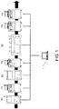
- FIG. 1 schematically illustrates a configuration example of manufacturing equipment and a quality management system in a surface mount line of a printed board.
- Surface mount surface mount technology: STM
- STM surface mount technology
- the surface mount line mainly includes three processes of solder printing, mounting of components, and a reflow (welding of solder).
- a solder printing device X1 is a device that prints solder on a paste to an electrode portion (referred to as a land) on a printed board by screen printing.
- the mounter X2 is a device that picks up an electronic component to be mounted on a board and places the component on the solder paste of the corresponding spot and is also referred to as a chip mounter.
- the reflow furnace X3 is a heating device that heats and melts the solder paste, subsequently performs cooling, and solders and bonds the electronic component on the board.
- the plurality of mounters X2 are provided in the surface mount line.
- the quality management system In the surface mount line, a quality management system that inspects a board state at an exit of each process of the solder printing, the mounting of the components, and the reflow and automatically detects a defect or concern of the defect is provided.
- the quality management system also has a function of feeding back an operation of each manufacturing device (for example, changing a mounting program) based on an inspection result or the analysis result in addition to automatic sorting of good products and defective products.
- the quality management system includes the management device 1 and four types of inspection devices, that is, a solder printing inspection device Y1, a component inspection device Y2, an exterior inspection device Y3, an X-ray inspection device Y4.
- the solder printing inspection device Y1 is a device that inspects a printing state of the solder paste on the board carried out from the solder printing device X1.
- the solder printing inspection device Y1 measures the solder paste printed on the board 2-dimensionally or 3-dimensionally and determines whether the solder paste has normal values (allowable ranges) of various inspection items from the measurement result.
- the inspection items for example, there are a volume, an area, a height, a position deviation, and a shape of the solder.
- an image sensor (camera) or the like can be used.
- a laser displacement sensor, a phase shift method, a space coding method, a space switching method, or the like can be used.
- the component inspection device Y2 is a device that inspects disposition states of electronic components on the board carried out from the mounter X2.
- the component inspection device Y2 measures components (some of the components such as component bodies and electrodes) placed on the solder paste 2-dimensionally or 3-dimensionally, and determines whether the components have normal values (allowable ranges) of various inspection items from the measurement results.
- the inspection items for example, there are a position deviation of the components, an angle (rotation) deviation, a defective product (components are not disposed), a component difference (different components are disposed), a polarity difference (polarities of electrodes on a component side and a board side are different), front-back inversion (components are disposed in the back direction), and a component height.
- an image sensor (camera) or the like can be used.
- a laser displacement sensor In the 3-dimensional measurement, a laser displacement sensor, a phase shift method, a space coding method, a space switching method, or the like can be used.
- the exterior inspection device Y3 is a device that inspects qualities of solder portions on the board carried out from the reflow furnace X3.
- the exterior inspection device Y3 measures the solder portions after a reflow 2-dimensionally or 3-dimensionally and determines whether the solder portion has normal values (allowable ranges) of various inspection items from the measurement result.
- the inspection items include a quality or the like of a solder fillet shape in addition as the same items as the component inspection.
- a so-called color highlight scheme (a method of detecting a 3-dimensional shape of solder as 2-dimensional color information by lighting R, G, and B to a solder surface at different incident angles and imaging reflected light of each color using a zenith camera) can be used in addition to the laser displacement sensor, the phase shift method, the space coding method, the space switching method, or the like described above.
- the X-ray inspection device Y4 is a device that inspects states of solder portions on the board using an X-ray image. For example, in the case of a multi-layered board or a package component such as a ball grid array (BGA) or a chip size package (CSP), a solder bonding portion is hidden in components or below a board. Therefore, solder states may not be inspected by the exterior inspection device Y3 (that is, in an exterior image).
- the X-ray inspection device Y4 is a device that complements weakness of such exterior inspection.
- inspection items of the X-ray inspection device Y4 there are a position deviation of component, a solder height, a solder volume, a solder ball diameter, the length of a back fillet, and a quality of solder bonding.
- an X-ray image an X-ray transmission image may be used or a computed tomography (CT) mage may be preferably used.
- CT computed tomography
- the manufacturing devices X1 to X3 and the inspection devices Y1 to Y4 described above are connected to the management device 1 via a network (LAN).
- the management device 1 is a system that serves as managing or controlling the manufacturing devices X1 to X3 and the inspection devices Y1 to Y4 and is configured as a general-purpose computer system that includes a CPU (processor), a main storage device (a memory), an auxiliary storage device (a hard disk or the like), an input device (a keyboard, a mouse, a controller, a touch panel, and the like), and a display device.
- the function of the management device 1 to be described below is realized by causing a CPU to read a program stored in the auxiliary storage device and execute the program.
- the management device 1 may be configured by one computer or may be configured by a plurality of computers. Alternatively, some or all of the functions of the management device 1 can also be mounted on a computer contained in one device of the manufacturing devices X1 to X3 or the inspection devices Y1 to Y4. Alternatively, some of the functions of the management device 1 may be realized by a server (a cloud server or the like) on a network.
- a server a cloud server or the like
- the management device 1 has a function of identifying a cause of abnormality (hereinafter referred to as an abnormality cause identifying function) when the abnormality occurs in a quality of the printed board obtained from the inspection performed in the inspection devices Y1 to Y4, and a function of solving the identified cause of the abnormality (hereinafter referred to as an abnormality cause solution function).
- FIG. 2 is a block diagram illustrating functions of the management device 1.
- the management device 1 includes a component information acquisition unit 10, a component information database (DB) 11, a device member information acquisition unit 12, a device member information DB 13, a manufacturing log information acquisition unit 14, a manufacturing log information DB 15, a quality information acquisition unit 16, a quality information DB 17, an abnormality analysis unit 18, and an information output unit 19.
- the component information acquisition unit 10 is a function of acquiring information regarding components such as various electronic components, a board, and solder used in the surface mount line.
- the component information DB 11 is a storage unit that stores component information.
- the device member information acquisition unit 12 is a function of acquiring information regarding various members or mechanisms included in the manufacturing devices X1 to X3.
- the device member information DB 13 is a storage unit that stores device member information.
- the manufacturing log information acquisition unit 14 is a function of acquiring manufacturing log information from the manufacturing devices X1 to X3.
- the manufacturing log information DB 15 is a storage unit that stores the manufacturing log information.
- the quality information acquisition unit 16 is a function of acquiring the inspection result information from the inspection devices Y1 to Y4.
- the quality information DB 17 is a storage unit that stores quality information including the inspection result information.
- the abnormality analysis unit 18 is a function of determining a component in which there is abnormality among the components on the printed board from the inspection result information, the manufacturing log information, the device member information, and the component information and identifying a cause of the abnormality when there is the abnormality.
- An abnormality cause solution unit 181 is a function of performing a process of solving the identified cause.
- the information output unit 19 is a function of outputting information such as quality information, an abnormality occurrence spot, or a method of solving the cause of the abnormality of each component included in a printed board for each device member or each number of the component.
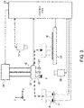
- FIG. 3 is a diagram schematically illustrating a configuration of the mounter X2.
- the mounter X2 includes a stage 20 on which a board B is placed, a plurality of feeders 21 that supply an electronic component P, a movable head 22 that picks up the electronic component P, a plurality of nozzles 23 mounted on the head 22, and a vacuum pump 24 that controls an air pressure of each nozzle.
- the electronic component P with a different number is set in the feeder 21 in each row.
- the mounter X2 includes an upper camera 25, a lower camera 26, a contact sensor 27 that measures a contact pressure on a nozzle end surface, and a pressure sensor 28 that measures an air pressure of the nozzle as an observation system that detects abnormality of an operation of the mounter X2.
- a control unit 29 is a block that processes control, calculation, and information processing of each unit of the mounter X2 and includes a CPU (processor) and a memory.
- the control unit 29 may include an output device that outputs information.
- the X and Y axes are taken to be parallel to the surface of the board and the Z axis is taken to be vertical to the surface of the board.
- the control unit 29 controls each nozzle 23 in accordance with the mounting program such that the necessary electronic components P are adsorbed and transported from the feeders 21 and are disposed on the board B in sequence.
- the board B is carried out to a downstream process (the inspection device Y2).
- the inspection device Y2 As manufacturing information of the board B, a board ID, a component number of each component, a circuit number, and manufacturing lot information associated with information (a nozzle ID and a feeder ID) indicating a device member processing each component are recorded in a memory of the mounter X2.
- the component information acquisition unit 10 acquires information regarding the components and stores the information in the component information DB 11.
- the information can be acquired at any timing. For example, when components are newly introduced to the production line or components with manufacturing lot differences of existing component numbers are input to the production line, the information may be acquired.
- a method of acquiring the information may be, for example, a method of automatically acquiring information from the server of a component maker via a network or may be a method of acquiring information input by a user.
- the device member information acquisition unit 12 acquires information regarding the device member and stores the information in the device member information DB 13.
- the information can be acquired at any timing. For example, when the device member is exchanged or maintenance or the like is performed or a new device member is introduced to the production line, the information may be acquired.
- a method of acquiring the information may be, for example, a method of automatically acquiring information from the server of a manufacturing device maker via a network or may be a method of acquiring information input by a user.
- the manufacturing log information acquisition unit 14 acquires manufacturing log information from the mounter X2 and stores the manufacturing log information in the manufacturing log information DB 15.
- the manufacturing log information can be acquired at any timing. For example, whenever mounting of a board in the mounter X2 is completed, the control unit 29 of the mounter X2 may transmit the manufacturing log information to the management device 1. Alternatively, the manufacturing log information acquisition unit 14 may acquire information at a time or a frequency decided in advance or may acquire information in response to an acquisition request from a user.
- FIG. 4 illustrates an example of the manufacturing log information acquired from the mounter X2.
- Each row is a manufacturing record of one component and includes information such as a board ID, a component number, a circuit number, a nozzle ID, a feeder ID, and mounting start and completion times.
- the manufacturing log information it is possible to know a device member (a nozzle and a feeder) by which each component on the board is manufactured.
- the quality information acquisition unit 16 acquires inspection result information from the inspection devices Y1 to Y4 and stores the inspection result information in the quality information DB 17.
- the inspection result information can be acquired at any timing. For example, whenever inspection is performed by each inspection device, each inspection device may transmit inspection result information to the management device 1. Alternatively, the quality information acquisition unit 16 may acquire information from each inspection device at a time or a frequency decided in advance or may acquire information from the inspection device in response to an acquisition request from a user.
- the quality information may include an inspection result, that is, a defective or good determination result in addition to a measured value of inspection by each inspection device.
- types of defects may be included.
- a quality index such as a process capability may be included as quality information.
- the process capability is a capability to produce a product within a determined specification limit. As process capability indexes, there are Cpk and Cp.
- Cpk is calculated using pieces of inspection result information of a plurality of products by the following expression:
- CP (upper-side specification value - lower-side specification value)/6 ⁇
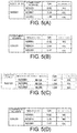
- FIG. 5(A) is a diagram illustrating a correspondent relation among the component information, the device member information, and the quality information when three component numbers of 123123, 123667, and 123903 are mounted on the nozzle with an ID NZ0001.
- a value of Cpk as a quality index and an abnormality presence or absence result obtained using the value of Cpk as a determination standard for presence or absence of abnormality are displayed.
- a determination standard value of Cpk is 1.33.
- Figs. 5(B) to 5(D) are diagrams illustrating correspondent relations among the component information, the device member information, and the quality information when the component with the component number 123123 is mounted on the nozzles with the IDs, NZ0001, NZ0024, and NZ0203.
- Cpk is less than 1.33 in only the combination of the component number 123123 and the nozzle ID of NZ0001, it is determined that there is a problem in only this combination. In this case, it can be identified that there is no cause of abnormality in both the nozzle with ID NZ0001 and the component with the component number 123123 and there is the problem in this combination.
- the nozzle type information obtained from the device member information is compared for the nozzles of NZ0001, NZ0024, and NZ0203. Then, it can be known that the type of nozzle is N12B for only NZ0203 and is different from that of the other two nozzles, and there is abnormality. In this case, it can be identified that there is a cause in the combination of the component number 123123 and the type of nozzle N12B. Additionally, a cause of abnormality may be identified by comparing mounting parameter of each nozzle as the device member information. In this case, when a mounting parameter is different from other mounting parameters and there is abnormality, it can be identified that there is a problem in the mounting parameter.
- the abnormality cause solution unit 181 causes the information output unit 19 to output information for solving the cause of the abnormality as an example of the process of solving the cause of the abnormality.
- a message "Please confirm mounting parameters of nozzle ID NZ0001 and component number 100222" is displayed on the display device.
- the abnormality cause solution unit 181 may acquire appropriate mounting parameters of the nozzle ID NZ0001 and the component number 100222 from the server and may automatically change the mounting parameters. Further, before the mounting parameters are changed, a user may be requested to permit the change. For example, a message "Mounting parameters of nozzle ID NZ0001 and component number 100222 are changed to appropriate values. Is it OK?" may be displayed on the display device and a user manipulation may be received.
- the abnormality cause solution unit 181 does not necessarily perform the process of solving a cause of abnormality even when the cause of the abnormality is identified. For example, when cost of the solution to a cause of abnormality is greater than cost of prevention of the cause of the abnormality, it is not necessary to immediately perform the process of solving the cause of the abnormality. Whether the process of solving the cause of the abnormality is performed may be determined in accordance with, for example, a threshold determined in advance.
- the processes in the mounter have been exemplified, but a cause of abnormality can also be identified in the solder printing device or the reflow furnace in accordance with the same method and the cause of the abnormality can be solved.
- the surface mount line has been exemplified.
- the disclosure can be applied as long as a production line includes a manufacturing device and an inspection device. The disclosure can also be applied to a manufacturing device in which an inspection unit is combined.
Landscapes
- Engineering & Computer Science (AREA)
- General Engineering & Computer Science (AREA)
- Manufacturing & Machinery (AREA)
- Quality & Reliability (AREA)
- Physics & Mathematics (AREA)
- General Physics & Mathematics (AREA)
- Automation & Control Theory (AREA)
- Supply And Installment Of Electrical Components (AREA)
- General Factory Administration (AREA)
- Testing And Monitoring For Control Systems (AREA)
Abstract
Description
- The disclosure relates to a technology for detecting abnormality of manufacturing equipment which is a cause or a sign of defect occurrence.
- In production lines in which automation and labor saving have progressed, inspection devices are installed in intermediate processes or final processes of the lines to automate detection of defects, sorting of defective products, or the like. In addition, attempts to estimate causes of defects from inspection results of the inspection devices and utilize the causes of the defects in quality management or maintenance of manufacturing equipment have been made.
- For example, as an example of the related art regarding a surface mount line of a printed board, Patent Document 1 discloses an idea to present information of nozzles deteriorating quality levels by aggregating proportion defectives in the final inspection after a reflow according to the nozzles of a mounter device. In addition, Patent Document 2 proposes a method of calculating proportion defectives of components in inspection after a reflow according to nozzles and feeders of a mounter device and detecting a nozzle or a feeder in which abnormality is detected according to whether the proportion defectives exceed proportion defectives at a normal time.
-
- [Patent Document 1] Japanese Unexamined Patent Application Publication No.
2005-156156 - [Patent Document 2] Japanese Unexamined Patent Application Publication No.
2006-332461 - As in the foregoing example of the related art, when information such as a proportion defective according to members included in a manufacturing device (referred to as device members) is presented, there is a possibility of a clue for estimating a faulty spot. However, the fact known from this information is merely a fact that there are many defects in products processed by the device members and a conclusive evidence of whether direct causes of the defects in the device members are really in the products may not be obtained. In a mounter, for example, this is because a possibility of a cause being in a device member other than a nozzle or a feeder can be considered and a possibility of a cause being in another process such as a solder printing process or a reflow process can also be considered. In addition, a case in which there is no cause in a manufacturing device or a device member, a case in which there is a cause in a component, and a case in which a combination of a specific component and a specific device member is a cause can also be considered.
- Even when a device member which is a cause of a defect can be specified, which abnormality occurs in the device member occurs may not be specified in the method of the related art. Accordingly, even when a faulty spot can be known, the knowledge and experience of an expert were indispensable or adjustment work by trial and error was necessary in order to take appropriate measures to find and solve actually occurring abnormality. In a mounter, for example, even when a nozzle in which defects frequently occur is known, whether it is necessary to exchange the nozzle, whether the nozzle is cleaned or mounting of the nozzle is adjusted, or whether countermeasures are taken by modifying a mounting program of a mounter or countermeasures are taken in a device member or a component other than the nozzle may not be determined.
- The disclosure is devised in view of the foregoing circumstances and an objective of the disclosure is to provide a technology for specifically identifying whether one of a device member, a component, and a combination of the device member and the component is a direct cause of a defect in manufacturing equipment of products and causing maintenance and quality management of equipment to be efficient.
- In order to achieve the objective, there is provided a management system of manufacturing equipment that manufactures a product. The manufacturing equipment includes one or more manufacturing devices including one or more device members and one or more inspection units that inspect a quality of the product. The management system includes: a product member information acquisition unit configured to acquire product member information for each product member included in the product; a device member information acquisition unit configured to acquire device member information regarding each device member of the manufacturing device; a quality information acquisition unit configured to acquire quality information regarding each product member including an inspection result obtained by the inspection unit; and an abnormality analysis unit configured to determine whether there is abnormality in one of the device member, the product member, a combination of the device member and the product member, a combination of the device member and the device member information, and a combination of the device member, the device member information, and the product member and identify a cause of the abnormality, using the quality information.
- Here, the "manufacturing equipment" is general equipment that manufactures a product and is, for example, a manufacturing factory, a production line, or a manufacturing device. The "manufacturing device" is any of various devices that manufacture products and includes, for example, each device of a printed board production line, such as a solder printer, a mounter, or a reflow furnace, a manufacturing device of various product members included in a printed board, and a manufacturing device of solder. The "manufacturing member" is any of various members and mechanism included in a manufacturing device and includes, for example, a nozzle, a head, a feeder, a camera, a pump, and a stage in a mounter device. The "product member" is each element included in a product and includes, for example, an electronic product member such as an IC chip, a printed wiring plate (so-called raw circuit board), and solder on a printed board. The "inspection unit" is, for example, a unit that performs inspection such as automatic optical inspection (AOI) or automatic X-ray inspection (AXI) and may be an inspection unit that reflects information regarding visual inspection. An inspection unit may be contained in the manufacturing device.
- The foregoing "product member information" is information regarding a product member and includes, for example, a component number, a reel ID, a manufacturing lot of the product member, a type of product member, the shape of the product member, and the position of the product member on a board. The "device member information" is information regarding a device member and includes, for example, a type of device member, a model of the device member, a device member ID, an activation time of the device member, the number of times the device member is activated, and a mounting parameter. Here, the mounting parameter includes, for example, the position of a feeder of a mounter in a mounter device, an adsorption height of the mounter, and a head speed of the mounter. The "quality information" is information regarding a quality of a product and includes a measured value of performed inspection and a phenomenon (for example, an X axis deviation, a Y axis deviation, an angle deviation, a product member inclination, or product member rising) ascertained from the measured value. Additionally, for example, the quality information may include a proportion defective of a product, a defective number of products, the number of defects per product, a defect occurrence situation in a more downstream process in which the product is used, and a process capability. The process capability will be described below in detail.
- The phrase "each product member included in a product" mentioned herein does not mean component one by one used in one product, but means, for example, each product which can be identified on a condition such as the same type of product member disposed at a predetermined spot of a predetermined product.
- In this configuration, when there is abnormality in one of the product members included in a product, maintenance or quality management of the manufacturing equipment can be performed efficiently in order to identify whether there is a cause of the abnormality in a device member, a product member, and a combination of the device member and the product member.
- The quality information acquisition unit may be the inspection unit in a final inspection process of the product. In this configuration, information regarding inspection performed in a stage in which the product state is decided can be used, and thus quality information in which a genuine state of the product in the process is reflected can be acquired.
- Based on the quality information, the device member information, and the product member information, the abnormality analysis unit may identify the cause and determine whether there is the abnormality in one of the device member, the product member, the combination of the device member and the product member, the combination of the device member and the device member information, the combination of the device member, the device member information, and the product member. In this configuration, a combination of the product member information and the device combination information can be analyzed using the quality information, and abnormality and a cause can be found in each combination of the product member information and the device member information.
- The abnormality analysis unit may include an abnormality determination unit configured to determine whether there is the abnormality for each product member included in the product based on the quality information, and an abnormality cause identifying unit configured to identify whether there is the cause of the abnormality in one of the combination of the device member and the device member information and the combination of the device member, the device member information, and the product member based on the quality information, the device member information, and the device member information when the abnormality determination unit determines that there is the abnormality in one of the product members included in the product. In this configuration, abnormality can be found using only the quality information. Further, the cause of the abnormality can be identified as necessary.
- In accordance with a quality index generated based on the quality information, the abnormality analysis unit may determine whether there is the abnormality in each of the product members.
- Here, the quality index is, for example, an index related to a quality determined using an inspection result (for example, a measured value of an X axis position) of each of the plurality of component members processed by a device and a management standard (for example, an allowable threshold of an X axis deviation of the product member) serving as a determination standard of a defective product. In this configuration, by strictly setting the determination standard using the quality index, abnormality of the manufacturing equipment can be found, a cause of the abnormality can be identified, and countermeasure can be taken before a defective product is actually generated. Therefore, it is possible to prevent generation of a defective product in advance.
- The manufacturing device in the manufacturing equipment may include a plurality of device members. When it is determined that there is abnormality in one of the product members, the abnormality analysis unit may first identify a device member in which the product member for which it is determined that there is the abnormality is handled, and when there is the same type of different device member in which the same type of product member as the device member in which the product member for which it is determined that there is the abnormality is handled, the abnormality analysis unit may further identify a cause of the abnormality by comparing presence or absence of the abnormality in a combination of the different device member and the product member to presence or absence of the abnormality in the combination of the product member and the device member in which the product member for which it is determined that there is the abnormality is handled.
- The manufacturing device in the manufacturing equipment may include a plurality of device members. When it is determined that there is abnormality in one of the product members, the abnormality analysis unit first identifies a device member in which the product member for which it is determined that there is the abnormality is handled, and when there is the same type of different device member in which the same type of product member as the product member for which it is determined that there is the abnormality is handled, the abnormality analysis unit further identifies a cause of the abnormality by comparing device member information of the different product member to device member information of the device member in which the product member for which it is determined that there is the abnormality is handled.
- In this configuration, when there is the cause of the abnormality actually in the product member or the combination of the product member and the device member, there is a fault in the device member. Thus, it is possible to prevent wrong measures from being taken, such as unnecessary maintenance or exchange of a member, and thus it is possible to suppress occurrence of an unnecessary man-hour. The same "type" mentioned herein is not completely the same synonym as "product member classification" or "device member classification" and is a concept including, for example, a variance in a product number or a manufacturing lot.
- The abnormality analysis unit may automatically determine whether there is the abnormality in each of the product members, and abnormality cause identifying unit may automatically identify the cause of the abnormality. In this configuration, it is possible to determine abnormality and identify a cause of the abnormality with given precision irrespective of an experience or an ability of a user. Since a manipulation of determining the abnormality and identifying the cause of the abnormality is not necessary, it is possible to operate the manufacturing equipment efficiently.
- The management system may further include an abnormality cause solution unit configured to perform a process of solving the cause of the abnormality wherein, when the abnormality analysis unit identifies the cause of the abnormality. In this configuration, it is possible to shorten a time of a process until the cause of the abnormality is solved.
- The process performed by the abnormality cause solution unit may cause the manufacturing device to perform a method of solving the cause of the abnormality identified by the abnormality cause identifying unit, may present the method of solving the identified cause of the abnormality to a user, or may cause the manufacturing device to perform the method of solving the identified cause of the abnormality by a permission given by the user. In any of the processes, when the user examines and performs a method of solving the cause of the abnormality from the beginning, it is also possible to shorten a time necessary to solve the cause of the abnormality.
- The management system may further include an output unit. The output unit outputs the quality information regarding the product members included in the product for each device member and/or each product member. The output unit may be a display device and the quality information regarding the product members included in the product may be output visually. In this configuration, the user can confirm the quality information, and thus appropriate determination can be performed when decision related to the process of solving the cause of the abnormality can be performed.
- Here, the "output unit" is not limited to a display device, and any output unit such as a speaker, a printer, and a communication device is included. The visually output information may be information expressed in a sentence, may be numerical information, or may be expressed with a graph.
- The manufacturing equipment may be a surface mount line of a printed board. The manufacturing device may be one of a solder printer, a mounter, and a reflow furnace. The quality information acquisition unit may be an inspection unit after a reflow. In the manufacturing equipment of the surface mount line, in particular, the mounter, a plurality of types of device members such as a nozzle, a head, a feeder, a camera, a pump, and a stage perform various operations. Therefore, it is not easy to identify a cause of abnormality. Thus, the disclosure functions efficiently.
- The disclosure can be ascertained as a management device including at least some of the foregoing units. The disclosure can also be ascertained as the system, a quality management method by a device, a computer program causing a computer to execute each step of the method, or a computer-readable storage medium that non-transitorily stores the program. The foregoing configurations and processes can each be combined to each other to realize the disclosure as long as technical contradiction does not occur.
- According to the disclosure, it is possible to provide a technology for specifically identifying whether one of a device member, a product member, and a combination of the device member and the product member is a direct cause of a defect in manufacturing equipment of products and causing maintenance and quality management of equipment to be efficient.
-
-
FIG. 1 is a diagram illustrating a configuration of manufacturing equipment and a quality management system according to an embodiment. -
FIG. 2 is a functional block diagram illustrating a management device according to the embodiment. -
FIG. 3 is a schematic diagram illustrating a configuration of a mounter according to the embodiment. -
FIG. 4 is a diagram illustrating an example of manufacturing log data. -
FIG. 5(A) is a first diagram illustrating a correspondent relation among component information, device member information, and quality information in the mounter according to the embodiment. -
FIG. 5(B) is a second diagram illustrating a correspondent relation among component information, device member information, and quality information in the mounter according to the embodiment. -
FIG. 5(C) is a third diagram illustrating a correspondent relation among component information, device member information, and quality information in the mounter according to the embodiment. -
FIG. 5(D) is a fourth diagram illustrating a correspondent relation among component information, device member information, and quality information in the mounter according to the embodiment. -
FIG. 6 is a schematic diagram illustrating a configuration of a quality management system according to an application example. -
FIG. 7 is a flowchart illustrating a flow of abnormality cause identification and solution of the quality management system according to the application example. - Hereinafter, an example of an embodiment of the disclosure will be described with reference to the drawings.
- The disclosure can be applied as, for example, a quality management system 9 illustrated in
FIG. 6 . The quality management system 9 is a management system for managing a quality of a mounter in a surface mount line of a printed board and includes amounter 91 and acomponent inspection device 92 as constituent elements. - The
mounter 91 is a device that picks up an electronic component to be mounted on a board and mounts components on a solder paste of corresponding spots and is also referred to as a chip mounter. - The
component inspection device 92 is a device that inspects disposition states of electronic components on a board carried out from themounter 91. Thecomponent inspection device 92 measures disposition states of components (which may be some of components such as component bodies and electrodes) placed on a solder paste 2-dimensionally or 3-dimensionally and determines whether the disposition states have normal values (allowable ranges) of various inspection items from the measurement results. - As illustrated in
FIG. 6 , the quality management system 9 includes a componentinformation acquisition unit 921, a device memberinformation acquisition unit 922, a qualityinformation acquisition unit 923, anabnormality analysis unit 924, an abnormalitycause solution unit 925, and aninformation output unit 926, and these functions are mounted on thecomponent inspection device 92. The componentinformation acquisition unit 921 has a function of acquiring information regarding components such as various electronic components, a board, and solders used in themounter 91. The device memberinformation acquisition unit 922 has a function of acquiring information regarding various members or mechanisms included in the mounter. The qualityinformation acquisition unit 923 has a function of acquiring information regarding an inspection result. - The
abnormality analysis unit 924 has a function of analyzing and identifying a cause of the abnormality when there is abnormality in any of the components mounted on the board by themounter 91. The abnormalitycause solution unit 925 has a function of performing a process to solve the identified cause. Theinformation output unit 926 has a function of outputting quality information regarding each component or information regarding an abnormality occurrence spot, a method of solving an abnormality cause, and the like. - Next, a flow of a process of identifying an abnormality cause of the quality management system 9 will be described with reference to
FIG. 7 . First, the qualityinformation acquisition unit 923 acquires inspection result information (step S101). Further, the componentinformation acquisition unit 921 and the device memberinformation acquisition unit 922 acquire component information and the device member information (step S102). Then, based on the information, it is determined whether there is abnormality in each combination of a component number and a device member (for example, a feeder) included in the mounter (step S103). - Here, for example, for each combination of the device component and the component number, a quality index is calculated using a measured value (for example, an X axis position) of each of a plurality of mounted components and a predetermined management standard (for example, an allowable threshold of an X axis deviation of a component). It is determined that there is the abnormality when the quality index exceeds a predetermined standard. It is determined that there is no abnormality when the quality index does not exceed the predetermined standard. The determination standard is preferably determined as a strict standard compared to the management standard from the viewpoint of the fact that abnormality of manufacturing equipment is found before a defective product is actually generated and a cause of the abnormality is identified and treated.
- For the quality index, the X axis deviation of a component mounted by the mounter has been exemplified above. Alternatively, correspondence to each inspection item can be decided from a measured value of each of the various inspection items.
- When the combination in with the abnormality is not found in step S103, the process is terminated temporarily. Conversely, when the combination with the abnormality is found in step S103, the process proceeds to step S104.
- In step S104, it is determined whether the number of combinations with the abnormality is one pair or a plurality of pairs. Here, when the number of combinations with the abnormality is plural, it is identified that there is a cause of the abnormality in the device member and the process ends (step S105). Conversely, when there is only one combination with the abnormality in step S104, the process proceeds to step S106.
- In step S106, it is confirmed whether a component number of the component with abnormality is also mounted on the same type of different device members. Here, when the component is not mounted on other device members, there is the abnormality in the component or the combination of the device member and the component number, and thus the process is terminated temporarily (step S107).
- Conversely, when the component number of the component with the abnormality is mounted on the same type of plurality of device members in step S106, it is determined whether there is the abnormality in each combination of the component number and the device member (step S108).
- In step S108, when there is only one combination with the abnormality, it is identified that there is a cause of the abnormality in the combination of the device member and the component number and the process ends (step S109). Conversely, when the number of combinations with the abnormality is plural in step S108, it is identified that there is the cause of the abnormality in the component and the process is terminated (step S110).
- When the cause of the abnormality is identified, as described above, the abnormality
cause solution unit 925 performs a process of solving the cause of the abnormality in accordance with the identified cause. For example, when there is the cause of the abnormality in the device member, theinformation output unit 926 notifies a user of maintenance (including exchange) of the device member. When there is the cause of the abnormality in the combination of the device member and the component number, for example, a command may be transmitted to themounter 91 so that such mounting parameters are changed to appropriate values. - Hereinafter, an example of a mode for carrying the disclosure will be described in more detail. Herein, the dimensions, materials, relative dispositions, and the like of the constituent components described in the embodiment do not limit the scope of the disclosure unless otherwise stated.
-
FIG. 1 schematically illustrates a configuration example of manufacturing equipment and a quality management system in a surface mount line of a printed board. Surface mount (surface mount technology: STM) is a technology for soldering electronic components on the surface of a printed board. The surface mount line mainly includes three processes of solder printing, mounting of components, and a reflow (welding of solder). - As illustrated in
FIG. 1 , in the surface mount line, a solder printing device X1, a mounter X2, and a reflow furnace X3 are provided as manufacturing devices in order from the upstream side. The solder printing device X1 is a device that prints solder on a paste to an electrode portion (referred to as a land) on a printed board by screen printing. The mounter X2 is a device that picks up an electronic component to be mounted on a board and places the component on the solder paste of the corresponding spot and is also referred to as a chip mounter. The reflow furnace X3 is a heating device that heats and melts the solder paste, subsequently performs cooling, and solders and bonds the electronic component on the board. When the number or types of electronic components to be mounted on the board is large, the plurality of mounters X2 are provided in the surface mount line. - In the surface mount line, a quality management system that inspects a board state at an exit of each process of the solder printing, the mounting of the components, and the reflow and automatically detects a defect or concern of the defect is provided. The quality management system also has a function of feeding back an operation of each manufacturing device (for example, changing a mounting program) based on an inspection result or the analysis result in addition to automatic sorting of good products and defective products. As illustrated in
FIG. 1 , the quality management system according to the embodiment includes the management device 1 and four types of inspection devices, that is, a solder printing inspection device Y1, a component inspection device Y2, an exterior inspection device Y3, an X-ray inspection device Y4. - The solder printing inspection device Y1 is a device that inspects a printing state of the solder paste on the board carried out from the solder printing device X1. The solder printing inspection device Y1 measures the solder paste printed on the board 2-dimensionally or 3-dimensionally and determines whether the solder paste has normal values (allowable ranges) of various inspection items from the measurement result. As the inspection items, for example, there are a volume, an area, a height, a position deviation, and a shape of the solder. In the 2-dimensional measurement of the solder paste, an image sensor (camera) or the like can be used. In the 3-dimensional measurement, a laser displacement sensor, a phase shift method, a space coding method, a space switching method, or the like can be used.
- The component inspection device Y2 is a device that inspects disposition states of electronic components on the board carried out from the mounter X2. The component inspection device Y2 measures components (some of the components such as component bodies and electrodes) placed on the solder paste 2-dimensionally or 3-dimensionally, and determines whether the components have normal values (allowable ranges) of various inspection items from the measurement results. As the inspection items, for example, there are a position deviation of the components, an angle (rotation) deviation, a defective product (components are not disposed), a component difference (different components are disposed), a polarity difference (polarities of electrodes on a component side and a board side are different), front-back inversion (components are disposed in the back direction), and a component height. As in the solder printing inspection, in the 2-dimensional measurement of the electronic components, an image sensor (camera) or the like can be used. In the 3-dimensional measurement, a laser displacement sensor, a phase shift method, a space coding method, a space switching method, or the like can be used.
- The exterior inspection device Y3 is a device that inspects qualities of solder portions on the board carried out from the reflow furnace X3. The exterior inspection device Y3 measures the solder portions after a reflow 2-dimensionally or 3-dimensionally and determines whether the solder portion has normal values (allowable ranges) of various inspection items from the measurement result. The inspection items include a quality or the like of a solder fillet shape in addition as the same items as the component inspection. In the measurement of the shape of the solder, a so-called color highlight scheme (a method of detecting a 3-dimensional shape of solder as 2-dimensional color information by lighting R, G, and B to a solder surface at different incident angles and imaging reflected light of each color using a zenith camera) can be used in addition to the laser displacement sensor, the phase shift method, the space coding method, the space switching method, or the like described above.
- The X-ray inspection device Y4 is a device that inspects states of solder portions on the board using an X-ray image. For example, in the case of a multi-layered board or a package component such as a ball grid array (BGA) or a chip size package (CSP), a solder bonding portion is hidden in components or below a board. Therefore, solder states may not be inspected by the exterior inspection device Y3 (that is, in an exterior image). The X-ray inspection device Y4 is a device that complements weakness of such exterior inspection. As inspection items of the X-ray inspection device Y4, for example, there are a position deviation of component, a solder height, a solder volume, a solder ball diameter, the length of a back fillet, and a quality of solder bonding. As an X-ray image, an X-ray transmission image may be used or a computed tomography (CT) mage may be preferably used.
- The manufacturing devices X1 to X3 and the inspection devices Y1 to Y4 described above are connected to the management device 1 via a network (LAN). The management device 1 is a system that serves as managing or controlling the manufacturing devices X1 to X3 and the inspection devices Y1 to Y4 and is configured as a general-purpose computer system that includes a CPU (processor), a main storage device (a memory), an auxiliary storage device (a hard disk or the like), an input device (a keyboard, a mouse, a controller, a touch panel, and the like), and a display device. The function of the management device 1 to be described below is realized by causing a CPU to read a program stored in the auxiliary storage device and execute the program.
- The management device 1 may be configured by one computer or may be configured by a plurality of computers. Alternatively, some or all of the functions of the management device 1 can also be mounted on a computer contained in one device of the manufacturing devices X1 to X3 or the inspection devices Y1 to Y4. Alternatively, some of the functions of the management device 1 may be realized by a server (a cloud server or the like) on a network.
- The management device 1 according to the embodiment has a function of identifying a cause of abnormality (hereinafter referred to as an abnormality cause identifying function) when the abnormality occurs in a quality of the printed board obtained from the inspection performed in the inspection devices Y1 to Y4, and a function of solving the identified cause of the abnormality (hereinafter referred to as an abnormality cause solution function).
FIG. 2 is a block diagram illustrating functions of the management device 1. - As illustrated in
FIG. 2 , the management device 1 includes a componentinformation acquisition unit 10, a component information database (DB) 11, a device memberinformation acquisition unit 12, a devicemember information DB 13, a manufacturing loginformation acquisition unit 14, a manufacturinglog information DB 15, a qualityinformation acquisition unit 16, aquality information DB 17, anabnormality analysis unit 18, and aninformation output unit 19. The componentinformation acquisition unit 10 is a function of acquiring information regarding components such as various electronic components, a board, and solder used in the surface mount line. Thecomponent information DB 11 is a storage unit that stores component information. The device memberinformation acquisition unit 12 is a function of acquiring information regarding various members or mechanisms included in the manufacturing devices X1 to X3. The devicemember information DB 13 is a storage unit that stores device member information. The manufacturing loginformation acquisition unit 14 is a function of acquiring manufacturing log information from the manufacturing devices X1 to X3. The manufacturinglog information DB 15 is a storage unit that stores the manufacturing log information. The qualityinformation acquisition unit 16 is a function of acquiring the inspection result information from the inspection devices Y1 to Y4. Thequality information DB 17 is a storage unit that stores quality information including the inspection result information. Theabnormality analysis unit 18 is a function of determining a component in which there is abnormality among the components on the printed board from the inspection result information, the manufacturing log information, the device member information, and the component information and identifying a cause of the abnormality when there is the abnormality. An abnormalitycause solution unit 181 is a function of performing a process of solving the identified cause. Theinformation output unit 19 is a function of outputting information such as quality information, an abnormality occurrence spot, or a method of solving the cause of the abnormality of each component included in a printed board for each device member or each number of the component. - Hereinafter, an operation of each function unit of the management device 1 will be described using an example of the mounter X2.
-
FIG. 3 is a diagram schematically illustrating a configuration of the mounter X2. The mounter X2 includes astage 20 on which a board B is placed, a plurality offeeders 21 that supply an electronic component P, amovable head 22 that picks up the electronic component P, a plurality ofnozzles 23 mounted on thehead 22, and a vacuum pump 24 that controls an air pressure of each nozzle. The electronic component P with a different number is set in thefeeder 21 in each row. The mounter X2 includes anupper camera 25, alower camera 26, acontact sensor 27 that measures a contact pressure on a nozzle end surface, and apressure sensor 28 that measures an air pressure of the nozzle as an observation system that detects abnormality of an operation of the mounter X2. Acontrol unit 29 is a block that processes control, calculation, and information processing of each unit of the mounter X2 and includes a CPU (processor) and a memory. Thecontrol unit 29 may include an output device that outputs information. In a coordinate system, the X and Y axes are taken to be parallel to the surface of the board and the Z axis is taken to be vertical to the surface of the board. - When the board B is carried in on the
stage 20, thecontrol unit 29 controls eachnozzle 23 in accordance with the mounting program such that the necessary electronic components P are adsorbed and transported from thefeeders 21 and are disposed on the board B in sequence. When disposing (mounting) of all the electronic components is completed, the board B is carried out to a downstream process (the inspection device Y2). As manufacturing information of the board B, a board ID, a component number of each component, a circuit number, and manufacturing lot information associated with information (a nozzle ID and a feeder ID) indicating a device member processing each component are recorded in a memory of the mounter X2. - The component
information acquisition unit 10 acquires information regarding the components and stores the information in thecomponent information DB 11. The information can be acquired at any timing. For example, when components are newly introduced to the production line or components with manufacturing lot differences of existing component numbers are input to the production line, the information may be acquired. A method of acquiring the information may be, for example, a method of automatically acquiring information from the server of a component maker via a network or may be a method of acquiring information input by a user. - The device member
information acquisition unit 12 acquires information regarding the device member and stores the information in the devicemember information DB 13. The information can be acquired at any timing. For example, when the device member is exchanged or maintenance or the like is performed or a new device member is introduced to the production line, the information may be acquired. A method of acquiring the information may be, for example, a method of automatically acquiring information from the server of a manufacturing device maker via a network or may be a method of acquiring information input by a user. - The manufacturing log
information acquisition unit 14 acquires manufacturing log information from the mounter X2 and stores the manufacturing log information in the manufacturinglog information DB 15. The manufacturing log information can be acquired at any timing. For example, whenever mounting of a board in the mounter X2 is completed, thecontrol unit 29 of the mounter X2 may transmit the manufacturing log information to the management device 1. Alternatively, the manufacturing loginformation acquisition unit 14 may acquire information at a time or a frequency decided in advance or may acquire information in response to an acquisition request from a user. -
FIG. 4 illustrates an example of the manufacturing log information acquired from the mounter X2. Each row is a manufacturing record of one component and includes information such as a board ID, a component number, a circuit number, a nozzle ID, a feeder ID, and mounting start and completion times. By referring to the manufacturing log information, it is possible to know a device member (a nozzle and a feeder) by which each component on the board is manufactured. - The quality
information acquisition unit 16 acquires inspection result information from the inspection devices Y1 to Y4 and stores the inspection result information in thequality information DB 17. The inspection result information can be acquired at any timing. For example, whenever inspection is performed by each inspection device, each inspection device may transmit inspection result information to the management device 1. Alternatively, the qualityinformation acquisition unit 16 may acquire information from each inspection device at a time or a frequency decided in advance or may acquire information from the inspection device in response to an acquisition request from a user. - The quality information may include an inspection result, that is, a defective or good determination result in addition to a measured value of inspection by each inspection device. When the inspection result is included, types of defects may be included. A quality index such as a process capability may be included as quality information. The process capability is a capability to produce a product within a determined specification limit. As process capability indexes, there are Cpk and Cp.
- Cpk is calculated using pieces of inspection result information of a plurality of products by the following expression:
- (1) In the case of only an upper-side specification, Cpk = Cpu = (upper limit specification value - average value)/3σ
- (2) In the case of only a lower-side specification, Cpk = Cpl = (average value - lower limit specification value)/3σ
- (3) In the case of both-side specification, Cpk = min (Cpu, Cpl)
- CP is calculated by the following expression.
Cp = (upper-side specification value - lower-side specification value)/6σ - For the upper-side specification value and the lower-side specification value, a management standard is used.
- Next, a process of identifying a cause of abnormality in the
abnormality analysis unit 18 will be described.FIG. 5(A) is a diagram illustrating a correspondent relation among the component information, the device member information, and the quality information when three component numbers of 123123, 123667, and 123903 are mounted on the nozzle with an ID NZ0001. Here, a value of Cpk as a quality index and an abnormality presence or absence result obtained using the value of Cpk as a determination standard for presence or absence of abnormality are displayed. A determination standard value of Cpk is 1.33. - As a result of comparison between the manufacturing log information and the quality information, as illustrated in
FIG. 5(A) , it is recognized that Cpk is less than 1.33 in only a combination of the nozzle ID NZ0001 and acomponent number 123123. Therefore, this combination is determined to have a problem. - In this stage, it is proved that there is abnormality in the combination of the nozzle ID of NZ0001 and a
component number 123123. However, whether a specific cause of the abnormality is the nozzle, the component, or the combination of the nozzle and the component is not clear. - Here, since the
component number 123123 is also mounted on the nozzles with the IDs, NZ0024 and NZ0203, in addition to NZ0001, Cpk is calculated in each combination.Figs. 5(B) to 5(D) are diagrams illustrating correspondent relations among the component information, the device member information, and the quality information when the component with thecomponent number 123123 is mounted on the nozzles with the IDs, NZ0001, NZ0024, and NZ0203. Even in this case, as illustrated inFIG. 5(B) , when Cpk is less than 1.33 in only the combination of thecomponent number 123123 and the nozzle ID of NZ0001, it is determined that there is a problem in only this combination. In this case, it can be identified that there is no cause of abnormality in both the nozzle with ID NZ0001 and the component with thecomponent number 123123 and there is the problem in this combination. - Further, in the table illustrated in
FIG. 5(C) , the nozzle type information obtained from the device member information is compared for the nozzles of NZ0001, NZ0024, and NZ0203. Then, it can be known that the type of nozzle is N12B for only NZ0203 and is different from that of the other two nozzles, and there is abnormality. In this case, it can be identified that there is a cause in the combination of thecomponent number 123123 and the type of nozzle N12B. Additionally, a cause of abnormality may be identified by comparing mounting parameter of each nozzle as the device member information. In this case, when a mounting parameter is different from other mounting parameters and there is abnormality, it can be identified that there is a problem in the mounting parameter. - On the other hand, when the
component number 123123 is mounted on the nozzles with NZ0001, NZ0024, and NZ0203 and Cpk is less than 1.33 in a plurality of combinations (seeFIG. 5(D) ), it can be identified that there is a problem in the component rather than in the nozzles. - Next, a process of solving a cause of abnormality in the abnormality
cause solution unit 181 will be described. When a cause of abnormality is identified, as described above, the abnormalitycause solution unit 181 causes theinformation output unit 19 to output information for solving the cause of the abnormality as an example of the process of solving the cause of the abnormality. - For example, when there is a cause of abnormality in a combination of a nozzle and a component, a message "Please confirm mounting parameters of nozzle ID NZ0001 and component number 100222" is displayed on the display device. The abnormality
cause solution unit 181 may acquire appropriate mounting parameters of the nozzle ID NZ0001 and the component number 100222 from the server and may automatically change the mounting parameters. Further, before the mounting parameters are changed, a user may be requested to permit the change. For example, a message "Mounting parameters of nozzle ID NZ0001 and component number 100222 are changed to appropriate values. Is it OK?" may be displayed on the display device and a user manipulation may be received. - The abnormality
cause solution unit 181 does not necessarily perform the process of solving a cause of abnormality even when the cause of the abnormality is identified. For example, when cost of the solution to a cause of abnormality is greater than cost of prevention of the cause of the abnormality, it is not necessary to immediately perform the process of solving the cause of the abnormality. Whether the process of solving the cause of the abnormality is performed may be determined in accordance with, for example, a threshold determined in advance. - According to the configuration of the above-described embodiment, when there is abnormality in a certain component included in a product, it is possible to prevent wrong measures from being taken, such as unnecessary maintenance, exchange of a member, or a change in a mounting parameter to specifically identify the cause of the abnormality, and thus it is possible to suppress occurrence of an unnecessary man-hour.
- The foregoing embodiment has been described as an example of the disclosure and the disclosure is not limited to the foregoing specific mode. The disclosure can be modified in various forms within the scope of the technical ideas.
- For example, in the foregoing embodiment, the processes in the mounter have been exemplified, but a cause of abnormality can also be identified in the solder printing device or the reflow furnace in accordance with the same method and the cause of the abnormality can be solved. Furthermore, in the foregoing embodiment, the surface mount line has been exemplified. However, the disclosure can be applied as long as a production line includes a manufacturing device and an inspection device. The disclosure can also be applied to a manufacturing device in which an inspection unit is combined.
-
- X1: Solder printing device
- X2: Mounter
- X3: Reflow furnace
- Y1: Solder printing inspection device
- Y2: Component inspection device
- Y3: Exterior inspection device
- Y4: X-ray inspection device
- 1: Management device
- 10: Component information acquisition unit
- 11: Component information DB
- 12: Device member information acquisition unit
- 13: Device member information DB
- 14: Manufacturing log information acquisition unit
- 15: Manufacturing log information DB
- 16: Quality information acquisition unit
- 17: Quality information DB
- 18: Abnormality analysis unit
- 181: Abnormality cause solution unit
- 19: Information output unit
- 20: Stage
- 21: Feeder
- 22: Head
- 23: Nozzle
- 24: Vacuum pump
- 25: Upper camera
- 26: Lower camera
- 27: Contact sensor
- 28: Pressure sensor
- 29: Control unit
- B: Board
- P: Electronic component
Claims (17)
- A management system (9), for manufacturing equipment that manufactures a product,
the manufacturing equipment including one or more manufacturing devices (X1, X2, X3) including one or more device members and one or more inspection units (Y1, Y2, Y3) that inspect a quality of the product, characterized in that the management system (9) comprising:a product member information acquisition unit (10, 921), acquiring product member information for each product member included in the product;a device member information acquisition unit (12, 922), acquiring device member information regarding each device member of the manufacturing device (X1, X2, X3);a quality information acquisition unit (16, 923), acquiring quality information regarding each product member including an inspection result obtained by the inspection unit (Y1, Y2, Y3); andan abnormality analysis unit (18, 924), determining whether there is abnormality in one of the device member, the product member, a combination of the device member and the product member, a combination of the device member and the device member information, and a combination of the device member, the device member information, and the product member and identify a cause of the abnormality, using the quality information. - The management system (9) according to claim 1, wherein the quality information acquisition unit (923) is the inspection unit in a final inspection process of the product.
- The management system (9) according to claim 1 or 2, wherein the abnormality analysis unit identifies the cause and determines whether there is the abnormality in one of the device member, the product member, the combination of the device member and the product member, the combination of the device member and the device member information, the combination of the device member, the device member information, and the product member based on the quality information, the device member information, and the product member information.
- The management system (9) according to claim 1 or 2, wherein the abnormality analysis unit (924) includes:an abnormality determination unit, determining whether there is the abnormality for each product member included in the product based on the quality information, andan abnormality cause identifying unit, identifying whether there is the cause of the abnormality in one of the combination of the device member and the device member information and the combination of the device member, the device member information, and the product member based on the quality information, the device member information, and the product member information when the abnormality determination unit determines that there is the abnormality in one of the product members included in the product.
- The management system (9) according to any one of claims 1 to 4,
wherein the manufacturing device (X1, X2, X3) in the manufacturing equipment includes a plurality of device members, and
wherein when it is determined that there is abnormality in one of the product members, the abnormality analysis unit first identifies a device member in which the product member for which it is determined that there is the abnormality is handled, and when there is the same type of different device member in which the same type of product member as the device member in which the product member for which it is determined that there is the abnormality is handled, the abnormality analysis unit further identifies a cause of the abnormality by comparing presence or absence of the abnormality in a combination of the different device member and the product member to presence or absence of the abnormality in the combination of the product member and the device member in which the product member for which it is determined that there is the abnormality is handled. - The management system (9) according to any one of claims 1 to 4,
wherein the manufacturing device (X1, X2, X3) in the manufacturing equipment includes a plurality of device members, and
wherein when it is determined that there is abnormality in one of the product members, the abnormality analysis unit first identifies a device member in which the product member for which it is determined that there is the abnormality is handled, and when there is the same type of different device member in which the same type of product member as the product member for which it is determined that there is the abnormality is handled, the abnormality analysis unit further identifies a cause of the abnormality by comparing device member information of the different device member to device member information of the device member in which the product member for which it is determined that there is the abnormality is handled. - The management system (9) according to any one of claims 1 to 6, wherein in accordance with a quality index generated based on the quality information, the abnormality analysis unit (8, 924) determines whether there is the abnormality in each of the product members.
- The management system (9) according to any one of claims 1 to 7, wherein the abnormality analysis unit (8, 924) automatically determines whether there is the abnormality in each of the product members and the cause of the abnormality is automatically identified.
- The management system (9) according to any one of claims 1 to 8, further comprising:an abnormality cause solution unit (925) performing a process of solving the cause of the abnormality wherein, when the abnormality analysis unit identifies the cause of the abnormality.
- The management system (9) according to claim 9, wherein the process performed by the abnormality cause solution unit (925) causes the manufacturing device (X1, X2, X3) to perform a method of solving the cause of the abnormality identified by the abnormality cause identifying unit, presents the method of solving the identified cause of the abnormality to a user, or causes the manufacturing device to perform the method of solving the identified cause of the abnormality by a permission given by the user.
- The management system (9) according to any one of claims 1 to 10, further comprising:an output unit (19, 926),wherein the output unit (19, 926) outputs the quality information regarding the product members included in the product for each device member and/or each product member.
- The management system (9) according to claim 11, wherein the output unit (19, 926) is a display device and the quality information regarding the product members included in the product is output visually.
- The management system (9) according to any one of claims 1 to 12,
wherein the manufacturing equipment is a surface mount line of a printed board, and wherein the manufacturing device is one of a solder printer, a mounter, and a reflow furnace. - The management system (9) according to claim 13, wherein the quality information acquisition unit (16, 923) is an inspection unit after a reflow.
- A management device (1) included in the management system (9) according to any one of claims 1 to 14, the management device (1) comprising:the product member information acquisition unit (10, 921);the device member information acquisition unit (12, 922);the quality information acquisition unit (16, 923); andthe abnormality analysis unit (18, 924).
- A management method for manufacturing equipment that manufactures a product,
the manufacturing equipment including one or more manufacturing devices (X1, X2, X3) including one or more device members and one or more inspection devices (Y1, Y2, Y3) that inspect a quality of the product, characterized in that
the management method comprising:acquiring product member information for each product member of a product member used in the product and storing the product member information in a storage device by a computer (1);acquiring device member information regarding each device member of the manufacturing device and storing the device member information in the storage device by the computer (1);acquiring quality information regarding each product member including an inspection result obtained by the inspection device and storing the quality information in the storage device by the computer (1); anddetermining whether there is abnormality in one of the device member, the product member, a combination of the device member and the product member, a combination of the device member and the device member information, and a combination of the device member, the device member information, and the product member and identifying a cause of the abnormality, using the quality information by the computer (1). - A program that is executed by a computer (1), the program causing the computer (1) to perform the management method according to claim 16.
Applications Claiming Priority (1)
| Application Number | Priority Date | Filing Date | Title |
|---|---|---|---|
| JP2017227198A JP6922694B2 (en) | 2017-11-27 | 2017-11-27 | Management systems, management devices, management methods, and programs |
Publications (2)
| Publication Number | Publication Date |
|---|---|
| EP3499330A1 true EP3499330A1 (en) | 2019-06-19 |
| EP3499330B1 EP3499330B1 (en) | 2024-08-28 |
Family
ID=63787680
Family Applications (1)
| Application Number | Title | Priority Date | Filing Date |
|---|---|---|---|
| EP18194546.0A Active EP3499330B1 (en) | 2017-11-27 | 2018-09-14 | Management system, management device, management method, and program |
Country Status (3)
| Country | Link |
|---|---|
| EP (1) | EP3499330B1 (en) |
| JP (1) | JP6922694B2 (en) |
| CN (1) | CN109840856B (en) |
Cited By (2)
| Publication number | Priority date | Publication date | Assignee | Title |
|---|---|---|---|---|
| CN117242911A (en) * | 2021-06-07 | 2023-12-15 | 株式会社富士 | Component mounting machine |
| CN121295427A (en) * | 2025-10-20 | 2026-01-09 | 河北柏立信家纺股份有限公司 | A fault diagnosis system and method for towel weaving equipment |
Families Citing this family (5)
| Publication number | Priority date | Publication date | Assignee | Title |
|---|---|---|---|---|
| JP2021135622A (en) * | 2020-02-25 | 2021-09-13 | 日本サポートシステム株式会社 | Information processing device, inspection system and program |
| JP7484733B2 (en) | 2021-01-06 | 2024-05-16 | オムロン株式会社 | Management system, management device, management method, and program |
| JP2022139155A (en) * | 2021-03-11 | 2022-09-26 | オムロン株式会社 | Information processing device, method, and program |
| JP7572726B2 (en) * | 2021-05-18 | 2024-10-24 | サイレックス・テクノロジー株式会社 | Relay device, method and program for controlling relay device |
| JP7826500B2 (en) * | 2022-09-09 | 2026-03-09 | ヤマハ発動機株式会社 | Substrate production system and substrate production method |
Citations (4)
| Publication number | Priority date | Publication date | Assignee | Title |
|---|---|---|---|---|
| US5440478A (en) * | 1994-02-22 | 1995-08-08 | Mercer Forge Company | Process control method for improving manufacturing operations |
| EP1071128A2 (en) * | 1999-07-21 | 2001-01-24 | Applied Materials, Inc. | Real time defect source identification on a semiconductor substrate |
| JP2005156156A (en) | 2005-02-03 | 2005-06-16 | Matsushita Electric Ind Co Ltd | Multi-function water heater |
| JP2006332461A (en) | 2005-05-27 | 2006-12-07 | Omron Corp | Information processing apparatus, information processing method, program, and computer-readable recording medium recording the program |
Family Cites Families (2)
| Publication number | Priority date | Publication date | Assignee | Title |
|---|---|---|---|---|
| JP6233061B2 (en) * | 2014-01-30 | 2017-11-22 | オムロン株式会社 | Quality control device and quality control method |
| JP6812660B2 (en) * | 2016-04-22 | 2021-01-13 | オムロン株式会社 | Production line management equipment |
-
2017
- 2017-11-27 JP JP2017227198A patent/JP6922694B2/en active Active
-
2018
- 2018-09-12 CN CN201811060337.6A patent/CN109840856B/en active Active
- 2018-09-14 EP EP18194546.0A patent/EP3499330B1/en active Active
Patent Citations (4)
| Publication number | Priority date | Publication date | Assignee | Title |
|---|---|---|---|---|
| US5440478A (en) * | 1994-02-22 | 1995-08-08 | Mercer Forge Company | Process control method for improving manufacturing operations |
| EP1071128A2 (en) * | 1999-07-21 | 2001-01-24 | Applied Materials, Inc. | Real time defect source identification on a semiconductor substrate |
| JP2005156156A (en) | 2005-02-03 | 2005-06-16 | Matsushita Electric Ind Co Ltd | Multi-function water heater |
| JP2006332461A (en) | 2005-05-27 | 2006-12-07 | Omron Corp | Information processing apparatus, information processing method, program, and computer-readable recording medium recording the program |
Cited By (3)
| Publication number | Priority date | Publication date | Assignee | Title |
|---|---|---|---|---|
| CN117242911A (en) * | 2021-06-07 | 2023-12-15 | 株式会社富士 | Component mounting machine |
| CN117242911B (en) * | 2021-06-07 | 2026-07-21 | 株式会社富士 | Component mounting machine |
| CN121295427A (en) * | 2025-10-20 | 2026-01-09 | 河北柏立信家纺股份有限公司 | A fault diagnosis system and method for towel weaving equipment |
Also Published As
| Publication number | Publication date |
|---|---|
| EP3499330B1 (en) | 2024-08-28 |
| CN109840856B (en) | 2023-11-14 |
| CN109840856A (en) | 2019-06-04 |
| JP2019096232A (en) | 2019-06-20 |
| JP6922694B2 (en) | 2021-08-18 |
Similar Documents
| Publication | Publication Date | Title |
|---|---|---|
| EP3499330B1 (en) | Management system, management device, management method, and program | |
| JP6144841B2 (en) | Substrate inspection method and substrate inspection system using the same | |
| US9818236B2 (en) | Production line monitoring device | |
| CN107734955B (en) | Inspection device for surface mounting line, quality management system, and recording medium | |
| CN110046778B (en) | Inspection management system, inspection management device, and inspection management method | |
| JP5820424B2 (en) | Solder printing inspection device | |
| CN106031328A (en) | Quality control device and method for controlling quality control device | |
| CN110045688B (en) | Inspection management system, inspection management device, and inspection management method | |
| US8754938B2 (en) | Solder printing inspection apparatus and solder printing system | |
| JP6600643B2 (en) | Component mounting apparatus and component mounting system | |
| WO2022149293A1 (en) | Management system, management device, management method, and program | |
| JP2022111659A (en) | Inspection management system, inspection management device, inspection management method, and program | |
| JP7484744B2 (en) | Management system, management device, management method, and program | |
| JP2014022681A (en) | Component mounting system | |
| JP2005228949A (en) | Inspection device, inspection system, and inspection method | |
| JP2007081318A (en) | Inspection result output method, inspection result output device, inspection result output program, and recording medium recording inspection result output program | |
| JP2007017311A (en) | Appearance inspection system | |
| JP2024102958A (en) | Inspection management system, inspection management device, judgment method, and program |
Legal Events
| Date | Code | Title | Description |
|---|---|---|---|
| PUAI | Public reference made under article 153(3) epc to a published international application that has entered the european phase |
Free format text: ORIGINAL CODE: 0009012 |
|
| STAA | Information on the status of an ep patent application or granted ep patent |
Free format text: STATUS: REQUEST FOR EXAMINATION WAS MADE |
|
| 17P | Request for examination filed |
Effective date: 20180914 |
|
| AK | Designated contracting states |
Kind code of ref document: A1 Designated state(s): AL AT BE BG CH CY CZ DE DK EE ES FI FR GB GR HR HU IE IS IT LI LT LU LV MC MK MT NL NO PL PT RO RS SE SI SK SM TR |
|
| AX | Request for extension of the european patent |
Extension state: BA ME |
|
| RBV | Designated contracting states (corrected) |
Designated state(s): AL AT BE BG CH CY CZ DE DK EE ES FI FR GB GR HR HU IE IS IT LI LT LU LV MC MK MT NL NO PL PT RO RS SE SI SK SM TR |
|
| STAA | Information on the status of an ep patent application or granted ep patent |
Free format text: STATUS: EXAMINATION IS IN PROGRESS |
|
| 17Q | First examination report despatched |
Effective date: 20210329 |
|
| GRAP | Despatch of communication of intention to grant a patent |
Free format text: ORIGINAL CODE: EPIDOSNIGR1 |
|
| STAA | Information on the status of an ep patent application or granted ep patent |
Free format text: STATUS: GRANT OF PATENT IS INTENDED |
|
| INTG | Intention to grant announced |
Effective date: 20240412 |
|
| GRAS | Grant fee paid |
Free format text: ORIGINAL CODE: EPIDOSNIGR3 |
|
| GRAA | (expected) grant |
Free format text: ORIGINAL CODE: 0009210 |
|
| STAA | Information on the status of an ep patent application or granted ep patent |
Free format text: STATUS: THE PATENT HAS BEEN GRANTED |
|
| AK | Designated contracting states |
Kind code of ref document: B1 Designated state(s): AL AT BE BG CH CY CZ DE DK EE ES FI FR GB GR HR HU IE IS IT LI LT LU LV MC MK MT NL NO PL PT RO RS SE SI SK SM TR |
|
| REG | Reference to a national code |
Ref country code: GB Ref legal event code: FG4D |
|
| REG | Reference to a national code |
Ref country code: CH Ref legal event code: EP |
|
| REG | Reference to a national code |
Ref country code: DE Ref legal event code: R096 Ref document number: 602018073565 Country of ref document: DE |
|
| REG | Reference to a national code |
Ref country code: IE Ref legal event code: FG4D |
|
| REG | Reference to a national code |
Ref country code: LT Ref legal event code: MG9D |
|
| PG25 | Lapsed in a contracting state [announced via postgrant information from national office to epo] |
Ref country code: NO Free format text: LAPSE BECAUSE OF FAILURE TO SUBMIT A TRANSLATION OF THE DESCRIPTION OR TO PAY THE FEE WITHIN THE PRESCRIBED TIME-LIMIT Effective date: 20241128 |
|
| REG | Reference to a national code |
Ref country code: AT Ref legal event code: MK05 Ref document number: 1718638 Country of ref document: AT Kind code of ref document: T Effective date: 20240828 |
|
| PG25 | Lapsed in a contracting state [announced via postgrant information from national office to epo] |
Ref country code: NL Free format text: LAPSE BECAUSE OF FAILURE TO SUBMIT A TRANSLATION OF THE DESCRIPTION OR TO PAY THE FEE WITHIN THE PRESCRIBED TIME-LIMIT Effective date: 20240828 Ref country code: GR Free format text: LAPSE BECAUSE OF FAILURE TO SUBMIT A TRANSLATION OF THE DESCRIPTION OR TO PAY THE FEE WITHIN THE PRESCRIBED TIME-LIMIT Effective date: 20241129 Ref country code: PT Free format text: LAPSE BECAUSE OF FAILURE TO SUBMIT A TRANSLATION OF THE DESCRIPTION OR TO PAY THE FEE WITHIN THE PRESCRIBED TIME-LIMIT Effective date: 20241230 Ref country code: FI Free format text: LAPSE BECAUSE OF FAILURE TO SUBMIT A TRANSLATION OF THE DESCRIPTION OR TO PAY THE FEE WITHIN THE PRESCRIBED TIME-LIMIT Effective date: 20240828 Ref country code: PL Free format text: LAPSE BECAUSE OF FAILURE TO SUBMIT A TRANSLATION OF THE DESCRIPTION OR TO PAY THE FEE WITHIN THE PRESCRIBED TIME-LIMIT Effective date: 20240828 |
|
| PG25 | Lapsed in a contracting state [announced via postgrant information from national office to epo] |
Ref country code: BG Free format text: LAPSE BECAUSE OF FAILURE TO SUBMIT A TRANSLATION OF THE DESCRIPTION OR TO PAY THE FEE WITHIN THE PRESCRIBED TIME-LIMIT Effective date: 20240828 |
|
| PG25 | Lapsed in a contracting state [announced via postgrant information from national office to epo] |
Ref country code: LV Free format text: LAPSE BECAUSE OF FAILURE TO SUBMIT A TRANSLATION OF THE DESCRIPTION OR TO PAY THE FEE WITHIN THE PRESCRIBED TIME-LIMIT Effective date: 20240828 |
|
| REG | Reference to a national code |
Ref country code: NL Ref legal event code: MP Effective date: 20240828 |
|
| PG25 | Lapsed in a contracting state [announced via postgrant information from national office to epo] |
Ref country code: AT Free format text: LAPSE BECAUSE OF FAILURE TO SUBMIT A TRANSLATION OF THE DESCRIPTION OR TO PAY THE FEE WITHIN THE PRESCRIBED TIME-LIMIT Effective date: 20240828 Ref country code: IS Free format text: LAPSE BECAUSE OF FAILURE TO SUBMIT A TRANSLATION OF THE DESCRIPTION OR TO PAY THE FEE WITHIN THE PRESCRIBED TIME-LIMIT Effective date: 20241228 |
|
| PG25 | Lapsed in a contracting state [announced via postgrant information from national office to epo] |
Ref country code: HR Free format text: LAPSE BECAUSE OF FAILURE TO SUBMIT A TRANSLATION OF THE DESCRIPTION OR TO PAY THE FEE WITHIN THE PRESCRIBED TIME-LIMIT Effective date: 20240828 |
|
| PG25 | Lapsed in a contracting state [announced via postgrant information from national office to epo] |
Ref country code: ES Free format text: LAPSE BECAUSE OF FAILURE TO SUBMIT A TRANSLATION OF THE DESCRIPTION OR TO PAY THE FEE WITHIN THE PRESCRIBED TIME-LIMIT Effective date: 20240828 Ref country code: RS Free format text: LAPSE BECAUSE OF FAILURE TO SUBMIT A TRANSLATION OF THE DESCRIPTION OR TO PAY THE FEE WITHIN THE PRESCRIBED TIME-LIMIT Effective date: 20241128 |
|
| PG25 | Lapsed in a contracting state [announced via postgrant information from national office to epo] |
Ref country code: RS Free format text: LAPSE BECAUSE OF FAILURE TO SUBMIT A TRANSLATION OF THE DESCRIPTION OR TO PAY THE FEE WITHIN THE PRESCRIBED TIME-LIMIT Effective date: 20241128 Ref country code: PT Free format text: LAPSE BECAUSE OF FAILURE TO SUBMIT A TRANSLATION OF THE DESCRIPTION OR TO PAY THE FEE WITHIN THE PRESCRIBED TIME-LIMIT Effective date: 20241230 Ref country code: PL Free format text: LAPSE BECAUSE OF FAILURE TO SUBMIT A TRANSLATION OF THE DESCRIPTION OR TO PAY THE FEE WITHIN THE PRESCRIBED TIME-LIMIT Effective date: 20240828 Ref country code: NO Free format text: LAPSE BECAUSE OF FAILURE TO SUBMIT A TRANSLATION OF THE DESCRIPTION OR TO PAY THE FEE WITHIN THE PRESCRIBED TIME-LIMIT Effective date: 20241128 Ref country code: NL Free format text: LAPSE BECAUSE OF FAILURE TO SUBMIT A TRANSLATION OF THE DESCRIPTION OR TO PAY THE FEE WITHIN THE PRESCRIBED TIME-LIMIT Effective date: 20240828 Ref country code: LV Free format text: LAPSE BECAUSE OF FAILURE TO SUBMIT A TRANSLATION OF THE DESCRIPTION OR TO PAY THE FEE WITHIN THE PRESCRIBED TIME-LIMIT Effective date: 20240828 Ref country code: IS Free format text: LAPSE BECAUSE OF FAILURE TO SUBMIT A TRANSLATION OF THE DESCRIPTION OR TO PAY THE FEE WITHIN THE PRESCRIBED TIME-LIMIT Effective date: 20241228 Ref country code: HR Free format text: LAPSE BECAUSE OF FAILURE TO SUBMIT A TRANSLATION OF THE DESCRIPTION OR TO PAY THE FEE WITHIN THE PRESCRIBED TIME-LIMIT Effective date: 20240828 Ref country code: GR Free format text: LAPSE BECAUSE OF FAILURE TO SUBMIT A TRANSLATION OF THE DESCRIPTION OR TO PAY THE FEE WITHIN THE PRESCRIBED TIME-LIMIT Effective date: 20241129 Ref country code: FI Free format text: LAPSE BECAUSE OF FAILURE TO SUBMIT A TRANSLATION OF THE DESCRIPTION OR TO PAY THE FEE WITHIN THE PRESCRIBED TIME-LIMIT Effective date: 20240828 Ref country code: ES Free format text: LAPSE BECAUSE OF FAILURE TO SUBMIT A TRANSLATION OF THE DESCRIPTION OR TO PAY THE FEE WITHIN THE PRESCRIBED TIME-LIMIT Effective date: 20240828 Ref country code: BG Free format text: LAPSE BECAUSE OF FAILURE TO SUBMIT A TRANSLATION OF THE DESCRIPTION OR TO PAY THE FEE WITHIN THE PRESCRIBED TIME-LIMIT Effective date: 20240828 Ref country code: AT Free format text: LAPSE BECAUSE OF FAILURE TO SUBMIT A TRANSLATION OF THE DESCRIPTION OR TO PAY THE FEE WITHIN THE PRESCRIBED TIME-LIMIT Effective date: 20240828 |
|
| PG25 | Lapsed in a contracting state [announced via postgrant information from national office to epo] |
Ref country code: RO Free format text: LAPSE BECAUSE OF FAILURE TO SUBMIT A TRANSLATION OF THE DESCRIPTION OR TO PAY THE FEE WITHIN THE PRESCRIBED TIME-LIMIT Effective date: 20240828 Ref country code: SM Free format text: LAPSE BECAUSE OF FAILURE TO SUBMIT A TRANSLATION OF THE DESCRIPTION OR TO PAY THE FEE WITHIN THE PRESCRIBED TIME-LIMIT Effective date: 20240828 Ref country code: DK Free format text: LAPSE BECAUSE OF FAILURE TO SUBMIT A TRANSLATION OF THE DESCRIPTION OR TO PAY THE FEE WITHIN THE PRESCRIBED TIME-LIMIT Effective date: 20240828 |
|
| PG25 | Lapsed in a contracting state [announced via postgrant information from national office to epo] |
Ref country code: EE Free format text: LAPSE BECAUSE OF FAILURE TO SUBMIT A TRANSLATION OF THE DESCRIPTION OR TO PAY THE FEE WITHIN THE PRESCRIBED TIME-LIMIT Effective date: 20240828 |
|
| PG25 | Lapsed in a contracting state [announced via postgrant information from national office to epo] |
Ref country code: CZ Free format text: LAPSE BECAUSE OF FAILURE TO SUBMIT A TRANSLATION OF THE DESCRIPTION OR TO PAY THE FEE WITHIN THE PRESCRIBED TIME-LIMIT Effective date: 20240828 |
|
| PG25 | Lapsed in a contracting state [announced via postgrant information from national office to epo] |
Ref country code: SK Free format text: LAPSE BECAUSE OF FAILURE TO SUBMIT A TRANSLATION OF THE DESCRIPTION OR TO PAY THE FEE WITHIN THE PRESCRIBED TIME-LIMIT Effective date: 20240828 Ref country code: IT Free format text: LAPSE BECAUSE OF FAILURE TO SUBMIT A TRANSLATION OF THE DESCRIPTION OR TO PAY THE FEE WITHIN THE PRESCRIBED TIME-LIMIT Effective date: 20240828 |
|
| REG | Reference to a national code |
Ref country code: CH Ref legal event code: PL |
|
| PG25 | Lapsed in a contracting state [announced via postgrant information from national office to epo] |
Ref country code: LU Free format text: LAPSE BECAUSE OF NON-PAYMENT OF DUE FEES Effective date: 20240914 |
|
| REG | Reference to a national code |
Ref country code: DE Ref legal event code: R097 Ref document number: 602018073565 Country of ref document: DE |
|
| PLBE | No opposition filed within time limit |
Free format text: ORIGINAL CODE: 0009261 |
|
| STAA | Information on the status of an ep patent application or granted ep patent |
Free format text: STATUS: NO OPPOSITION FILED WITHIN TIME LIMIT |
|
| PG25 | Lapsed in a contracting state [announced via postgrant information from national office to epo] |
Ref country code: MC Free format text: LAPSE BECAUSE OF FAILURE TO SUBMIT A TRANSLATION OF THE DESCRIPTION OR TO PAY THE FEE WITHIN THE PRESCRIBED TIME-LIMIT Effective date: 20240828 |
|
| REG | Reference to a national code |
Ref country code: BE Ref legal event code: MM Effective date: 20240930 |
|
| PG25 | Lapsed in a contracting state [announced via postgrant information from national office to epo] |
Ref country code: BE Free format text: LAPSE BECAUSE OF NON-PAYMENT OF DUE FEES Effective date: 20240930 |
|
| PG25 | Lapsed in a contracting state [announced via postgrant information from national office to epo] |
Ref country code: FR Free format text: LAPSE BECAUSE OF NON-PAYMENT OF DUE FEES Effective date: 20241028 |
|
| GBPC | Gb: european patent ceased through non-payment of renewal fee |
Effective date: 20241128 |
|
| PG25 | Lapsed in a contracting state [announced via postgrant information from national office to epo] |
Ref country code: CH Free format text: LAPSE BECAUSE OF NON-PAYMENT OF DUE FEES Effective date: 20240930 |
|
| PG25 | Lapsed in a contracting state [announced via postgrant information from national office to epo] |
Ref country code: IE Free format text: LAPSE BECAUSE OF NON-PAYMENT OF DUE FEES Effective date: 20240914 |
|
| 26N | No opposition filed |
Effective date: 20250530 |
|
| PG25 | Lapsed in a contracting state [announced via postgrant information from national office to epo] |
Ref country code: SE Free format text: LAPSE BECAUSE OF FAILURE TO SUBMIT A TRANSLATION OF THE DESCRIPTION OR TO PAY THE FEE WITHIN THE PRESCRIBED TIME-LIMIT Effective date: 20240828 |
|
| PG25 | Lapsed in a contracting state [announced via postgrant information from national office to epo] |
Ref country code: GB Free format text: LAPSE BECAUSE OF NON-PAYMENT OF DUE FEES Effective date: 20241128 |
|
| PGFP | Annual fee paid to national office [announced via postgrant information from national office to epo] |
Ref country code: DE Payment date: 20250929 Year of fee payment: 8 |
|
| PG25 | Lapsed in a contracting state [announced via postgrant information from national office to epo] |
Ref country code: CY Free format text: LAPSE BECAUSE OF FAILURE TO SUBMIT A TRANSLATION OF THE DESCRIPTION OR TO PAY THE FEE WITHIN THE PRESCRIBED TIME-LIMIT; INVALID AB INITIO Effective date: 20180914 |
|
| PG25 | Lapsed in a contracting state [announced via postgrant information from national office to epo] |
Ref country code: HU Free format text: LAPSE BECAUSE OF FAILURE TO SUBMIT A TRANSLATION OF THE DESCRIPTION OR TO PAY THE FEE WITHIN THE PRESCRIBED TIME-LIMIT; INVALID AB INITIO Effective date: 20180914 |
|
| PG25 | Lapsed in a contracting state [announced via postgrant information from national office to epo] |
Ref country code: TR Free format text: LAPSE BECAUSE OF FAILURE TO SUBMIT A TRANSLATION OF THE DESCRIPTION OR TO PAY THE FEE WITHIN THE PRESCRIBED TIME-LIMIT Effective date: 20240828 |
|
| PG25 | Lapsed in a contracting state [announced via postgrant information from national office to epo] |
Ref country code: SI Free format text: LAPSE BECAUSE OF FAILURE TO SUBMIT A TRANSLATION OF THE DESCRIPTION OR TO PAY THE FEE WITHIN THE PRESCRIBED TIME-LIMIT Effective date: 20240828 |
|
| PG25 | Lapsed in a contracting state [announced via postgrant information from national office to epo] |
Ref country code: LT Free format text: LAPSE BECAUSE OF FAILURE TO SUBMIT A TRANSLATION OF THE DESCRIPTION OR TO PAY THE FEE WITHIN THE PRESCRIBED TIME-LIMIT Effective date: 20240828 |