EP3499260B1 - Ausrichtungsschätzung und -steuerung für phasengesteuerte gruppenantenne - Google Patents
Ausrichtungsschätzung und -steuerung für phasengesteuerte gruppenantenne Download PDFInfo
- Publication number
- EP3499260B1 EP3499260B1 EP18001004.3A EP18001004A EP3499260B1 EP 3499260 B1 EP3499260 B1 EP 3499260B1 EP 18001004 A EP18001004 A EP 18001004A EP 3499260 B1 EP3499260 B1 EP 3499260B1
- Authority
- EP
- European Patent Office
- Prior art keywords
- antenna
- orientation
- satellite
- computer
- angle
- Prior art date
- Legal status (The legal status is an assumption and is not a legal conclusion. Google has not performed a legal analysis and makes no representation as to the accuracy of the status listed.)
- Active
Links
Images



Classifications
-
- H—ELECTRICITY
- H01—ELECTRIC ELEMENTS
- H01Q—ANTENNAS, i.e. RADIO AERIALS
- H01Q3/00—Arrangements for changing or varying the orientation or the shape of the directional pattern of the waves radiated from an antenna or antenna system
- H01Q3/02—Arrangements for changing or varying the orientation or the shape of the directional pattern of the waves radiated from an antenna or antenna system using mechanical movement of antenna or antenna system as a whole
- H01Q3/08—Arrangements for changing or varying the orientation or the shape of the directional pattern of the waves radiated from an antenna or antenna system using mechanical movement of antenna or antenna system as a whole for varying two co-ordinates of the orientation
-
- G—PHYSICS
- G01—MEASURING; TESTING
- G01S—RADIO DIRECTION-FINDING; RADIO NAVIGATION; DETERMINING DISTANCE OR VELOCITY BY USE OF RADIO WAVES; LOCATING OR PRESENCE-DETECTING BY USE OF THE REFLECTION OR RERADIATION OF RADIO WAVES; ANALOGOUS ARRANGEMENTS USING OTHER WAVES
- G01S3/00—Direction-finders for determining the direction from which infrasonic, sonic, ultrasonic or electromagnetic waves, or particle emission, not having a directional significance, are being received
- G01S3/02—Direction-finders for determining the direction from which infrasonic, sonic, ultrasonic or electromagnetic waves, or particle emission, not having a directional significance, are being received using radio waves
- G01S3/14—Systems for determining direction or deviation from predetermined direction
- G01S3/38—Systems for determining direction or deviation from predetermined direction using adjustment of real or effective orientation of directivity characteristic of an antenna or an antenna system to give a desired condition of signal derived from that antenna or antenna system, e.g. to give a maximum or minimum signal
- G01S3/42—Systems for determining direction or deviation from predetermined direction using adjustment of real or effective orientation of directivity characteristic of an antenna or an antenna system to give a desired condition of signal derived from that antenna or antenna system, e.g. to give a maximum or minimum signal the desired condition being maintained automatically
-
- G—PHYSICS
- G01—MEASURING; TESTING
- G01S—RADIO DIRECTION-FINDING; RADIO NAVIGATION; DETERMINING DISTANCE OR VELOCITY BY USE OF RADIO WAVES; LOCATING OR PRESENCE-DETECTING BY USE OF THE REFLECTION OR RERADIATION OF RADIO WAVES; ANALOGOUS ARRANGEMENTS USING OTHER WAVES
- G01S3/00—Direction-finders for determining the direction from which infrasonic, sonic, ultrasonic or electromagnetic waves, or particle emission, not having a directional significance, are being received
- G01S3/02—Direction-finders for determining the direction from which infrasonic, sonic, ultrasonic or electromagnetic waves, or particle emission, not having a directional significance, are being received using radio waves
- G01S3/14—Systems for determining direction or deviation from predetermined direction
- G01S3/38—Systems for determining direction or deviation from predetermined direction using adjustment of real or effective orientation of directivity characteristic of an antenna or an antenna system to give a desired condition of signal derived from that antenna or antenna system, e.g. to give a maximum or minimum signal
- G01S3/44—Systems for determining direction or deviation from predetermined direction using adjustment of real or effective orientation of directivity characteristic of an antenna or an antenna system to give a desired condition of signal derived from that antenna or antenna system, e.g. to give a maximum or minimum signal the adjustment being varied periodically or continuously until it is halted automatically when the desired condition is attained
-
- H—ELECTRICITY
- H01—ELECTRIC ELEMENTS
- H01Q—ANTENNAS, i.e. RADIO AERIALS
- H01Q3/00—Arrangements for changing or varying the orientation or the shape of the directional pattern of the waves radiated from an antenna or antenna system
- H01Q3/26—Arrangements for changing or varying the orientation or the shape of the directional pattern of the waves radiated from an antenna or antenna system varying the relative phase or relative amplitude of energisation between two or more active radiating elements; varying the distribution of energy across a radiating aperture
-
- H—ELECTRICITY
- H04—ELECTRIC COMMUNICATION TECHNIQUE
- H04B—TRANSMISSION
- H04B7/00—Radio transmission systems, i.e. using radiation field
- H04B7/02—Diversity systems; Multi-antenna system, i.e. transmission or reception using multiple antennas
- H04B7/04—Diversity systems; Multi-antenna system, i.e. transmission or reception using multiple antennas using two or more spaced independent antennas
- H04B7/06—Diversity systems; Multi-antenna system, i.e. transmission or reception using multiple antennas using two or more spaced independent antennas at the transmitting station
- H04B7/0613—Diversity systems; Multi-antenna system, i.e. transmission or reception using multiple antennas using two or more spaced independent antennas at the transmitting station using simultaneous transmission
- H04B7/0615—Diversity systems; Multi-antenna system, i.e. transmission or reception using multiple antennas using two or more spaced independent antennas at the transmitting station using simultaneous transmission of weighted versions of same signal
- H04B7/0617—Diversity systems; Multi-antenna system, i.e. transmission or reception using multiple antennas using two or more spaced independent antennas at the transmitting station using simultaneous transmission of weighted versions of same signal for beam forming
Definitions
- the present invention relates generally to wireless communications with phased array antennas.
- Wireless communication systems use antennas to couple radio waves to and from the "free space" medium.
- Antennas come in very wide variety of types.
- one relevant way in which antennas can be classified is whether they are high gain, directional antennas or low gain non-directional antennas.
- a high gain antenna has an advantage in that it increases link budget and thus can be used to sustain communication at a relatively higher information rate with a given allowance of energy per information symbol. This may enable types of communications such as audio, and video that require higher data rates than would simple text messages, for example.
- Such antennas must be correctly pointed such that the high gain direction is aimed in the direction of another communication terminal with which communication is being conducted. This is problematic if the directional antenna is mounted on a moving vehicle and the difficulty is further compounded if the other communication terminal is moving such as would be the case if the other communication terminal is a non-geosynchronous satellite.
- Mechanically steered directional antennas are available, however these are bulky, require extra clearance for movement, require expensive precision rotation mechanisms, servo motors and associated servo motor drive electronics. Such requirements limit the application of mechanically steered directional antennas.
- CN 103022692 A integrated Technology 3 April 2013 , relates to satellite pointing, capturing and tracking method and a system thereof.
- FIG. 1 is a schematic representation of a satellite communication system 100 according to an embodiment of the invention.
- the earth 102 is represented by a doubled line circle and a vehicle in particular a truck 104 is located on the surface of the earth 102.
- a sea going object e.g., vehicle
- a flying object e.g., vehicle
- An Earth Centered Coordinate System (ECCS) 102 is represented by a latitude angular coordinate ⁇ and a longitude angular coordinate ⁇ and radial coordinate R which is related to altitude.
- ECCS Earth Centered Coordinate System
- LECS Local Earth Coordinate System
- one form of LECS can have: a first axis ("North") oriented in a plane that includes the axis of rotation of the Earth facing up (in the compass North direction); a second axis ("East”) oriented perpendicular to the plane that includes the axis of rotation of the earth, facing in the compass East direction; and a third axis "Up” oriented radially with respect to the center of the earth.
- the third axis may face oppositely, i.e., down toward the center of the earth.
- the truck 104 (or other object) can, in general have any arbitrary orientation. Orientation of an object has three degrees of freedom. (Translation adds an additional three degrees of freedom)
- one manner of specifying the orientation of an object is to specify the yaw, pitch and roll angles of the object.
- Another way is to use a quaternion that specifies a rotation.
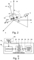
- FIG. 2 schematically illustrates the truck 104 having an associated vehicle coordinate system that includes X, Y and Z axes that can be arbitrarily oriented in the LECS (North-East-Up coordinate system).
- the yaw, pitch and roll rotations are respectively rotations about the Z, Y, and X axes of the vehicle coordinate systems.
- the truck 104 can be driving on a road through a banked curve descending a mountain so that all three of the yaw, pitch and roll rotations occur as the truck 104 travels along its route.
- the system 100 includes a number of satellites 106, 108, 110 including a first satellite 106, a second satellite 108 and a third satellite 110.
- the satellites 106, 108, 110 can, in general, include satellites that are in geostationary orbit and hence fixed in the ECCS and satellites that are not in geostationary orbit and hence not fixed in the ECCS.
- the truck 104 is equipped with a phased array antenna 112 that can be configured to produce high gain patterns centered at any one of a set of directions.
- the phased array antenna 112 is used to communicate with one of the satellites 106, 108, 110 it is beneficial to configure the phase array antenna 112 such that the high gain direction is as close as possible to the direction of the satellite. A benefit of doing so is to increase the link budget and allow for higher data rate communications at a given energy per information symbol.
- the movement of the satellites 106, 108, 110, movement of the truck 104 and the yaw, pitch and roll of the truck 104 tends to quickly render any previously established pointing direction obsolete.
- FIG. 3 is a block diagram of a radio system 300 comprising a satellite radio 302 coupled to the phased array antenna 112 according to an embodiment of the invention.
- the phased array antenna 112 includes a controller 306 coupled to a digital phase shifter array 308 which is coupled to antenna element array 310.
- the satellite radio 302 is coupled to the controller 306 of the phased array antenna 112 through a control bus 312. An indication of the strength of a received signal can be coupled from the satellite radio 302 to the controller 306 through the control bus 312. Alternatively, a subsystem for measuring received signal strength is incorporated in the phased array antenna 112 itself.
- the satellite radio 302 is also coupled to an input/output port 314 of the digital phase shifter array 308 through a communication signal link 316.
- the digital phase shifter array 308 is coupled through a set of N (where N>1) antenna element channels 318 to the antenna element array 310.
- Each of the antenna element channels 318 serves one antenna element (see FIG. 4 ) of the antenna element array 310.
- the digital phase shifter array 308 applies a requisite phase shift between the input/output port 314 and each of the antenna element channels 318 in order to steer the peak gain of the phased array antenna 112 in one of a set of directions.
- the controller 306 can monitor the strength of the received signal through information received via the control bus 312 while trying at least a subset of the set of the possible directions.
- the controller can "search" for the best direction, i.e., the direction in which the peak gain direction is closest to the direction from which signal from one of the satellites 106, 108, 110 is received.
- the controller blindly running through each direction will in many cases be ineffective because the amount of time required to check a given direction compared to the shorter time scale characterizing the changes in orientation of the truck 104 (or other vehicle or object).
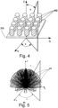
- FIG. 4 is a perspective view of the antenna element array 310 of the phased array antenna 112 according to an embodiment of the invention.
- the antenna element array 310 is an array of Quadrifilar Helical Antenna (QHA) elements 402 (a limited number of which are labeled to avoid crowding the drawing).
- QHA Quadrifilar Helical Antenna
- another type of element such as for example a patch antenna element, dipole, or slot can be used.
- the antenna element array 310 is a four by four square array of QHA elements 402.
- a different number and/or a different pattern (i.e., non-square array) of elements may be used. Examples of QHA elements that may be used are disclosed in co-pending patent application ser. No.
- FIG. 4 shows a set of coordinate axes and a polar angle ⁇ and an azimuth angle ⁇ superimposed on the drawing.
- the polar angle ⁇ and the azimuth angle ⁇ can be used to describe the direction of maximum gain for a given configuration of the phased array antenna 112.
- FIG. 5 is a spherical coordinate system graph 500 schematically representing a set of possible gain patterns 502 (a limited number of which are labeled to avoid crowding the drawing) that can be produced with a phased array antenna, with each gain pattern centered on a particular azimuth ⁇ and polar angle O.
- the gain patterns 502 are represented schematically, and in practice the shape of the gain patterns 502 may be different from what is depicted in FIG. 5 .
- the same set of X, Y and Z coordinate axes presented in FIG. 4 establish the ( ⁇ , ⁇ ) domain of the spherical graph 500 shown in FIG. 5 .
- the X, Y, Z axes of the coordinate system of the phased array antenna 112 either correspond to, or a have a fixed orientation with respect to the X, Y, Z axes of the vehicle coordinate system shown in FIG. 2 .
- a yaw rotation of the vehicle will call for change in the azimuth of the antenna pointing direction
- pitch and roll rotations of the vehicle will call for a change in azimuth and/or polar angle of the antenna pointing direction.
- FIG. 6 is a graph 600 including a schematic illustration of a 2-D cut through a set of adjacent gain patterns that can be produced with a phased array antenna (e.g., 112) according to an embodiment of the invention. Actual gain patterns may differ in shape from what is shown in FIG. 6 .
- the 2-D cut represented in FIG. 6 corresponds to a cut at constant azimuth angle ⁇ with the polar angle ⁇ varying from 0 to ⁇ /2. (However a qualitatively similar plot would be obtained taking a cut at constant polar angle ⁇ with the azimuth angle ⁇ varying or taking a cut through some arbitrary contour in the 2-D angle space, although in the latter case the peaks might vary substantially).
- the graph 600 includes a vertical line 602 at the polar angle value of 0.7 radians.
- phased array antenna 112 can have its direction of maximum gain set to one a certain finite set of directions each of which is described by an azimuth angle ⁇ and a polar angle ⁇ .
- the polar angle can be adjusted to multiples of ⁇ /6 radians (30°). (in practice the achievable polar angles may not be equally spaced.)
- a first gain pattern 604 with its peak at ⁇ /2 radians is closest to the polar coordinate (0.7 radians) of the satellite, and therefore produces the highest gain indicated by an upper dot 606 on the vertical line 602.
- the controller 306 (or other controller in a system) will perform a "local search" around an estimated pointing angle (gain pattern) for a gain pattern that in fact produces the highest gain. For example if the first gain pattern 604 were estimated (by other subsystems to be described hereinbelow) to be the gain pattern that would maximize gain, a 1-D version of a local search could check the gain for the first gain pattern 604 and the two gain patterns adjacent to it which are the second gain pattern 608 and the third gain pattern 612. Through such a local search the controller 306 could determine which gain pattern actually produces the highest gain (highest dot on vertical line 602). The estimate made prior to the local search may be correct or it may be in error (e.g., off by one or more steps in angle).
- a 2-D local search is performed around an estimated pointing angle. For example we can identify an estimated best pointing angle as ( ⁇ i , ⁇ k ) where the index i identifies an i th polar angle to which the phased array antenna 112 can be steered and the index k identifies a k th azimuth angle to which the phased array antenna 112 can be steered, and there is a monotonic relation between the index k and the azimuth angle and there is a monotonic relation between the index I and the polar angle.
- a local search can initially check all of the following pointing angles: ( ⁇ i , ⁇ k ) itself and all neighboring angles: ( ⁇ i+1 , ⁇ k ), ( ⁇ i-1 , ⁇ k ), ( ⁇ i , ⁇ k+1 ), ( ⁇ i , ⁇ k-1 ), ( ⁇ i+1 , ⁇ k+1 ), ( ⁇ i-1, ⁇ k-1 ), ( ⁇ i+1 , ⁇ k-1 ), ( ⁇ i-1 , ⁇ k+1 ).
- the initial local search finds that one of the neighboring angles does in fact produce higher gain initially estimated pointing angle ( ⁇ i , ⁇ k ) a further search of angles adjacent to the pointing angle that produced the largest gain (but excluding angles already checked) can be performed.
- the local search can initially check just two angles in addition to estimated best pointing angle as ( ⁇ i , ⁇ k ). One of the angles will differ in respect to the azimuth angle ⁇ and the second of the angles will differ in respect to the polar angle ⁇ . From the gain values attained with these three directions, a discrete gradient estimate can be computed and then a fourth angle that is in the direction of the direction of the gradient can be checked, and the local search can proceed to follow the locally computed gradient.
- FIG. 7 is a block diagram of a system 700 for maintaining an antenna (e.g., phased array antenna 112) pointed at a second device (e.g., one of the three satellites 106, 108, 110) with which communications are conducted according to an embodiment of the invention.
- the system 700 includes inertial navigation sensors 702 which include a gyroscope set 704 and optionally includes accelerometers 705 which can provide additional orientation information by measuring the direction of gravity.
- the gyroscope set 704 suitably includes three gyroscopes that indicate rotation rates about three mutually orthogonal axes which, by way of non-limiting example, may be the yaw, pitch and roll axes identified in FIG. 2 .
- Outputs of the gyroscope set 704 are coupled to inputs of a Kalman filter 706 tracking the maximum gain antenna pointing direction.
- the Kalman filter 706 evolves a best estimate of the maximum gain pointing angle forward in time based on readings of the rate of rotation of the truck 104 (or other vehicle or object) that are output by the gyroscope set 704.
- the controller 306 is also coupled to the Kalman filter 706.
- the result of the "local search" described above which is also an estimate of the maximum gain antenna pointing direction and that is found by the controller 306 is output by the controller 306 and is input into the Kalman filter 706 as a sensor reading of the maximum gain antenna pointing direction.
- the Kalman filter 706 produces a new estimate for each new time step of a series of time steps based, in part, on the result of the local search and based, in part, on adjustments of a previous estimate based on the gyroscope readings.
- the rates of rotation of the truck 104 (or other vehicle or object) read from the gyroscope set 704 can be used to predict how the azimuth ⁇ and elevation angle ⁇ of the maximum gain pattern, which approximately corresponds to the direction to the second terminal (e.g., satellite 106, 108, 110) will change with each time increment.
- the local search provides a second piece of information concerning the direction of the gain pattern that exhibits maximum gain.
- the Kalman filter 706 can continue to update antenna pointing direction so that when the truck passes the obstruction, the satellite radio 302 and phased array antenna 302 can begin to try to reacquire the satellite signal and the phased array antenna 112 will be more likely to be pointed in the correct direction or close to the correct direction, even if the orientation of the truck 104 has changed (e.g., because the truck turned a corner).
- FIG. 8 is a flowchart 800 of a method of setting and maintaining an antenna (e.g., 112) pointed at a second device (e.g., satellite) with which communications are conducted according to an embodiment of the invention.
- an initial global search for a satellite or other second terminal communication device
- the global search can start a random or predetermined angle and search for the antenna pointing direction that maximizes gain.
- communications with the second device e.g., satellite
- the global search will entail receiving signals from the second device, and can include decoding those signals.
- the Kalman filter 706 is initialized with the azimuth ⁇ and polar ⁇ corresponding to the antenna pointing direction that was found in block 802.
- the rotation rates are read from the gyroscope set 704 and in block 810 the rotation rates are input into the Kalman filter.
- the direction of gravity sensed by the accelerometers is also read and input into the Kalman filter as an additional sensor reading related to orientation.
- the Kalman filter is run in order to predict new values of the azimuth ⁇ and polar ⁇ for the signal second terminal (e.g., satellite 106, 108, 110).
- the signal second terminal e.g., satellite 106, 108, 110.
- phased array antenna 112 is pointed in the direction predicted by the Kalman filter in block 812.
- a local search is performed to check if the new pointing angle or an adjacent pointing angle yields the maximum gain.
- the local search has been described hereinabove.
- azimuth and polar angles that were found in the local search that is the azimuth ⁇ and polar ⁇ angles describing the antenna pointing direction that resulted in maximum gain are input into the Kalman filter as sensor readings of the angles (e.g., satellite).
- the local search that is performed in block 816 takes longer than an interval at which the inertial navigation sensors 702 update their readings.
- the system 700 can continue to update the antenna pointing direction based on estimates that are produced by the Kalman filter 706 as it continues to process new information from the inertial navigation sensors 702, and then, at intervals, when new AOA information is available from the local search the Kalman filter can incorporate that information.
- This alternative is signified by the dashed line connecting blocks 814 and 808 in FIG. 8 .
- FIG. 9 is a block diagram of a system 900 for maintaining a phased array antenna pointed at a second communication terminal (e.g., satellite, 106, 108, 110) and maintaining orientation information for a first apparatus (e.g., truck 104) that includes the phased array antenna according to an embodiment of the invention.
- the system is suitable for mounting on the truck 104 or other moving vehicle or object.
- the system 900 includes a GPS antenna 902 coupled to a GPS receiver 904.
- the GPS receiver 904 is coupled to a Kalman filter 906 that is tracking the location, velocity, acceleration, orientation and angular velocity of the truck 104 (or other moving vehicle or object).
- the GPS receiver 904 provides location and velocity estimates to the Kalman filter 906.
- the gyroscope set 704 is also used in the system 900.
- the gyroscope set 704 provides angular velocity information (in three components) to the Kalman filter 906.
- the system 900 also includes a 3-axis accelerometer 908 that is coupled to the Kalman filter 906 and provides acceleration information (in three components) to the Kalman filter 906.
- An optional electronic compass 910 and stored earth magnetic declination map 912 are provided.
- a location estimate output by the Kalman filter 906 (but which may initially be obtained directly from the GPS receiver 904) provides location information to the earth magnetic declination map 912.
- the local magnetic declination output by the earth magnetic declination map 912 for the current location and a reading of the electronic compass are input to a second orientation computer 914 (the first will be described below), which computes an orientation estimate for the truck 104 (or other moving vehicle or object), and this orientation estimate is input into the Kalman filter 906.
- Optional vehicle control input sensors 916 such as sensors on the steering, accelerator and brake of the truck 104 (or analogous parts of another vehicle or object) are also input into the Kalman filter 906.
- a stored model of position of a satellite 106, 108, 110 (or more generally a second communication terminal) as a function of time 918, (e.g., satellite ephemeris) outputs a satellite location 920 at a current time.
- the stored model of satellite location as a function of time is coupled to the GPS receiver from which the current time is received.
- the current location of the truck 104 (or other moving vehicle or object) in combination with the current location of the satellite 106, 108, 110 can be combined to deduce what the polar and azimuth angles of the satellite, and hence the Angle of Arrival (AOA calc ) are in the Local Earth Coordinate System (LECS) which is described above with reference to FIGs. 1 and 2 .
- the direction of gravity in the LECS is in the negative "Up" axis direction, i.e., straight down.
- An estimate of the actual Angle of Arrival (AOA meas ) 922 of the signal from the satellite is provided by the local search conducted by the controller 306 of the phased array antenna 112 as described above.
- a measurement of the local gravity vector is obtained (e.g., by low pass filtering) from the accelerometer 908.
- the first orientation computer 924 is coupled to the 3-axis accelerometer 908, the Kalman filter 906, the phased array antenna 112, and the stored model of satellite location as a function of time.
- the first orientation computer 924 receives: the AOA estimate produced by local search 922 from the phased array antenna 122; an estimate of the gravity direction from the 3-axis accelerometer 908; the satellite location 920 from the stored model of satellite position as a function of time 918; and an estimate of the current location from the Kalman filter 906 (although initially or alternatively the current location estimate may be received from the GPS receiver 904 directly).
- the orientation of the vehicle coordinate system in the LECS can be determined. This determination is done by the first orientation computer 924.
- the system 900 also includes an antenna pointing direction computer 926.
- the antenna pointing direction computer is coupled to the Kalman filter 906, and the stored model of satellite location as a function of time 918.
- the antenna pointing direction computer 926 receives current estimates of the location and orientation of the truck 104 (or other moving vehicle or object) from the Kalman filter 906; and receives the satellite location 920 from the stored model of satellite location as a function of time 918.
- the antenna pointing direction computer 926 Based on the current estimate of the location truck (or other moving vehicle or object) that is provided by the Kalman filter 906, and based on the satellite location 920, the antenna pointing direction computer 926 computes the correct antenna pointing direction in the LECS (see FIG. 2 ), and then subsequently translates the correct pointing direction into the vehicle coordinate system (see FIG. 2 ) based on the orientation estimate for the truck (or other moving vehicle or object) maintained by the Kalman filter 906.
- the Kalman filter 906 aggregates various sources of information on the orientation, including the information from the first orientation computer 924, information from the second orientation computer 914, information from the gyroscope set 704 and accelerometers 908.
- the first orientation computer 924 uses the maximum gain (AOA) information received from the phased array antenna 112.
- AOA maximum gain
- a least squares estimator is used as an orientation information aggregator. All of the blocks 112, 302, 704, 902, 904, 906, 908, 922 that feed into the first orientation computer 924 along with the first orientation computer itself can be considered a first subsystem that determines one orientation estimate.
- the second orientation computer 914 and the blocks which feed into it 910, 912 can be considered a second subsystem that determines another orientation estimate.
- the velocity information obtained from the GPS receiver can be used as yet another orientation estimate (although the information is not complete in that the roll orientation is not necessarily determined by the velocity).
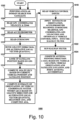
- FIG. 10 is a flowchart 1000 of a method of maintaining an antenna pointed at a second device (e.g., satellite) and for maintaining orientation information for an apparatus that includes the antenna according to an embodiment of the invention.
- an antenna e.g., 112
- the search can be a global search described above, which can for example cover an entire discretized 2 ⁇ steradian hemisphere.
- the search that is executed can be a local search as described above.
- a current location, velocity of the truck 104 (or other moving vehicle or object) and the current time provided by a GPS receiver (e.g., 904) are read.
- an accelerometer's (e.g., 3 axis accelerometer 908) output is read and in block 1008 a gyroscope's (e.g., 704) output is read.
- a gyroscope's e.g., 704
- the direction or gravity is sensed.
- the direction of another know local vector quantity is sensed.
- An example of another known local vector quantity is the earth's magnetic field, which may, for example be known based on the known earth magnetic declination map 912.
- Another example of a known local vector quantity is the direction to a known celestial object which can be sensed optically.
- the AOA of the signal from the satellite is computed in the LECS based on the current vehicle or object (e.g., 104) position and the stored information on the satellite.
- the orientation of the vehicle or object (e.g., 104) within (with respect to) the LECS is calculated based on: the measured AOA (corresponding to the direction of maximum gain) found in block 1002; the AOA calculated in block 1014; measurements of local gravity direction sensed in block 1010 (or direction of alternative local vector quantity as discussed above), and separately available information of the gravity (or alternative local vector quantity) in the LECS. Note that gravity is trivially directly down in the LECS (to a high degree of approximation).
- control inputs e.g., steering, accelerator, brake
- control inputs e.g., steering, accelerator, brake
- a signal conduit e.g., wire or fiber optic
- the orientation estimate generated in block 1016, the accelerometer readings, gyroscope readings, GPS coordinates, GPS velocities and optionally the vehicle control inputs are input into a Kalman filter that is tracking the vehicle position, vehicle velocity and vehicle orientation, and in block 1022 the Kalman filter is run to determine new estimates of the aforementioned parameters.
- a best estimate antenna pointing direction (AOA) for best gain is computed based on: the vehicle location, vehicle orientation, and satellite location and the antenna is pointed accordingly.
- AOA antenna pointing direction
- the Kalman filter 906 can continue to update orientation information for the truck and the orientation information can be used by the antenna pointing direction computer 926 to continue to update the antenna pointing direction so that when the truck emerges from the tunnel, the satellite radio 302 and phased array antenna 302 can begin to try to reacquire the satellite signal and the phased array antenna will be more likely to be pointed in the correct direction or close to the correct direction, even if the orientation of the truck 104 has changed (e.g., because the road within the tunnel is curved).
- embodiments of the invention described herein may be comprised of one or more conventional processors and unique stored program instructions that control the one or more processors to implement, in conjunction with certain non-processor circuits, some, most, or all of the functions of phased array antenna pointing direction control described herein.
- the non-processor circuits may include, but are not limited to, a radio receiver, a radio transmitter, signal drivers, clock circuits, power source circuits, and user input devices. As such, these functions may be interpreted as steps of a method to perform phased array antenna pointing direction control.
Landscapes
- Engineering & Computer Science (AREA)
- Physics & Mathematics (AREA)
- General Physics & Mathematics (AREA)
- Radar, Positioning & Navigation (AREA)
- Remote Sensing (AREA)
- Computer Networks & Wireless Communication (AREA)
- Signal Processing (AREA)
- Variable-Direction Aerials And Aerial Arrays (AREA)
Claims (14)
- Verfahren (1000) zum Halten einer phasengesteuerten Gruppenantenne eines auf einen Satelliten gerichteten erdgebundenen Geräts, wobei das Verfahren Folgendes beinhaltet:(a) Erhalten (1004) einer ersten Position in einem erdzentrierten Koordinatensystem, ECCS, des erdgebundenen Geräts durch Lesen der Koordinaten des globalen Positionierungssystems der phasengesteuerten Gruppenantenne;(b) Nachschlagen (1012) einer zweiten Position im ECCS des Satelliten auf der Basis eines gespeicherten Modells von Satellitenortung als Funktion der Zeit;(c) Bestimmen (1014, 1016) eines Ankunftswinkels, ausgedrückt in einem lokalen Erdkoordinatensystem, LECS, eines Signals von dem Satelliten zu der phasengesteuerten Gruppenantenne auf der Basis i) der in dem genannten Schritt (b) nachgeschlagenen zweiten Position des Satelliten, ii) der in dem genannten Schritt (a) erhaltenen ersten Position der phasengesteuerten Gruppenantenne des erdgebundenen Geräts, und iii) einer Orientierung des erdgebundenen Geräts;(d) Bestimmen (1010) einer geschätzten Richtung in einem Fahrzeugkoordinatensystem, VCS, einer lokalen Vektorgröße an der ersten Position der phasengesteuerten Gruppenantenne des erdgebundenen Geräts, und zum Bestimmen der genannten Orientierung anhand von lokal erfassten Werten an dem erdgebundenen Gerät, ausgewählt aus der Gruppe bestehend aus einer Richtung der Schwerkraft, einer Richtung zu einem Himmelsobjekt und dem Magnetismus der Erde;(e) Durchführen einer lokalen Suche anhand der in dem genannten Schritt (d) bestimmten Ankunftswinkelschätzung im VCS, um einen Ausrichtungswinkel der phasengesteuerten Gruppenantenne mit einem höchsten Gewinn und der genannten Orientierung zu finden;(f) Bestimmen (1024) einer Orientierung der phasengesteuerten Gruppenantenne im LECS auf der Basis des in dem genannten Schritt (c) bestimmten, im LECS ausgedrückten Ankunftswinkels des vom Satelliten kommenden Signals und der geschätzten Richtung der in dem genannten Schritt (d) bestimmten Vektorgröße;(g) Korrigieren der in dem genannten Schritt (f) bestimmten Orientierung der Gruppenantenne in dem LECS anhand des in dem genannten Schritt (c) bestimmten Ankunftswinkels in dem LECS, um eine korrigierte Orientierung der Gruppenantenne in dem LECS zu produzieren;(h) Übersetzen der korrigierten Orientierung der phasengesteuerten Gruppenantenne im LECS in eine Ausrichtungsrichtung der Gruppenantenne innerhalb des VCS; und(i) Ausrichten (1024) der Gruppenantenne auf die Ausrichtungsrichtung innerhalb des VCS.
- Verfahren nach Anspruch 1, wobei die lokale Vektorgröße die Schwerkraft ist.
- Verfahren nach Anspruch 1, wobei die lokale Vektorgröße das Magnetfeld der Erde ist.
- Verfahren nach Anspruch 1, wobei die lokale Vektorgröße eine Richtung zu einem Himmelsobj ekt ist.
- Verfahren nach Anspruch 1, wobei das LECS eine Achse hat, die auf den Erdmittelpunkt oder davon weg ausgerichtet ist.
- Verfahren nach Anspruch 1, wobei der genannte Schritt (e) des Durchführens einer lokalen Suche ferner den Schritt (e1) des Findens des Ausrichtungswinkels der phasengesteuerten Gruppenantenne mit einem höchsten Gewinn, ausgedrückt innerhalb des LECS, beinhaltet.
- Vorrichtung, die Folgendes umfasst:einen Global-Position-Satellite-Empfänger (904), der operativ mit einer phasengesteuerten Gruppenantenne gekoppelt ist, um eine erste Position eines erdgebundenen Geräts zu lesen;einen Satellitenortungscomputer (920) und einen Satellitenortungsmodellspeicher (918) zum Nachschlagen einer zweiten Position eines Satelliten auf der Basis eines gespeicherten Modells von Satellitenortung als Funktion der Zeit;einen Ankunftswinkelcomputer (922), der operativ mit dem Global-Position-Satellite-Empfänger (904) und dem Satellitenortungscomputer (920) gekoppelt ist, um einen Ankunftswinkel eines von dem Satelliten kommenden Signals zu der phasengesteuerten Gruppenantenne auf der Basis von i) der Position des Satelliten von dem Satellitenortungscomputer (920), ii) der Position der Gruppenantenne des erdgebundenen Geräts, ausgedrückt in einem lokalen Erdkoordinatensystem, LECS, von dem Global-Position-Satellite-Empfänger (904) und iii) einer Orientierung des erdgebundenen Geräts zu bestimmen;einen Antennenorientierungscomputer (924), der mit einem Aggregator (906) gekoppelt ist, der mit einem oder mehreren Sensoren des erdgebundenen Geräts gekoppelt ist, um eine geschätzte Richtung einer lokalen Vektorgröße an der ersten Position der phasengesteuerten Gruppenantenne des erdgebundenen Geräts zu bestimmen und um die genannte Orientierung anhand von lokal erfassten Werten von den Sensoren des erdgebundenen Geräts zu bestimmen, ausgewählt aus der Gruppe bestehend aus einer Richtung der Schwerkraft, einer Richtung zu einem Himmelsobjekt und dem Magnetismus der Erde;wobei der Antennenorientierungscomputer (924) operativ mit dem Ankunftswinkelcomputer (922) und dem Aggregator (906) gekoppelt ist, um eine lokale Suche anhand der durch den Ankunftswinkelcomputer bestimmten Ankunftswinkelschätzung in dem Fahrzeugkoordinatensystem, VCS, durchzuführen, um einen Ausrichtungswinkel der phasengesteuerten Gruppenantenne mit einem höchsten Gewinn und der genannten Orientierung zu finden;wobei der Antennenorientierungscomputer (924) operativ mit dem Ankunftswinkelcomputer (922) gekoppelt ist, um eine Orientierung der phasengesteuerten Gruppenantenne in dem LECS auf der Basis des von dem Ankunftswinkelcomputer (922) bestimmten, im LECS ausgedrückten Ankunftswinkels des von dem Satelliten kommenden Signals und der geschätzten Richtung einer von dem Antennenorientierungscomputer (924) bestimmten Vektorgröße zu bestimmen;einen Antennenausrichtungsrichtungs-Computer (926), der operativ mit dem Aggregator (906) und dem Antennenorientierungscomputer (924) und dem Satellitenpositionscomputer (920) gekoppelt ist, um die Orientierung der phasengesteuerten Gruppenantenne in dem LECS, bestimmt von dem genannten Antennenorientierungscomputer (924) anhand des von dem genannten Ankunftswinkelcomputer (922) bestimmten Ankunftswinkels in dem LECS, zu korrigieren, um eine korrigierte Orientierung der Gruppenantenne in dem LECS zu produzieren;wobei der Antennenausrichtungsrichtungs-Computer (926) die korrigierte Orientierung der phasengesteuerten Gruppenantenne im LECS in eine Ausrichtungsrichtung der phasengesteuerten Gruppenantenne innerhalb des VCS übersetzt; undein Satellitenfunkgerät (302), das operativ mit dem Antennenausrichtungsrichtungs-Computer (926) gekoppelt ist, um die phasengesteuerte Gruppenantenne (112) in die Ausrichtungsrichtung innerhalb des VCS auszurichten.
- Vorrichtung nach Anspruch 7, wobei die lokale Vektorgröße die Schwerkraft ist.
- Vorrichtung nach Anspruch 7, wobei die lokale Vektorgröße das Magnetfeld der Erde ist.
- Vorrichtung nach Anspruch 7, wobei die lokale Vektorgröße eine Richtung zu einem Himmelsobjekt ist.
- Vorrichtung nach Anspruch 7, wobei das LECS eine Achse hat, die auf den Erdmittelpunkt oder davon weg ausgerichtet ist.
- Vorrichtung nach Anspruch 7, wobei der Antennenorientierungscomputer (924) die lokale Suche durchführt, um den Ausrichtungswinkel der phasengesteuerten Gruppenantenne mit einem höchsten Gewinn, ausgedrückt innerhalb des LECS, zu finden.
- Vorrichtung nach Anspruch 7, wobei die genannten ein oder mehreren Sensoren des erdgebundenen Geräts ausgewählt sind aus der Gruppe bestehend aus 1) einem Gyroskop (704), 2) einem Beschleunigungsmesser (908), 3) Fahrzeugsensoren (916), 4) einem Kompass (910) und 5) einer erdmagnetischen Deklinationskarte (912), die mit einem anderen Orientierungscomputer (914) verbunden ist.
- Vorrichtung nach Anspruch 7, wobei der genannte Aggregator ausgewählt ist aus einer Gruppe von Aggregatoren bestehend aus einem Kalman-Filter und einem Kleinste-Quadrate-Schätzer.
Applications Claiming Priority (3)
| Application Number | Priority Date | Filing Date | Title |
|---|---|---|---|
| US201461982287P | 2014-04-21 | 2014-04-21 | |
| US14/666,512 US10355351B2 (en) | 2014-04-21 | 2015-03-24 | Antenna array pointing direction estimation and control |
| EP15001152.6A EP2937709A1 (de) | 2014-04-21 | 2015-04-20 | Ausrichtungsschätzung und -steuerung für phasengesteuerte gruppenantenne |
Related Parent Applications (1)
| Application Number | Title | Priority Date | Filing Date |
|---|---|---|---|
| EP15001152.6A Division EP2937709A1 (de) | 2014-04-21 | 2015-04-20 | Ausrichtungsschätzung und -steuerung für phasengesteuerte gruppenantenne |
Publications (3)
| Publication Number | Publication Date |
|---|---|
| EP3499260A1 EP3499260A1 (de) | 2019-06-19 |
| EP3499260C0 EP3499260C0 (de) | 2023-10-04 |
| EP3499260B1 true EP3499260B1 (de) | 2023-10-04 |
Family
ID=52997806
Family Applications (2)
| Application Number | Title | Priority Date | Filing Date |
|---|---|---|---|
| EP15001152.6A Ceased EP2937709A1 (de) | 2014-04-21 | 2015-04-20 | Ausrichtungsschätzung und -steuerung für phasengesteuerte gruppenantenne |
| EP18001004.3A Active EP3499260B1 (de) | 2014-04-21 | 2015-04-20 | Ausrichtungsschätzung und -steuerung für phasengesteuerte gruppenantenne |
Family Applications Before (1)
| Application Number | Title | Priority Date | Filing Date |
|---|---|---|---|
| EP15001152.6A Ceased EP2937709A1 (de) | 2014-04-21 | 2015-04-20 | Ausrichtungsschätzung und -steuerung für phasengesteuerte gruppenantenne |
Country Status (2)
| Country | Link |
|---|---|
| US (1) | US10355351B2 (de) |
| EP (2) | EP2937709A1 (de) |
Families Citing this family (48)
| Publication number | Priority date | Publication date | Assignee | Title |
|---|---|---|---|---|
| EP3414794B1 (de) * | 2016-02-12 | 2020-07-08 | Aeronet Global Communications Labs Dac | Antennenarray für aeronautische kommunikation |
| JP6874127B2 (ja) * | 2016-09-22 | 2021-05-19 | フラウンホッファー−ゲゼルシャフト ツァ フェルダールング デァ アンゲヴァンテン フォアシュンク エー.ファオ | 到来方向推定装置、および到来方向推定方法 |
| US10756428B2 (en) * | 2017-02-13 | 2020-08-25 | General Dynamics Mission Systems, Inc. | Systems and methods for inertial navigation system to RF line-of sight alignment calibration |
| US12475273B2 (en) | 2017-02-22 | 2025-11-18 | Middle Chart, LLC | Agent supportable device for communicating in a direction of interest |
| US12400048B2 (en) | 2020-01-28 | 2025-08-26 | Middle Chart, LLC | Methods and apparatus for two dimensional location based digital content |
| US10902160B2 (en) | 2017-02-22 | 2021-01-26 | Middle Chart, LLC | Cold storage environmental control and product tracking |
| US10740502B2 (en) | 2017-02-22 | 2020-08-11 | Middle Chart, LLC | Method and apparatus for position based query with augmented reality headgear |
| US10872179B2 (en) | 2017-02-22 | 2020-12-22 | Middle Chart, LLC | Method and apparatus for automated site augmentation |
| US10984146B2 (en) | 2017-02-22 | 2021-04-20 | Middle Chart, LLC | Tracking safety conditions of an area |
| US11475177B2 (en) | 2017-02-22 | 2022-10-18 | Middle Chart, LLC | Method and apparatus for improved position and orientation based information display |
| US10740503B1 (en) | 2019-01-17 | 2020-08-11 | Middle Chart, LLC | Spatial self-verifying array of nodes |
| US11900023B2 (en) | 2017-02-22 | 2024-02-13 | Middle Chart, LLC | Agent supportable device for pointing towards an item of interest |
| US10628617B1 (en) * | 2017-02-22 | 2020-04-21 | Middle Chart, LLC | Method and apparatus for wireless determination of position and orientation of a smart device |
| US11900021B2 (en) | 2017-02-22 | 2024-02-13 | Middle Chart, LLC | Provision of digital content via a wearable eye covering |
| US11481527B2 (en) | 2017-02-22 | 2022-10-25 | Middle Chart, LLC | Apparatus for displaying information about an item of equipment in a direction of interest |
| US11625510B2 (en) | 2017-02-22 | 2023-04-11 | Middle Chart, LLC | Method and apparatus for presentation of digital content |
| US12086507B2 (en) | 2017-02-22 | 2024-09-10 | Middle Chart, LLC | Method and apparatus for construction and operation of connected infrastructure |
| US10762251B2 (en) | 2017-02-22 | 2020-09-01 | Middle Chart, LLC | System for conducting a service call with orienteering |
| US10831945B2 (en) | 2017-02-22 | 2020-11-10 | Middle Chart, LLC | Apparatus for operation of connected infrastructure |
| US10949579B2 (en) | 2017-02-22 | 2021-03-16 | Middle Chart, LLC | Method and apparatus for enhanced position and orientation determination |
| US10776529B2 (en) | 2017-02-22 | 2020-09-15 | Middle Chart, LLC | Method and apparatus for enhanced automated wireless orienteering |
| US10620084B2 (en) | 2017-02-22 | 2020-04-14 | Middle Chart, LLC | System for hierarchical actions based upon monitored building conditions |
| US12314638B2 (en) | 2017-02-22 | 2025-05-27 | Middle Chart, LLC | Methods and apparatus for secure persistent location based digital content associated with a three-dimensional reference |
| US10733334B2 (en) | 2017-02-22 | 2020-08-04 | Middle Chart, LLC | Building vital conditions monitoring |
| US11507714B2 (en) | 2020-01-28 | 2022-11-22 | Middle Chart, LLC | Methods and apparatus for secure persistent location based digital content |
| US11468209B2 (en) | 2017-02-22 | 2022-10-11 | Middle Chart, LLC | Method and apparatus for display of digital content associated with a location in a wireless communications area |
| US10824774B2 (en) | 2019-01-17 | 2020-11-03 | Middle Chart, LLC | Methods and apparatus for healthcare facility optimization |
| US11436389B2 (en) | 2017-02-22 | 2022-09-06 | Middle Chart, LLC | Artificial intelligence based exchange of geospatial related digital content |
| US11194938B2 (en) | 2020-01-28 | 2021-12-07 | Middle Chart, LLC | Methods and apparatus for persistent location based digital content |
| US11105883B2 (en) * | 2018-07-25 | 2021-08-31 | Denso International America, Inc. | Circular polarized angle of arrival measurement system |
| CA3114093C (en) | 2018-09-26 | 2024-06-18 | Middle Chart, LLC | Method and apparatus for augmented virtual models and orienteering |
| US11169240B1 (en) | 2018-11-30 | 2021-11-09 | Ball Aerospace & Technologies Corp. | Systems and methods for determining an angle of arrival of a signal at a planar array antenna |
| US11327142B2 (en) | 2019-03-29 | 2022-05-10 | Ball Aerospace & Technologies Corp. | Systems and methods for locating and tracking radio frequency transmitters |
| US11223136B2 (en) * | 2019-05-24 | 2022-01-11 | Denso International America, Inc. | Feed circuit for antenna of angle of arrival measurement system |
| US11909468B2 (en) | 2019-11-12 | 2024-02-20 | Viasat, Inc. | Yaw drift compensation for pointing an antenna |
| US11811489B2 (en) * | 2019-12-30 | 2023-11-07 | Kymeta Corporation | Adaptive and learning motion mitigation for uplink power control |
| US11640486B2 (en) | 2021-03-01 | 2023-05-02 | Middle Chart, LLC | Architectural drawing based exchange of geospatial related digital content |
| DE112021000822T5 (de) * | 2020-01-31 | 2022-11-10 | 7hugs Labs SAS | Sensorfusion für flaches zeigegerät |
| US20210349177A1 (en) * | 2020-05-08 | 2021-11-11 | 7hugs Labs SAS | Low profile pointing device |
| CN114339777B (zh) * | 2020-09-29 | 2023-12-15 | 中国移动通信集团设计院有限公司 | 天线参数优化方法、装置、电子设备及存储介质 |
| EP4352886A1 (de) * | 2021-06-29 | 2024-04-17 | Viasat Inc. | Kommunikationsleistungskartierung für phasengesteuerte gruppenantennen |
| KR20240136954A (ko) * | 2022-01-25 | 2024-09-19 | 크래토스 안테나 솔루션즈 코포레이션 | 노이즈 영향을 받은 신호를 사용한 고도로 경사진 위성 추적 |
| US20240094408A1 (en) * | 2022-09-19 | 2024-03-21 | Kymeta Corporation | Satellite (re-)acquisition and state estimation for mobile flat-panel satellite terminals |
| CN115683043B (zh) * | 2022-10-25 | 2025-07-08 | 中国电子科技集团公司第十研究所 | 基于卡尔曼滤波的箭载相控阵天线箭星指向角计算方法 |
| US12461250B1 (en) * | 2022-11-28 | 2025-11-04 | Amazon Technologies, Inc. | System to determine antenna pointing direction |
| CN119908082A (zh) * | 2023-08-28 | 2025-04-29 | 京东方科技集团股份有限公司 | 卫星跟踪方法、跟踪处理装置及卫星跟踪系统 |
| GB2632181A (en) * | 2024-02-16 | 2025-01-29 | Paradigm Communication Systems Ltd | Improvements relating to satellite communication terminals |
| SE2430548A1 (en) * | 2024-10-31 | 2026-05-01 | Requtech Ab | A satellite receiver with positioning capability and method for using the same |
Family Cites Families (22)
| Publication number | Priority date | Publication date | Assignee | Title |
|---|---|---|---|---|
| JP2579070B2 (ja) * | 1991-03-06 | 1997-02-05 | 日本無線株式会社 | アレイアンテナ及び揺動補償型アンテナ装置 |
| JP3627377B2 (ja) | 1996-05-29 | 2005-03-09 | トヨタ自動車株式会社 | 車載用衛星信号受信装置 |
| US6043778A (en) * | 1997-12-29 | 2000-03-28 | Trimble Navigation Limited | Navigation system and orientation system incorporating solar sighting |
| US6023242A (en) * | 1998-07-07 | 2000-02-08 | Northern Telecom Limited | Establishing communication with a satellite |
| US6016120A (en) * | 1998-12-17 | 2000-01-18 | Trimble Navigation Limited | Method and apparatus for automatically aiming an antenna to a distant location |
| US6463366B2 (en) * | 2000-03-10 | 2002-10-08 | Schafer Corp | Attitude determination and alignment using electro-optical sensors and global navigation satellites |
| US6377211B1 (en) * | 2000-12-13 | 2002-04-23 | Lockheed Martin Corporation | Apparatus and method for pointing a directional device from a moving vehicle toward a spacecraft |
| JP3656575B2 (ja) * | 2001-07-23 | 2005-06-08 | 三菱電機株式会社 | 衛星追尾用アンテナ制御装置 |
| US7911400B2 (en) | 2004-01-07 | 2011-03-22 | Raysat Antenna Systems, L.L.C. | Applications for low profile two-way satellite antenna system |
| US7432868B2 (en) * | 2004-04-26 | 2008-10-07 | Spencer Webb | Portable antenna positioner apparatus and method |
| US8786506B2 (en) * | 2004-04-26 | 2014-07-22 | Antennasys, Inc. | Compact portable antenna positioner system and method |
| TW200537118A (en) * | 2004-05-06 | 2005-11-16 | Mitac Technology Corp | A dynamic direction adjustment control device for a satellite disk antenna on a moving carrier |
| US7522102B2 (en) * | 2004-12-16 | 2009-04-21 | The Boeing Company | Antenna beam steering |
| GB2423191B (en) * | 2005-02-02 | 2007-06-20 | Toshiba Res Europ Ltd | Antenna unit and method of transmission or reception |
| US7009558B1 (en) * | 2005-03-14 | 2006-03-07 | Delphi Technologies, Inc. | Vehicle mounted satellite tracking system |
| US7808429B2 (en) | 2006-12-21 | 2010-10-05 | The Boeing Company | Beam steering control for mobile antennas |
| US7898476B2 (en) * | 2007-01-22 | 2011-03-01 | Raytheon Company | Method and system for controlling the direction of an antenna beam |
| US7956806B2 (en) * | 2009-06-15 | 2011-06-07 | Northrop Grumman Space And Mission Systems Corp. | Tracking arrangement for a communications system on a mobile platform |
| US8665174B2 (en) * | 2011-01-13 | 2014-03-04 | The Boeing Company | Triangular phased array antenna subarray |
| US9778365B2 (en) * | 2011-08-25 | 2017-10-03 | Bae Systems Information And Electronic Systems Integration Inc. | Single receiver GPS pointing vector sensing |
| CN104488136A (zh) * | 2012-06-01 | 2015-04-01 | 伍比克网络公司 | 自动天线指向和稳定系统以及其方法 |
| CN103022692B (zh) | 2012-11-14 | 2014-09-17 | 广东隆伏通讯设备有限公司 | 一种“动中通”卫星指向、捕获与跟踪方法及其系统 |
-
2015
- 2015-03-24 US US14/666,512 patent/US10355351B2/en active Active
- 2015-04-20 EP EP15001152.6A patent/EP2937709A1/de not_active Ceased
- 2015-04-20 EP EP18001004.3A patent/EP3499260B1/de active Active
Also Published As
| Publication number | Publication date |
|---|---|
| EP3499260C0 (de) | 2023-10-04 |
| EP3499260A1 (de) | 2019-06-19 |
| US20180115062A1 (en) | 2018-04-26 |
| US10355351B2 (en) | 2019-07-16 |
| EP2937709A1 (de) | 2015-10-28 |
Similar Documents
| Publication | Publication Date | Title |
|---|---|---|
| US10355351B2 (en) | Antenna array pointing direction estimation and control | |
| CA2837179C (en) | Determining spatial orientation information of a body from multiple electromagnetic signals | |
| US6016120A (en) | Method and apparatus for automatically aiming an antenna to a distant location | |
| US10192540B2 (en) | Coordinated route distribution systems and methods | |
| CN105792126A (zh) | 使用数据融合技术确定物体到物体的位置 | |
| CN106229680B (zh) | 对运动中的卫星天线进行实时对星的装置的应用方法 | |
| CN106410410A (zh) | 一种具有物理水平平台的vsat天线系统卫星捕获跟踪方法 | |
| CN106291647B (zh) | 导航定位方法及装置 | |
| JP2002158525A (ja) | 衛星追尾用アンテナ制御装置 | |
| CN108181630A (zh) | 一种北斗双天线旋转快速定向方法 | |
| CN105841698A (zh) | 一种无需调零的auv舵角精确实时测量系统 | |
| JP6486234B2 (ja) | 測位装置及び測位方法 | |
| US8487812B1 (en) | Method for self-aligning a beamforming sensor to simplify vehicle installation | |
| CN102313546B (zh) | 基于极化电磁波信息链的运动平台姿态感知方法 | |
| CN105007109B (zh) | 动中通卫星通信系统的自适应组合导航天线波束控制方法 | |
| CN102800966A (zh) | 基于波束成型技术的海上浮标节点间无线远距离通信方法 | |
| CN111337055B (zh) | 一种卫星移动通信天线惯导的标校方法 | |
| CN102981177A (zh) | 基于协同源波达信息的运动平台姿态感知方法 | |
| US20050068228A1 (en) | Systems and methods for implementing vector models for antenna communications | |
| JP4535187B2 (ja) | アンテナ姿勢制御装置 | |
| KR101129255B1 (ko) | 자세 센서를 이용한 gps 안테나용 능동형 짐벌 | |
| CN111912404A (zh) | 飞行设备输出姿态修正系统及方法 | |
| CN120576743A (zh) | 一种基于多天线gnss和ins的高精度组合定姿方法 | |
| CN117607929A (zh) | 一种运载火箭海上回收的高精度定位定向测量方法及其系统 | |
| Sollie et al. | Automatic recovery of fixed-wing unmanned aerial vehicle using Bluetooth angle-of-arrival navigation |
Legal Events
| Date | Code | Title | Description |
|---|---|---|---|
| PUAI | Public reference made under article 153(3) epc to a published international application that has entered the european phase |
Free format text: ORIGINAL CODE: 0009012 |
|
| STAA | Information on the status of an ep patent application or granted ep patent |
Free format text: STATUS: REQUEST FOR EXAMINATION WAS MADE |
|
| 17P | Request for examination filed |
Effective date: 20190121 |
|
| AC | Divisional application: reference to earlier application |
Ref document number: 2937709 Country of ref document: EP Kind code of ref document: P |
|
| AK | Designated contracting states |
Kind code of ref document: A1 Designated state(s): AL AT BE BG CH CY CZ DE DK EE ES FI FR GB GR HR HU IE IS IT LI LT LU LV MC MK MT NL NO PL PT RO RS SE SI SK SM TR |
|
| STAA | Information on the status of an ep patent application or granted ep patent |
Free format text: STATUS: EXAMINATION IS IN PROGRESS |
|
| 17Q | First examination report despatched |
Effective date: 20211221 |
|
| GRAP | Despatch of communication of intention to grant a patent |
Free format text: ORIGINAL CODE: EPIDOSNIGR1 |
|
| STAA | Information on the status of an ep patent application or granted ep patent |
Free format text: STATUS: GRANT OF PATENT IS INTENDED |
|
| INTG | Intention to grant announced |
Effective date: 20230413 |
|
| GRAS | Grant fee paid |
Free format text: ORIGINAL CODE: EPIDOSNIGR3 |
|
| GRAA | (expected) grant |
Free format text: ORIGINAL CODE: 0009210 |
|
| STAA | Information on the status of an ep patent application or granted ep patent |
Free format text: STATUS: THE PATENT HAS BEEN GRANTED |
|
| AC | Divisional application: reference to earlier application |
Ref document number: 2937709 Country of ref document: EP Kind code of ref document: P |
|
| AK | Designated contracting states |
Kind code of ref document: B1 Designated state(s): AL AT BE BG CH CY CZ DE DK EE ES FI FR GB GR HR HU IE IS IT LI LT LU LV MC MK MT NL NO PL PT RO RS SE SI SK SM TR |
|
| REG | Reference to a national code |
Ref country code: GB Ref legal event code: FG4D |
|
| REG | Reference to a national code |
Ref country code: CH Ref legal event code: EP |
|
| REG | Reference to a national code |
Ref country code: IE Ref legal event code: FG4D |
|
| REG | Reference to a national code |
Ref country code: DE Ref legal event code: R096 Ref document number: 602015086001 Country of ref document: DE |
|
| U01 | Request for unitary effect filed |
Effective date: 20231101 |
|
| U07 | Unitary effect registered |
Designated state(s): AT BE BG DE DK EE FI FR IT LT LU LV MT NL PT SE SI Effective date: 20231107 |
|
| PG25 | Lapsed in a contracting state [announced via postgrant information from national office to epo] |
Ref country code: GR Free format text: LAPSE BECAUSE OF FAILURE TO SUBMIT A TRANSLATION OF THE DESCRIPTION OR TO PAY THE FEE WITHIN THE PRESCRIBED TIME-LIMIT Effective date: 20240105 |
|
| PG25 | Lapsed in a contracting state [announced via postgrant information from national office to epo] |
Ref country code: IS Free format text: LAPSE BECAUSE OF FAILURE TO SUBMIT A TRANSLATION OF THE DESCRIPTION OR TO PAY THE FEE WITHIN THE PRESCRIBED TIME-LIMIT Effective date: 20240204 |
|
| PG25 | Lapsed in a contracting state [announced via postgrant information from national office to epo] |
Ref country code: ES Free format text: LAPSE BECAUSE OF FAILURE TO SUBMIT A TRANSLATION OF THE DESCRIPTION OR TO PAY THE FEE WITHIN THE PRESCRIBED TIME-LIMIT Effective date: 20231004 |
|
| PG25 | Lapsed in a contracting state [announced via postgrant information from national office to epo] |
Ref country code: IS Free format text: LAPSE BECAUSE OF FAILURE TO SUBMIT A TRANSLATION OF THE DESCRIPTION OR TO PAY THE FEE WITHIN THE PRESCRIBED TIME-LIMIT Effective date: 20240204 Ref country code: GR Free format text: LAPSE BECAUSE OF FAILURE TO SUBMIT A TRANSLATION OF THE DESCRIPTION OR TO PAY THE FEE WITHIN THE PRESCRIBED TIME-LIMIT Effective date: 20240105 Ref country code: ES Free format text: LAPSE BECAUSE OF FAILURE TO SUBMIT A TRANSLATION OF THE DESCRIPTION OR TO PAY THE FEE WITHIN THE PRESCRIBED TIME-LIMIT Effective date: 20231004 |
|
| PG25 | Lapsed in a contracting state [announced via postgrant information from national office to epo] |
Ref country code: RS Free format text: LAPSE BECAUSE OF FAILURE TO SUBMIT A TRANSLATION OF THE DESCRIPTION OR TO PAY THE FEE WITHIN THE PRESCRIBED TIME-LIMIT Effective date: 20231004 Ref country code: PL Free format text: LAPSE BECAUSE OF FAILURE TO SUBMIT A TRANSLATION OF THE DESCRIPTION OR TO PAY THE FEE WITHIN THE PRESCRIBED TIME-LIMIT Effective date: 20231004 Ref country code: NO Free format text: LAPSE BECAUSE OF FAILURE TO SUBMIT A TRANSLATION OF THE DESCRIPTION OR TO PAY THE FEE WITHIN THE PRESCRIBED TIME-LIMIT Effective date: 20240104 Ref country code: HR Free format text: LAPSE BECAUSE OF FAILURE TO SUBMIT A TRANSLATION OF THE DESCRIPTION OR TO PAY THE FEE WITHIN THE PRESCRIBED TIME-LIMIT Effective date: 20231004 |
|
| U20 | Renewal fee for the european patent with unitary effect paid |
Year of fee payment: 10 Effective date: 20240429 |
|
| REG | Reference to a national code |
Ref country code: DE Ref legal event code: R097 Ref document number: 602015086001 Country of ref document: DE |
|
| PG25 | Lapsed in a contracting state [announced via postgrant information from national office to epo] |
Ref country code: CZ Free format text: LAPSE BECAUSE OF FAILURE TO SUBMIT A TRANSLATION OF THE DESCRIPTION OR TO PAY THE FEE WITHIN THE PRESCRIBED TIME-LIMIT Effective date: 20231004 |
|
| PG25 | Lapsed in a contracting state [announced via postgrant information from national office to epo] |
Ref country code: SK Free format text: LAPSE BECAUSE OF FAILURE TO SUBMIT A TRANSLATION OF THE DESCRIPTION OR TO PAY THE FEE WITHIN THE PRESCRIBED TIME-LIMIT Effective date: 20231004 |
|
| PG25 | Lapsed in a contracting state [announced via postgrant information from national office to epo] |
Ref country code: SM Free format text: LAPSE BECAUSE OF FAILURE TO SUBMIT A TRANSLATION OF THE DESCRIPTION OR TO PAY THE FEE WITHIN THE PRESCRIBED TIME-LIMIT Effective date: 20231004 Ref country code: SK Free format text: LAPSE BECAUSE OF FAILURE TO SUBMIT A TRANSLATION OF THE DESCRIPTION OR TO PAY THE FEE WITHIN THE PRESCRIBED TIME-LIMIT Effective date: 20231004 Ref country code: RO Free format text: LAPSE BECAUSE OF FAILURE TO SUBMIT A TRANSLATION OF THE DESCRIPTION OR TO PAY THE FEE WITHIN THE PRESCRIBED TIME-LIMIT Effective date: 20231004 Ref country code: CZ Free format text: LAPSE BECAUSE OF FAILURE TO SUBMIT A TRANSLATION OF THE DESCRIPTION OR TO PAY THE FEE WITHIN THE PRESCRIBED TIME-LIMIT Effective date: 20231004 |
|
| PLBE | No opposition filed within time limit |
Free format text: ORIGINAL CODE: 0009261 |
|
| STAA | Information on the status of an ep patent application or granted ep patent |
Free format text: STATUS: NO OPPOSITION FILED WITHIN TIME LIMIT |
|
| 26N | No opposition filed |
Effective date: 20240705 |
|
| PG25 | Lapsed in a contracting state [announced via postgrant information from national office to epo] |
Ref country code: MC Free format text: LAPSE BECAUSE OF FAILURE TO SUBMIT A TRANSLATION OF THE DESCRIPTION OR TO PAY THE FEE WITHIN THE PRESCRIBED TIME-LIMIT Effective date: 20231004 |
|
| PG25 | Lapsed in a contracting state [announced via postgrant information from national office to epo] |
Ref country code: MC Free format text: LAPSE BECAUSE OF FAILURE TO SUBMIT A TRANSLATION OF THE DESCRIPTION OR TO PAY THE FEE WITHIN THE PRESCRIBED TIME-LIMIT Effective date: 20231004 |
|
| REG | Reference to a national code |
Ref country code: CH Ref legal event code: PL |
|
| PG25 | Lapsed in a contracting state [announced via postgrant information from national office to epo] |
Ref country code: CH Free format text: LAPSE BECAUSE OF NON-PAYMENT OF DUE FEES Effective date: 20240430 |
|
| PG25 | Lapsed in a contracting state [announced via postgrant information from national office to epo] |
Ref country code: IE Free format text: LAPSE BECAUSE OF NON-PAYMENT OF DUE FEES Effective date: 20240420 |
|
| U21 | Renewal fee for the european patent with unitary effect paid with additional fee |
Year of fee payment: 11 Effective date: 20250527 |
|
| PGFP | Annual fee paid to national office [announced via postgrant information from national office to epo] |
Ref country code: GB Payment date: 20250527 Year of fee payment: 11 |
|
| PG25 | Lapsed in a contracting state [announced via postgrant information from national office to epo] |
Ref country code: CY Free format text: LAPSE BECAUSE OF FAILURE TO SUBMIT A TRANSLATION OF THE DESCRIPTION OR TO PAY THE FEE WITHIN THE PRESCRIBED TIME-LIMIT; INVALID AB INITIO Effective date: 20150420 |
|
| PG25 | Lapsed in a contracting state [announced via postgrant information from national office to epo] |
Ref country code: HU Free format text: LAPSE BECAUSE OF FAILURE TO SUBMIT A TRANSLATION OF THE DESCRIPTION OR TO PAY THE FEE WITHIN THE PRESCRIBED TIME-LIMIT; INVALID AB INITIO Effective date: 20150420 |