EP3499146B1 - Heizvorrichtung mit einer haltevorrichtung zur aufnahme einer steuereinheit - Google Patents
Heizvorrichtung mit einer haltevorrichtung zur aufnahme einer steuereinheit Download PDFInfo
- Publication number
- EP3499146B1 EP3499146B1 EP18211472.8A EP18211472A EP3499146B1 EP 3499146 B1 EP3499146 B1 EP 3499146B1 EP 18211472 A EP18211472 A EP 18211472A EP 3499146 B1 EP3499146 B1 EP 3499146B1
- Authority
- EP
- European Patent Office
- Prior art keywords
- latching element
- heating device
- holding device
- housing structure
- latching
- Prior art date
- Legal status (The legal status is an assumption and is not a legal conclusion. Google has not performed a legal analysis and makes no representation as to the accuracy of the status listed.)
- Active
Links
Images




Classifications
-
- F—MECHANICAL ENGINEERING; LIGHTING; HEATING; WEAPONS; BLASTING
- F24—HEATING; RANGES; VENTILATING
- F24H—FLUID HEATERS, e.g. WATER OR AIR HEATERS, HAVING HEAT-GENERATING MEANS, e.g. HEAT PUMPS, IN GENERAL
- F24H9/00—Details
- F24H9/02—Casings; Cover lids; Ornamental panels
-
- F—MECHANICAL ENGINEERING; LIGHTING; HEATING; WEAPONS; BLASTING
- F24—HEATING; RANGES; VENTILATING
- F24H—FLUID HEATERS, e.g. WATER OR AIR HEATERS, HAVING HEAT-GENERATING MEANS, e.g. HEAT PUMPS, IN GENERAL
- F24H9/00—Details
- F24H9/06—Arrangement of mountings or supports
Definitions
- the present invention relates to a heating device with a holding device for receiving a control unit, the holding device having at least one latching element which is provided for fixing the holding device to a housing structure
- Heating devices which have a holding device for receiving a control unit, the holding device having at least one latching element with which the holding device is fastened to a housing structure of the heating device.
- a heating device according to the preamble of claim 1 is from the patent US2010 / 209086A1 and EP1811244A1 known.
- the present heating device has the advantage that the at least one latching element is arranged interchangeably on the holding device, as a result of which the flexibility of the heating device is increased.
- the holding device has at least one construction for attaching the at least one latching element, as a result of which the at least one latching element can be attached to the holding device in a simple manner.
- the at least one construction for attaching the at least one latching element has a recess corresponding to a snap arm of the at least one latching element, as a result of which the at least one latching element can be fixed to the holding device in a particularly simple manner.
- the at least one latching element is designed to correspond to the construction for attaching the at least one latching element such that the at least one latching element at least essentially encloses the structure for attaching the at least one latching element, as a result of which the at least one latching element is particularly stable on the Holding device can be attached.
- the at least one latching element is designed to correspond to a recess formed on the housing structure for receiving the latching element, whereby a stable latching of the at least one latching element on the housing structure is made possible.
- the at least one latching element has an actuating arm, which is intended to detach the holding device from the housing structure of the heating device when actuated, thereby making it easy to handle.
- the actuating arm of the at least one latching element is preferably designed as a snap hook which is intended to snap into the housing structure, as a result of which a particularly easy latching and at the same time easy release of the latching element is made possible.
- the actuating arm of the at least one latching element has a spacer, which is provided to limit the actuation of the at least one latching element, as a result of which damage to the latching element can be avoided if actuated too strongly.
- the actuating arm has an elevation, in particular a barb-like elevation, at one end, as a result of which detachment from the housing structure can be additionally simplified.
- the actuating arm has an actuation area, in particular at the end, preferably at the elevation, the actuation area having a rib-like structure, as a result of which a haptic feedback about the actuation of the latching element can be given to a user.
- the at least one latching element has at least one projection which engages in the housing structure, as a result of which the stability can be increased further.
- the holding device has at least two latching elements, the at least two latching elements being of identical design. In this way, the fixation of the holding device to the housing structure can be additionally improved, and the production costs can be kept low.
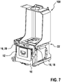
- the holding device 10 for receiving a control unit 22 has two struts 14, between which it holds the control unit 12.
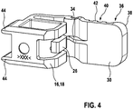
- the holding device 10 is at least one locking element 16, in the case shown a first locking element 18 and a second locking element 20, which is provided to fix the holding device 10 to the housing structure 22 of the heating device 100.
- the holding device 10 is characterized in that the at least one latching element 16 is interchangeably arranged on the holding device 10.
- the heating device 100 is only shown with the housing structure 22 in the figures.
- the holding device 10 has at least one construction 24 for attaching the at least one latching element 16.
- the at least one construction 24 for attaching the at least one latching element 16 has a recess 27 corresponding to a snap arm 26 of the at least one latching element 16.
- the at least locking element 16 is designed to correspond to the structure 24 for attaching the at least one locking element 16 such that the at least one locking element 16 at least substantially encloses the structure 24 for attaching the at least one locking element 16.
- the at least one latching element 16 is designed to correspond to a recess 28 formed on the housing structure 22 for receiving the at least one latching element 16.
- the at least one latching element 16 has an actuating arm 30 which is intended to release the holding device 10 from the housing structure 22 of the heating device 100 when actuated.
- the actuating arm 30 of the at least one latching element 16 is designed as a snap hook 32, which is intended to snap into the housing structure 22.
- the actuating arm 30 of the at least one latching element 16 has a spacer 34, which is provided to limit the actuation of the at least one latching element 16.
- the actuating arm 30 has an, in particular barb-like, elevation 38 at one end 36.
- the actuation arm 30 has an actuation area 40, in particular at the end 36, preferably at the elevation 38, the actuation area 40 having a rib-like structure 42.
- the at least one latching element 16 has at least one projection 44 which engages in the housing structure 22.
- the holding device 10 has two locking elements 16, the two locking elements 16 being of identical design.
Landscapes
- Engineering & Computer Science (AREA)
- Physics & Mathematics (AREA)
- Thermal Sciences (AREA)
- Chemical & Material Sciences (AREA)
- Combustion & Propulsion (AREA)
- Mechanical Engineering (AREA)
- General Engineering & Computer Science (AREA)
- Housings, Intake/Discharge, And Installation Of Fluid Heaters (AREA)
Description
- Die vorliegende Erfindung betrifft eine Heizvorrichtung mit einer Haltevorrichtung zur Aufnahme einer Steuereinheit, wobei die Haltevorrichtung wenigstens ein Rastelement aufweist, welches dazu vorgesehen ist die Haltevorrichtung an einer Gehäusestruktur zu fixieren
- Es sind Heizvorrichtungen bekannt, die eine Haltevorrichtung zur Aufnahme einer Steuereinheit aufweisen, wobei die Haltevorrichtung wenigstens ein Rastelement aufweist mit welchem die Haltevorrichtung an einer Gehäusestruktur der Heizvorrichtung befestigt wird. Eine Heizvorrichtung gemäß dem Oberbegriff des Anspruchs 1 ist aus der Patentschrift
US2010/209086A1 undEP1811244A1 bekannt. - Die vorliegende Heizvorrichtung hat demgegenüber den Vorteil, dass das wenigstens eine Rastelement austauschbar an der Haltevorrichtung angeordnet ist, wodurch die Flexibilität der Heizvorrichtung erhöht wird.
- Durch die in den Unteransprüchen aufgeführten Merkmale sind vorteilhafte Weiterbildungen der Heizvorrichtung nach dem Hauptanspruch möglich. So weist die Haltevorrichtung zumindest eine Konstruktion zum Anbringen des wenigstens einen Rastelements auf, wodurch das wenigstens eine Rastelement auf einfache Weise an die Haltevorrichtung angebracht werden kann.
- Bevorzugt ist es, wenn die zumindest eine Konstruktion zum Anbringen des wenigstens einen Rastelements eine zu einem Schnapparm des wenigstens einen Rastelements korrespondierende Ausnehmung aufweist, wodurch das wenigstens eine Rastelement besonders einfach an die Haltevorrichtung fixiert werden kann.
- Besonders bevorzugt ist es, wenn das wenigstens Rastelement derart korrespondierend zu der Konstruktion zum Anbringen des wenigstens einen Rastelements ausgebildet ist, dass das wenigstens eine Rastelement die Konstruktion zum Anbringen des wenigstens einen Rastelements zumindest im Wesentlichen umschließt, wodurch das wenigstens eine Rastelement besonders stabil an der Haltevorrichtung angebracht werden kann.
- Vorteilhaft ist es, wenn das wenigstens eine Rastelement korrespondierend zu einer an der Gehäusestruktur ausgebildeten Ausnehmung zur Aufnahme des Rastelements ausgebildet ist, wodurch ein stabiles Einrasten des wenigstens einen Rastelements an der Gehäusestruktur ermöglicht wird.
- Erfindungsgemäß ist vorgesehen, dass das wenigstens eine Rastelement einen Betätigungsarm aufweist, welcher dazu vorgesehen ist bei Betätigung die Haltevorrichtung von der Gehäusestruktur der Heizvorrichtung wieder zu lösen, wodurch eine einfache Handhabe ermöglicht wird.
- Vorzugsweise ist der Betätigungsarm des wenigstens einen Rastelements als Schnapphaken ausgebildet, welcher dazu vorgesehen ist in die Gehäusestruktur einzurasten, wodurch ein besonders leichtes einrasten und zugleich ein leichtes Lösen des Rastelements ermöglicht wird.
- Besonders bevorzugt ist es, wenn der Betätigungsarm des wenigstens einen Rastelements einen Abstandshalter aufweist, welcher dazu vorgesehen ist die Betätigung des wenigstens einen Rastelements zu begrenzen, wodurch Beschädigungen des Rastelements bei zu starker Betätigung vermieden werden können.
- Bevorzugt ist es auch, wenn der Betätigungsarm an einem Ende eine, insbesondere wiederhakenartige, Erhebung aufweist, wodurch ein Lösen von der Gehäusestruktur zusätzlich vereinfacht werden kann.
- Auch ist es bevorzugt, wenn der Betätigungsarm einen Betätigungsbereich, insbesondere an dem Ende, vorzugsweise an der Erhebung, aufweist, wobei der Betätigungsbereich eine rippenartige Struktur aufweist, wodurch einem Benutzer ein haptisches Feedback über die Betätigung des Rastelements gegeben werden kann.
- Vorteilhaft ist es auch, wenn das wenigstens eine Rastelement zumindest einen Vorsprung aufweist, der in die Gehäusestruktur eingreift, wodurch die Stabilität zusätzlich erhöht werden kann.
- Besonders vorteilhaft ist es, wenn die Haltevorrichtung zumindest zwei Rastelemente aufweist, wobei die zumindest zwei Rastelemente identisch ausgebildet sind. So kann die Fixierung der Haltevorrichtung an der Gehäusestruktur zusätzlich verbessert werden, wobei die Herstellungskosten gering gehalten werden können.
- In den Zeichnungen ist ein Ausführungsbeispiel der Erfindung schematisch dargestellt und in der nachfolgenden Beschreibung näher erläutert.
- Die Haltevorrichtung 10 zur Aufnahme einer Steuereinheit 22 weist zwei Streben 14 auf, zwischen welchen sie die Steuereinheit 12 aufnimmt.
- Die Haltevorrichtung 10 wist wenigstens ein Rastelement 16, im gezeigten Fall ein erstes Rastelement 18 und ein zweites Rastelement 20, welches dazu vorgesehen ist die Haltevorrichtung 10 an der Gehäusestruktur 22 der Heizvorrichtung 100 zu fixieren. Die Haltevorrichtung 10 zeichnet sich dadurch aus, dass das wenigstens eine Rastelement 16 austauschbar an der Haltevorrichtung 10 angeordnet ist.
- Die Heizvorrichtung 100 ist dabei für eine vereinfachte Darstellung lediglich mit der Gehäusestruktur 22 in den Figuren dargestellt.
- Die Haltevorrichtung 10 weist zumindest eine Konstruktion 24 zum Anbringen des wenigstens einen Rastelements 16 auf.
- Die zumindest eine Konstruktion 24 zum Anbringen des wenigstens einen Rastelements 16 weist eine zu einem Schnapparm 26 des wenigstens einen Rastelements 16 korrespondierende Ausnehmung 27 auf.
- Das wenigstens Rastelement 16 ist derart korrespondierend zu der Konstruktion 24 zum Anbringen des wenigstens einen Rastelements 16 ausgebildet, dass das wenigstens eine Rastelement 16 die Konstruktion 24 zum Anbringen des wenigstens einen Rastelements 16 zumindest im Wesentlichen umschließt.
- Das wenigstens eine Rastelement 16 ist korrespondierend zu einer an der Gehäusestruktur 22 ausgebildeten Ausnehmung 28 zur Aufnahme des wenigstens einen Rastelements 16 ausgebildet.
- Das wenigstens eine Rastelement 16 weist einen Betätigungsarm 30 aufweist, welcher dazu vorgesehen ist bei Betätigung die Haltevorrichtung 10 von der Gehäusestruktur 22 der Heizvorrichtung 100 wieder zu lösen.
- Der Betätigungsarm 30 des wenigstens einen Rastelements 16 ist als Schnapphaken 32 ausgebildet, welcher dazu vorgesehen ist in die Gehäusestruktur 22 einzurasten.
- Der Betätigungsarm 30 des wenigstens einen Rastelements 16 weist einen Abstandshalter 34 auf, welcher dazu vorgesehen ist die Betätigung des wenigstens einen Rastelements 16 zu begrenzen.
- Der Betätigungsarm 30 weist an einem Ende 36 eine, insbesondere wiederhakenartige, Erhebung 38 auf.
- Der Betätigungsarm 30 weist einen Betätigungsbereich 40, insbesondere an dem Ende 36, vorzugsweise an der Erhebung 38, auf, wobei der Betätigungsbereich 40 eine rippenartige Struktur 42 auf.
- Das wenigstens eine Rastelement 16 weist zumindest einen Vorsprung 44 auf, der in die Gehäusestruktur 22 eingreift.
- Wie bereits erwähnt, weist die Haltevorrichtung 10 zwei Rastelemente 16 auf, wobei die zwei Rastelemente 16 identisch ausgebildet sind.
Claims (11)
- Heizvorrichtung (100) mit einer Gehäusestruktur (22) und mit einer Haltevorrichtung (10) zur Aufnahme einer Steuereinheit (12), wobei die Haltevorrichtung (10) wenigstens ein Rastelement (16) aufweist, welches dazu vorgesehen ist die Haltevorrichtung (10) an der Gehäusestruktur (22) der Heizvorrichtung zu fixieren, wobei das wenigstens eine Rastelement (16) austauschbar an der Haltevorrichtung (10) angeordnet ist, dadurch gekennzeichnete, dass das wenigstens eine Rastelement (16) einen Betätigungsarm (30) aufweist, welcher dazu vorgesehen ist bei Betätigung die Haltevorrichtung (10) von der Gehäusestruktur (22) der Heizvorrichtung wieder zu lösen.
- Heizvorrichtung (100) nach einem der vorhergehenden Ansprüche, dadurch gekennzeichnet, dass die Haltevorrichtung (10) zumindest eine Konstruktion (24) zum Anbringen des wenigstens einen Rastelements (16) aufweist.
- Heizvorrichtung (100) nach Anspruch 2, dadurch gekennzeichnet, dass die zumindest eine Konstruktion (24) zum Anbringen des wenigstens einen Rastelements (16) eine zu einem Schnapparm (26) des wenigstens einen Rastelements (16) korrespondierende Ausnehmung (27) aufweist.
- Heizvorrichtung (100) nach einem der Ansprüche 2 oder 3, dadurch gekennzeichnet, dass das wenigstens Rastelement (16) derart korrespondierend zu der Konstruktion (24) zum Anbringen des wenigstens einen Rastelements (16) ausgebildet ist, dass das wenigstens eine Rastelement (16) die Konstruktion (24) zum Anbringen des wenigstens einen Rastelements (16) zumindest im Wesentlichen umschließt.
- Heizvorrichtung (100) nach einem der vorhergehenden Ansprüche, dadurch gekennzeichnet, dass das wenigstens eine Rastelement (16) korrespondierend zu einer an der Gehäusestruktur (22) ausgebildeten Ausnehmung (28) zur Aufnahme des Rastelements (16) ausgebildet ist.
- Heizvorrichtung (100) nach Anspruch 5, dadurch gekennzeichnet, dass der Betätigungsarm (30) des wenigstens einen Rastelements (16) als Schnapphaken (32) ausgebildet ist, welcher dazu vorgesehen ist in die Gehäusestruktur (22) einzurasten.
- Heizvorrichtung (100) nach einem der Ansprüche 5 oder 6, dadurch gekennzeichnet, dass der Betätigungsarm (30) des wenigstens einen Rastelements (16) einen Abstandshalter (34) aufweist, welcher dazu vorgesehen ist die Betätigung des wenigstens einen Rastelements (16) zu begrenzen.
- Heizvorrichtung (100) nach einem der Ansprüche 5 bis 7, dadurch gekennzeichnet, dass der Betätigungsarm (30) an einem Ende (36) eine, insbesondere wiederhakenartige, Erhebung (38) aufweist.
- Heizvorrichtung (100) nach einem der Ansprüche 5 bis 8, dadurch gekennzeichnet, dass der Betätigungsarm (30) einen Betätigungsbereich (40), insbesondere an dem Ende (36), vorzugsweise an der Erhebung (38), aufweist, wobei der Betätigungsbereich (40) eine rippenartige Struktur (42) aufweist.
- Heizvorrichtung (100) nach einem der vorhergehenden Ansprüche, dadurch gekennzeichnet, dass das wenigstens eine Rastelement (16) zumindest einen Vorsprung aufweist, der in die Gehäusestruktur (22) eingreift.
- Heizvorrichtung (100) nach einem der vorhergehenden Ansprüche, dadurch gekennzeichnet, dass die Haltevorrichtung (10) zumindest zwei Rastelemente (16) aufweist, wobei die zumindest zwei Rastelemente (16) identisch ausgebildet sind.
Applications Claiming Priority (1)
| Application Number | Priority Date | Filing Date | Title |
|---|---|---|---|
| DE102017222670.6A DE102017222670A1 (de) | 2017-12-13 | 2017-12-13 | Heizvorrichtung mit einer Haltevorrichtung zur Aufnahme einer Steuereinheit |
Publications (2)
| Publication Number | Publication Date |
|---|---|
| EP3499146A1 EP3499146A1 (de) | 2019-06-19 |
| EP3499146B1 true EP3499146B1 (de) | 2020-07-22 |
Family
ID=64664613
Family Applications (1)
| Application Number | Title | Priority Date | Filing Date |
|---|---|---|---|
| EP18211472.8A Active EP3499146B1 (de) | 2017-12-13 | 2018-12-11 | Heizvorrichtung mit einer haltevorrichtung zur aufnahme einer steuereinheit |
Country Status (2)
| Country | Link |
|---|---|
| EP (1) | EP3499146B1 (de) |
| DE (1) | DE102017222670A1 (de) |
Family Cites Families (7)
| Publication number | Priority date | Publication date | Assignee | Title |
|---|---|---|---|---|
| DE9300450U1 (de) * | 1993-01-15 | 1993-08-12 | Vogel & Noot Wärmetechnik GmbH, Wartberg | Verkleidung für Warmwasserspeicher, -bereiter oder -kessel |
| DE29815355U1 (de) * | 1998-08-27 | 1999-02-11 | Buderus Heiztechnik Gmbh, 35576 Wetzlar | Halter für einen Sensor |
| DE10057943B4 (de) * | 2000-11-22 | 2007-10-11 | Wolf Gmbh | Gastherme oder Gasbrennwerttherme |
| DE202004015442U1 (de) * | 2004-10-05 | 2006-02-09 | J. Eberspächer GmbH & Co. KG | Steuergerät für ein Fahrzeugheizgerät zur Steuerung des Betriebs eines Luftfördergebläses |
| AT503217B1 (de) * | 2006-01-19 | 2007-11-15 | Vaillant Austria Gmbh | Heizgerät mit elektrischen anschlüssen |
| FR2923895B1 (fr) * | 2007-11-20 | 2009-11-20 | Imhotep Creation | Radiateur seche-serviettes a fluide caloporteur equipe d'un dispositif additionnel de chauffage. |
| DE102016204021B4 (de) * | 2016-03-11 | 2023-12-07 | Stiebel Eltron Gmbh & Co. Kg | Haustechnikgerät zum Durchführen einer Aufgabe unter Verwendung elektrischen Stroms |
-
2017
- 2017-12-13 DE DE102017222670.6A patent/DE102017222670A1/de active Pending
-
2018
- 2018-12-11 EP EP18211472.8A patent/EP3499146B1/de active Active
Non-Patent Citations (1)
| Title |
|---|
| None * |
Also Published As
| Publication number | Publication date |
|---|---|
| EP3499146A1 (de) | 2019-06-19 |
| DE102017222670A1 (de) | 2019-06-13 |
Similar Documents
| Publication | Publication Date | Title |
|---|---|---|
| DE102015221874B4 (de) | Gebrauchsmesser | |
| DE202016102955U1 (de) | Multifunktionssäge mit einem Schnellspann-Sägeblatt | |
| EP3499146A1 (de) | Heizvorrichtung mit einer haltevorrichtung zur aufnahme einer steuereinheit | |
| DE202018004940U1 (de) | Schüttel- und/oder Mischgerät | |
| EP3791973A1 (de) | Coilablagevorrichtung | |
| DE102015217405B4 (de) | Wischblattvorrichtung | |
| DE202013105050U1 (de) | Ein Skalpell mit austauschbarer Klinge | |
| DE10107058A1 (de) | Kieferorthopädische Vorrichtung zur Bewegung und/oder Einordnung von Zähnen | |
| DE202008007190U1 (de) | Halter für Touchstifte | |
| DE202013105337U1 (de) | Demontagevorrichtung für Fahrzeugglas | |
| WO2015113961A1 (de) | Anordnung eines zubehörteils auf einem flanschbauteil | |
| DE202016106410U1 (de) | Einsetzhilfe für ein Hinter-dem-Ohr-Hörgerät | |
| DE202007008541U1 (de) | Verschlußkappe für einen hohlen Werkzeughandgriff | |
| DE102017124503B4 (de) | Anschlussvorrichtung zum Anschluss eines Armbandes an ein Gehäuse einer Armbanduhr und Armbanduhr | |
| DE269258C (de) | ||
| EP3018368A2 (de) | Doppelhaken und systeme | |
| WO2019000004A1 (de) | Vorrichtung zur befestigung einer abschlussleiste | |
| EP3354297A1 (de) | Vorrichtung zur halterung einer medizintechnischen komponente | |
| DE10121983B4 (de) | Befestigungselement für die Befestigung von vorzugsweise lösbaren Elementen | |
| DE102010026593A1 (de) | Steuerungseinrichtung | |
| DE102009005814A1 (de) | Abtrennbarer Handgriff | |
| DE428053C (de) | Brennschere mit zwischen die freien Enden der Griffschenkel eingeschalteter Blattfeder | |
| DE102016123815A1 (de) | Werkzeug für Steckverbinder | |
| DE910702C (de) | Drehkondensator, insbesondere fuer Rundfunkgeraete | |
| DE202015104638U1 (de) | Befestigungskonstruktion eines Brillenglases |
Legal Events
| Date | Code | Title | Description |
|---|---|---|---|
| PUAI | Public reference made under article 153(3) epc to a published international application that has entered the european phase |
Free format text: ORIGINAL CODE: 0009012 |
|
| STAA | Information on the status of an ep patent application or granted ep patent |
Free format text: STATUS: THE APPLICATION HAS BEEN PUBLISHED |
|
| AK | Designated contracting states |
Kind code of ref document: A1 Designated state(s): AL AT BE BG CH CY CZ DE DK EE ES FI FR GB GR HR HU IE IS IT LI LT LU LV MC MK MT NL NO PL PT RO RS SE SI SK SM TR |
|
| AX | Request for extension of the european patent |
Extension state: BA ME |
|
| STAA | Information on the status of an ep patent application or granted ep patent |
Free format text: STATUS: REQUEST FOR EXAMINATION WAS MADE |
|
| 17P | Request for examination filed |
Effective date: 20191219 |
|
| RBV | Designated contracting states (corrected) |
Designated state(s): AL AT BE BG CH CY CZ DE DK EE ES FI FR GB GR HR HU IE IS IT LI LT LU LV MC MK MT NL NO PL PT RO RS SE SI SK SM TR |
|
| GRAP | Despatch of communication of intention to grant a patent |
Free format text: ORIGINAL CODE: EPIDOSNIGR1 |
|
| STAA | Information on the status of an ep patent application or granted ep patent |
Free format text: STATUS: GRANT OF PATENT IS INTENDED |
|
| INTG | Intention to grant announced |
Effective date: 20200313 |
|
| RAP1 | Party data changed (applicant data changed or rights of an application transferred) |
Owner name: ROBERT BOSCH GMBH |
|
| GRAS | Grant fee paid |
Free format text: ORIGINAL CODE: EPIDOSNIGR3 |
|
| GRAA | (expected) grant |
Free format text: ORIGINAL CODE: 0009210 |
|
| STAA | Information on the status of an ep patent application or granted ep patent |
Free format text: STATUS: THE PATENT HAS BEEN GRANTED |
|
| AK | Designated contracting states |
Kind code of ref document: B1 Designated state(s): AL AT BE BG CH CY CZ DE DK EE ES FI FR GB GR HR HU IE IS IT LI LT LU LV MC MK MT NL NO PL PT RO RS SE SI SK SM TR |
|
| REG | Reference to a national code |
Ref country code: GB Ref legal event code: FG4D Free format text: NOT ENGLISH |
|
| REG | Reference to a national code |
Ref country code: CH Ref legal event code: EP |
|
| REG | Reference to a national code |
Ref country code: DE Ref legal event code: R096 Ref document number: 502018001953 Country of ref document: DE |
|
| REG | Reference to a national code |
Ref country code: AT Ref legal event code: REF Ref document number: 1293765 Country of ref document: AT Kind code of ref document: T Effective date: 20200815 |
|
| REG | Reference to a national code |
Ref country code: IE Ref legal event code: FG4D Free format text: LANGUAGE OF EP DOCUMENT: GERMAN |
|
| REG | Reference to a national code |
Ref country code: LT Ref legal event code: MG4D |
|
| PG25 | Lapsed in a contracting state [announced via postgrant information from national office to epo] |
Ref country code: ES Free format text: LAPSE BECAUSE OF FAILURE TO SUBMIT A TRANSLATION OF THE DESCRIPTION OR TO PAY THE FEE WITHIN THE PRESCRIBED TIME-LIMIT Effective date: 20200722 Ref country code: LT Free format text: LAPSE BECAUSE OF FAILURE TO SUBMIT A TRANSLATION OF THE DESCRIPTION OR TO PAY THE FEE WITHIN THE PRESCRIBED TIME-LIMIT Effective date: 20200722 Ref country code: HR Free format text: LAPSE BECAUSE OF FAILURE TO SUBMIT A TRANSLATION OF THE DESCRIPTION OR TO PAY THE FEE WITHIN THE PRESCRIBED TIME-LIMIT Effective date: 20200722 Ref country code: SE Free format text: LAPSE BECAUSE OF FAILURE TO SUBMIT A TRANSLATION OF THE DESCRIPTION OR TO PAY THE FEE WITHIN THE PRESCRIBED TIME-LIMIT Effective date: 20200722 Ref country code: PT Free format text: LAPSE BECAUSE OF FAILURE TO SUBMIT A TRANSLATION OF THE DESCRIPTION OR TO PAY THE FEE WITHIN THE PRESCRIBED TIME-LIMIT Effective date: 20201123 Ref country code: GR Free format text: LAPSE BECAUSE OF FAILURE TO SUBMIT A TRANSLATION OF THE DESCRIPTION OR TO PAY THE FEE WITHIN THE PRESCRIBED TIME-LIMIT Effective date: 20201023 Ref country code: BG Free format text: LAPSE BECAUSE OF FAILURE TO SUBMIT A TRANSLATION OF THE DESCRIPTION OR TO PAY THE FEE WITHIN THE PRESCRIBED TIME-LIMIT Effective date: 20201022 Ref country code: NO Free format text: LAPSE BECAUSE OF FAILURE TO SUBMIT A TRANSLATION OF THE DESCRIPTION OR TO PAY THE FEE WITHIN THE PRESCRIBED TIME-LIMIT Effective date: 20201022 Ref country code: FI Free format text: LAPSE BECAUSE OF FAILURE TO SUBMIT A TRANSLATION OF THE DESCRIPTION OR TO PAY THE FEE WITHIN THE PRESCRIBED TIME-LIMIT Effective date: 20200722 |
|
| PG25 | Lapsed in a contracting state [announced via postgrant information from national office to epo] |
Ref country code: IS Free format text: LAPSE BECAUSE OF FAILURE TO SUBMIT A TRANSLATION OF THE DESCRIPTION OR TO PAY THE FEE WITHIN THE PRESCRIBED TIME-LIMIT Effective date: 20201122 Ref country code: RS Free format text: LAPSE BECAUSE OF FAILURE TO SUBMIT A TRANSLATION OF THE DESCRIPTION OR TO PAY THE FEE WITHIN THE PRESCRIBED TIME-LIMIT Effective date: 20200722 Ref country code: LV Free format text: LAPSE BECAUSE OF FAILURE TO SUBMIT A TRANSLATION OF THE DESCRIPTION OR TO PAY THE FEE WITHIN THE PRESCRIBED TIME-LIMIT Effective date: 20200722 Ref country code: PL Free format text: LAPSE BECAUSE OF FAILURE TO SUBMIT A TRANSLATION OF THE DESCRIPTION OR TO PAY THE FEE WITHIN THE PRESCRIBED TIME-LIMIT Effective date: 20200722 |
|
| PG25 | Lapsed in a contracting state [announced via postgrant information from national office to epo] |
Ref country code: NL Free format text: LAPSE BECAUSE OF FAILURE TO SUBMIT A TRANSLATION OF THE DESCRIPTION OR TO PAY THE FEE WITHIN THE PRESCRIBED TIME-LIMIT Effective date: 20200722 |
|
| REG | Reference to a national code |
Ref country code: DE Ref legal event code: R097 Ref document number: 502018001953 Country of ref document: DE |
|
| PG25 | Lapsed in a contracting state [announced via postgrant information from national office to epo] |
Ref country code: CZ Free format text: LAPSE BECAUSE OF FAILURE TO SUBMIT A TRANSLATION OF THE DESCRIPTION OR TO PAY THE FEE WITHIN THE PRESCRIBED TIME-LIMIT Effective date: 20200722 Ref country code: DK Free format text: LAPSE BECAUSE OF FAILURE TO SUBMIT A TRANSLATION OF THE DESCRIPTION OR TO PAY THE FEE WITHIN THE PRESCRIBED TIME-LIMIT Effective date: 20200722 Ref country code: RO Free format text: LAPSE BECAUSE OF FAILURE TO SUBMIT A TRANSLATION OF THE DESCRIPTION OR TO PAY THE FEE WITHIN THE PRESCRIBED TIME-LIMIT Effective date: 20200722 Ref country code: EE Free format text: LAPSE BECAUSE OF FAILURE TO SUBMIT A TRANSLATION OF THE DESCRIPTION OR TO PAY THE FEE WITHIN THE PRESCRIBED TIME-LIMIT Effective date: 20200722 Ref country code: IT Free format text: LAPSE BECAUSE OF FAILURE TO SUBMIT A TRANSLATION OF THE DESCRIPTION OR TO PAY THE FEE WITHIN THE PRESCRIBED TIME-LIMIT Effective date: 20200722 Ref country code: SM Free format text: LAPSE BECAUSE OF FAILURE TO SUBMIT A TRANSLATION OF THE DESCRIPTION OR TO PAY THE FEE WITHIN THE PRESCRIBED TIME-LIMIT Effective date: 20200722 |
|
| PLBE | No opposition filed within time limit |
Free format text: ORIGINAL CODE: 0009261 |
|
| STAA | Information on the status of an ep patent application or granted ep patent |
Free format text: STATUS: NO OPPOSITION FILED WITHIN TIME LIMIT |
|
| PG25 | Lapsed in a contracting state [announced via postgrant information from national office to epo] |
Ref country code: AL Free format text: LAPSE BECAUSE OF FAILURE TO SUBMIT A TRANSLATION OF THE DESCRIPTION OR TO PAY THE FEE WITHIN THE PRESCRIBED TIME-LIMIT Effective date: 20200722 |
|
| 26N | No opposition filed |
Effective date: 20210423 |
|
| PG25 | Lapsed in a contracting state [announced via postgrant information from national office to epo] |
Ref country code: SK Free format text: LAPSE BECAUSE OF FAILURE TO SUBMIT A TRANSLATION OF THE DESCRIPTION OR TO PAY THE FEE WITHIN THE PRESCRIBED TIME-LIMIT Effective date: 20200722 |
|
| PG25 | Lapsed in a contracting state [announced via postgrant information from national office to epo] |
Ref country code: MC Free format text: LAPSE BECAUSE OF FAILURE TO SUBMIT A TRANSLATION OF THE DESCRIPTION OR TO PAY THE FEE WITHIN THE PRESCRIBED TIME-LIMIT Effective date: 20200722 Ref country code: SI Free format text: LAPSE BECAUSE OF FAILURE TO SUBMIT A TRANSLATION OF THE DESCRIPTION OR TO PAY THE FEE WITHIN THE PRESCRIBED TIME-LIMIT Effective date: 20200722 |
|
| REG | Reference to a national code |
Ref country code: BE Ref legal event code: MM Effective date: 20201231 |
|
| REG | Reference to a national code |
Ref country code: NL Ref legal event code: MP Effective date: 20200722 |
|
| PG25 | Lapsed in a contracting state [announced via postgrant information from national office to epo] |
Ref country code: LU Free format text: LAPSE BECAUSE OF NON-PAYMENT OF DUE FEES Effective date: 20201211 Ref country code: IE Free format text: LAPSE BECAUSE OF NON-PAYMENT OF DUE FEES Effective date: 20201211 |
|
| PG25 | Lapsed in a contracting state [announced via postgrant information from national office to epo] |
Ref country code: TR Free format text: LAPSE BECAUSE OF FAILURE TO SUBMIT A TRANSLATION OF THE DESCRIPTION OR TO PAY THE FEE WITHIN THE PRESCRIBED TIME-LIMIT Effective date: 20200722 Ref country code: MT Free format text: LAPSE BECAUSE OF FAILURE TO SUBMIT A TRANSLATION OF THE DESCRIPTION OR TO PAY THE FEE WITHIN THE PRESCRIBED TIME-LIMIT Effective date: 20200722 Ref country code: CY Free format text: LAPSE BECAUSE OF FAILURE TO SUBMIT A TRANSLATION OF THE DESCRIPTION OR TO PAY THE FEE WITHIN THE PRESCRIBED TIME-LIMIT Effective date: 20200722 |
|
| PG25 | Lapsed in a contracting state [announced via postgrant information from national office to epo] |
Ref country code: MK Free format text: LAPSE BECAUSE OF FAILURE TO SUBMIT A TRANSLATION OF THE DESCRIPTION OR TO PAY THE FEE WITHIN THE PRESCRIBED TIME-LIMIT Effective date: 20200722 |
|
| PG25 | Lapsed in a contracting state [announced via postgrant information from national office to epo] |
Ref country code: BE Free format text: LAPSE BECAUSE OF NON-PAYMENT OF DUE FEES Effective date: 20201231 |
|
| REG | Reference to a national code |
Ref country code: CH Ref legal event code: PL |
|
| PG25 | Lapsed in a contracting state [announced via postgrant information from national office to epo] |
Ref country code: LI Free format text: LAPSE BECAUSE OF NON-PAYMENT OF DUE FEES Effective date: 20211231 Ref country code: CH Free format text: LAPSE BECAUSE OF NON-PAYMENT OF DUE FEES Effective date: 20211231 |
|
| REG | Reference to a national code |
Ref country code: AT Ref legal event code: MM01 Ref document number: 1293765 Country of ref document: AT Kind code of ref document: T Effective date: 20231211 |
|
| PG25 | Lapsed in a contracting state [announced via postgrant information from national office to epo] |
Ref country code: AT Free format text: LAPSE BECAUSE OF NON-PAYMENT OF DUE FEES Effective date: 20231211 |
|
| PGFP | Annual fee paid to national office [announced via postgrant information from national office to epo] |
Ref country code: GB Payment date: 20251218 Year of fee payment: 8 |
|
| PGFP | Annual fee paid to national office [announced via postgrant information from national office to epo] |
Ref country code: FR Payment date: 20251218 Year of fee payment: 8 |
|
| PGFP | Annual fee paid to national office [announced via postgrant information from national office to epo] |
Ref country code: DE Payment date: 20260223 Year of fee payment: 8 |
|
| PGFP | Annual fee paid to national office [announced via postgrant information from national office to epo] |
Ref country code: AT Payment date: 20260410 Year of fee payment: 5 |