EP3499088A1 - Getriebe für ein kraftfahrzeug, und verfahren zum betrieb eines solchen getriebes - Google Patents
Getriebe für ein kraftfahrzeug, und verfahren zum betrieb eines solchen getriebes Download PDFInfo
- Publication number
- EP3499088A1 EP3499088A1 EP17207313.2A EP17207313A EP3499088A1 EP 3499088 A1 EP3499088 A1 EP 3499088A1 EP 17207313 A EP17207313 A EP 17207313A EP 3499088 A1 EP3499088 A1 EP 3499088A1
- Authority
- EP
- European Patent Office
- Prior art keywords
- clutch
- input
- transmission
- clutches
- torque
- Prior art date
- Legal status (The legal status is an assumption and is not a legal conclusion. Google has not performed a legal analysis and makes no representation as to the accuracy of the status listed.)
- Granted
Links
- 230000005540 biological transmission Effects 0.000 title claims abstract description 153
- 238000000034 method Methods 0.000 title claims abstract description 26
- 230000006978 adaptation Effects 0.000 claims description 3
- 230000003213 activating effect Effects 0.000 claims 1
- 230000008859 change Effects 0.000 abstract description 8
- 230000015572 biosynthetic process Effects 0.000 description 6
- 230000008569 process Effects 0.000 description 6
- 238000002485 combustion reaction Methods 0.000 description 4
- 238000010586 diagram Methods 0.000 description 4
- 230000001360 synchronised effect Effects 0.000 description 4
- 230000008878 coupling Effects 0.000 description 3
- 238000010168 coupling process Methods 0.000 description 3
- 238000005859 coupling reaction Methods 0.000 description 3
- 230000000694 effects Effects 0.000 description 3
- 230000009467 reduction Effects 0.000 description 3
- 230000001133 acceleration Effects 0.000 description 2
- 238000004891 communication Methods 0.000 description 2
- 238000012937 correction Methods 0.000 description 2
- 230000001419 dependent effect Effects 0.000 description 2
- 238000013461 design Methods 0.000 description 2
- 238000004519 manufacturing process Methods 0.000 description 2
- 238000012360 testing method Methods 0.000 description 2
- 230000004913 activation Effects 0.000 description 1
- 230000008901 benefit Effects 0.000 description 1
- 238000010276 construction Methods 0.000 description 1
- 238000001816 cooling Methods 0.000 description 1
- 230000002123 temporal effect Effects 0.000 description 1
- 238000013519 translation Methods 0.000 description 1
- 238000004804 winding Methods 0.000 description 1
Images


Classifications
-
- F—MECHANICAL ENGINEERING; LIGHTING; HEATING; WEAPONS; BLASTING
- F16—ENGINEERING ELEMENTS AND UNITS; GENERAL MEASURES FOR PRODUCING AND MAINTAINING EFFECTIVE FUNCTIONING OF MACHINES OR INSTALLATIONS; THERMAL INSULATION IN GENERAL
- F16H—GEARING
- F16H3/00—Toothed gearings for conveying rotary motion with variable gear ratio or for reversing rotary motion
- F16H3/006—Toothed gearings for conveying rotary motion with variable gear ratio or for reversing rotary motion power being selectively transmitted by either one of the parallel flow paths
-
- F—MECHANICAL ENGINEERING; LIGHTING; HEATING; WEAPONS; BLASTING
- F16—ENGINEERING ELEMENTS AND UNITS; GENERAL MEASURES FOR PRODUCING AND MAINTAINING EFFECTIVE FUNCTIONING OF MACHINES OR INSTALLATIONS; THERMAL INSULATION IN GENERAL
- F16H—GEARING
- F16H3/00—Toothed gearings for conveying rotary motion with variable gear ratio or for reversing rotary motion
- F16H3/02—Toothed gearings for conveying rotary motion with variable gear ratio or for reversing rotary motion without gears having orbital motion
- F16H3/08—Toothed gearings for conveying rotary motion with variable gear ratio or for reversing rotary motion without gears having orbital motion exclusively or essentially with continuously meshing gears, that can be disengaged from their shafts
- F16H3/12—Toothed gearings for conveying rotary motion with variable gear ratio or for reversing rotary motion without gears having orbital motion exclusively or essentially with continuously meshing gears, that can be disengaged from their shafts with means for synchronisation not incorporated in the clutches
-
- F—MECHANICAL ENGINEERING; LIGHTING; HEATING; WEAPONS; BLASTING
- F16—ENGINEERING ELEMENTS AND UNITS; GENERAL MEASURES FOR PRODUCING AND MAINTAINING EFFECTIVE FUNCTIONING OF MACHINES OR INSTALLATIONS; THERMAL INSULATION IN GENERAL
- F16H—GEARING
- F16H61/00—Control functions within control units of change-speed- or reversing-gearings for conveying rotary motion ; Control of exclusively fluid gearing, friction gearing, gearings with endless flexible members or other particular types of gearing
- F16H61/04—Smoothing ratio shift
- F16H61/0403—Synchronisation before shifting
-
- F—MECHANICAL ENGINEERING; LIGHTING; HEATING; WEAPONS; BLASTING
- F16—ENGINEERING ELEMENTS AND UNITS; GENERAL MEASURES FOR PRODUCING AND MAINTAINING EFFECTIVE FUNCTIONING OF MACHINES OR INSTALLATIONS; THERMAL INSULATION IN GENERAL
- F16H—GEARING
- F16H61/00—Control functions within control units of change-speed- or reversing-gearings for conveying rotary motion ; Control of exclusively fluid gearing, friction gearing, gearings with endless flexible members or other particular types of gearing
- F16H61/68—Control functions within control units of change-speed- or reversing-gearings for conveying rotary motion ; Control of exclusively fluid gearing, friction gearing, gearings with endless flexible members or other particular types of gearing specially adapted for stepped gearings
- F16H61/684—Control functions within control units of change-speed- or reversing-gearings for conveying rotary motion ; Control of exclusively fluid gearing, friction gearing, gearings with endless flexible members or other particular types of gearing specially adapted for stepped gearings without interruption of drive
- F16H61/688—Control functions within control units of change-speed- or reversing-gearings for conveying rotary motion ; Control of exclusively fluid gearing, friction gearing, gearings with endless flexible members or other particular types of gearing specially adapted for stepped gearings without interruption of drive with two inputs, e.g. selection of one of two torque-flow paths by clutches
-
- F—MECHANICAL ENGINEERING; LIGHTING; HEATING; WEAPONS; BLASTING
- F16—ENGINEERING ELEMENTS AND UNITS; GENERAL MEASURES FOR PRODUCING AND MAINTAINING EFFECTIVE FUNCTIONING OF MACHINES OR INSTALLATIONS; THERMAL INSULATION IN GENERAL
- F16H—GEARING
- F16H2200/00—Transmissions for multiple ratios
- F16H2200/003—Transmissions for multiple ratios characterised by the number of forward speeds
- F16H2200/0056—Transmissions for multiple ratios characterised by the number of forward speeds the gear ratios comprising seven forward speeds
-
- F—MECHANICAL ENGINEERING; LIGHTING; HEATING; WEAPONS; BLASTING
- F16—ENGINEERING ELEMENTS AND UNITS; GENERAL MEASURES FOR PRODUCING AND MAINTAINING EFFECTIVE FUNCTIONING OF MACHINES OR INSTALLATIONS; THERMAL INSULATION IN GENERAL
- F16H—GEARING
- F16H2200/00—Transmissions for multiple ratios
- F16H2200/0082—Transmissions for multiple ratios characterised by the number of reverse speeds
- F16H2200/0086—Transmissions for multiple ratios characterised by the number of reverse speeds the gear ratios comprising two reverse speeds
Definitions
- the invention relates to a transmission for a motor vehicle, for example a dual-clutch transmission, and to a method for operating such a transmission.
- the invention further relates to a motor vehicle drive train with such a transmission, and a control unit for controlling the aforementioned method.
- the patent application DE 102 25 331 A1 describes a power shift transmission with a central synchronization.
- the powershift transmission has two input shafts, a countershaft and a secondary shaft.
- two synchronizing elements are provided, which is arranged on the secondary shaft.
- the two synchronizing elements are provided for producing a torque transmission between the input shafts.
- the torque transmission between the auxiliary shaft and the input shafts via gear pairings, which use the gears involved in the formation of the gearshift gear.
- the patent application AT 511 631 A1 describes a dual-clutch transmission with several switchable gears.
- a braking device for connecting a first and a second input shaft of the dual-clutch transmission is provided, which acts as a central synchronization device for the two input shafts.
- the input shaft to be synchronized is decelerated by actuation of the braking device until it reaches the necessary for engaging a higher gear speed synchronous speed. After reaching the synchronous speed, the braking device is deactivated again.
- the central synchronizers described in the aforementioned prior art are used exclusively for synchronization, and increase both the construction cost and the control effort of the transmission in comparison to conventional locking synchronization devices. It is an object of the invention to provide an additional benefit of such devices.
- a transmission for a motor vehicle which comprises a drive shaft, a first and a second input clutch, a first and a second input shaft, a plurality of clutches and an output shaft.
- first input clutch By closing the first input clutch, the drive shaft is connectable to the first input shaft.
- second input clutch By closing the second input clutch, the drive shaft is connectable to the second input shaft.
- first switchable torque transmission path is provided between the two input shafts.
- the torque transmission path comprises a friction clutch. This is expressly not one of the two input clutches.
- a transmission ratio of the first torque transmission path between the input shafts is greater than the largest increment between two gears of the same direction of rotation adjacent to one another in a speed range.
- increment is understood to mean the ratio between the gear ratios of two gear stages.
- gear row indicates the order of the gears according to their gear ratios. For example, adjacent gears in the gear range are the first gear and the second gear; or second gear and third gear, etc.
- the invention is based on the knowledge that the force required for a gear change or gear engagement in order to open and / or close a clutch is often not insignificant. If the input clutches are designed, for example, as wet-running multi-plate clutches, then they have a high drag torque, especially in the case of cold, viscous oil, even when they are open.
- the clutch to be closed for a gear change is designed, for example, as a positive-locking clutch, then the aforementioned drag torque must be overcome for the purpose of dissolving a tooth-on-tooth position.
- the drag torque leads to a torque between the halves of the clutch, which can make it difficult to open the same.
- the drag torque is further increased by friction in the bearings and seals. All this increases an actuation force required for actuation, that is to say for opening or closing the clutch.
- the deceleration or acceleration of the inertia involved in the switching process can increase the required actuation force of the respective clutch.
- the transmission ratio of the torque transmission path need only be equal to or slightly smaller than the increment between these two gears.
- the inventive design of the transmission ratio of the torque transmission path required for the actuation of the respective clutch force can be significantly reduced, as over the torque transmission path from one input shaft to the other input shaft enlarged torque can be transmitted.
- This increased torque allows complete or partial compensation of the drag torque, which acts on the clutch to be opened or closed.
- a maximum actuation force of an actuator for actuating the clutch can be reduced, so that it can be made smaller and lighter.
- Such a process is independent of synchronization of rotational speeds between the input shafts, and thus goes beyond the use of such central synchronization known in the art.
- the transmission has a second switchable torque transmission path between the two input shafts.
- the second torque transmission path comprises a further frictionally engaged clutch. This is expressly not one of the two input clutches.
- the gear ratio of the second torque transmission path is also greater than the largest increment between two in the gang row adjacent courses of the same direction of rotation. Gears of the same direction of rotation designate gears, in which the drive shaft and output shaft have the same direction of rotation.
- the second torque transmission path makes it possible to apply a torque to the clutch to be actuated with a sign different from the first torque transmission path.
- the torque acting on the clutch can be reduced by means of the first torque transmission path, and increased by means of the second torque transmission path.
- the maximum actuation force of the actuators for actuating the respective clutch can also be reduced if the load directions acting on this clutch are different.
- the gear ratio of the first torque transmission path is to be determined, for example, by the gear ratio between the first and second input shafts, and the gear ratio of the second torque transmission path by the gear ratio between the second and first input shafts.
- At least a portion of the clutches of the transmission are designed as unsynchronized, form-locking switching elements.
- a substantial reduction of the transmitted torque condition for opening, or closing the same is therefore particularly helpful for such switching elements.
- the transmission may be part of a drive train for a motor vehicle.
- the drive train has, in addition to the transmission, an internal combustion engine which can be connected to the drive shaft or can be connected via a separating clutch. Between engine and drive shaft devices may be provided to reduce torsional vibrations, such as a torsional vibration damper and / or a torsional vibration damper.
- the output shaft of the transmission may be operatively connected to a transmission-internal or transmission-external differential gear which is operatively connected to wheels of the motor vehicle.
- the transmission may comprise an electric machine, which is connected for driving the motor vehicle with the drive shaft, one of the input shafts or the output shaft.
- the subject gear is particularly suitable for a drive train with at least one electric machine, regardless of whether the electric machine is part of the transmission or not. Because should be recuperated by means of the electric machine in overrun, as well as push downshifts should be done without significant interruption of the power flow between the output shaft and electric machine. If the push downshift takes place by overlapping opening and closing of the input clutches, a particularly efficient synchronization is advantageous for the preceding engagement of the clutches, in particular if the electric machine is connected to the drive shaft.
- a method for controlling a transmission is specified, the structure of which substantially corresponds to the previously described transmission.
- the friction clutch of the first torque transmission path is simultaneously actuated to actuate the actuator to open at least one of the clutches to at least partially relieve the clutch.
- the transmission also includes the second torque transmission path, depending on the required load direction to relieve the clutch - the friction clutch of the second torque transmission path can be actuated simultaneously to control the actuator to open this clutch to relieve the clutch at least partially.
- the frictional clutch of the first or second torque transmission path is actuated such that the openable clutch becomes free of load.
- the power requirement of the actuator to open the clutch can be reduced to a minimum.
- the frictional coupling of the first or second torque transmission path is actuated not only simultaneously for opening, but also simultaneously for closing at least one of the clutches. Because even for the closing process, a reduction of the torque acting on the clutch is advantageous.
- the torque which is transmitted from the frictionally engaged coupling of the first or second torque transmission path for at least partially relieving the clutch, is determined from a characteristic diagram.
- a control unit may be provided on which the map is stored.
- the map defines for each actuation request of all or selected clutches a certain amount of torque and optionally a specification by means of which the frictionally engaged clutches of this torque amount is to be implemented.
- a corresponding actuator is in communication with the electronic unit and actuates the first, and the second frictional clutch in a corresponding manner.
- the map can be determined experimentally, for example on a test bench. Additionally or alternatively, the map can be created based on a test run after manufacture of the transmission, or adapted. As a result, during the manufacture of the transmission unavoidable variations can be considered. In the map various parameters can be taken into account, which have an influence on the relief of the clutches, including, for example, a speed, an oil temperature and the presence of an oil supply for cooling one of the input clutches.
- the map is adapted during operation of the transmission.
- An “adaptation” here means the taking into account of variable parameters in the control of the first and / or second friction clutch. For example, after an opening operation of a clutch which has been assisted by driving one of the torque transmission paths, the torque transmission of this torque transmission path can be maintained. This leads to a measurable speed change of one of the input shafts, which is dependent on an inertia of this input shaft and the correspondingly coupled elements. If this inertia is known, the measured speed change can be compared with an expected change in speed, and a corresponding correction factor for changing the previously stored in the map values are formed.
- the adaptation of the characteristic field takes place outside switching operations of the transmission.
- one of the frictional clutches can be controlled such that - without the presence of a shift request - results in a differential speed of zero in one of the clutches.
- one of the friction clutches can be controlled in such a way that, without the presence of a shift request, a constant speed of one of the input shafts results.
- the activation of the frictionally engaged clutch required to achieve one or both of these states is optionally corrected for dynamic effects such as the proportion of the mass inertia and the present output shaft acceleration. From this, a correction factor for changing the values previously present in the map can be determined.
- a relative movement in an actuating direction between halves of this clutch is monitored, for example by means of a position sensor or a changed state variable of the corresponding actuator.
- An amount of torque transmitted via the first or second torque transmission path is preferably increased, preferably ramp-like, when the relative movement is not within a predetermined period of time begins, or if it does not reach or exceed a defined distance within the specified period of time.
- the amount before this increase can be zero, or the minimum of a torque transmittable by the respective frictional clutch, so that the support for opening or closing the clutch by means of at least one torque transmission path only takes place if the actuation process could not be performed without this support , Alternatively, the amount before this increase may be greater than zero, or greater than the minimum transmissible torque of the friction clutch.
- the gear ratios of the first and optionally the second torque transmission path need not necessarily be greater than the largest increment between two adjacent in a series of gears gears same direction. However, if these transmission ratios are carried out in this way, the effect of the clutch release can be improved. Because the increase in the transmission ratios of the first and possibly the second torque transmission path extends, so to speak, the lever which is available to relieve the clutch to be actuated.
- control unit which is set up to control the method described above and its preferred embodiments.
- control unit may be an electronic control unit, which is preferably in communication with a hydraulic control unit.
- Fig. 1 shows an abstract representation of a transmission G.
- the transmission G has a drive shaft GW1, a first and second partial transmission TG1, TG2, unsynchronized form-locking clutches S1a, S2a, S3a, S4a, S5a and an output shaft GW2.
- the first partial transmission TG1 is assigned a first input shaft W1, which can be connected to the drive shaft GW1 by closing a first input clutch K1.
- the second partial transmission TG2 is associated with a second input shaft W2, which is connectable by closing a second input clutch K2 with the drive shaft GW1.
- Both partial transmissions TG1, TG2 are connected on the output side to the output shaft GW2.
- the first partial transmission TG1 gear ratios i1, i2 are assigned.
- the second partial transmission TG2 gear ratios i3, i4 are assigned.
- the ratio stages i1, i2, i3, i4 are designed, for example, as spur gear stages, and have mutually different gear ratios.
- the shift clutch S5a connects the two partial transmissions TG1, TG2, so that a power flow from the drive shaft GW1 to the output shaft GW2 via transmission stages i2, i3 of both partial transmissions TG1, TG2 runs.
- Such an educated course is also referred to as a winding course.
- the transmission G further includes a first and a second switchable torque transmission path L1, L2 between the input shafts W1, W2.
- the first torque transmission path L1 comprises a first clutch Z1 and a first transmission ratio iZ1.
- the second torque transmission path L2 comprises a second clutch Z2 and a second transmission ratio iZ2.
- the first clutch Z1 and the second clutch Z2 are each designed as frictional clutches.
- the two torque transmission paths L1, L2 serve to synchronize the clutches S1a, S2a, S3a, S4a, S5a.
- the first input clutch K1 and the clutch S1a closed and the second input clutch K2 open it can be transmitted from the first input shaft W1 to the second input shaft W2 by suitable control of the first clutch Z1 or the second clutch Z2, a torque MZ1, MZ2 to the second input shaft W2 to accelerate or decelerate as needed to a target speed to close, for example, the clutch S3a when the input clutch K2 is open.
- the two gear ratios iZ1, iZ2 are different from each other.
- the first torque transmission path L1 serves to accelerate the second input shaft W2 in proportion to a rotational speed of the first input shaft W1, and the second torque transmission path L2 to decelerate the second input shaft W2 in relation to the rotational speed of the first input shaft W1. If the second input shaft W2 has reached its target rotational speed, then the clutch S3a can be closed. A gear change can now take place by simultaneously opening the first input clutch K1 and closing the second input clutch K2, without interrupting the tractive force between the drive shaft GW1 and the output shaft GW2.
- Fig. 1 indicated arrow directions of the torques MZ1, MZ2 are merely illustrative, and are not limiting.
- the two torque-transmitting paths L1, L2 serve to accelerate or decelerate the first input shaft W1 to a target speed.
- the first torque transmission path L1 now serves to decelerate the first input shaft W1 in relation to the speed of the second input shaft W2, and the second torque transmission path L2 now serves to accelerate the first input shaft W1 in proportion to the speed of the second input shaft W2.
- the respective clutches S1a, S2a, S3a, S4a, S5a to be closed can be synchronized both during an upshift and during a downshift.
- the two torque transmission paths L1, L2 are not used here as an example for gear formation. With a suitable design of the clutches Z1, Z2, however, at least one of the torque transmission paths L1, L2 can also be used for gear formation.
- one of the two torque transmission paths L1, L2 can be omitted.
- some of the clutches S1a, S2a, S3a, S4a, S5a may be provided with a conventional locking synchronization, so that the synchronization in certain gear shifts can also be done without the use of the torque transmission paths L1, L2.
- an electric machine could be connected to one of the input shafts W1, W2, which can be used for synchronization.
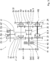
- Fig. 2 shows a first embodiment of the transmission G.
- the input clutches K1, K2 are arranged coaxially with each other.
- the second input shaft W2 is correspondingly designed as a hollow shaft, and encloses the first input shaft W1 at least in sections.
- On the first input shaft W1 three gears designed as fixed gears ZS, 46, 2R are arranged.
- On the second input shaft W2 designed as a fixed gear 35 is arranged.
- the transmission G has two countershafts VG1, VG2.
- On the first countershaft VG1 three designed as loose wheels gears Z5, Z6, Z2 are arranged.
- On the second countershaft VG2 three designed as loose wheels gears Z3, Z4, ZR are arranged.
- the transmission G comprises seven clutches, which are referred to as S5, S6, S2, S3, S4, SR, K.
- S5, S6, S2, S3, S4, SR, K By closing the clutch S5, the idler gear 5 is connected to the first countershaft VG1.
- the gear Z6 is connected to the first countershaft VG1.
- the gear Z2 is connected to the first countershaft VG1.
- the gear Z3 is connected to the second countershaft VG2.
- the gear Z4 is connected to the second countershaft VG2.
- the clutch SR the gear ZR is connected to the second countershaft VG2.
- the gear Z3 By closing the clutch K, the gear Z3 is connected to the gear Z4.
- the actuation, ie the opening and closing of the clutches S5, S6, S2, S3, S4, SR, K is carried out by an actuator AK, for example by means of shift rails.
- the gear 35 meshes with the gears Z5 and Z3.
- the gear 46 meshes with the gear Z4 and Z6.
- the gear 2R meshes with the gear Z2 and over Fig. 1 not shown intermediate wheel, which meshes with the gear ZR.
- Both countershafts VG1, VG2 are connected via spur gears Ab1, Ab2 to the output shaft GW2.
- the transmission G further has a further shaft WZ, which is arranged axially parallel to the input shafts W1, W2 and axially parallel to the countershafts VG1, VG2.
- the other shaft are assigned to three gears ZS1, ZS2, ZS3.
- the gear ZS1 is designed as a fixed wheel.
- the gears ZS2, ZS3 are designed as idler gears.
- a torque transmission between the gear ZS2 and the further shaft WZ takes place by closing a first clutch Z1.
- a torque transmission between the gear ZS3 and the further shaft WZ takes place by closing a second clutch Z2.
- the clutches Z1, Z2 are arranged coaxially with the further shaft WZ.
- the gears ZS1, ZS2, ZS3 and the clutches Z1, Z2 are part of two switchable torque transmission paths L1, L2 between the two input shafts W1, W2.
- the two torque transmission paths are formed by a first gear pair, a second gear pair and a third gear pair.
- the first gear pair results from the gears 35 and ZS1.
- the second gear pair results from the gears ZS and ZS2.
- the third gear pairing results from the gears 46 and ZS3.
- the gears 35, ZS1; ZS, ZS2; 46, ZS3 of the respective gear pairings mesh with each other.
- the first gear pair is part of both torque transmission paths L1, L2.
- the second gear pair is part of the first torque transmission path L1.
- the second gear pair is part of the second torque transmission path L2.
- the gear ZS which is part of the second gear pair and thus the first torque transmission path L1, unlike the gear 35 of the first gear pair and the gear 46 of the third gear pairing does not contribute to the gear formation, but serves exclusively to form the first torque transmission path L1.
- the gear ZS is preferably integrally connected to the gear 46, and is disposed axially between the gears 35 and 46.
- Fig. 3 shows a second embodiment of the transmission G, which substantially the in Fig. 2 corresponds to the first embodiment shown.
- the gear G now has an additional gear ZSX, which is designed as a fixed gear of the first input shaft W1.
- the additional gear ZSX meshes with the gear ZS3 instead of the gear 46, is thus part of the second torque transmission path L2 and is not involved in the formation of a gear.
- the additional gear ZSX is arranged axially between the gear ZS and the gear 46.
- the actuator AK is in Fig. 3 for the sake of clarity not shown.
- Fig. 4 shows a switching table, which is applicable to both embodiments of the transmission G.
- gears 1 to 7, R1, R2 are listed in the order of their gear row.
- the clutches S5, S6, S2, S3, S4, SR, K and the input clutches K1, K2 are listed. Circles denote the closed state of the clutches S5, S6, S2, S3, S4, SR, K and the input clutches K1, K2 in gears 1 to 7, R1, R2. From the circuit diagram it is clear that the two clutches Z1, Z2, and thus the two torque transmission paths L1, L2 do not contribute to the gear formation of the gear G.
- the increments between adjacent in the corridor series of the gear G are preferably not identical.
- the increment between gear 1 and gear 2 is greater than the increment between gear 5 and gear 6.
- Such a degressive gear is advantageous for use in the motor vehicle powertrain.
- the transmission ratio iZ1, iZ2 at least one, preferably both of the torque transmission paths L1, L2 is exemplarily greater than the largest increment between adjacent gears in the same direction of rotation direction. Gears of the same direction of rotation designate gears in which drive shaft GW1 and output shaft GW2 have the same direction of rotation.
- the frictionally engaged clutch Z2 can be actuated so that a torque MZ2 is transmitted via the torque transmission path L2. Due to the gear ratio iZ2 of the torque transmission path L2, the torque MZ2 counteracts the drag torque on the input clutch K1, so that the torque load on the still closed clutch S2 is reduced. Now, the clutch S2 can be opened with little effort by the actuator AK. With sufficiently accurate control and sufficiently large gear ratio iZ2, the clutch S2 can even be made completely load-free by operating the frictionally engaged clutch Z2.
- the first or the second frictional clutch Z1, Z2 is actuated. Due to the different transmission ratios iZ1, iZ2 of the torque transmission paths L1, L2, the load of the clutch to be opened can be correspondingly reduced. Similarly, one of the torque transmitting paths L1, L2 can be used to reduce the load on a clutch to be closed.
- Fig. 5 shows a drive train for a motor vehicle.
- an internal combustion engine VKM is connected to the transmission G via an intermediate torsional vibration damper TS.
- the transmission G is the output side, a differential gear AG downstream, via which a drive power to drive wheels DW a drive axle of the motor vehicle is distributed.
- the gear G and the torsional vibration damper TS are arranged in a common housing of the transmission G, in which then the differential gear AG can be integrated.
- the internal combustion engine VKM, the torsional vibration damper TS, the gear G and the differential gear AG are aligned transversely to a direction of travel of the motor vehicle.
- the transmission G comprises a control unit ECU, which is set up at least for controlling the actuators AK and for controlling the frictionally engaged clutches Z1, Z2.
- On the control unit ECU may be stored a map which is used to control the frictional clutches Z1, Z2 used.
Abstract
Description
- Die Erfindung betrifft ein Getriebe für ein Kraftfahrzeug, beispielsweise ein Doppelkupplungsgetriebe, sowie ein Verfahren zum Betrieb eines solchen Getriebes. Die Erfindung betrifft ferner einen Kraftfahrzeug-Antriebsstrang mit einem solchen Getriebe, sowie eine Steuereinheit zur Steuerung des vorgenannten Verfahrens.
- Die Patentanmeldung
DE 102 25 331 A1 beschreibt ein Lastschaltgetriebe mit einer Zentralsynchronisierung. Das Lastschaltgetriebe weist zwei Eingangswellen, eine Vorgelegewelle und eine Nebenwelle auf. Zur zentralen Synchronisierung der als unsynchronisiert ausgeführten Schaltelemente sind zwei Synchronelemente vorgesehen, welche auf der Nebenwelle angeordnet ist. Die zwei Synchronelemente sind zur Herstellung einer Drehmomentübertragung zwischen den Eingangswellen vorgesehen. Die Drehmomentübertragung zwischen der Nebenwelle und den Eingangswellen erfolgt über Zahnradpaarungen, welche an der Gangbildung des Lastschaltgetriebes beteiligte Zahnräder nutzen. Durch Ansteuerung der Synchronelemente kann eine Synchronisierung der Schaltelemente sowohl bei einem Hochschaltvorgang als auch bei einem Rückschaltvorgang durchgeführt werden. - Die Patentanmeldung
AT 511 631 A1 - Die im vorgenannten Stand der Technik beschriebenen Zentralsynchronisierungen dienen ausschließlich der Synchronisierung, und erhöhen im Vergleich zur herkömmlichen Sperrsynchronisierungseinrichtungen sowohl den Bauaufwand als auch den Steuerungsaufwand des Getriebes. Es ist Aufgabe der Erfindung einen zusätzlichen Nutzen derartiger Einrichtungen bereitzustellen.
- Die Aufgabe wird gelöst durch die Merkmale des Patentanspruchs 1. Die Aufgabe wird ferner gelöst durch die Merkmale des Patentanspruchs 5. Vorteilhafte Ausgestaltungen ergeben sich aus den Unteransprüchen, der Beschreibung sowie aus den Figuren.
- Es wird ein Getriebe für ein Kraftfahrzeug vorgeschlagen, welches eine Antriebswelle, eine erste und eine zweite Eingangskupplung, eine erste und einer zweite Eingangswelle, eine Mehrzahl von Schaltkupplungen sowie eine Abtriebswelle umfasst. Durch Schließen der ersten Eingangskupplung ist die Antriebswelle mit der ersten Eingangswelle verbindbar. Durch Schließen der zweiten Eingangskupplung ist die Antriebswelle mit der zweiten Eingangswelle verbindbar. Durch selektives Schließen der Schaltkupplungen und der Eingangskupplungen sind verschiedene Gänge zwischen der Antriebswelle und der Abtriebswelle darstellbar. Ferner ist zumindest ein erster schaltbarer Drehmomentübertragungspfad zwischen den beiden Eingangswellen vorgesehen. Zur Herstellung der Drehmomentübertragung umfasst der Drehmomentübertragungspfad eine reibschlüssige Kupplung. Dabei handelt es sich ausdrücklich nicht um eine der beiden Eingangskupplungen.
- Erfindungsgemäß ist ein Übersetzungsverhältnis des ersten Drehmomentübertragungspfads zwischen den Eingangswellen größer als der größte Stufensprung zwischen zwei in einer Gangreihe benachbarten Gängen gleicher Drehrichtung. Unter "Stufensprung" wird das Verhältnis zwischen den Übersetzungsverhältnissen zweier Gangstufen verstanden. Der Begriff "Gangreihe" kennzeichnet die Reihenfolge der Gänge entsprechend ihrer Übersetzungsverhältnisse. In der Gangreihe benachbarte Gänge sind beispielsweise der erste Gang und der zweite Gang; bzw. der zweite Gang und der dritte Gang, etc.
- Der Erfindung liegt die Kenntnis zu Grunde, dass die bei einem Gangwechsel oder Gangeinlegen erforderliche Kraft, um eine Schaltkupplung zu öffnen und/oder zu schließen, häufig nicht unerheblich ist. Sind die Eingangskupplungen beispielsweise als nasslaufende Lamellenkupplungen ausgebildet, so weisen diese besonders bei kaltem, zähflüssigem Öl auch im geöffneten Zustand ein hohes Schleppmoment auf.
- Ist die für einen Gangwechsel zu schließende Schaltkupplung beispielsweise als formschlüssige Kupplung ausgebildet, so muss das vorgenannte Schleppmoment zum Auflösen einer Zahn-auf-Zahn-Stellung überwunden werden. Bei einer geschlossenen Schaltkupplung führt das Schleppmoment zu einem Drehmoment zwischen den Hälften der Schaltkupplung, welche das Öffnen derselben erschweren kann. Das Schleppmoment wird durch Reibung in den Lagerstellen und an Dichtungen weiter erhöht. All dies erhöht eine zur Betätigung, also zum Öffnen oder Schlie-ßen der Schaltkupplung erforderliche Betätigungskraft. Auch die zur Verzögerung oder Beschleunigung der beim Schaltvorgang beteiligten Massenträgheiten kann die erforderliche Betätigungskraft der jeweiligen Schaltkupplung erhöhen.
- Für einen erfolgreichen Synchronisiervorgang bei einem Gangwechsel zwischen in der Gangreihe benachbarten Gängen muss das Übersetzungsverhältnis des Drehmomentübertragungspfades nur gleich groß oder geringfügig kleiner sein als der Stufensprung zwischen diesen beiden Gängen. Durch die erfindungsgemäße Auslegung des Übersetzungsverhältnisses des Drehmomentübertragungspfads kann die zur Betätigung der jeweiligen Schaltkupplung erforderliche Kraft deutlich reduziert werden, da über den Drehmomentübertragungspfad ein von einer Eingangswelle zur anderen Eingangswelle vergrößertes Drehmoment übertragen werden kann. Dieses vergrößerte Drehmoment ermöglicht eine vollständige oder teilweise Kompensation des Schleppmoments, welches auf die zu öffnende oder zu schließende Schaltkupplung wirkt. Dadurch kann eine maximale Betätigungskraft einer Aktuatorik zum Betätigen der Schaltkupplung reduziert werden, sodass dieser kleiner und leichter ausgestaltet werden kann. Ein solcher Vorgang ist unabhängig von einer Synchronisierung der Drehzahlen zwischen den Eingangswellen, und geht somit über die im Stand der Technik bekannte Verwendung einer solchen Zentralsynchronisierung hinaus.
- Vorzugsweise weist das Getriebe einen zweiten schaltbaren Drehmomentübertragungspfad zwischen den beiden Eingangswellen auf. Zur Herstellung der Drehmomentübertragung umfasst der zweite Drehmomentübertragungspfad eine weitere reibschlüssige Kupplung. Dabei handelt es sich ausdrücklich nicht um eine der beiden Eingangskupplungen. Das Übersetzungsverhältnis des zweiten Drehmomentübertragungspfads ist ebenso größer als der größte Stufensprung zwischen zwei in der Gangreihe benachbarten Gängen gleicher Drehrichtung. Gänge gleicher Drehrichtung bezeichnen Gänge, bei denen Antriebswelle und Abtriebswelle die gleiche Drehrichtung aufweisen.
- Der zweite Drehmomentübertragungspfad ermöglicht das Aufbringen eines Drehmoments auf die zu betätigende Schaltkupplung mit einem gegenüber dem ersten Drehmomentübertragungspfad unterschiedlichen Vorzeichen. In anderen Worten kann beispielsweise das auf die Schaltkupplung wirkende Drehmoment mittels des ersten Drehmomentübertragungspfads verringert, und mittels des zweiten Drehmomentübertragungspfads erhöht werden. Dadurch kann die maximale Betätigungskraft der Aktuatorik zum Betätigen der jeweiligen Schaltkupplung auch dann reduziert werden, wenn die auf diese Schaltkupplung wirkenden Lastrichtungen unterschiedlich sind.
- Bei Vergleich der Übersetzungsverhältnisse der beiden Drehmomentübertragungspfade ist die jeweilige Lastrichtung zu beachten. In anderen Worten ist das Übersetzungsverhältnis des ersten Drehmomentübertragungspfads beispielsweise durch das Übersetzungsverhältnis zwischen erster und zweiter Eingangswelle zu bestimmen, und das Übersetzungsverhältnis des zweiten Drehmomentübertragungspfads durch das Übersetzungsverhältnis zwischen zweiter und erster Eingangswelle.
- Vorzugsweise sind zumindest ein Teil der Schaltkupplungen des Getriebes als unsynchronisierte, formschlüssige Schaltelemente ausgebildet. Bei derartigen Schaltkupplungen ist eine weitgehende Reduktion des übertragenen Drehmoments Bedingung für ein Öffnen, bzw. Schließen derselben. Eine Reduktion des übertragenen Drehmoments mittels der ersten oder des zweiten Drehmomentübertragungspfads ist für derartige Schaltelemente daher besonders hilfreich.
- Das Getriebe kann Bestandteil eines Antriebsstrangs für ein Kraftfahrzeug sein. Der Antriebsstrang weist neben dem Getriebe auch einen Verbrennungsmotor auf, welcher mit der Antriebswelle verbunden, oder über eine Trennkupplung verbindbar sein kann. Zwischen Verbrennungsmotor und Antriebswelle können Vorrichtungen zur Reduzierung von Drehschwingungen vorgesehen sein, beispielsweise ein Drehschwingungsdämpfer und/oder ein Drehschwingungstilger. Die Abtriebswelle des Getriebes kann mit einem getriebe-internen oder getriebe-externen Differentialgetriebe wirkverbunden sein, welches mit Rädern des Kraftfahrzeugs wirkverbunden ist. Das Getriebe kann eine elektrische Maschine aufweisen, welche zum Antrieb des Kraftfahrzeugs mit der Antriebswelle, einer der Eingangswellen oder der Abtriebswelle verbunden ist.
- Das gegenständliche Getriebe ist für einen Antriebsstrang mit zumindest einer elektrischen Maschine besonders geeignet, und zwar unabhängig davon ob die elektrische Maschine Bestandteil des Getriebes ist oder nicht. Denn soll mittels der elektrischen Maschine im Schubbetrieb rekuperiert werden, so sollen auch Schubrückschaltungen ohne wesentliche Unterbrechung des Leistungsflusses zwischen Abtriebswelle und elektrischer Maschine erfolgen. Soll die Schubrückschaltung durch überschneidendes Öffnen und Schließen der Eingangskupplungen erfolgen, so ist für das vorhergehende Einlegen der Schaltkupplungen eine besonders leistungsfähige Synchronisierung von Vorteil, insbesondere wenn die elektrische Maschine mit der Antriebswelle verbunden ist.
- Ferner wird ein Verfahren zur Steuerung eines Getriebes angegeben, dessen Aufbau dem zuvor beschriebenen Getriebe im Wesentlichen entspricht. Dabei wird gleichzeitig zu einer Ansteuerung der Aktuatorik zum Öffnen zumindest einer der Schaltkupplungen die reibschlüssige Kupplung des ersten Drehmomentübertragungspfads betätigt, um die Schaltkupplung zumindest teilweise zu entlasten. Umfasst das Getriebe gegebenenfalls auch den zweiten Drehmomentübertragungspfad, so kann - abhängig von der erforderlichen Lastrichtung zur Entlastung der Schaltkupplung - die reibschlüssige Kupplung des zweiten Drehmomentübertragungspfads gleichzeitig zur Ansteuerung der Aktuatorik zum Öffnen dieser Schaltkupplung betätigt werden, um die Schaltkupplung zumindest teilweise zu entlasten.
- Unter "gleichzeitig" ist eine zeitliche Überschneidung der aktiven Drehmomentübertragung des ersten, bzw. zweiten Drehmomentübertragungspfads und der Aktuatorik-Ansteuerung zum Öffnen der Schaltkupplung zu verstehen. Diese beiden Tätigkeiten müssen daher nicht gleichzeitig beginnen oder gleichzeitig enden, sondern lediglich zumindest zeitweise gleichzeitig ablaufen. Dadurch kann der Öffnungsvorgang der Schaltkupplung entsprechend unterstützt werden.
- Vorzugsweise wird die reibschlüssige Kupplung des ersten oder zweiten Drehmomentübertragungspfads derart betätigt, dass die zu öffnende Schaltkupplung lastfrei wird. Dadurch kann der Kraftbedarf der Aktuatorik zum Öffnen der Schaltkupplung auf ein Minimum reduziert werden.
- Gemäß einer bevorzugten Ausgestaltung wird die reibschlüssige Kupplung des ersten oder zweiten Drehmomentübertragungspfads nicht nur gleichzeitig zum Öffnen, sondern auch gleichzeitig zum Schließen zumindest einer der Schaltkupplungen betätigt. Denn auch für den Schließvorgang ist eine Reduktion des auf die Schaltkupplung wirkendenden Drehmoments von Vorteil.
- Vorzugsweise wird das Drehmoment, welches von der reibschlüssigen Kupplung des ersten oder zweiten Drehmomentübertragungspfades zur zumindest teilweisen Entlastung der Schaltkupplung übertragen wird, aus einem Kennfeld bestimmt. Dazu kann beispielweise eine Steuereinheit vorgesehen sein, auf der das Kennfeld gespeichert ist. Vorzugsweise definiert das Kennfeld für jede Betätigungsanforderung aller oder ausgewählter Schaltkupplungen einen bestimmten Drehmomentbetrag und gegebenenfalls eine Vorgabe, mittels welcher der reibschlüssigen Kupplungen dieser Drehmomentbetrag umzusetzen ist. Eine entsprechende Aktuatorik steht mit der Elektronikeinheit in Kommunikationsverbindung und betätigt die erste, bzw. die zweite reibschlüssige Kupplung in entsprechender Weise.
- Das Kennfeld kann experimentell ermittelt werden, beispielsweise an einem Prüfstand. Zusätzlich oder alternativ dazu kann das Kennfeld anhand eines Prüflaufs nach Fertigung des Getriebes erstellt, bzw. adaptiert werden. Dadurch können während der Fertigung des Getriebes unvermeidliche Streuungen berücksichtigt werden. Im Kennfeld können verschiedene Parameter berücksichtigt werden, welche einen Einfluss auf die Entlastung der Schaltkupplungen haben, darunter beispielsweise eine Drehzahl, eine Öltemperatur und das Vorhandensein einer Ölzufuhr zur Kühlung einer der Eingangskupplungen.
- Vorzugsweise wird das Kennfeld während des Betriebs des Getriebes adaptiert. Unter einer "Adaption" wird hierbei das Berücksichtigen veränderlicher Parameter in der Ansteuerung der ersten und/oder zweiten reibschlüssigen Kupplung verstanden. Beispielsweise kann nach einem Öffnungsvorgang einer Schaltkupplung, welcher durch Ansteuerung einer der Drehmomentübertragungspfade unterstützt wurde, die Drehmomentübertragung dieses Drehmomentübertragungspfads aufrechterhalten werden. Dies führt zu einer messbaren Drehzahlveränderung einer der Eingangswellen, welche von einer Massenträgheit dieser Eingangswelle und der entsprechend gekoppelten Elemente abhängig ist. Ist diese Massenträgheit bekannt, so kann die gemessene Drehzahlveränderung mit einer erwarteten Drehzahlveränderung verglichen werden, und ein entsprechender Korrekturfaktor zur Veränderung der bisher im Kennfeld hinterlegten Werte gebildet werden.
- Besonders bevorzugt erfolgt die Adaption des Kennfelds außerhalb von Schaltvorgängen des Getriebes. Beispielsweise kann eine der reibschlüssigen Kupplungen derart angesteuert werden, dass sich - ohne Vorliegen einer Schaltanforderung - bei einer der Schaltkupplungen eine Differenzdrehzahl von Null ergibt. Ergänzend oder alternativ dazu kann eine der reibschlüssigen Kupplungen derart angesteuert werden, dass sich - ohne Vorliegen einer Schaltanforderung -eine konstante Drehzahl einer der Eingangswellen ergibt. Die zur Erreichung eines oder beider dieser Zustände erforderliche Ansteuerung der reibschlüssigen Kupplung wird gegebenenfalls um dynamische Effekte wie Anteil der Massenträgheit und vorliegender Abtriebswellen-Beschleunigung bereinigt. Daraus kann ein Korrekturfaktor zur Veränderung der bisher im Kennfeld vorhandenen Werte ermittelt werden.
- Gemäß einer bevorzugten Ausgestaltung des Verfahrens wird bei einer Betätigung zumindest einer der Schaltkupplungen eine Relativbewegung in einer Betätigungsrichtung zwischen Hälften dieser Schaltkupplung überwacht, beispielsweise mittels eines Lagesensors oder einer veränderten Zustandsgröße der entsprechenden Aktuatorik. Ein Betrag des über den ersten oder zweiten Drehmomentübertragungspfad übertragenen Drehmoments wird vorzugsweise erhöht, und zwar vorzugsweise rampenartig, wenn die Relativbewegung nicht innerhalb einer vorgegebenen Zeitspanne beginnt, oder wenn diese innerhalb der vorgegebenen Zeitspanne eine definierte Wegstrecke weder erreicht noch überschreitet. Der Betrag vor dieser Erhöhung kann Null sein, bzw. das Minimum eines von der jeweiligen reibschlüssigen Kupplung übertragbaren Drehmoments, sodass die Unterstützung zum Öffnen oder Schließen der Schaltkupplung mittels des zumindest einen Drehmomentübertragungspfades erst dann erfolgt, falls der Betätigungsvorgang ohne diese Unterstützung nicht durchgeführt werden konnte. Alternativ dazu kann der Betrag vor dieser Erhöhung größer Null sein, bzw. größer als das minimal übertragbare Drehmoment der reibschlüssigen Kupplung.
- Für das zuvor beschriebene Verfahren und dessen bevorzugten Ausführungen müssen die Übersetzungsverhältnisse des ersten und gegebenenfalls des zweiten Drehmomentübertragungspfades nicht zwingend größer sein als der größte Stufensprung zwischen zwei in einer Gangreihe benachbarten Gänge gleicher Drehrichtung. Sind diese Übersetzungsverhältnisse jedoch derart ausgeführt, so kann die Wirkung der Schaltkupplungsentlastung verbessert werden. Denn die Vergrößerung der Übersetzungsverhältnisse des ersten und gegebenenfalls des zweiten Drehmomentübertragungspfades verlängert sozusagen den Hebel, welcher zur Entlastung der zu betätigenden Schaltkupplung zur Verfügung steht.
- Es kann eine Steuereinheit vorgesehen sein, welche zur Steuerung des zuvor beschriebenen Verfahrens und dessen bevorzugten Ausführungen eingerichtet ist. Insbesondere kann es sich dabei um eine elektronische Steuereinheit handeln, welche vorzugsweise mit einer hydraulischen Steuereinheit in Kommunikationsverbindung steht.
- Ausführungsbeispiele der Erfindung sind nachfolgend anhand der beigefügten Figuren detailliert beschrieben. Es zeigen:
-
Fig. 1 eine abstrakte Darstellung eines Getriebes; -
Fig. 2 ein Getriebe gemäß einem ersten Ausführungsbeispiel; -
Fig. 3 ein Getriebe gemäß einem zweiten und dritten Ausführungsbeispiel; -
Fig. 4 ein Schaltschema für die Getriebe gemäß den beiden Ausführungsbeispielen; und -
Fig. 5 einen Antriebsstrang für ein Kraftfahrzeug. -
Fig. 1 zeigt eine abstrakte Darstellung eines Getriebes G. Das Getriebe G weist eine Antriebswelle GW1, ein erstes und zweites Teilgetriebe TG1, TG2, unsynchronisierte formschlüssige Schaltkupplungen S1a, S2a, S3a, S4a, S5a und eine Abtriebswelle GW2 auf. Dem ersten Teilgetriebe TG1 ist eine erste Eingangswelle W1 zugeordnet, welche durch Schließen einer ersten Eingangskupplung K1 mit der Antriebswelle GW1 verbindbar ist. Dem zweiten Teilgetriebe TG2 ist eine zweite Eingangswelle W2 zugeordnet, welche durch Schließen einer zweiten Eingangskupplung K2 mit der Antriebswelle GW1 verbindbar ist. Beide Teilgetriebe TG1, TG2 sind ausgangsseitig mit der Abtriebswelle GW2 verbunden. - Dem ersten Teilgetriebe TG1 sind Übersetzungsstufen i1, i2 zugeordnet. Dem zweiten Teilgetriebe TG2 sind Übersetzungsstufen i3, i4 zugeordnet. Die Übersetzungsstufen i1, i2, i3, i4 sind beispielsweise als Stirnradstufen ausgebildet, und weisen voneinander unterschiedliche Übersetzungsverhältnisse auf. Durch selektives Schließen der Schaltkupplungen S1a, S2a, S3a, S4a, S5a und der Eingangskupplungen K1, K2 werden verschiedene Gänge zwischen der Antriebswelle GW1 und der Abtriebswelle GW2 dargestellt. Die Schaltkupplung S5a verbindet die beiden Teilgetriebe TG1, TG2, sodass ein Leistungsfluss von Antriebswelle GW1 zu Abtriebswelle GW2 über Übersetzungsstufen i2, i3 beider Teilgetriebe TG1, TG2 verläuft. Ein derartiger gebildeter Gang wird auch als Windungsgang bezeichnet.
- Das Getriebe G weist ferner einen ersten und einen zweiten schaltbaren Drehmomentübertragungspfad L1, L2 zwischen den Eingangswellen W1, W2 auf. Der erste Drehmomentübertragungspfad L1 umfasst eine erste Kupplung Z1 und ein erstes Übersetzungsverhältnis iZ1. Der zweite Drehmomentübertragungspfad L2 umfasst eine zweite Kupplung Z2 und ein zweites Übersetzungsverhältnis iZ2. Die erste Kupplung Z1 und die zweite Kupplung Z2 sind jeweils als reibschlüssige Kupplungen ausgebildet.
- Die beiden Drehmomentübertragungspfade L1, L2 dienen zur Synchronisierung der Schaltkupplungen S1a, S2a, S3a, S4a, S5a. Ist beispielsweise die erste Eingangskupplung K1 und die Schaltkupplung S1a geschlossen sowie die zweite Eingangskupplung K2 geöffnet, so kann durch geeignete Ansteuerung der ersten Kupplung Z1 oder der zweiten Kupplung Z2 ein Drehmoment MZ1, MZ2 von der ersten Eingangswelle W1 auf die zweite Eingangswelle W2 übertragen werden, um die zweite Eingangswelle W2 je nach Bedarf auf eine Zieldrehzahl zu beschleunigen oder abzubremsen, um bei geöffneter Eingangskupplung K2 beispielsweise die Schaltkupplung S3a schließen zu können. Die beiden Übersetzungsverhältnisse iZ1, iZ2 sind dabei voneinander unterschiedlich. Beispielhaft dient der erste Drehmomentübertragungspfad L1 zum Beschleunigen der zweiten Eingangswelle W2 im Verhältnis zu einer Drehzahl der ersten Eingangswelle W1, und der zweite Drehmomentübertragungspfad L2 zum Verzögern der zweiten Eingangswelle W2 im Verhältnis zur Drehzahl der ersten Eingangswelle W1. Hat die zweite Eingangswelle W2 ihre Zieldrehzahl erreicht, so kann die Schaltkupplung S3a geschlossen werden. Ein Gangwechsel kann nun durch gleichzeitiges Öffnen der ersten Eingangskupplung K1 und Schlie-ßen der zweiten Eingangskupplung K2 erfolgen, ohne die Zugkraft zwischen Antriebswelle GW1 und Abtriebswelle GW2 zu unterbrechen. Die in
Fig. 1 angegebenen Pfeilrichtungen der Drehmomente MZ1, MZ2 dienen lediglich zur Illustration, und sind nicht einschränkend. - In gleicher Weise dienen die beiden Drehmomentübertragungspfade L1, L2 zum Beschleunigen oder Abbremsen der ersten Eingangswelle W1 auf eine Zieldrehzahl. Der erste Drehmomentübertragungspfad L1 dient nun zum Verzögern der ersten Eingangswelle W1 im Verhältnis zur Drehzahl der zweiten Eingangswelle W2, und der zweite Drehmomentübertragungspfad L2 dient nun zum Beschleunigen der ersten Eingangswelle W1 im Verhältnis zur Drehzahl der zweiten Eingangswelle W2. Derart können die jeweils zu schließenden Schaltkupplungen S1a, S2a, S3a, S4a, S5a sowohl bei einem Hochschaltvorgang als auch bei einem Rückschaltvorgang synchronisiert werden. Die beiden Drehmomentübertragungspfade L1, L2 dienen hier beispielhaft nicht zur Gangbildung. Bei entsprechender Auslegung der Kupplungen Z1, Z2 kann zumindest einer der Drehmomentübertragungspfade L1, L2 jedoch auch zur Gangbildung verwendet werden.
- Einer der beiden Drehmomentübertragungspfade L1, L2 kann gegebenenfalls entfallen. Beispielsweise können einige der Schaltkupplungen S1a, S2a, S3a, S4a, S5a mit einer herkömmlichen Sperrsynchronisierung versehen sein, sodass die Synchronisation bei bestimmten Gangschaltungen auch ohne Nutzung der Drehmomentübertragungspfade L1, L2 erfolgen kann. Alternativ dazu könnte eine elektrische Maschine an einer der Eingangswellen W1, W2 angebunden sein, welche zur Synchronisation eingesetzt werden kann.
-
Fig. 2 zeigt ein erstes Ausführungsbeispiel des Getriebes G. Die Eingangskupplungen K1, K2 sind koaxial zueinander angeordnet. Die zweite Eingangswelle W2 ist entsprechend als Hohlwelle ausgebildet, und umschließt die erste Eingangswelle W1 zumindest abschnittsweise. Auf der ersten Eingangswelle W1 sind drei als Festräder ausgeführte Zahnräder ZS, 46, 2R angeordnet. Auf der zweiten Eingangswelle W2 ist ein als Festrad ausgeführtes Zahnrad 35 angeordnet. Das Getriebe G weist zwei Vorgelegewellen VG1, VG2 auf. Auf der ersten Vorgelegewelle VG1 sind drei als Losräder ausgeführte Zahnräder Z5, Z6, Z2 angeordnet. Auf der zweiten Vorgelegewelle VG2 sind drei als Losräder ausgeführte Zahnräder Z3, Z4, ZR angeordnet. Das Getriebe G gemäß dem ersten Ausführungsbeispiel umfasst sieben Schaltkupplungen, welche als S5, S6, S2, S3, S4, SR, K bezeichnet sind. Durch Schließen der Schaltkupplung S5 wird das Losrad 5 mit der ersten Vorgelegewelle VG1 verbunden. Durch Schließen der Schaltkupplung S6 wird das Zahnrad Z6 mit der ersten Vorgelegewelle VG1 verbunden. Durch Schließen der Schaltkupplung S2 wird das Zahnrad Z2 mit der ersten Vorgelegewelle VG1 verbunden. Durch Schließen der Schaltkupplung S3 wird das Zahnrad Z3 mit der zweiten Vorgelegewelle VG2 verbunden. Durch Schließen der Schaltkupplung S4 wird das Zahnrad Z4 mit der zweiten Vorgelegewelle VG2 verbunden. Durch Schließen der Schaltkupplung SR wird das Zahnrad ZR mit der zweiten Vorgelegewelle VG2 verbunden. Durch Schließen der Schaltkupplung K wird das Zahnrad Z3 mit dem Zahnrad Z4 verbunden. Das Betätigen, also das Öffnen und Schließen der Schaltkupplungen S5, S6, S2, S3, S4, SR, K erfolgt durch eine Aktuatorik AK, beispielsweise mittels Schaltstangen. Das Zahnrad 35 kämmt mit den Zahnrädern Z5 und Z3. Das Zahnrad 46 kämmt mit den Zahnrad Z4 und Z6. Das Zahnrad 2R kämmt mit dem Zahnrad Z2 und über einFig. 1 nicht dargestelltes Zwischenrad, welches mit dem Zahnrad ZR kämmt. Beide Vorgelegewellen VG1, VG2 sind über Stirnradstufen Ab1, Ab2 mit der Abtriebswelle GW2 verbunden. - Das Getriebe G weist ferner eine weitere Welle WZ auf, welche achsparallel zu den Eingangswellen W1, W2 und achsparallel zu den Vorgelegewellen VG1, VG2 angeordnet ist. Der weiteren Welle sind drei Zahnräder ZS1, ZS2, ZS3 zugeordnet. Das Zahnrad ZS1 ist als Festrad ausgebildet. Die Zahnräder ZS2, ZS3 sind als Losräder ausgebildet. Eine Drehmomentübertragung zwischen Zahnrad ZS2 und der weiteren Welle WZ erfolgt durch Schließen einer ersten Kupplung Z1. Eine Drehmomentübertragung zwischen Zahnrad ZS3 und der weiteren Welle WZ erfolgt durch Schließen einer zweiten Kupplung Z2. Die Kupplungen Z1, Z2 sind koaxial zur weiteren Welle WZ angeordnet.
- Die Zahnräder ZS1, ZS2, ZS3 und die Kupplungen Z1, Z2 sind Bestandteil von zwei schaltbaren Drehmomentübertragungspfaden L1, L2 zwischen den beiden Eingangswellen W1, W2. Die beiden Drehmomentübertragungspfade sind durch eine erste Zahnradpaarung, eine zweite Zahnradpaarung und eine dritte Zahnradpaarung gebildet. Die erste Zahnradpaarung ergibt sich durch die Zahnräder 35 und ZS1. Die zweite Zahnradpaarung ergibt sich durch die Zahnräder ZS und ZS2. Die dritte Zahnradpaarung ergibt sich durch die Zahnräder 46 und ZS3. Die Zahnräder 35, ZS1; ZS, ZS2; 46, ZS3 der jeweiligen Zahnradpaarungen kämmen miteinander. Die erste Zahnradpaarung ist Bestandteil beider Drehmomentübertragungspfade L1, L2. Die zweite Zahnradpaarung ist Bestandteil des ersten Drehmomentübertragungspfads L1. Die zweite Zahnradpaarung ist Bestandteil des zweiten Drehmomentübertragungspfads L2.
- Das Zahnrad ZS, welches Bestandteil der zweiten Zahnradpaarung und somit des ersten Drehmomentübertragungspfads L1 ist, trägt im Gegensatz zum Zahnrad 35 der ersten Zahnradpaarung und zum Zahnrad 46 der dritten Zahnradpaarung nicht zur Gangbildung bei, sondern dient ausschließlich zur Ausbildung des ersten Drehmomentübertragungspfads L1. Das Zahnrad ZS ist vorzugsweise einteilig mit dem Zahnrad 46 verbunden, und ist axial zwischen den Zahnrädern 35 und 46 angeordnet.
-
Fig. 3 zeigt ein zweites Ausführungsbeispiel des Getriebes G, welches im Wesentlichen dem inFig. 2 dargestellten ersten Ausführungsbeispiel entspricht. Das Getriebe G weist nun ein zusätzliches Zahnrad ZSX auf, welches als Festrad der ersten Eingangswelle W1 ausgebildet ist. Das zusätzliche Zahnrad ZSX kämmt anstelle des Zahnrads 46 mit dem Zahnrad ZS3, ist somit Bestandteil des zweiten Drehmomentübertragungspfads L2 und ist an der Gangbildung nicht beteiligt. Das zusätzliche Zahnrad ZSX ist axial zwischen dem Zahnrad ZS und dem Zahnrad 46 angeordnet. Die Aktuatorik AK ist inFig. 3 der Übersichtlichkeit halber nicht dargestellt. -
Fig. 4 zeigt eine Schalttabelle, welche für beide Ausführungsbeispiele des Getriebes G anwendbar ist. In den Zeilen des Schaltschemas sind Gänge 1 bis 7, R1, R2 in der Reihenfolge ihrer Gangreihe angeführt. In den Spalten sind die Schaltkupplungen S5, S6, S2, S3, S4, SR, K sowie die Eingangskupplungen K1, K2 angeführt. Kreise bezeichnen den geschlossenen Zustand der Schaltkupplungen S5, S6, S2, S3, S4, SR, K sowie der Eingangskupplungen K1, K2 in Gängen 1 bis 7, R1, R2. Aus dem Schaltschema geht deutlich hervor, dass die beiden Kupplungen Z1, Z2, und somit die beiden Drehmomentübertragungspfade L1, L2 nicht zur Gangbildung des Getriebes G beitragen. - Die Stufensprünge zwischen in der Gangreihe benachbarten Gängen des Getriebes G, also beispielsweise zwischen Gang 1 und Gang 2 oder zwischen Gang 4 und Gang 5 sind vorzugsweise nicht identisch. Beispielsweise ist der Stufensprung zwischen Gang 1 und Gang 2 größer als der Stufensprung zwischen Gang 5 und Gang 6. Eine solche degressive Gangabstufung ist für einen Einsatz im Kraftfahrzeug-Antriebsstrang von Vorteil. Das Übersetzungsverhältnis iZ1, iZ2 zumindest eines, vorzugsweise beider der Drehmomentübertragungspfade L1, L2 ist beispielhaft größer als der größte Stufensprung zwischen in der Gangreihe benachbarten Gängen gleicher Drehrichtung. Gänge gleicher Drehrichtung bezeichnen Gänge, bei denen Antriebswelle GW1 und Abtriebswelle GW2 die gleiche Drehrichtung aufweisen.
- Im Folgenden wird das erfindungsgemäße Verfahren anhand einem Beispiel näher beschrieben: in einem Ausgangszustand ist im Getriebe G der Gang 3 eingelegt, wonach die Eingangskupplung K2 sowie die Schaltkupplung S3 geschlossen sind. Zeitgleich ist die Schaltkupplung S2 geschlossen und die Eingangskupplung K1 geöffnet. Nun soll die Schaltkupplung S2 geöffnet und die Schaltkupplung S4 geschlossen werden, um für eine nachfolgende Hochschaltung von Gang 3 in Gang 4 lediglich die Eingangskupplung K2 zu öffnen und die Eingangskupplung K1 schließen zu müssen. Die Schaltkupplung S2 ist jedoch nicht lastfrei, da das Schleppmoment der geöffneten Eingangskupplung K1 über den Lastpfad des Gangs 2 auf die Abtriebswelle GW2 wirkt. Das auf die Schaltkupplung S2 wirkende Schleppmoment wird durch das Übersetzungsverhältnis zwischen dem Zahnrad 2R und dem Zahnrad Z2 zusätzlich vergrößert.
- Nun kann beispielsweise die reibschlüssige Kupplung Z2 betätigt werden, sodass über den Drehmomentübertragungspfad L2 ein Drehmoment MZ2 übertragen wird. Durch das Übersetzungsverhältnis iZ2 des Drehmomentübertragungspfads L2 wirkt das Drehmoment MZ2 dem Schleppmoment an der Eingangskupplung K1 entgegen, sodass die Drehmomentbelastung an der noch geschlossenen Schaltkupplung S2 reduziert wird. Nun kann die Schaltkupplung S2 mit geringem Kraftaufwand durch die Aktuatorik AK geöffnet werden. Bei hinreichend genauer Steuerung und ausreichend großem Übersetzungsverhältnis iZ2 kann die Schaltkupplung S2 durch Betätigung der reibschlüssigen Kupplung Z2 sogar vollständig lastfrei gestellt werden.
- Abhängig von dem Vorzeichen des Drehmoments, welches an der zu öffnenden Schaltkupplung wirkt, wird die erste oder die zweite reibschlüssige Kupplung Z1, Z2 betätigt. Durch die unterschiedlichen Übersetzungsverhältnisse iZ1, iZ2 der Drehmomentübertragungspfade L1, L2 kann die Belastung der zu öffnenden Schaltkupplung entsprechend reduziert werden. In gleicher Weise kann einer der Drehmomentübertragungspfade L1, L2 dazu verwendet werden, die Belastung einer zu schließenden Schaltkupplung zu reduzieren.
-
Fig. 5 zeigt einen Antriebsstrang für ein Kraftfahrzeug. wobei eine Verbrennungskraftmaschine VKM über einen zwischenliegenden Torsionsschwingungsdämpfer TS mit dem Getriebe G verbunden ist. Dem Getriebe G ist abtriebsseitig ein Differentialgetriebe AG nachgeschaltet, über welches eine Antriebsleistung auf Antriebsräder DW einer Antriebsachse des Kraftfahrzeuges verteilt wird. Das Getriebe G und der Torsionsschwingungsdämpfer TS sind dabei in einem gemeinsamen Gehäuse des Getriebes G angeordnet, in welches dann auch das Differentialgetriebe AG integriert sein kann. Wie zudem inFig. 5 zu erkennen ist, sind die Verbrennungskraftmaschine VKM, der Torsionsschwingungsdämpfer TS, das Getriebe G und auch das Differentialgetriebe AG quer zu einer Fahrtrichtung des Kraftfahrzeuges ausgerichtet. - Das Getriebe G umfasst eine Steuereinheit ECU, welche zumindest zur Steuerung der Aktuatorik AK und zur Steuerung der reibschlüssigen Kupplungen Z1, Z2 eingerichtet ist. Auf der Steuereinheit ECU kann ein Kennfeld hinterlegt sein, welches zur Steuerung der reibschlüssigen Kupplungen Z1, Z2 zur Anwendung kommt.
-
- G
- Getriebe
- GW1
- Antriebswelle
- GW2
- Abtriebswelle
- TG1
- Erstes Teilgetriebe
- TG2
- Zweites Teilgetriebe
- K1
- Erste Eingangskupplung
- K2
- Zweite Eingangskupplung
- S1a-S5a
- Schaltkupplungen
- i1-i4
- Übersetzungsstufen
- S2-S6, SR, K
- Schaltkupplungen
- VG1, VG2
- Vorgelegewellen
- L1, L2
- Drehmomentübertragungspfade
- iZ1, iZ2
- Übersetzungsverhältnisse der Drehmomentübertragungspfade
- Z1, Z2
- Reibschlüssige Kupplungen
- MZ1, MZ2
- Drehmoment
- Z2-Z6, ZR
- Zahnräder
- 35, 46, 2R
- Zahnräder
- ZS
- Zahnrad
- ZSX
- Zusätzliches Zahnrad
- ZS1, ZS2, ZS3
- Zahnräder
- WZ
- Weitere Welle
- Ab1, Ab2
- Stirnradstufen
- 1-7, R1, R2
- Gänge
- ECU
- Steuereinheit
- AK
- Aktuatorik
- VKM
- Verbrennungskraftmaschine
- TS
- Torsionsschwingungsdämpfer
- AG
- Differentialgetriebe
- DW
- Antriebsrad
Claims (15)
- Getriebe (G) für ein Kraftfahrzeug, wobei das Getriebe (G) eine Antriebswelle (GW1), eine über eine erste Eingangskupplung (K1) mit der Antriebswelle (GW1) verbindbare erste Eingangswelle (W1), eine über eine zweite Eingangskupplung (K2) mit der Antriebswelle (GW1) verbindbare zweite Eingangswelle (W2), eine Mehrzahl von Schaltkupplungen (S1a, S2a, S3a, S4a, S5a; S2, S3, S4, S5, S6, SR, K) sowie eine Abtriebswelle (GW2) aufweist,- wobei durch selektive Betätigung der Schaltkupplungen (S5, S6, S2, S3, S4, SR, K) und der Eingangskupplungen (K1, K2) verschiedene Gänge (1 bis 7, R1, R2) zwischen der Antriebswelle(GW1) und der Abtriebswelle (GW2) darstellbar sind,- wobei zumindest ein erster, mittels einer reibschlüssigen Kupplung (Z1) schaltbarer Drehmomentübertragungspfad (L1) zwischen der ersten Eingangswelle (W1) und der zweiten Eingangswelle (W2) vorgesehen ist,dadurch gekennzeichnet, dass ein Übersetzungsverhältnis (iZ1) des ersten Drehmomentübertragungspfads (L1) zwischen den Eingangswellen (W1, W2) größer ist als der größte Stufensprung zwischen zwei in einer Gangreihe benachbarten Gänge (1 bis 7) gleicher Drehrichtung.
- Getriebe (G) nach Anspruch 1, dadurch gekennzeichnet, dass ein zweiter, mittels einer weiteren reibschlüssigen Kupplung (Z2) schaltbarer Drehmomentübertragungspfad (L2) zwischen der ersten Eingangswelle (W1) und der zweiten Eingangswelle (W2) vorgesehen ist, wobei ein Übersetzungsverhältnis (iZ2) des zweiten Drehmomentübertragungspfads (L2) zwischen den Eingangswellen (W1, W2) größer ist als der größte Stufensprung zwischen zwei in der Gangreihe benachbarten Gänge (1 bis 7) gleicher Drehrichtung.
- Getriebe (G) nach Anspruch 1 oder Anspruch 2, dadurch gekennzeichnet, dass zumindest ein Teil der Schaltkupplungen (S1a, S2a, S3a, S4a, S5a; S2, S3, S4, S5, S6, SR, K) als unsynchronisierte, formschlüssige Schaltelemente ausgebildet sind.
- Antriebsstrang für ein Kraftfahrzeug, gekennzeichnet durch ein Getriebe (G) gemäß einem der Ansprüche 1 bis 3.
- Verfahren zum Betrieb eines Getriebes (G) für ein Kraftfahrzeug, wobei das Getriebe (G) eine Antriebswelle (GW1), eine über eine erste Eingangskupplung (K1) mit der Antriebswelle (GW1) verbindbare erste Eingangswelle (W1), eine über eine zweite Eingangskupplung (K2) mit der Antriebswelle (GW1) verbindbare zweite Eingangswelle (W2), eine Mehrzahl von Schaltkupplungen (S1a, S2a, S3a, S4a, S5a; S2, S3, S4, S5, S6, SR, K) sowie eine Abtriebswelle (GW2) aufweist,- wobei durch selektive Betätigung der Schaltkupplungen (S1a, S2a, S3a, S4a, S5a; S2, S3, S4, S5, S6, SR, K) und der Eingangskupplungen (K1, K2) verschiedene Gänge (1 bis 7, R1, R2) zwischen der Antriebswelle (GW1) und der Abtriebswelle (GW2) darstellbar sind,- wobei zumindest ein erster, mittels einer reibschlüssigen Kupplung (Z1) schaltbarer Drehmomentübertragungspfad (L1) zwischen der ersten Eingangswelle (W1) und der zweiten Eingangswelle (W2) vorgesehen ist,dadurch gekennzeichnet, dass gleichzeitig zu einer Ansteuerung einer Aktuatorik (AK) zum Öffnen zumindest einer der Schaltkupplungen (S1a, S2a, S3a, S4a, S5a; S2, S3, S4, S5, S6, SR, K) die reibschlüssige Kupplung (Z1) zur Übertragung eines Drehmoments (MZ1) zwischen den Eingangswellen (W1, W2) betätigt wird, sodass ein zwischen Hälften der zu öffnenden Schaltkupplung (S1 a, S2a, S3a, S4a, S5a; S2, S3, S4, S5, S6, SR, K) wirkendes Drehmoment reduziert wird.
- Verfahren nach Anspruch 5, dadurch gekennzeichnet, dass ein zweiter, mittels einer weiteren reibschlüssigen Kupplung (Z2) schaltbarer Drehmomentübertragungspfad (L2) zwischen der ersten Eingangswelle (W1) und der zweiten Eingangswelle (W2) vorgesehen ist, wobei gleichzeitig zu einer Ansteuerung zum Öffnen der zu öffnenden Schaltkupplung (S1a, S2a, S3a, S4a, S5a; S2, S3, S4, S5, S6, SR, K) eine der beiden reibschlüssigen Kupplungen (Z1, Z2) zur Übertragung eines Drehmoments (MZ1, MZ2) zwischen den Eingangswellen (W1, W2) betätigt wird, sodass ein zwischen den Hälften der zu öffnenden Schaltkupplung (S1 a, S2a, S3a, S4a, S5a; S2, S3, S4, S5, S6, SR, K) wirkendes Drehmoment reduziert wird.
- Verfahren nach Anspruch 5 oder Anspruch 6, dadurch gekennzeichnet, dass eine der reibschlüssigen Kupplungen (Z1, Z2) derart betätigt wird, dass die zu öffnende Schaltkupplung (S1a, S2a, S3a, S4a, S5a; S2, S3, S4, S5, S6, SR, K) lastfrei wird.
- Verfahren nach einem der Ansprüche 5 bis 7, dadurch gekennzeichnet, dass eine der reibschlüssigen Kupplung (Z1, Z2) bei einer Ansteuerung zum Schließen zumindest einer der Schaltkupplungen (S1a, S2a, S3a, S4a, S5a; S2, S3, S4, S5, S6, SR, K) zur Übertragung eines Drehmoments (MZ1, MZ2) zwischen den Eingangswellen (W1, W2) betätigt wird, sodass ein zwischen Hälften der zu schließenden Schaltkupplung (S1 a, S2a, S3a, S4a, S5a; S2, S3, S4, S5, S6, SR, K) wirkendes Drehmoment reduziert wird.
- Verfahren nach einem der Ansprüche 5 bis 8, dadurch gekennzeichnet, dass das von der reibschlüssigen Kupplung (Z1, Z2) zu übertragende Drehmoment (MZ1, MZ2) aus einem Kennfeld bestimmt wird.
- Verfahren nach Anspruch 9, dadurch gekennzeichnet, dass das Kennfeld während des Betriebs des Getriebes (G) adaptiert wird.
- Verfahren nach Anspruch 10, dadurch gekennzeichnet, dass die Adaption des Kennfelds außerhalb von Schaltvorgängen des Getriebes (G) erfolgt.
- Verfahren nach einem der Ansprüche 5 bis 11, dadurch gekennzeichnet, dass bei einer Betätigung zumindest einer der Schaltkupplungen (S1 a, S2a, S3a, S4a, S5a; S2, S3, S4, S5, S6, SR, K) eine Relativbewegung in einer Betätigungsrichtung zwischen Hälften dieser Schaltkupplung (S1 a, S2a, S3a, S4a, S5a; S2, S3, S4, S5, S6, SR, K) überwacht wird, wobei ein Betrag des Drehmoments (MZ1, MZ2), welches von der jeweils betätigten reibschlüssigen Kupplung (Z1, Z2) übertragen wird, dann erhöht wird, wenn die Relativbewegung nicht innerhalb einer vorgegebenen Zeitspanne beginnt oder eine definierte Wegstrecke weder erreicht noch überschreitet.
- Verfahren nach Anspruch 12, dass die Erhöhung des Betrags des Drehmoments (MZ1, MZ2) rampenförmig erfolgt.
- Verfahren nach einem der Ansprüche 5 bis 13, dadurch gekennzeichnet dass ein Übersetzungsverhältnis (iZ1, iZ2) einer der Drehmomentübertragungspfad e(L1, L2) zwischen den Eingangswellen (W1, W2) größer ist als der größte Stufensprung zwischen zwei in einer Gangreihe benachbarten Gänge (1 bis 7) gleicher Drehrichtung.
- Steuereinheit (ECU) für ein Kraftfahrzeuggetriebe (G), dadurch gekennzeichnet, dass die Steuereinheit (ECU) zur Steuerung des Verfahrens nach einem der Ansprüche 5 bis 14 eingerichtet ist.
Priority Applications (1)
| Application Number | Priority Date | Filing Date | Title |
|---|---|---|---|
| EP17207313.2A EP3499088B1 (de) | 2017-12-14 | 2017-12-14 | Getriebe für ein kraftfahrzeug, und verfahren zum betrieb eines solchen getriebes |
Applications Claiming Priority (1)
| Application Number | Priority Date | Filing Date | Title |
|---|---|---|---|
| EP17207313.2A EP3499088B1 (de) | 2017-12-14 | 2017-12-14 | Getriebe für ein kraftfahrzeug, und verfahren zum betrieb eines solchen getriebes |
Publications (2)
| Publication Number | Publication Date |
|---|---|
| EP3499088A1 true EP3499088A1 (de) | 2019-06-19 |
| EP3499088B1 EP3499088B1 (de) | 2020-07-01 |
Family
ID=60673565
Family Applications (1)
| Application Number | Title | Priority Date | Filing Date |
|---|---|---|---|
| EP17207313.2A Active EP3499088B1 (de) | 2017-12-14 | 2017-12-14 | Getriebe für ein kraftfahrzeug, und verfahren zum betrieb eines solchen getriebes |
Country Status (1)
| Country | Link |
|---|---|
| EP (1) | EP3499088B1 (de) |
Cited By (1)
| Publication number | Priority date | Publication date | Assignee | Title |
|---|---|---|---|---|
| US10876625B2 (en) * | 2018-06-04 | 2020-12-29 | Zf Friedrichshafen Ag | Transmission control method |
Citations (6)
| Publication number | Priority date | Publication date | Assignee | Title |
|---|---|---|---|---|
| DE4436526A1 (de) * | 1994-04-16 | 1995-10-19 | Rudolf Prof Dr Franke | Verfahren zur Synchronisierung der Schaltkupplungen eines Stirnradwechselgetriebes für ein Kraftfahrzeug und Stirnradwechselgetriebe zur Durchführung des Verfahrens |
| WO2003083325A1 (de) * | 2002-03-30 | 2003-10-09 | Zf Friedrichshafen Ag | Synchronisiereinrichtung für ein doppelkupplungsgetriebe auf grundlage wenigstens eines planetenradsatzes und entsprechendes doppelkupplungsgetriebe |
| DE10225331A1 (de) | 2001-07-15 | 2003-12-24 | Richard Boisch | Lastschaltgetriebe mit Zentralsynchronisiertung |
| DE10239540A1 (de) * | 2001-07-15 | 2004-03-11 | Boisch, Richard, Prof. Dr. | Rückwärtsgang und Zentralsynchronisierung für Lastschaltgetriebe |
| EP1400731A2 (de) * | 2002-09-18 | 2004-03-24 | Volkswagen Aktiengesellschaft | Vorrichtung zur Synchronisierung eines Doppelkupplungsgetriebes |
| AT511631A1 (de) | 2011-06-30 | 2013-01-15 | Avl List Gmbh | Doppelkupplungs-getriebe mit mehreren schaltbaren gangstufen |
-
2017
- 2017-12-14 EP EP17207313.2A patent/EP3499088B1/de active Active
Patent Citations (6)
| Publication number | Priority date | Publication date | Assignee | Title |
|---|---|---|---|---|
| DE4436526A1 (de) * | 1994-04-16 | 1995-10-19 | Rudolf Prof Dr Franke | Verfahren zur Synchronisierung der Schaltkupplungen eines Stirnradwechselgetriebes für ein Kraftfahrzeug und Stirnradwechselgetriebe zur Durchführung des Verfahrens |
| DE10225331A1 (de) | 2001-07-15 | 2003-12-24 | Richard Boisch | Lastschaltgetriebe mit Zentralsynchronisiertung |
| DE10239540A1 (de) * | 2001-07-15 | 2004-03-11 | Boisch, Richard, Prof. Dr. | Rückwärtsgang und Zentralsynchronisierung für Lastschaltgetriebe |
| WO2003083325A1 (de) * | 2002-03-30 | 2003-10-09 | Zf Friedrichshafen Ag | Synchronisiereinrichtung für ein doppelkupplungsgetriebe auf grundlage wenigstens eines planetenradsatzes und entsprechendes doppelkupplungsgetriebe |
| EP1400731A2 (de) * | 2002-09-18 | 2004-03-24 | Volkswagen Aktiengesellschaft | Vorrichtung zur Synchronisierung eines Doppelkupplungsgetriebes |
| AT511631A1 (de) | 2011-06-30 | 2013-01-15 | Avl List Gmbh | Doppelkupplungs-getriebe mit mehreren schaltbaren gangstufen |
Cited By (1)
| Publication number | Priority date | Publication date | Assignee | Title |
|---|---|---|---|---|
| US10876625B2 (en) * | 2018-06-04 | 2020-12-29 | Zf Friedrichshafen Ag | Transmission control method |
Also Published As
| Publication number | Publication date |
|---|---|
| EP3499088B1 (de) | 2020-07-01 |
Similar Documents
| Publication | Publication Date | Title |
|---|---|---|
| DE102007022456B4 (de) | Steuerungsstrategie zum Verhindern von Lastwechselgeräuschen bei einem Lastschaltgetriebe | |
| EP2818748B1 (de) | Steuerverfahren für ein doppelkupplungsgetriebe | |
| EP2457760A2 (de) | Antriebsstrang und Verfahren zum Betreiben desselben | |
| DE10004530B4 (de) | Verfahren zur Steuerung eines Doppelkupplungsgetriebes | |
| DE102014016932A1 (de) | Verfahren zum Schalten eines Gruppengetriebes eines Kraftwagens | |
| EP2921746B1 (de) | Steuerverfahren für antriebsstrang und antriebsstrang | |
| EP0873902A1 (de) | Verfahren zum Schalten eines synchronisiergliederfreien Zahnräderwechselgetriebes | |
| DE102014209970B4 (de) | Getriebe für ein Kraftfahrzeug | |
| DE102006057728A1 (de) | Verfahren zur Gangschaltsteuerung eines Lastschaltautomatikgetriebes | |
| DE10349220B4 (de) | Verfahren zum Schalten eines Doppelkupplungsgetriebes eines Kraftfahrzeuges | |
| EP3303880B1 (de) | Gruppengetriebe für einen kraftwagen sowie verfahren zum schalten eines solchen gruppengetriebes | |
| DE102012212370A1 (de) | Schaltgetriebe eines Kraftfahrzeugs | |
| DE102014208557B4 (de) | Verfahren zur Steuerung und/oder Regelung der Schaltung eines Doppelkupplungsgetriebes eines Kraftfahrzeugs | |
| WO2001074619A2 (de) | Steuerung eines getriebes mit anfahrkupplung und lastschaltkupplung | |
| EP3499088B1 (de) | Getriebe für ein kraftfahrzeug, und verfahren zum betrieb eines solchen getriebes | |
| DE19952535A1 (de) | Automatisiertes Lastschaltgetriebe und Verfahren zur Steuerung eines automatisierten Lastschaltgetriebes | |
| EP1632694B1 (de) | Antriebsstrang mit Parallelschaltgetriebe | |
| AT512917B1 (de) | Verfahren zum Betreiben eines Doppelkupplungsgetriebes | |
| DE102016106206A1 (de) | Ansteuerungsverfahren für Antriebsstrang und Getriebeanordnung für Antriebsstrang | |
| WO2005008103A1 (de) | Verfahren zum schalten eines doppelkupplungsgetriebes eines kraftfahrzeuges | |
| DE102013221912A1 (de) | Getriebe-Motor-Anordnung | |
| DE102019219959B4 (de) | Verfahren zur Schaltsteuerung eines automatisierten Gruppengetriebes | |
| DE102017222765A1 (de) | Getriebe für ein Kraftfahrzeug, und Verfahren zum Betrieb eines solchen Getriebes | |
| DE102017004637B4 (de) | Ändern einer Übersetzung in einem Getriebe eines Fahrzeugs | |
| DE102010024768A1 (de) | Kraftfahrzeuggruppengetriebevorrichtung |
Legal Events
| Date | Code | Title | Description |
|---|---|---|---|
| PUAI | Public reference made under article 153(3) epc to a published international application that has entered the european phase |
Free format text: ORIGINAL CODE: 0009012 |
|
| STAA | Information on the status of an ep patent application or granted ep patent |
Free format text: STATUS: THE APPLICATION HAS BEEN PUBLISHED |
|
| AK | Designated contracting states |
Kind code of ref document: A1 Designated state(s): AL AT BE BG CH CY CZ DE DK EE ES FI FR GB GR HR HU IE IS IT LI LT LU LV MC MK MT NL NO PL PT RO RS SE SI SK SM TR |
|
| AX | Request for extension of the european patent |
Extension state: BA ME |
|
| STAA | Information on the status of an ep patent application or granted ep patent |
Free format text: STATUS: REQUEST FOR EXAMINATION WAS MADE |
|
| 17P | Request for examination filed |
Effective date: 20191206 |
|
| GRAP | Despatch of communication of intention to grant a patent |
Free format text: ORIGINAL CODE: EPIDOSNIGR1 |
|
| STAA | Information on the status of an ep patent application or granted ep patent |
Free format text: STATUS: GRANT OF PATENT IS INTENDED |
|
| INTG | Intention to grant announced |
Effective date: 20200131 |
|
| GRAS | Grant fee paid |
Free format text: ORIGINAL CODE: EPIDOSNIGR3 |
|
| GRAA | (expected) grant |
Free format text: ORIGINAL CODE: 0009210 |
|
| STAA | Information on the status of an ep patent application or granted ep patent |
Free format text: STATUS: THE PATENT HAS BEEN GRANTED |
|
| AK | Designated contracting states |
Kind code of ref document: B1 Designated state(s): AL AT BE BG CH CY CZ DE DK EE ES FI FR GB GR HR HU IE IS IT LI LT LU LV MC MK MT NL NO PL PT RO RS SE SI SK SM TR |
|
| REG | Reference to a national code |
Ref country code: AT Ref legal event code: REF Ref document number: 1286485 Country of ref document: AT Kind code of ref document: T Effective date: 20200715 Ref country code: CH Ref legal event code: EP |
|
| REG | Reference to a national code |
Ref country code: IE Ref legal event code: FG4D Free format text: LANGUAGE OF EP DOCUMENT: GERMAN |
|
| REG | Reference to a national code |
Ref country code: DE Ref legal event code: R096 Ref document number: 502017005964 Country of ref document: DE |
|
| REG | Reference to a national code |
Ref country code: LT Ref legal event code: MG4D |
|
| PG25 | Lapsed in a contracting state [announced via postgrant information from national office to epo] |
Ref country code: BG Free format text: LAPSE BECAUSE OF FAILURE TO SUBMIT A TRANSLATION OF THE DESCRIPTION OR TO PAY THE FEE WITHIN THE PRESCRIBED TIME-LIMIT Effective date: 20201001 |
|
| REG | Reference to a national code |
Ref country code: NL Ref legal event code: MP Effective date: 20200701 |
|
| PG25 | Lapsed in a contracting state [announced via postgrant information from national office to epo] |
Ref country code: LT Free format text: LAPSE BECAUSE OF FAILURE TO SUBMIT A TRANSLATION OF THE DESCRIPTION OR TO PAY THE FEE WITHIN THE PRESCRIBED TIME-LIMIT Effective date: 20200701 Ref country code: CZ Free format text: LAPSE BECAUSE OF FAILURE TO SUBMIT A TRANSLATION OF THE DESCRIPTION OR TO PAY THE FEE WITHIN THE PRESCRIBED TIME-LIMIT Effective date: 20200701 Ref country code: HR Free format text: LAPSE BECAUSE OF FAILURE TO SUBMIT A TRANSLATION OF THE DESCRIPTION OR TO PAY THE FEE WITHIN THE PRESCRIBED TIME-LIMIT Effective date: 20200701 Ref country code: PT Free format text: LAPSE BECAUSE OF FAILURE TO SUBMIT A TRANSLATION OF THE DESCRIPTION OR TO PAY THE FEE WITHIN THE PRESCRIBED TIME-LIMIT Effective date: 20201102 Ref country code: SE Free format text: LAPSE BECAUSE OF FAILURE TO SUBMIT A TRANSLATION OF THE DESCRIPTION OR TO PAY THE FEE WITHIN THE PRESCRIBED TIME-LIMIT Effective date: 20200701 Ref country code: ES Free format text: LAPSE BECAUSE OF FAILURE TO SUBMIT A TRANSLATION OF THE DESCRIPTION OR TO PAY THE FEE WITHIN THE PRESCRIBED TIME-LIMIT Effective date: 20200701 Ref country code: NO Free format text: LAPSE BECAUSE OF FAILURE TO SUBMIT A TRANSLATION OF THE DESCRIPTION OR TO PAY THE FEE WITHIN THE PRESCRIBED TIME-LIMIT Effective date: 20201001 Ref country code: GR Free format text: LAPSE BECAUSE OF FAILURE TO SUBMIT A TRANSLATION OF THE DESCRIPTION OR TO PAY THE FEE WITHIN THE PRESCRIBED TIME-LIMIT Effective date: 20201002 Ref country code: FI Free format text: LAPSE BECAUSE OF FAILURE TO SUBMIT A TRANSLATION OF THE DESCRIPTION OR TO PAY THE FEE WITHIN THE PRESCRIBED TIME-LIMIT Effective date: 20200701 |
|
| PG25 | Lapsed in a contracting state [announced via postgrant information from national office to epo] |
Ref country code: IS Free format text: LAPSE BECAUSE OF FAILURE TO SUBMIT A TRANSLATION OF THE DESCRIPTION OR TO PAY THE FEE WITHIN THE PRESCRIBED TIME-LIMIT Effective date: 20201101 Ref country code: PL Free format text: LAPSE BECAUSE OF FAILURE TO SUBMIT A TRANSLATION OF THE DESCRIPTION OR TO PAY THE FEE WITHIN THE PRESCRIBED TIME-LIMIT Effective date: 20200701 Ref country code: LV Free format text: LAPSE BECAUSE OF FAILURE TO SUBMIT A TRANSLATION OF THE DESCRIPTION OR TO PAY THE FEE WITHIN THE PRESCRIBED TIME-LIMIT Effective date: 20200701 Ref country code: RS Free format text: LAPSE BECAUSE OF FAILURE TO SUBMIT A TRANSLATION OF THE DESCRIPTION OR TO PAY THE FEE WITHIN THE PRESCRIBED TIME-LIMIT Effective date: 20200701 |
|
| PG25 | Lapsed in a contracting state [announced via postgrant information from national office to epo] |
Ref country code: NL Free format text: LAPSE BECAUSE OF FAILURE TO SUBMIT A TRANSLATION OF THE DESCRIPTION OR TO PAY THE FEE WITHIN THE PRESCRIBED TIME-LIMIT Effective date: 20200701 |
|
| REG | Reference to a national code |
Ref country code: DE Ref legal event code: R097 Ref document number: 502017005964 Country of ref document: DE |
|
| PG25 | Lapsed in a contracting state [announced via postgrant information from national office to epo] |
Ref country code: DK Free format text: LAPSE BECAUSE OF FAILURE TO SUBMIT A TRANSLATION OF THE DESCRIPTION OR TO PAY THE FEE WITHIN THE PRESCRIBED TIME-LIMIT Effective date: 20200701 Ref country code: RO Free format text: LAPSE BECAUSE OF FAILURE TO SUBMIT A TRANSLATION OF THE DESCRIPTION OR TO PAY THE FEE WITHIN THE PRESCRIBED TIME-LIMIT Effective date: 20200701 Ref country code: SM Free format text: LAPSE BECAUSE OF FAILURE TO SUBMIT A TRANSLATION OF THE DESCRIPTION OR TO PAY THE FEE WITHIN THE PRESCRIBED TIME-LIMIT Effective date: 20200701 Ref country code: EE Free format text: LAPSE BECAUSE OF FAILURE TO SUBMIT A TRANSLATION OF THE DESCRIPTION OR TO PAY THE FEE WITHIN THE PRESCRIBED TIME-LIMIT Effective date: 20200701 Ref country code: IT Free format text: LAPSE BECAUSE OF FAILURE TO SUBMIT A TRANSLATION OF THE DESCRIPTION OR TO PAY THE FEE WITHIN THE PRESCRIBED TIME-LIMIT Effective date: 20200701 |
|
| PLBE | No opposition filed within time limit |
Free format text: ORIGINAL CODE: 0009261 |
|
| STAA | Information on the status of an ep patent application or granted ep patent |
Free format text: STATUS: NO OPPOSITION FILED WITHIN TIME LIMIT |
|
| PG25 | Lapsed in a contracting state [announced via postgrant information from national office to epo] |
Ref country code: AL Free format text: LAPSE BECAUSE OF FAILURE TO SUBMIT A TRANSLATION OF THE DESCRIPTION OR TO PAY THE FEE WITHIN THE PRESCRIBED TIME-LIMIT Effective date: 20200701 |
|
| 26N | No opposition filed |
Effective date: 20210406 |
|
| PG25 | Lapsed in a contracting state [announced via postgrant information from national office to epo] |
Ref country code: SK Free format text: LAPSE BECAUSE OF FAILURE TO SUBMIT A TRANSLATION OF THE DESCRIPTION OR TO PAY THE FEE WITHIN THE PRESCRIBED TIME-LIMIT Effective date: 20200701 |
|
| REG | Reference to a national code |
Ref country code: CH Ref legal event code: PL |
|
| PG25 | Lapsed in a contracting state [announced via postgrant information from national office to epo] |
Ref country code: MC Free format text: LAPSE BECAUSE OF FAILURE TO SUBMIT A TRANSLATION OF THE DESCRIPTION OR TO PAY THE FEE WITHIN THE PRESCRIBED TIME-LIMIT Effective date: 20200701 Ref country code: SI Free format text: LAPSE BECAUSE OF FAILURE TO SUBMIT A TRANSLATION OF THE DESCRIPTION OR TO PAY THE FEE WITHIN THE PRESCRIBED TIME-LIMIT Effective date: 20200701 |
|
| REG | Reference to a national code |
Ref country code: BE Ref legal event code: MM Effective date: 20201231 |
|
| PG25 | Lapsed in a contracting state [announced via postgrant information from national office to epo] |
Ref country code: LU Free format text: LAPSE BECAUSE OF NON-PAYMENT OF DUE FEES Effective date: 20201214 Ref country code: IE Free format text: LAPSE BECAUSE OF NON-PAYMENT OF DUE FEES Effective date: 20201214 |
|
| PG25 | Lapsed in a contracting state [announced via postgrant information from national office to epo] |
Ref country code: LI Free format text: LAPSE BECAUSE OF NON-PAYMENT OF DUE FEES Effective date: 20201231 Ref country code: CH Free format text: LAPSE BECAUSE OF NON-PAYMENT OF DUE FEES Effective date: 20201231 |
|
| PG25 | Lapsed in a contracting state [announced via postgrant information from national office to epo] |
Ref country code: TR Free format text: LAPSE BECAUSE OF FAILURE TO SUBMIT A TRANSLATION OF THE DESCRIPTION OR TO PAY THE FEE WITHIN THE PRESCRIBED TIME-LIMIT Effective date: 20200701 Ref country code: MT Free format text: LAPSE BECAUSE OF FAILURE TO SUBMIT A TRANSLATION OF THE DESCRIPTION OR TO PAY THE FEE WITHIN THE PRESCRIBED TIME-LIMIT Effective date: 20200701 Ref country code: CY Free format text: LAPSE BECAUSE OF FAILURE TO SUBMIT A TRANSLATION OF THE DESCRIPTION OR TO PAY THE FEE WITHIN THE PRESCRIBED TIME-LIMIT Effective date: 20200701 |
|
| PG25 | Lapsed in a contracting state [announced via postgrant information from national office to epo] |
Ref country code: MK Free format text: LAPSE BECAUSE OF FAILURE TO SUBMIT A TRANSLATION OF THE DESCRIPTION OR TO PAY THE FEE WITHIN THE PRESCRIBED TIME-LIMIT Effective date: 20200701 |
|
| PG25 | Lapsed in a contracting state [announced via postgrant information from national office to epo] |
Ref country code: BE Free format text: LAPSE BECAUSE OF NON-PAYMENT OF DUE FEES Effective date: 20201231 |
|
| GBPC | Gb: european patent ceased through non-payment of renewal fee |
Effective date: 20211214 |
|
| PG25 | Lapsed in a contracting state [announced via postgrant information from national office to epo] |
Ref country code: GB Free format text: LAPSE BECAUSE OF NON-PAYMENT OF DUE FEES Effective date: 20211214 |
|
| P01 | Opt-out of the competence of the unified patent court (upc) registered |
Effective date: 20230528 |
|
| PGFP | Annual fee paid to national office [announced via postgrant information from national office to epo] |
Ref country code: FR Payment date: 20231009 Year of fee payment: 7 Ref country code: DE Payment date: 20231017 Year of fee payment: 7 |
|
| REG | Reference to a national code |
Ref country code: AT Ref legal event code: MM01 Ref document number: 1286485 Country of ref document: AT Kind code of ref document: T Effective date: 20221214 |
|
| PG25 | Lapsed in a contracting state [announced via postgrant information from national office to epo] |
Ref country code: AT Free format text: LAPSE BECAUSE OF NON-PAYMENT OF DUE FEES Effective date: 20221214 |
|
| PG25 | Lapsed in a contracting state [announced via postgrant information from national office to epo] |
Ref country code: AT Free format text: LAPSE BECAUSE OF NON-PAYMENT OF DUE FEES Effective date: 20221214 |